I MPLEMENTING A C OOPERATION AND ACCOUNTING S TRATEGY FOR M ULTI - HOP C ELLULAR N ETWORKS Diplomarbeit der Philosophisch-naturwissenschaftlichen Fakult¨ at der Universit ¨ at Bern vorgelegt von Thomas Staub 2004 Leiter der Arbeit: Professor Dr. Torsten Braun Institut f ¨ ur Informatik und angewandte Mathematik
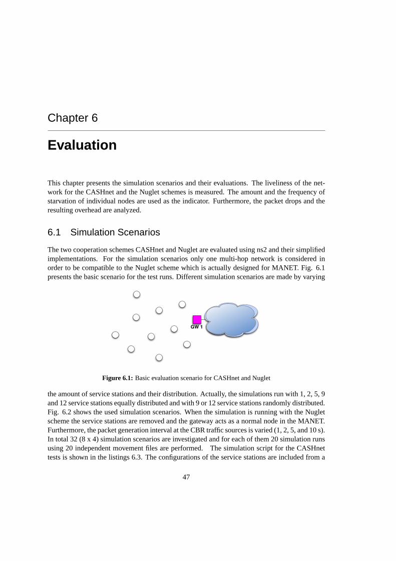
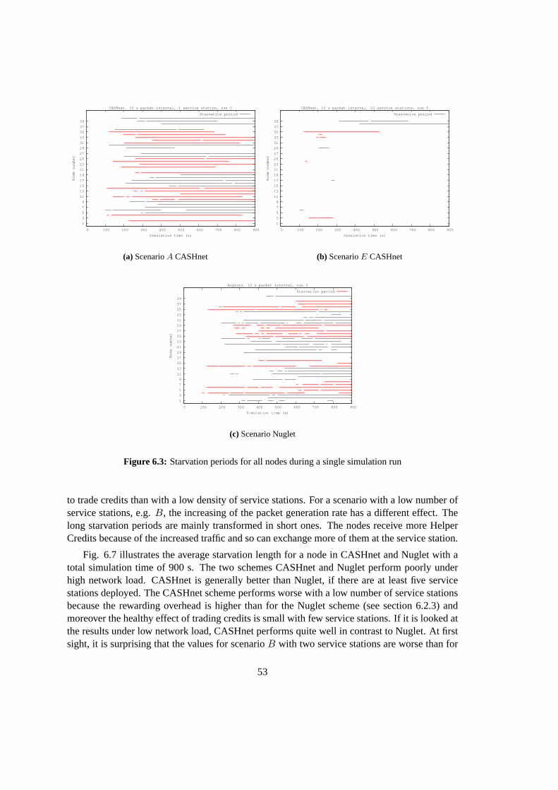
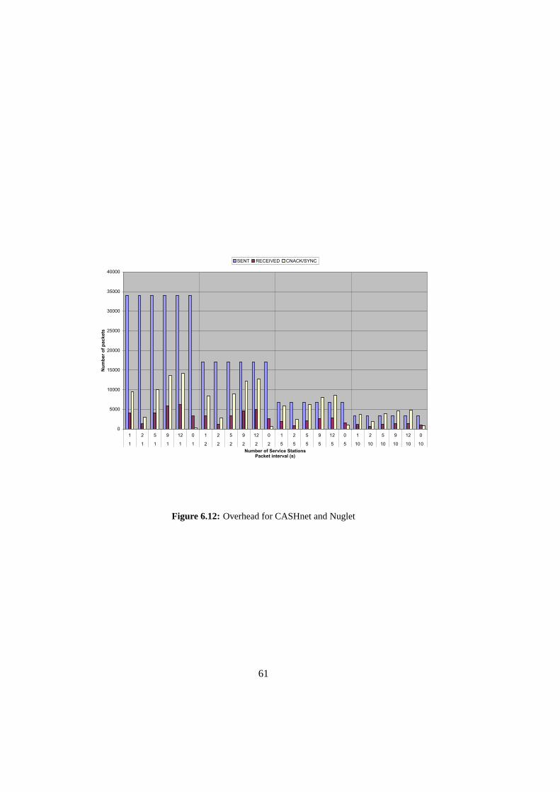
6.1 Basic evaluation scenario for CASHnet and Nuglet . . . . . . . . . . . . . . . 476.2 Simulation scenarios with distribution of the service stations . . . . . . . . . . 496.3 Starvation periods for all nodes during a single simulation run . . . . . . . . . 53
5.1 Four Example lines of a trace file with the new wireless trace file format . . . . 385.2 OTcl Interface Extensions for CASHnet . . . . . . . . . . . . . . . . . . . . . 455.3 OTcl Interface Extensions for Nuglet . . . . . . . . . . . . . . . . . . . . . . 466.1 Example service station file . . . . . . . . . . . . . . . . . . . . . . . . . . . . 486.2 Example lines of a node movement file . . . . . . . . . . . . . . . . . . . . . . 486.3 Simulation script for CASHnet . . . . . . . . . . . . . . . . . . . . . . . . . . 49
ix
Acknowledgment
First of all, I would like to dedicate some words to the people who contributed to the success ofmy thesis.I owe many thanks to Professor Dr. Torsten Braun for supervising my thesis. Furthermore,I would like to express my gratitude to Attila Weyland. He supported me during the wholediploma work, gave me many valuable hints and recommendations, and sacrificed a lot of hisspare-time in order to proof-read my thesis several times. Many thanks go to Dr. Florian Baum-gartner and Matthias Scheidegger for providing technical support. Moreover, I want to thankNiklaus Steiner and Vivian Kilchherr for proof-reading this thesis. Finally, I would like to thankmy family and my girlfriend for their support.
xi
Chapter 1
Introduction
Todays wireless networks consist of a number of access points deployed by a provider in limitedareas where a certain amount of customers are expected, e.g. at railway stations or at airports.Potential customers outside the area covered by the provider’s access points can not participate inthe network. Only the customers in the restricted area of the access points can provide revenuefor the provider. The only solution is to deploy more access points which can be limited bylocation properties in addition to financial issues.
A promising concept to cover bigger areas with wireless networks is a multi-hop cellularnetwork. In this network the single hop limit to the access point is removed. The customers actas packet forwarders and a gateway offers the Internet connectivity. The size of the covered areaincreases without deploying new access points. The advantages of a mobile ad-hoc networkare combined with the existing network infrastructure. But this concept includes also somedrawbacks of a mobile ad-hoc network. Routing information has to be maintained accurate, thecustomers have to be protected from attacks that are possible because of the open architecture,as well as the cooperation among the customers has to be ensured.
The willingness to cooperate in such a network becomes a challenge. The customers tendto give priority to their self-generated packets over packets of other customers, although theycan have a common interest in Internet connectivity. This problem becomes more critical whenenergy is regarded as a precious and limited good. No-one would forward packets for the benefitof others if as consequence he has no energy left for the transmission of his own packets. Thisnatural selfishness of the customers prevents such a network to be kept alive.
The CASHnet [16, 17, 18] cooperation scheme addresses the shown issues in a decentralizedmanner. It accepts that the individual customer plays an important role in such a network andhis participation must be encouraged. It stimulates the cooperation by making it a rewardingalternative to the selfishness. The customers have to pay for their self-generated packets with acertain amount of Traffic Credits. The customers that forward packets for the benefit of othersare rewarded and can save money by not having to buy Traffic Credits.
For this thesis an implementation of the promising CASHnet scheme is made in a networksimulator to verify its feasibility. Furthermore, another cooperation scheme called Nuglet [19]is implemented to make a comparison with the CASHnet scheme.
This thesis is structured as follows. The chapter 2 provides an overview of the differenttypes of wireless networks. In the chapter 3 the different routing concepts in a mobile ad-hoc
1
network are illustrated and a closer look is taken to the used routing protocol AODV (Ad-hocOn-Demand Distance Vector) and an enhancement of it. In the chapter 4 the cooperation inmobile ad-hoc networks, different cooperation concepts, the CASHnet and the Nuglet schemeare discussed. The implementations of CASHnet and Nuglet in the network simulator are treatedin chapter 5. The chapter 6 shows the simulation scenarios and their evaluations. Finally, thechapter 7 presents the made conclusions and an outlook to future work.
2
Chapter 2
Wireless Networks
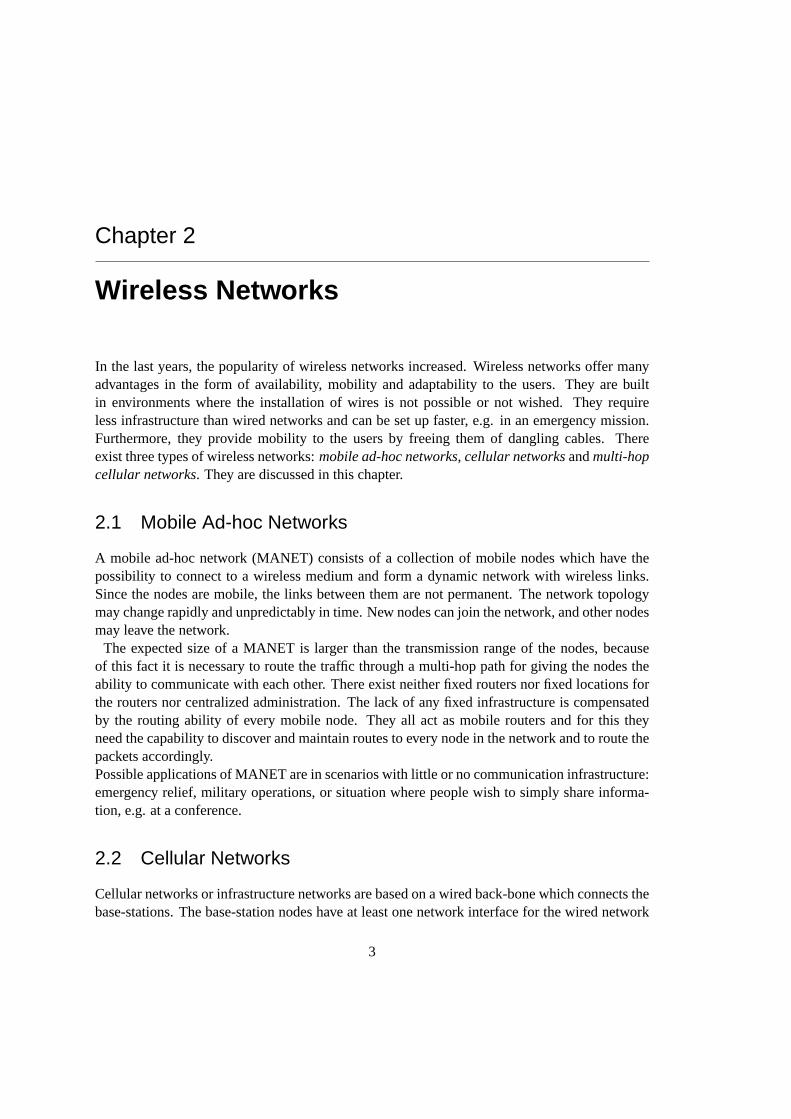
In the last years, the popularity of wireless networks increased. Wireless networks offer manyadvantages in the form of availability, mobility and adaptability to the users. They are builtin environments where the installation of wires is not possible or not wished. They requireless infrastructure than wired networks and can be set up faster, e.g. in an emergency mission.Furthermore, they provide mobility to the users by freeing them of dangling cables. Thereexist three types of wireless networks:mobile ad-hoc networks, cellular networksandmulti-hopcellular networks. They are discussed in this chapter.
2.1 Mobile Ad-hoc Networks
A mobile ad-hoc network (MANET) consists of a collection of mobile nodes which have thepossibility to connect to a wireless medium and form a dynamic network with wireless links.Since the nodes are mobile, the links between them are not permanent. The network topologymay change rapidly and unpredictably in time. New nodes can join the network, and other nodesmay leave the network.
The expected size of a MANET is larger than the transmission range of the nodes, becauseof this fact it is necessary to route the traffic through a multi-hop path for giving the nodes theability to communicate with each other. There exist neither fixed routers nor fixed locations forthe routers nor centralized administration. The lack of any fixed infrastructure is compensatedby the routing ability of every mobile node. They all act as mobile routers and for this theyneed the capability to discover and maintain routes to every node in the network and to route thepackets accordingly.Possible applications of MANET are in scenarios with little or no communication infrastructure:emergency relief, military operations, or situation where people wish to simply share informa-tion, e.g. at a conference.
2.2 Cellular Networks
Cellular networks or infrastructure networks are based on a wired back-bone which connects thebase-stations. The base-station nodes have at least one network interface for the wired network
3
Figure 2.1: Mobile ad-hoc network
and one or more wireless network interfaces to provide communication to the mobile nodes. Thecommunication of the mobile node is only possible over a one-hop link to base-station. Directlinks between nodes or multi-hop links to the base-station are not possible.The size of a cellular network is limited by the transmission range of the base-stations. If the
movement with hand-over
Figure 2.2: Cellular network
node is out of the transmission range of the base-stations, no communication is possible. Insidethe area covered by the base-stations it may move without losing connection and if it leaves thetransmission range of the current base-station, a hand-over to a another base-station will let thenode communicate seamlessly.
4
2.3 Multi-hop Cellular Networks
In multi-hop cellular networks the two concepts described before are combined. On the one handthere is a cellular network, on the other hand there are mobile nodes with additional routingfacilities. With this approach it is possible to have multiple hops between a mobile node anda base-station. The idea is to benefit from existing infrastructure and to gain more efficiencyout of it, to cover wider areas with less fixed antennas and base-stations and to reduce powerconsumption due to shorter hop distances. In [2] some benefits of enhancing cellular networkwith ad-hoc technologies are shown.
Figure 2.3: Multi-hop cellular network
5
Chapter 3
Routing in Mobile Ad-hoc Networks
In this chapter different concepts of routing in MANET are shown. Further the mobile ad-hoc routing protocol AODV (Ad-hoc On-Demand Distance Vector) is discussed in more detailbecause it is used in the implementation of CASHnet and Nuglet.
3.1 Concepts
A routing protocol for a mobile ad-hoc environment is in urgent need of the following capabili-ties:
• Loop-freeness
• Multi-hop paths
• Self-starting
• Dynamic maintenance of the network topology
• Fast convergence
• Minimal Routing overhead
• Economical consumption of resources, e.g. memory and bandwidth
• Minimized and kept local effect of link breakage
• Scalability with large numbers of nodes
Different concepts for mobile ad-hoc routing are established in order to reach these capabilities.There are different interdependences between the wished capabilities. Because of this, thereexists no concept that is optimal in all aspects. Each approach has to make a compromise on thedifferent capabilities.
7
3.1.1 Position Based Protocols
This concept makes use of location information [3]. The routing can be based on the locationinformation either to flood route requests or to forward the data packets. The basic componentsof a position based routing are:
• positioning service to determine the physical position of the node, e.g. GPS
• location service to determine the position of the destination, e.g. DREAM [4], Quorumbased
• forwarding strategy, i.e. selection of the next node
3.1.2 Topology Based or Non-Position Based Protocols
The topology based protocols do not make use of additional location information. They utilizenetwork topology information to make a routing decision.
Proactive Protocols
In proactive or table-driven protocols, the nodes in the network maintain a table of routes toevery destination. They periodically exchange messages to keep the routing table up-to-date.At all times the routes to all destinations are ready to use which keeps the delays to send datapackets. The maintenance of routes to all destinations, even if they are not used, consumes alot of bandwidth and network resources. It can even end in increasing delays because of queuesfilled up with control packets and more packet collisions due to more network traffic. As a resultproactive protocols do not scale in the frequency of topology change. Therefore they are onlyappropriate for low mobility networks.
Representatives of proactive protocols are DSDV (Destination-Sequenced Distance VectorRouting) [6] and OLSR (Optimized Link State Routing) [7, 8].DSDV is a distance vector protocol which uses the Bellmann-Ford algorithm. A sequence num-ber is added to guarantee loop-freedom by distinguishing stale routes from new ones.OLSR is a proactive link state routing protocol. Its neighbor sensing is based on periodic ex-change ofHELLO messages. It reduces the flooding of control traffic by using the concept ofmulti-point relays and computes the routes with the shortest-path algorithm.
Reactive Protocols
Reactive (or on-demand) protocols acquire only routing information upon request. They aredesigned to overcome the wasted effort in maintaining unused routes. Routes are searched on-demand. When a node requires a new route to a destination, it starts a route discovery process.This process ends once that a valid route is found or all possible routes are checked. The nodesare not forced to maintain unused routes, but on the other hand the latency for sending datapackets will considerably increase. A long delay before data transmission can arise because thetransmission has to wait until a valid route to the destination is acquired. As reactive routing
8
protocols flood the network to discover the wished route, they are not optimal in terms of band-width utilization, but scale well in highly dynamic networks. Thus this strategy is suitable forhigh mobility networks.
Exponents of this strategy are e.g. TORA (Temporally-Ordered Routing Algorithm) [9],DSR (Dynamic Source Routing) [10] and AODV (Ad-Hoc On-Demand Distance Vector Rout-ing) [11, 12].TORA is built on the concept of link reversal. The main design concept is to reduce the controlmessages to few nodes near the topology change by using a destination based acyclic graph.DSR is based on source routing. A sender has to get the complete sequence of nodes to thedestination and includes this list of intermediate nodes in the packet header before sending thepacket. A closer look to AODV is taken in the following section.
3.2 Examples
3.2.1 AODV
AODV [11, 12] is a reactive mobile ad-hoc routing protocol. It joins the mechanisms of DSDVand DSR. The periodic beacons, hop-by-hop routing and the sequence numbers of DSDV and thepure on-demand mechanism ofRoute DiscoveryandRoute Maintenanceof DSR are combined.
As an important feature AODV uses a destination sequence number for each route entry. Thisdestination sequence number is generated by the destination node and is sent to the requestingnode. This trivially insures loop-freedom by simply selecting the route with the highest sequencenumber as the actual one.
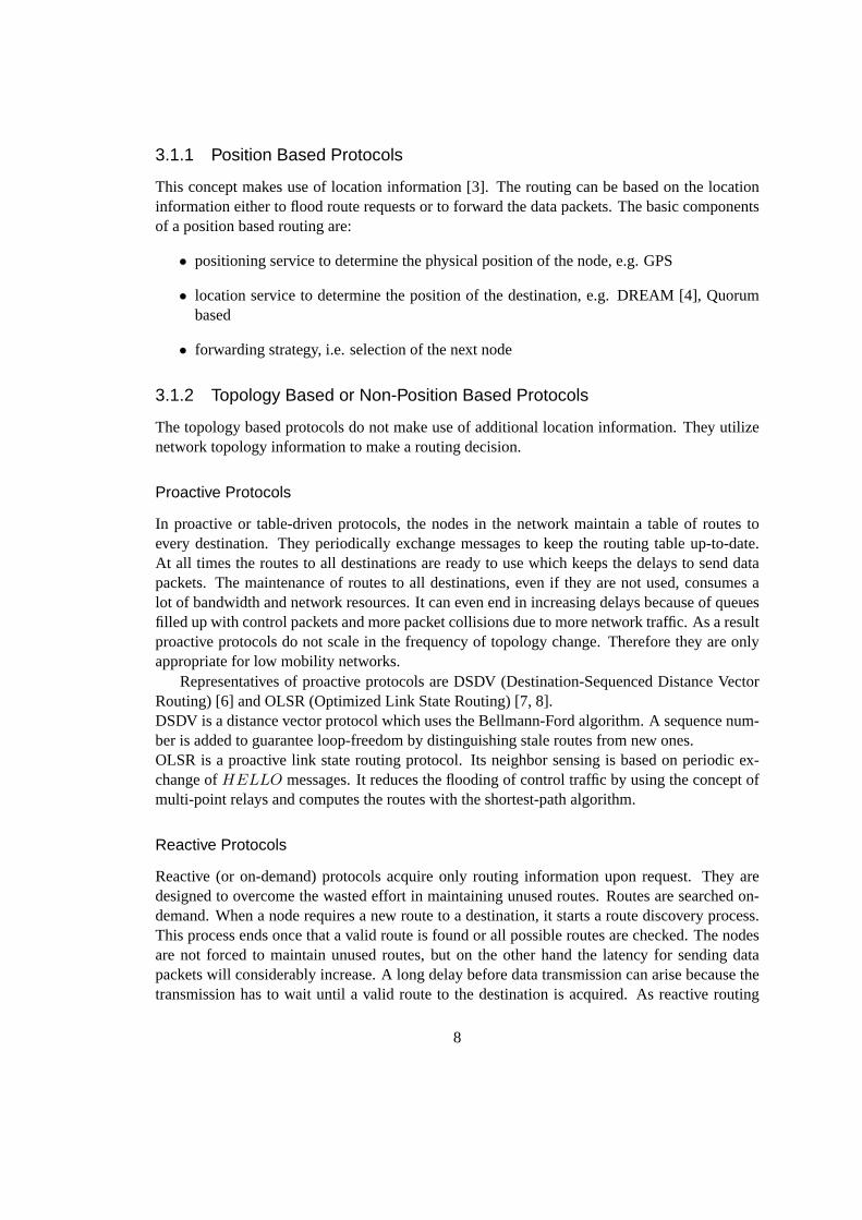
AODV has four types of messages: Route Requests (RREQ), Route Replies (RREP ), RouteErrors (RERR), and Route Replies Acknowledgment (RREP − ACK). The different mes-sages are shown in Fig. 3.1 - 3.4. All these messages are received via UDP using normal IPheader processing. AODV uses the IP limited broadcast address (255.255.255.255) to broadcastmessages.
Type 1 for RREQ2 for RREP3 for RERR4 for RREP − ACK
J Join Flag; reserved for multicast.R Repair Flag; reserved for multicast.G Gratuitous RREP flag; indicates
whether a gratuitousRREP should beunicast to the destination node.
D Destination only flag; only the destina-tion node may answer to thisRREQ,no intermediate node is allowed of an-swering with aRREP .
U Unknown sequence number.A Acknowledgment required; used, if
there is a danger of unidirectional links.It causes the receiver of theRREPmessage to send back aRREP −ACK message. The reception ofsuch an acknowledgment provides as-surance that the link is currently bidi-rectional.
N No delete flag; set if upstream nodesshould not delete the route, although anode has performed a local repair of alink.
10
Sequence Number and Routing Table Management
It is crucial for AODV to properly handle the sequence numbers. A node has to update its ownsequence number in two cases:
• Before starting a route discovery process, the node has to increment its own sequencenumber.
• A destination node has to update its own sequence number to the maximum of its currentsequence number and the destination sequence number inRREQ packet immediatelybefore transmitting theRREP packet.
The sequence numbers in the routing table entries may be changed by the node only in thefollowing circumstances:
• Offer of a new route to itself, if it is the destination node.
• Reception of an AODV message with new information about the sequence number for adestination.
• Expiration of path or path breaks.
When a node receives an AODV control message, either to create or to update a route for aparticular destination, it searches its routing table for an entry to the destination. If there is noroute entry, it creates a new one with the sequence number contained in the control packet, orelse the sequence number is set invalid. Otherwise, the node compares the existing entry withthe new information and updates it if either
• the new sequence number is higher than in the routing table entry,
• the sequence numbers are equal and the new hop count plus one is smaller than in theexisting route, or
• the sequence number is unknown.
Besides the destination sequence numbers, the routing entry for each valid route contains aprecursor list. This list contains all precursor of the node which are able to forward packets onthis route. All neighboring nodes to which aRREP was generated or forwarded are includedin this list. In the event of a next hop link breakage, notifications are sent to those nodes.The routing table entries of AODV consist of the following entries:
• Destination IP Address
• Destination Sequence Number
• Valid Destination Sequence Number flag
• Routing and state flags
• Network Interface
11
• Hop Count (distance in hops to reach the destination)
• Next Hop
• List of Precursors (as mentioned above)
• Lifetime (deletion time of the route entry)
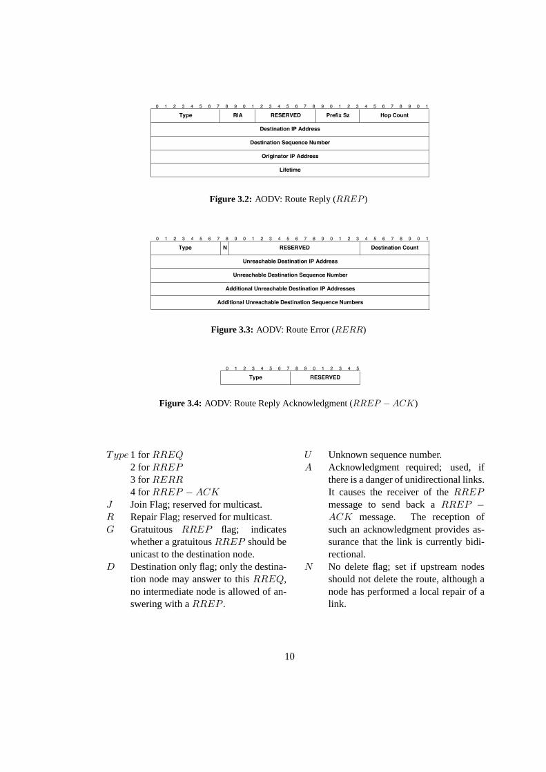
Route Discovery
If a valid route exists between two communication peers, AODV takes no action. When a newroute is needed, theRoute Discoverymechanism is started. The source node has to send aRREQ message. The sequence number field in theRREQ is set to the last known destina-tion sequence number or if not available the unknown sequence number field is set. The ownsequence number is incremented and included in the Originator Sequence Number field of themessage. TheRREQ ID field is incremented by one of the node’s currentRREQ ID. The hopcount is set to zero. The node buffers theRREQ ID and the Originator IP address ofRREQbefore broadcasting it. The source node waits now for aRREP message. If it does not retrieveone within a certain time, it may broadcast anotherRREQ. If the maximum number of retrieshas been reached, all data packets for this destination are dropped and a destination unreachablemessage is delivered to their originators.
SourceDestination
RREQ
RREQRREQ
RREQ RREQRREQRREQ
RREQ
RREQ
RREQ RREQRREQ
(a) Route Request (RREQ)
SourceDestinationRREP
RREPRREP
RREPRREP
(b) Route Reply (RREP )
Figure 3.5: AODV: Route Discovery
The intermediate node which is receiving theRREQ checks if it has already received a messagewith the same Originator Address andRREQ ID within a certain time. If aRREQ has beenalready received, the newly received message is discarded. Otherwise, the node increments thehop count in theRREQ and searches for a reverse route to the originator and creates or updatesits route entry in the routing table. The destination sequence number of the reverse route in therouting table is set to the Originator Sequence Number if it is greater, the sequence number is setvalid, the hop count is copied from theRREQ and the next hop is changed. If the intermediatenode has a fresh enough valid route to the destination, it unicasts aRREP , whose hop count isset to the hop distance of the current node to the destination, to the source node and discards theRREQ. Otherwise, it broadcasts theRREQ.
When theRREQ reaches the destination node, the node sends aRREP back towards thesource of theRREQ using the reverse route. The destination node increments its own sequence
12
number and puts it in the Destination Sequence Number field. The hop count is reset to zero.Each intermediate node forwarding theRREP always increments the hop count. As soon asthe source node retrieves theRREP , it is able to transmit the data packets to the destination.
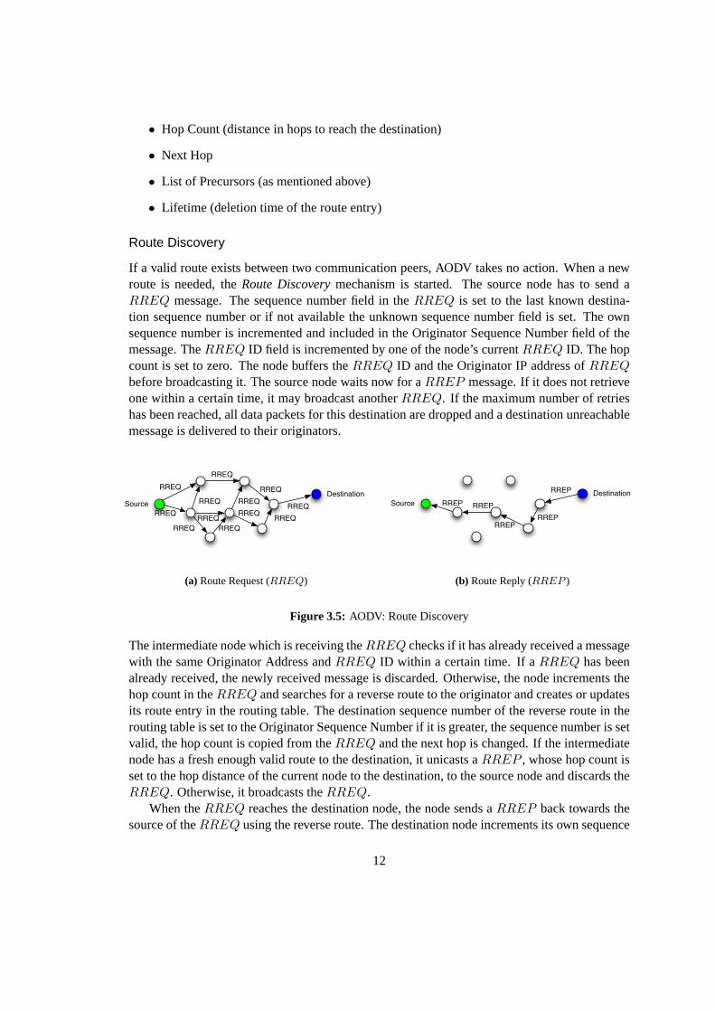
Route Maintenance
Nodes which are part of an active route can deliver connectivity information by broadcastingHELLO messages. AHELLO message is aRREP message with TTL = 1. By listeningfor packets from its neighbor nodes a node can determine the connectivity. If it receives neitherHELLO nor other messages from a certain node during a certain interval, it has to assume alink break. Local connectivity can also be surveyed by using link layer notification. The node
SourceDestination
active route
X
node movement
RERRRERR
(a) Route Error (RERR)
HELLO
HELLOHELLO
HELLO
(b) PeriodicHELLO messages
Figure 3.6: AODV: Route Maintenance
sends aRERR to all nodes in the precursor list of the concerned route, if it has detected a linkbreak for the next hop of an active route, or if it gets data packets for a node for which it doesnot have an active route, or if it receives aRERR from a neighbor for an active route.
3.2.2 AODV+
AODV+ [13] is an implementation of global connectivity for mobile ad hoc networks as pre-sented in [14]. It is currently being implemented for the network simulator ns2 [15]. The usedconcepts are kept general and could be adapted to a real implementation.
The work is focused on interworking between a mobile ad-hoc network and the Internet.Gateways are needed to send packets outside the mobile ad-hoc network. These gateways areable to route messages in both networks. Therefore they support mobile ad-hoc routing androuting in the wired domain. [14] explains the operation of the mobile nodes and the gateways.The application of these concepts for a reactive routing protocol heads in adaptation of the routediscovery messages (RREP , RREQ), so that it is possible to detect gateways. TheRREQ isextended by an additional flag which is calledInternet-Global Address Resolution Flagor I-flag(RREQI ). A setI-flag indicates that the source node requests global connectivity and wants torecover a gateway. TheRREP is also extended by the same additionalI-flag. The new flag intheRREPI message indicates that the message contains information about a gateway.
13
In order to get access to the wired network, the node needs to learn the location and the addressof a gateway. The route to the gateways is then used as default route to send packet outside theMANET. There are different ways to catch information about the gateways:
• the gateway broadcasts periodically messages (proactive gateway discovery)
• the mobile node requests a default route to a gateway by sending aRREQI message(reactive gateway discovery)
• the gateways replies on receivedRREQ with aRREPI
The mobile node adds this information about the gateway to its routing table as thedefault routeentry. If the mobile node has no route to a certain node, it broadcasts aRREQ. If it does notreceive aRREP , the node is supposed to be outside the current mobile ad-hoc network. Thepacket is sent to this node by using thedefault routeto the gateway.
Proactive Gateway Discovery
The gateway discovery is initiated by the gateways themselves. They broadcast periodically agateway advertisement(GWADV ) message to the whole mobile ad-hoc network. It is impor-tant to carefully choose the broadcasting interval to not flood the network unnecessarily.
GW
GWADV
GWADVGWADV
GWADV
Figure 3.7: AODV+: Proactive Gateway Discovery
The mobile nodes receiving thisGWADV message complete their routing tables with the de-fault route to the gateway. Although the problem of duplicated broadcast messages is solvedwith the same mechanism as in AODV (RREQ ID), the periodical flooding of the whole net-work remains a big disadvantage of this approach. The cost of the flooding can not be ignoredbecause of the limited resources in a mobile ad-hoc network.
Reactive Gateway Discovery
The mobile node that needs a route to a gateway broadcasts aRREQI . Only gateways react onthis message by unicasting aRREPI back to the mobile node. Intermediate nodes only forwardtheRREQI . They prevent the duplicated forwarding with the knownRREQ ID mechanism.The advantage of this approach is that it is purely reactive. Only if routes to the gateway are
14
GW
RREQ_I
RREQ_I
RREQ_IRREQ_I
RREQ_I
RREQ_I
RREQ_I
RREQ_I
RREQ_I
RREQ_IRREQ_I
RREQ_I
RREQ_I
RREQ_I
RREQ_I
(a) Source node broadcasts aRREQI
GW
RREP_IRREP_I
RREP_I
(b) Gateway unicasts aRREPI
Figure 3.8: AODV+: Reactive Gateway Discovery
needed, a request is started. Disadvantages are that the load on the forwarding node near thegateway is increased and the response time is higher.
Hybrid Gateway Discovery
The two approaches are combined. The gateway broadcasts periodicallyRREPI messageswhich are forwarded within the advertisement zone. Proactive gateway discovery is used for thisarea. The nodes outside of it have to start a reactive gateway discovery by sending aRREQI
message.
GW
advertisement zone
GWADV
GWADVGWADV
GWADV
GWADV
GWADV
GWADV
reactive zone
Figure 3.9: AODV+: Hybrid Gateway Discovery
15
Chapter 4
Cooperation in Mobile Ad-hoc Networks
In this chapter the need of cooperation in a MANET and various concepts of stimulating thiscooperation are discussed. Furthermore, a closer look to the cooperation schemes CASHnet[16, 17, 18] and Nuglet [19] is taken.
4.1 Introduction
The field of application of MANET has become broader. Besides the use in emergency ormilitary scenarios where all nodes belong to one authority, civilian and commercial scenariosare becoming more and more important today. Each node in the new scenarios forms its ownauthority. The nodes do not simply cooperate with each other by forwarding the packets. Theyact for their own profit. The individuality of the nodes causes selfishness. The selfishness of thenodes is expressed in the refusal of cooperation. For example, a node does not forward packetsfrom other nodes in order to save its limited energy. It has no interest in spending its limitedresources for the other nodes. It rather saves its resources to be able to send own packets. Thisbehavior of the nodes leads to a malfunctioning MANET. It is no more possible to send packetsover multiple hops. Therefore, the nodes have to be encouraged or forced to cooperate, in orderto keep the MANET alive.
4.2 Concepts
There are different concepts to stimulate cooperation in a MANET or a multi-hop cellular net-work. The following two main concepts are distinguished, but certain cooperation schemes areusing a mix of them.
4.2.1 Monitor and Punish Misbehavior
The activities of a node are monitored by a central authority or by the neighboring nodes. If aselfish behavior is detected, e.g. the node does not forward packets for the benefit of others, thenode is punished. The node may be excluded from the network. It cannot send self-generated
17
packets to the network. Other actions are taken such as routing the packets around the non-cooperative node.
In the CONFIDANT [20] scheme cooperation is forced by detecting and isolating misbe-having nodes. Trust relationships and routing decisions are based on experienced, observed, orreported routing and forwarding behavior of the other nodes. A reputation system is included ineach node. It maintains a local rating list. The monitoring is done byneighborhood watch, i.e.a node is observed by its one-hop neighbors. If a malicious or selfish nodeM is detected, thedetecting node sends anALARMM message to all itsfriends, i.e. trusted nodes, and adjusts therating ofM . A reception of anALARMM message invokes also the reputation system of thenode and causes an adaptation of the reputation level of the malicious nodeM . The paths forthe packets are chosen regarding the nodes’ ratings. Further, no route requests from maliciousnodes are processed. This leads to an isolation of the malicious nodes from the network untiltheir ratings are better. The problem is that a collective false accusation can exclude a nodefrom the network without a fault of itself. The security is based on trust relationships and thereputation system.
In [21] the monitoring concept is combined with credits. The packet originator attaches apayment token to the packet. There is one payment per packet and not as in other schemes onepayment per payee. The payment token can be thought of as alottery ticket. Each intermediatenode on the path verifies if the payment token is a winning ticket for it. The winning ticketsare reported to the next base-station. This report includes also the identities of the neighboringnodes on the packet’s path. The neighbor rewards encourage the node to forward the packeteven if it does not receive a winning ticket. After the base-station has verified the validity of thepayment token, it sends the packet to its destination over the backbone network. The accountingcenter compares the winning tickets reports and the payment tokens received from the base-station. It credits the claimant and its reported neighbors. Furthermore, it charges a usage fee tothe packet originator’s account. Moreover, the central authority audits the behavior of the nodesby analyzing the collected information received from the base-station.
4.2.2 Rewarding Cooperation
This concept gives the cooperative node a reward for its forwarding of the packets for the benefitof other nodes. The concept is closely connected to a credit (virtual currency) or micro paymentsystem. The originator and/or the receiver of a packet have to pay for the packet transmission.
Rewards have been introduced in the Sprite [22] scheme as incentive for cooperation in aMANET. The nodes are connected to theCredit Clearance Service(CCS) via a wireless overlaynetwork, e.g. GPSR. The security concept is based on aPublic Key Infrastructure(PKI). Acertificate identifies the individual nodes and the messages are digitally signed. Furthermore,the sender knows the full path to the destination from a secure ad-hoc routing protocol basedon DSR. The full path is included in the message. The receiving nodes verify the signature andif they are on the path. If any condition is not satisfied, the packet is dropped. Otherwise, thenode processes the packet and saves the receipt. The node reports its receiving and forwardingactivities by sending these receipts to the CCS. According to the receipts the CCS determines thecharge and credit to each node that participated in the transmission of a packet. The originator
18
of the packet has to pay for the transmission. The intermediate nodes are rewarded. The authorsof [22] validated the system using a game-theoretic perspective.
The authors of [23] and [24] propose charging schemes for a multi-hop cellular networkenvironment. Both schemes are based on centralized accounting and security mechanisms. Theyrequire complete routing information from the sender to the receiver, i.e. source routing. Butsource routing does not scale well under high node mobility. Furthermore, the schemes do notsupport cost sharing between sender and receiver.
[23] requires an existingAuthentication, Authorization and Accounting(AAA) infrastruc-ture. The node authenticates itself in the provider’s network by using the AAA infrastructure.The authenticated node uses an on-demand source routing protocol to get the full path to the de-sired destination. It sends the packet equipped with its certificate, the digitally signed full routingpath and the keyed hash value on itself and the destination. The intermediate node checks thesignature and the certificate. If it is correct, the node computes the new value for the hash chainand forwards the packet. The last intermediate node acquires a digitally signed confirmation ofthe received amount of data from the destination. After that, it notifies the access point (AP)about this confirmation and the intermediate nodes involved in the transmission. The AP veri-fies the participation of the each node and the data amount. It charges a volume-based fee to thesender’s account and credits the intermediate nodes for their forwarding behavior.
In order to participate in the network, a node in [24] has to register itself at the provider. Itreceives a long-term symmetric key. The sender nodeS has to establish an end-to-end sessionto the destinationD. This is done by generating aninitiator sessionbetweenS and its base-stationBSS and acorrespondent sessionbetweenD and its base-stationBSD. Therefore, allcommunication passes through a base-station. The remuneration is done by charging the initiatorS of the communication and rewarding the forwarding nodes.S pays for the traffic in bothdirections. The trusted provider of the base-stations maintains a billing account for every node inthe multi-hop cellular network. The initiator is charged when the packet has passed through thebase-station. The up-stream forwarding nodes are rewarded when the base-station has receivedan acknowledgment message that confirms the reception of the packet at the destinationD. Inorder to motivateD to acknowledge the packet reception, the destination is charged a small feeεwhen the packet is sent to the destination’s network.ε is reimbursed when the acknowledgmentis received at the base-station.
In the Nuglet [19] scheme cooperation in a MANET is enforced. A node can only send aself-generated packet, if it has earned enough credits by forwarding packets of other nodes. Incontrast, the CASHnet [16, 17, 18] scheme lets the decision of participation in the multi-hopcellular network at the node’s side, i.e. a node can even send self-generated packets, if he is notforwarding packets for others. But the node can earn credits by participation in the network, itcan lower its costs for sending packets. The CASHnet and the Nuglet cooperation scheme arediscussed in more details in the section 4.3.
Comparison
The tables 4.1 and 4.2 present a quick overview of the shown cooperation schemes. In table 4.1the schemes are categorized according their architecture, security concept and their stimulationtype. A decentral cooperation architecture is more suitable for a MANET because of its decentral
19
nature. Furthermore, a decentral cooperation architecture can also be preferable for a multi-hopcellular network. But it makes the security concept more complex. The security concept iseither based on trust and reputation, symmetric session keys, PKI or AAA architecture. Thischoice has influences of the power used at the mobile node, e.g. the use of public / private keycryptography consumes a lot of processing power and therefore energy at the node.
Table 4.2 classifies the cooperation schemes according further criteria. The monitoringschemes observe the cooperation behavior of the nodes in contrast to the shown rewardingschemes. The schemes are initially targeted for a specific network type (MANET or a multi-hop cellular network). They have certain requirements concerning the routing protocol. TheCASHnet and the Nuglet scheme requires only hop count information from the routing protocolin contrast to the other schemes that require source routing. They provide more flexibility in thechoice of the routing protocol.
scheme architecture security concept stimulation type
Nuglet [19] decentral PKIsecurity associationsmessage signing with sym-metric session key
enforcement of cooperation(rewarding)
CASHnet [18] decentral with servicepoints
PKImessage signing using pub-lic key
rewarding
CONFIDANT [20] decentral decentraltrust relationships + reputa-tion system
monitor / punishment ofmisbehavior
Sprite [22] central authorityoverlay network
PKImessage signing
rewarding(node reports forwardingactivities to central author-ity)
[21] central symmetric session keys monitoring(rewards / punishments)
[23] centralauthentication /accounting
AAA architecturesymmetric session keyshash chain
rewarding
[24] centralaccounting
symmetric session keysall traffic is routed overbase-station
rewarding
Table 4.1: Comparison of cooperation schemes I
4.3 Examples
4.3.1 CASHnet
The CASHnet [16, 17, 18] is targeted at multi-hop cellular network as shown in Fig. 4.1. Theinfrastructure, such as the gateways and the service stations, is offered by a provider. The CASH-net scheme provides decentralized accounting and security mechanisms in this multi-hop cellular
20
scheme monitoring routing information target network
Nuglet [19] no hop count MANETCASHnet [18] no hop count multi-hop cellular networkCONFIDANT [20] yes
neighbors monitor thenode
full pathreactive source routingDSR
MANET
Sprite [22] no full pathsource routingDSR
MANET
[21] yes.central authority
source routingDSR
multi-hop cellular network
[23] no source routing multi-hop cellular network[24] no source routing multi-hop cellular network
Table 4.2: Comparison of cooperation schemes II
GW 1 GW 2
sender's network receiver's networkwired network
sender
receiver
Figure 4.1: CASHnet: Example scenario
21
network. It supports sender- and receiver-based payments, and does not require complete routeinformation from the sender to the receiver. It coexists with pure ad-hoc traffic. The nodes areneither charged nor remunerated for this ad-hoc only traffic. Because pure ad-hoc communica-tion does not cause any costs in terms of bandwidth for the provider, it should be free of charge.By providing monetary rewards to cooperative nodes, cooperation becomes a gainful alternativeto selfishness for the nodes. It is a rewarding scheme.
The security mechanisms are implemented in a tamper resistant device, e.g. a smart card.They rely on aPublic Key Infrastructure(PKI) system. This security service could be chargedas a subscription fee in order to receive the smart card. Besides the gateways, the provider alsooffers service stations where the users can trade earned Helper Credits and buy further TrafficCredits. The service stations could be integrated in the gateways as well as additionally installedwithin the ad-hoc network.CASHnet requires the following components:
• A tamper resistant device, e.g. a smart card, that provides a protected environment toexecute safely the CASHnet functions. It contains the counters for Traffic Credits andHelper Credits, the node’s public / private key pair and the node’s certificate, the provider’spublic key and two internal lists (Reward and Authentication List). Each node needs sucha tamper resistant device. It is sold by the provider as todays SIM cards for GSM mobiletelephony.
• A routing algorithm that provides hop count information (e.g. AODV or DSR).
• Gateways that route the messages between the MANET and the wired backbone of theprovider.
• service stations of the provider. There, the nodes can buy Traffic Credits, trade HelperCredits, or renew their certificate. The service stations can be imagined as todays ATM.
The security architecture of CASHnet is based on public key cryptography. The provider issuescertificates to the nodes. The nodes authenticate themselves with these certificates. The certifi-cates have a short lifetime to avoid the creation of bogus nodes. This fact forces the nodes toregularly visit one of the provider’s service station to renew it. All data messages are digitallysigned to guarantee non-repudiation, which provides data integrity and data origin authentica-tion.
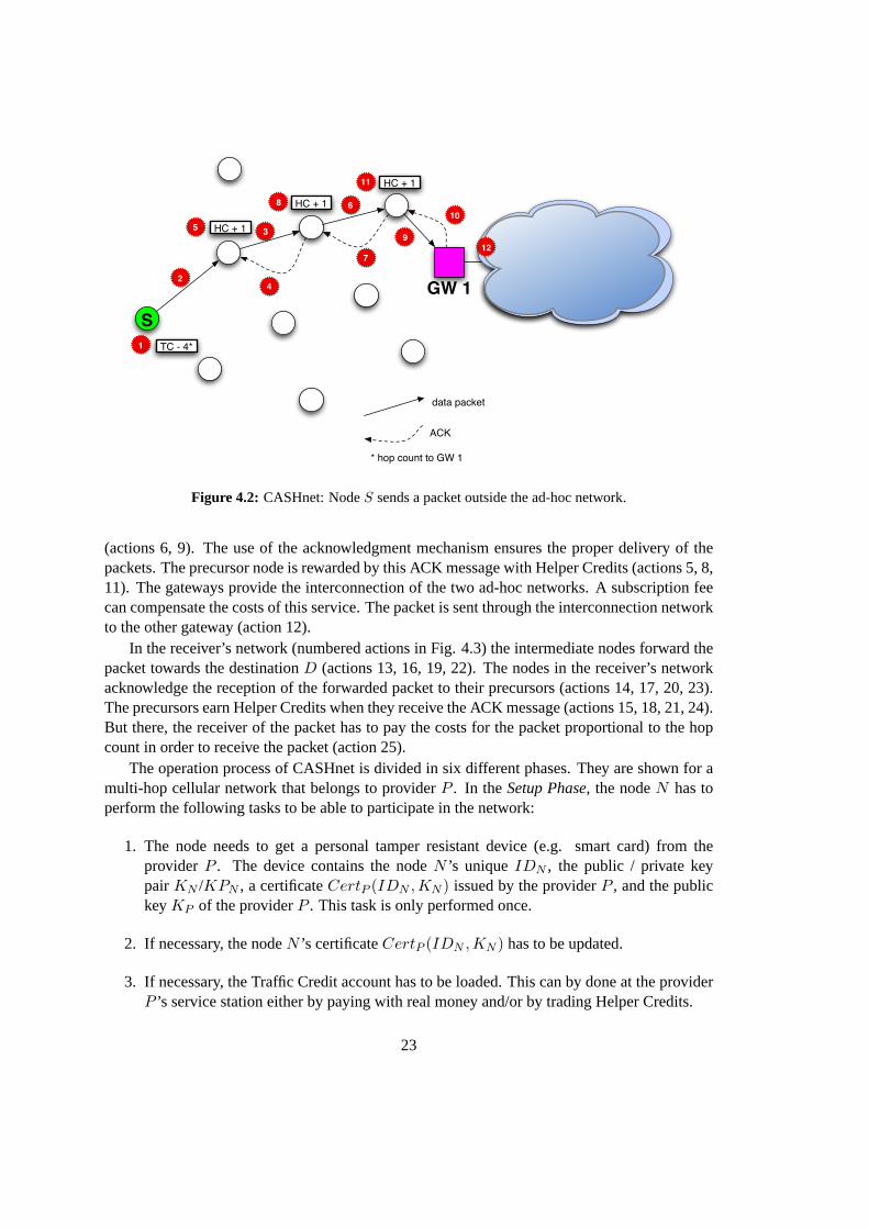
The charging and rewarding mechanism of CASHnet in the sender network is shown innumbered actions in Fig. 4.2. If nodeS wants to send a self-generated packet outside the ad-hoc network, it has to pay with Traffic Credits. The costs are proportional to the hop count tothe gateway. Every intermediate node that forwards the packet gets Helper Credits. As alreadymentioned, Traffic Credits can be bought for real money or traded for Helper Credits at a servicestation. After paying for the packet transmission (action 1), the packet can be sent to the nextnode (action 2). The first intermediate node forwards the packet without sending an acknow-ledgment message (ACK) because the originator of the packet should not be rewarded (action3). The following nodes confirm the reception of the packet by sending an acknowledgmentmessage (ACK) to the precursor node (actions 4, 7, 10) and forward the packet to the next hop
22
data packet
ACK
SGW 1
1
6
5
4
3
2
7
8
9
10
11
HC + 1
TC - 4*
* hop count to GW 1
12
HC + 1
HC + 1
Figure 4.2: CASHnet: NodeS sends a packet outside the ad-hoc network.
(actions 6, 9). The use of the acknowledgment mechanism ensures the proper delivery of thepackets. The precursor node is rewarded by this ACK message with Helper Credits (actions 5, 8,11). The gateways provide the interconnection of the two ad-hoc networks. A subscription feecan compensate the costs of this service. The packet is sent through the interconnection networkto the other gateway (action 12).
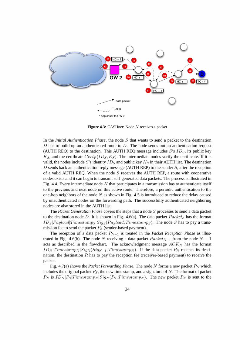
In the receiver’s network (numbered actions in Fig. 4.3) the intermediate nodes forward thepacket towards the destinationD (actions 13, 16, 19, 22). The nodes in the receiver’s networkacknowledge the reception of the forwarded packet to their precursors (actions 14, 17, 20, 23).The precursors earn Helper Credits when they receive the ACK message (actions 15, 18, 21, 24).But there, the receiver of the packet has to pay the costs for the packet proportional to the hopcount in order to receive the packet (action 25).
The operation process of CASHnet is divided in six different phases. They are shown for amulti-hop cellular network that belongs to providerP . In theSetup Phase, the nodeN has toperform the following tasks to be able to participate in the network:
1. The node needs to get a personal tamper resistant device (e.g. smart card) from theprovider P . The device contains the nodeN ’s uniqueIDN , the public / private keypair KN /KPN , a certificateCertP (IDN ,KN ) issued by the providerP , and the publickeyKP of the providerP . This task is only performed once.
2. If necessary, the nodeN ’s certificateCertP (IDN ,KN ) has to be updated.
3. If necessary, the Traffic Credit account has to be loaded. This can by done at the providerP ’s service station either by paying with real money and/or by trading Helper Credits.
23
GW 2 D
data packet
ACK
* hop count to GW 2
TC - 4*
12 13
1415
1618
17
25
19
20
21
22
23
24
HC + 1
HC + 1
HC + 1
HC + 1
Figure 4.3: CASHnet: NodeN receives a packet
In the Initial Authentication Phase, the nodeS that wants to send a packet to the destinationD has to build up an authenticated route toD. The node sends out an authentication request(AUTH REQ) to the destination. This AUTH REQ message includesS’s IDS , its public keyKS , and the certificateCertP (IDS ,KS). The intermediate nodes verify the certificate. If it isvalid, the nodes includeS’s identityIDS and public keyKS in their AUTH list. The destinationD sends back an authentication reply message (AUTH REP) to the senderS, after the receptionof a valid AUTH REQ. When the nodeS receives the AUTH REP, a route with cooperativenodes exists and it can begin to transmit self-generated data packets. The process is illustrated inFig. 4.4. Every intermediate nodeN that participates in a transmission has to authenticate itselfto the previous and next node on this active route. Therefore, a periodic authentication to theone-hop neighbors of the nodeN as shown in Fig. 4.5 is introduced to reduce the delay causedby unauthenticated nodes on the forwarding path. The successfully authenticated neighboringnodes are also stored in the AUTH list.
ThePacket Generation Phasecovers the steps that a nodeS processes to send a data packetto the destination nodeD. It is shown in Fig. 4.6(a). The data packetPacketS has the formatIDS |Payload|TimestampS |SigS(Payload, T imestampS). The nodeS has to pay a trans-mission fee to send the packetPS (sender-based payment).
The reception of a data packetPN−1 is treated in thePacket Reception Phaseas illus-trated in Fig. 4.6(b). The nodeN receiving a data packetPacketN−1 from the nodeN − 1acts as described in the flowchart. The acknowledgment messageACKN has the formatIDN |TimestampN |SigN (SigN−1, T imestampN ). If the data packetPN reaches its desti-nation, the destinationR has to pay the reception fee (receiver-based payment) to receive thepacket.
Fig. 4.7(a) shows thePacket Forwarding Phase. The nodeN forms a new packetPN whichincludes the original packetPS , the new time stamp, and a signature ofN . The format of packetPN is IDN |PS |TimestampN |SigN (PS , T imestampN ). The new packetPN is sent to the
24
GW 1 GW 2
senderS
destinationD
AUTH Request
AUTH Reply
Figure 4.4: CASHnet: Building up an authenticated path between the nodesS andD
GW 1
AUTH Request
AUTH Reply
Figure 4.5: CASHnet: Periodic authentication to one-hop neighbors
next hop toward the destinationD.Finally, the cooperative nodes receive their benefit in theRewarding Phase. The reward is
added to their Helper Credit account. These Helper Credits can be traded against Traffic Creditsat a service station of the providerP . To guarantee authorized reward only, the acknowledgmentmessagesACKN+1 are signed, and the pair< SigN (PN ), IDN+1 > must be included in thereward list of the node. The reward list is protected by the tamper resistant device.
4.3.2 Nuglet
The Nuglet scheme [19] offers decentralized accounting and security mechanisms in MANETs.It provides sender-based payment. In contrast to the CASHnet scheme, where cooperative nodescan save money, it forces the nodes to cooperate by making the ability to send own packetsdependent on the cooperativeness of the node. A node has to forward packets for the benefit ofothers in order to get credits to send self-generated packets.
25
?
?
P is ad-hoc only traffic
Calculate Transmission Fee
Yes
No
Transmission Fee <= TCSNo
Queue P
TCS - Transmission Fee
Form and transmit PS to N + 1
Yes
(a) Packet Generation Phase
?
?
NoSigN-1 and SigS from PN-1 valid
No ?
No
YesDiscard PN-1
PN-1 != ad hoc only traffic &&N == D
Yes
Calculate Reception Fee
TCN - Reception Fee
Send ACKN to N-1
PN-1 != ad hoc only traffic &&N-1 != S
Yes
Send ACKN to N-1
Packet Forwarding Phase
(b) Packet Reception Phase
Figure 4.6: CASHnet: Phases I
Nuglet requires the following components:
• A tamper resistant security module A, e.g. a smart card or a cryptographic coprocessor[25], that offers a protected environment for the routing and the Nuglet functions. Itcontains a credits counter, so calledNuglets counter(nc), the public / private key pair ofthe node, a certificateCertA, the manufacturer’s certificateCertM , a list of all certificatesof manufacturer’s of such security modules (assumption that only a few of them exists),the unique identifier of the security moduleIDA, a protected database of the securityassociations, a list with thepending counterspcX@A for each neighbor node.
• A routing algorithm, that allows estimation about the number of intermediate nodes to-ward a destination. It runs in the protected environment of the security module.
Nuglet’s operation is based on the following two rules (see example in Fig. 4.8) :
• When a node wants to send self-generated packets, it has to pay for them with Nuglets.The costs of a packet are the estimated number of intermediate nodes (ni) on the route tothe destination. The costs of a transmission (ni) are subtracted form theNuglets counter
26
Node N retrieves PS encapsulated in PN-1
Form PN
Get next hop N+1 in routing table towards R
Save <SigN(PN), IDN+1> in reward list
Transmit PN to next hop N+1
(a) Packet Forwarding Phase
?
?
NoSigN+1 from ACKN+1 valid
No
Yes
Discard PN-1
Yes
HCN + reward
<SigN(PN), IDN+1> in reward list
Remove <SigN(PN), IDN+1> from reward list
Discard PN-1
(b) Rewarding Phase
Figure 4.7: CASHnet: Phases II
data packet
S1
6
5
4
3
2
7
8
PCI@J + 1
NC - 3*
* number of intermediate nodes to destination D
I
KJ
D
PCJ@K + 1
PCK@D + 1
Figure 4.8: Nuglet: NodeS sends a packet to the destination nodeD.
(nc). Because thenc can not be negative, a node can only send an own packet, if thencis greater than or equal toni. Otherwise, the packet cannot be sent, and thenc stays thesame.
• By forwarding other nodes’ packets, a node can gain Nuglets, i.e. increase itsnc. These
27
Nuglets are not credited directly to thenc, they are store in the next node’spending counter(pcN@N+1) and periodically transmitted by a synchronization protocol.
Of course, the stimulation mechanism of Nuglet has to be protected against different attacks.Nobody should be able to manipulate theNuglets counter, especially increasing it. Further, itmust be ensured that theNuglets counteris only increased if the forwarding packet is reallyforwarded. The manipulation of theNuglets counteris prevented by using the above mentionedsecurity module. All critical functions are included in it. It is ensured that the node cannot gainany advantages by the manipulation of unprotected functions. The rewarding is ensured by theusage of thepending counters.
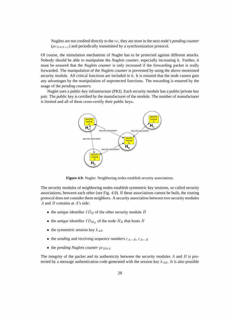
Nuglet uses a public-key infrastructure (PKI). Each security module has a public/private keypair. The public key is certified by the manufacturer of the module. The number of manufactureris limited and all of them cross-certify their public keys.
The security modules of neighboring nodes establish symmetric key sessions, so called securityassociations, between each other (see Fig. 4.9). If these associations cannot be built, the routingprotocol does not consider them neighbors. A security association between two security modulesA andB contains atA’s side:
• the unique identifierIDB of the other security moduleB
• the unique identifierIDHBof the nodeHB that hostsB
The integrity of the packet and its authenticity between the security modulesA andB is pro-tected by a message authentication code generated with the session keykAB. It is also possible
28
to provide a link-by-link encryption by usingkAB. Packet replay attacks are detected by the us-age of the increasing sequence numberscB→A, cA←B, cB→A, andcB←A. The establishment ofthe security association is done by using some public-key cryptographic protocol. The hostingnodes of the security modules run this protocol.
The operation of Nuglet is divided into different phases in order to easily compare it withthe CASHnet scheme. TheSetup Phaseconsists of getting a security module with the corre-sponding keys and certificates from a manufacturer. In the Authentication Phase, the securityassociations are built up. ThePacket Generation Phase, the Packet Reception Phaseand thePacket Forwarding Phaseare illustrated in Fig. 4.10(a), 4.10(b) and 4.11(a).
?
Node HA pass packet P to its security module A
Packet Forwarding Phase
A estimates the number of intermediate hops (ni) to destination
NC ≥ ni
Yes
No
Discard P
(a) Packet Generation Phase
A determines next security module B
A retrieves security association to B of its internal database
The cooperative nodes in the network receive their credits in the periodically executedNugletSynchronisation Phase(see Fig. 4.11(b), 4.12). The Nuglets inpending countersstored in thesecurity association of a node are transmitted to their owners. This concept is introduced toensure that the packets are really forwarded.
29
HB receives P + passes it to its security module B
B takes IDA + retrieves the security association of its internal database
?
?
Discard P
No
No
Yes
Yes
cA→B valid (packet replay prevention)
h(kAB; IDA, IDB, cA→B, P) valid
cB←A = cA→B
? Node HA is the originator of P
Packet Forwarding Phase
Yes
No
? Node HB is the destination of P
B pass the packet P to HBNo
Yes
pcA@B + 1
(a) Packet Reception Phase
?
Periodically the security module N of the node HN determines all neighbor node X with a non-zero pcX@N
Pending counters of all security associations are reseted to 0.
SYNC message valid
Yes
No
Discard SYNC
N sends to all of them a SYNC message containing the value of the corresponding pcX@N
If HX receives the SYNC, it pass the message to its security module X. If not, the nuglets are lost.
ncX + pcX@N (from the SYNC message)
(b) Packet Synchronisation Phase
Figure 4.11: Nuglet: Phases II
30
1
2
PCI@J = 1
KJ
I
Q
R PCR@J = 2
PCQ@J = 6SYNC(2)
SYNC(1)
SYNC(6)
NC + 2
NC + 1
NC + 6
2
2
3
3
3
Figure 4.12: Nuglet: NodeN submits thepending counterspcX@N in SY NC messages to their owners.
31
Chapter 5
Implementation of Simulation Model
This chapter describes the network simulator 2 (ns2) [15], its tracing mechanism and especiallythe wireless model in ns2. In addition, a closer look to the used Random Way Point Mobilitymodel is taken. Finally, the implementations of CASHnet and Nuglet in ns2 are discussed.
5.1 Background and Requirements
In order to verify the CASHnet cooperation scheme an implementation in a network simulatoris chosen. The alternative of an implementation in a real system (e.g. Linux) and testing it asexperimentation would use too much resources and finally be too expensive. Furthermore, theimplementation in a simulator offers more flexibility and variations, i.e. scenarios with muchmore nodes can be tested and adapted for the initial parameter tuning. An implementation inreal systems can be considered, if the verification with the help of the simulation is successful.A network simulator for the verification of the cooperation schemes should fulfill the followingrequirements:
• Simulation scenarios with 50 and more nodes.
• Gateways which are able to route packets between the wired and the wireless networks.
• Ad-hoc routing protocol that can supply the hop count for the cooperation scheme (CASH-net or Nuglet).
• Ad-hoc routing protocol that is able to detect the gateways.
• Physical Layer model with Radio Propagation.
• MAC Layer and Link Layer models.
• Mobility of the nodes.
• Enhanced tracing functionality.
There exists quite a number of network simulators today. Not all of them have a good reputationwithin the research community, and of those which have, most are expensive. Therefore, ns2
33
[15] is chosen, because it is open source software, freely available and it is widely used in theresearch community. Besides, ns2 meets perfectly the requirements. The protocol stack forMANET and multi-hop cellular networks is implemented. With AODV+ [13], there exists alsoa mobile ad-hoc routing protocol that is aware of gateways.
5.2 Implementation with Network Simulator 2
Ns2 [15] is a discrete event driven simulator. The source code and the documentation [26] arecurrently maintained by the Virtual Internet Testbed (VINT) at the Information Sciences Institute(ISI) of the University of Southern California (USC). The goal of ns2 is to support networkingresearch and education. It provides an environment for protocol design, traffic studies and pro-tocol comparison. Its license model enables the sharing of code, protocols, models, and ensuresthat the work is given back to the community. It allows easy comparison of similar protocols.This collaborative environment and the big number of users should also increase the confidencein the results because more people look at the models in more situations than by using a closedsource simulator.
5.2.1 Structure of ns2
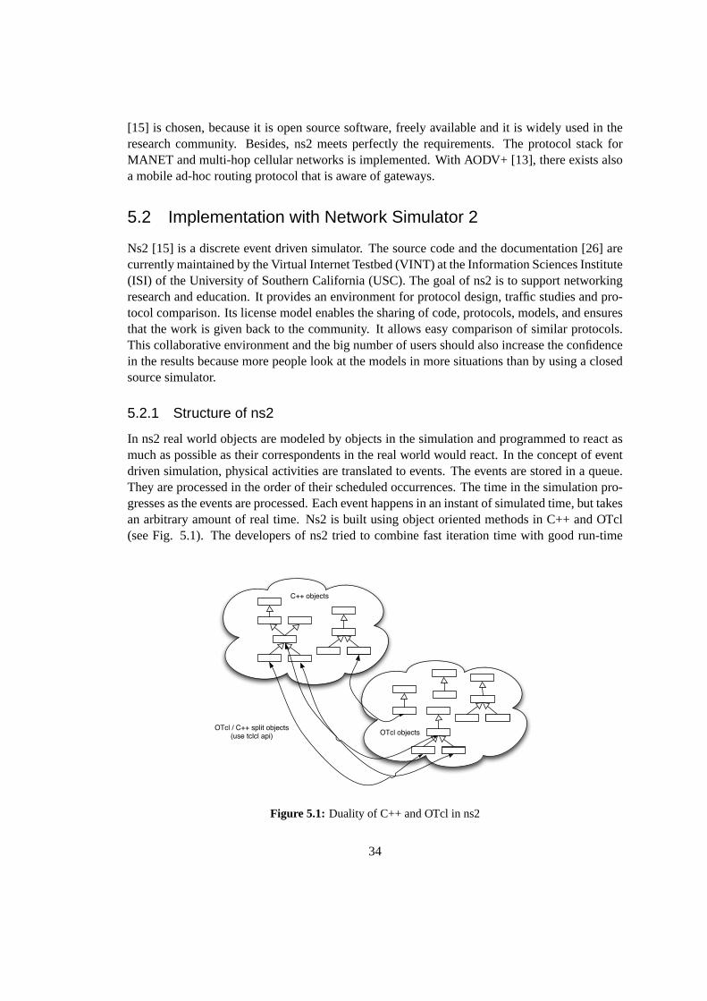
In ns2 real world objects are modeled by objects in the simulation and programmed to react asmuch as possible as their correspondents in the real world would react. In the concept of eventdriven simulation, physical activities are translated to events. The events are stored in a queue.They are processed in the order of their scheduled occurrences. The time in the simulation pro-gresses as the events are processed. Each event happens in an instant of simulated time, but takesan arbitrary amount of real time. Ns2 is built using object oriented methods in C++ and OTcl(see Fig. 5.1). The developers of ns2 tried to combine fast iteration time with good run-time
C++ objects
OTcl objectsOTcl / C++ split objects(use tclcl api)
Figure 5.1: Duality of C++ and OTcl in ns2
34
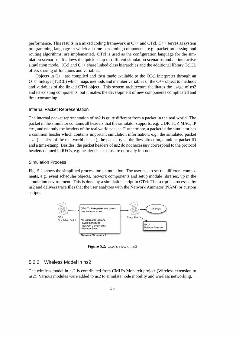
performance. This results in a mixed coding framework in C++ and OTcl. C++ serves as systemprogramming language in which all time consuming components, e.g. packet processing androuting algorithms, are implemented. OTcl is used as the configuration language for the sim-ulation scenarios. It allows the quick setup of different simulation scenarios and an interactivesimulation mode. OTcl and C++ share linked class hierarchies and the additional library TclCLoffers sharing of functions and variables.
Objects in C++ are compiled and then made available to the OTcl interpreter through anOTcl linkage (TclCL) which maps methods and member variables of the C++ object to methodsand variables of the linked OTcl object. This system architecture facilitates the usage of ns2and its existing components, but it makes the development of new components complicated andtime-consuming.
Internal Packet Representation
The internal packet representation of ns2 is quite different from a packet in the real world. Thepacket in the simulator contains all headers that the simulator supports, e.g. UDP, TCP, MAC, IPetc., and not only the headers of the real world packet. Furthermore, a packet in the simulator hasa common header which contains important simulation information, e.g. the simulated packetsize (i.e. size of the real world packet), the packet type, the flow direction, a unique packet IDand a time-stamp. Besides, the packet headers of ns2 do not necessary correspond to the protocolheaders defined in RFCs, e.g. header checksums are normally left out.
Simulation Process
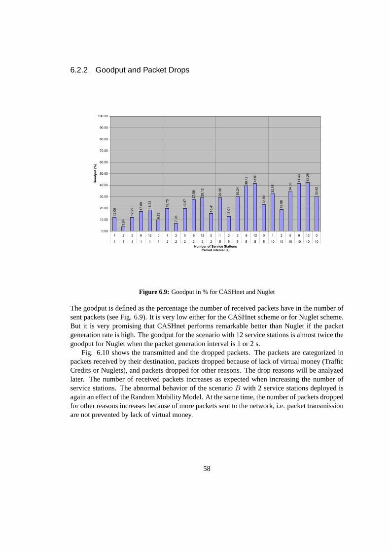
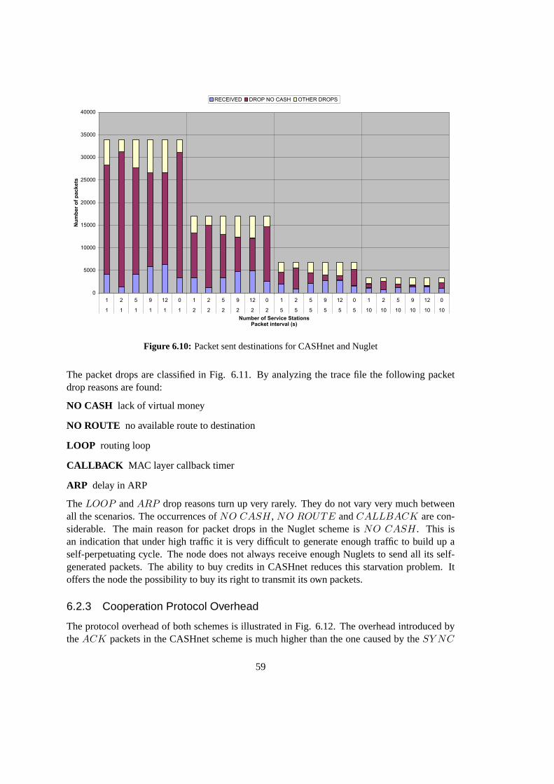
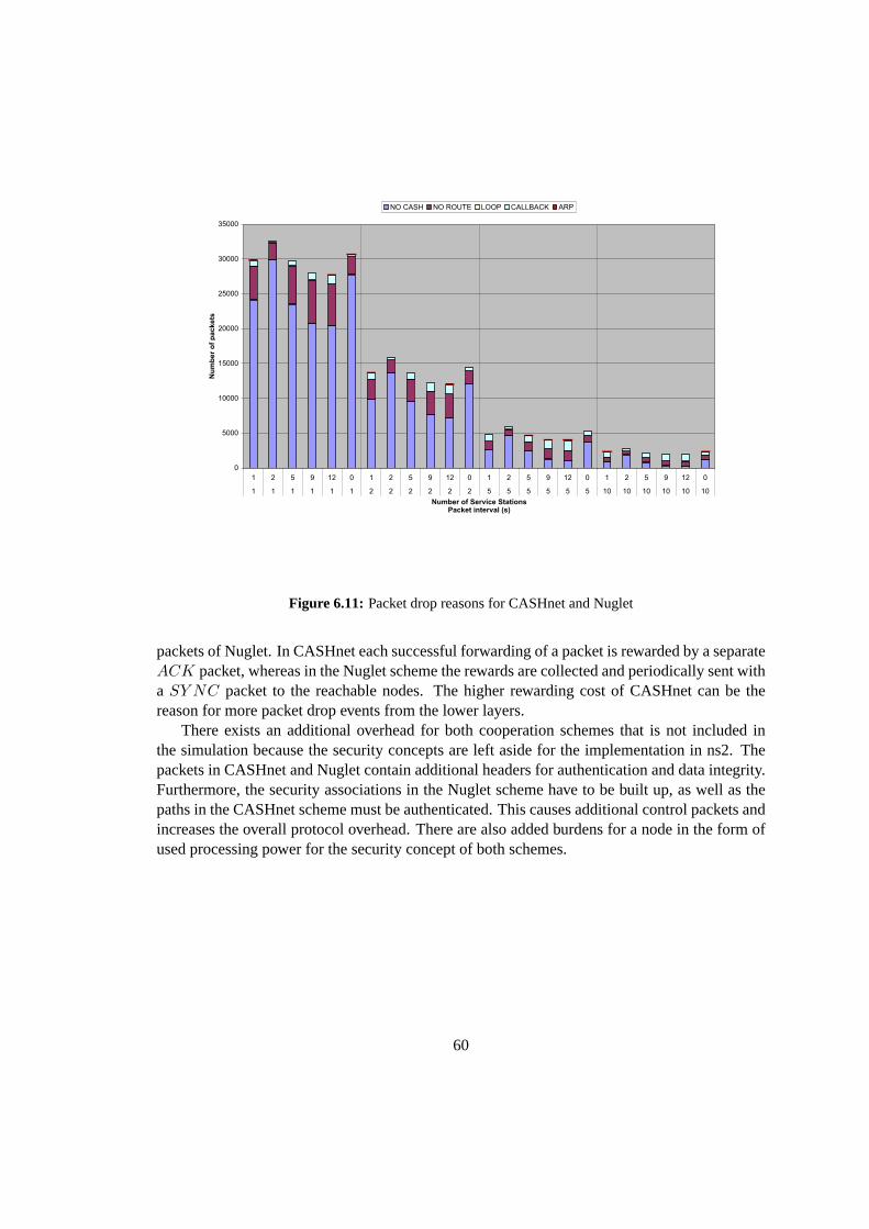
Fig. 5.2 shows the simplified process for a simulation. The user has to set the different compo-nents, e.g. event scheduler objects, network components and setup module libraries, up in thesimulation environment. This is done by a simulation script in OTcl. The script is processed byns2 and delivers trace files that the user analyzes with the Network Animator (NAM) or customscripts.
OTcl: Tcl interpreter with object-oriented extensions
The wireless model in ns2 is contributed from CMU’s Monarch project (Wireless extension tons2). Various modules were added to ns2 to simulate node mobility and wireless networking.
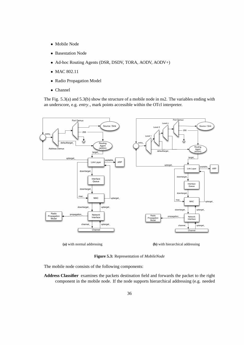
The Fig. 5.3(a) and 5.3(b) show the structure of a mobile node in ns2. The variables ending withan underscore, e.g.entry , mark points accessible within the OTcl interpreter.
Interface Queue
Link Layer
MAC
Network Interface
ARP
Channel
Radio Propagation
Model
Routing Agent
(AODV)
Source / Sink
255entry_
uptarget_
uptarget_
uptarget_channel_
propagation_
uptarget_downtarget_
downtarget_
downtarget_
mac_
arptable_
target_
defaulttarget_
Address Demux
Port Demux
(a) with normal addressing
Interface Queue
Link Layer
MAC
Network Interface
ARP
Channel
Radio Propagation
Model
Routing Agent
(AODV)
Source / Sink
255
entry_
uptarget_
uptarget_
uptarget_channel_
propagation_
uptarget_downtarget_
downtarget_
downtarget_
mac_
arptable_
target_
defaulttarget_
Level 1
Port Demux
Level 2
Level n
(b) with hierarchical addressing
Figure 5.3: Representation ofMobileNode
The mobile node consists of the following components:
Address Classifier examines the packets destination field and forwards the packet to the rightcomponent in the mobile node. If the node supports hierarchical addressing (e.g. needed
36
in multi-hop cellular networks), the address classifying component consists of multipleaddress classifiers (see Fig. 5.3(b)).
Port Classifier classifies the packets destination port and forwards the packet to the correctreceiving Agent on a node, e.g. AODV control packets are forwarded to port 255 wherethe AODV routing agent is listening.
Agent is responsible for packet generation and reception, similar to an application layer pro-gram. There exist various Agents such as CBR (Constant Bit Rate), TCP, FTP, etc.
Link Layer runs the link layer protocols. It fragments and reassembles the packets. It runs theAddress Resolution Protocol (ARP) to resolve IP addresses to MAC addresses.
Interface Queue gives priority to routing protocol packets.
MAC (Media Access Control) is implemented as IEEE 802.11 protocol.
Network Interface is the hardware interface used by the mobile node to access the wirelesschannel. Here the signal integrity, collisions, and transmission errors are simulated. Eachtransmitted packet is marked with transmission power, wavelength etc.
Radio Propagation Model uses Friss-space attenuation (1/r2) at near distance and Two RayGround Model (1/r4) at far distance. It implements an omni-directional antenna whichhas an unity gain for all directions. It checks if an simulated packet can be received withthe transmission power and wavelength set in the packet and the given distance to thesender of the packet.
Channel takes packets from the network interface and copies them to all other network inter-faces.
The mobile nodes are configured using the followingnode-configinterface.
$ns node−conf ig −addressType f l a t / h i e r a r c h i c a l−adhocRouting DSDV/DSR/TORA/AODV− l lType−macType−propType− ifqType− ifqLen−phyType−antType−channel−channelType− t opo logy Ins tance−wiredRouting ON/ OFF−mobileIP ON/ OFF−energyModel ” EnergyModel ”− i n i t i a l E n e r g y ( i n J o u l e s )−rxPower ( i n W)−txPower ( i n W)− idlePower ( i n W)−agentTrace ON/ OFF− rou te rTrace ON/ OFF−macTrace ON/ OFF−movementTrace ON/ OFF
37
5.2.3 Tracing
Ns2 offers tracing of all packets in the simulation. Furthermore, ns2 enables the tracing ofvariables in C++ or OTcl and supports the monitoring of queues and flows (see [26] for detailedinformation). In this thesis only the packet tracing ability is used. There exist three differenttrace file formats (old, new wiresslessandNAM) for packet tracing. [27] gives a good overviewof them. In this thesis the trace files are generated in the new wireless trace format. The newwireless trace format is defined in the source filestrace/cmu − trace.{h | cc}. The usage ofthe new trace file format requires the following lines in the simulation script:
$ns use−newtraces e t t r a c e f i l e [open<pa th o f t r a c e f i l e> w]$ns t r a c e−a l l $ t r a c e f i l e
A line of the trace file starts with an action flag (see Tab. 5.1(a)) which specifies the action thatthe node has performed on the packet. Then multiple flag / value pairs follow. A value flagconsists of a−, followed by one character indicating the type (see Tab. 5.1(b)) and one or twoadditional characters (Tab. 5.2, 5.3).
s sendr received dropf forward
(a) Action flags specify the action that wasprocessed to the packet
N Node PropertyI IP Level Packet InformationH Next Hop InformationM MAC Level Packet InformationP Application Level Packet Information
(b) Flag types for the new wireless traceformat
Table 5.1: New wireless trace format part I
Example
Four lines are picked of a trace file as an illustration (see listing 5.1 on p. 38). The first lineshows a reception of a constant bit rate (CBR) packet at node2. The second line illustrates thesending of a CBR packet at the time 71.01. In line 3 an AODVRREQ packet is dropped at node8 because of an expiredTTL field (-Iv 0, drop reason-Nw TTL). Finally, the line 4 describes aforwarded AODVRREP packet at the node18.
Listing 5.1: Four Example lines of a trace file with the new wireless trace file formatr −t 46 .189458524−Hs 2 −Hd 8 3 8 8 6 0 8−Ni 2 −Nx 1500 .00 −Ny 400 .00 −Nz 0 .00 −Ne −1.000000−Nl AGT −Nw−−−−Ma 13 a −Md
s—r—d—f action type-t double Time-Ni int Node ID-Nx double X Coordinate-Ny double Y Coordinate-Ne double Node Energy Level-Nl string Trace Name (AGT, RTR ...)-Nw string Drop Reason-Hs int Node ID-Hd int Node ID For Next Hop-Ma hexadecimal Duration-Ms hexadecimal Source Ethernet Address-Md hexadecimal Destination Ethernet Address-Mt hexadecimal Ethernet Type-P string Application Type (arp, dsr, cbr, tcp, ...)
Table 5.2: New wireless trace format part II
Event Flag Type Value
ARP Trace -Po string Request or Reply-Pms int Source MAC Address-Ps int Source Address-Pmd int Destination MAC Address-Pd int Destination Address
AODV Trace -Pt hexadecimal Type-Ph int Hop Count-Pb int Broadcast ID-Pd int Destination-Pds int Destination Sequence Number-Ps int Source-Pss int Source Sequence Number-Pl double Lifetime-Pc string Operation (REQUEST, REPLY, ERROR, HELLO)
IP Trace -Is int.int Source Address and Port-Id int.int Destination Address and Port-It string Packet Type-Il int Packet Size-If int Flow ID-Ii int Unique ID-Iv int TTL Value
TCP Trace -Ps int Sequence Number-Pa int Acknowledgment Number-Pf int Number of Times Packet was forwarded-Po int Optimal Number of Forwards
CBR Trace -Pi int Sequence Number-Pf int Number of Times Packet was forwarded-Po int Optimal Number of Forwards
Table 5.3: New wireless trace format part III
39
5.3 Random Waypoint Mobility Model
The Random Waypoint Mobility Model is used to model the movements of the mobile nodes inthe simulations in this thesis. This mobility model functions as follows. A mobile node beginsthe simulation by waiting a specified pause-time. After this time it selects a random destinationin the area and a random speed distributed uniformly between0 m/s andVmax. After reachingits destination point, the mobile node waits again pause-time seconds before choosing a newway point and speed.T. Camp, J. Boleng, and V. Davies: Survey of Mobility Models 5
0
100
200
300
400
500
600
0 50 100 150 200 250 300
Figure 3: Traveling pattern of an MN using the Random Waypoint Mobility Model.
If the specified time (or specified distance) an MN moves in the Random Walk Mobility Model is short, then themovement pattern is a random roaming pattern restricted to a small portion of the simulation area. Some simulationstudies using this mobility model (e.g., [2, 10]) set the specified time to one clock tick or the specified distance toone step. Figure 2 illustrates the static nature obtained in the Random Walk Mobility Model when the MN is allowedto move 10 steps (not one) before changing direction; as shown, the MN does not roam far from its initial position.In summary, if the goal of the performance investigation is to evaluate a semi-static network, then the parameter tochange an MN’s direction should be given a small value. Otherwise, a larger value should be used.
2.2 RandomWaypoint2.2.1 Overview
The Random Waypoint Mobility Model includes pause times between changes in direction and/or speed [16]. AnMN begins by staying in one location for a certain period of time (i.e., a pause time). Once this time expires, theMN chooses a random destination in the simulation area and a speed that is uniformly distributed between [minspeed,maxspeed]. The MN then travels toward the newly chosen destination at the selected speed. Upon arrival, the MNpauses for a specified time period before starting the process again.
Figure 3 shows an example traveling pattern of an MN using the Random Waypoint Mobility Model starting at arandomly chosen point or position (133, 180); the speed of the MN in the figure is uniformly chosen between 0 and10 m/s. We note that the movement pattern of an MN using the Random Waypoint Mobility Model is similar to theRandom Walk Mobility Model if pause time is zero and [minspeed, maxspeed] = [speedmin, speedmax].
The Random Waypoint Mobility Model is also a widely used mobility model (e.g., [4, 8, 11, 15]). In addition, themodel is sometimes simplified. For example, [18] uses the Random Waypoint Mobility Model without pause times.
2.2.2 Discussion
In most of the performance investigations that use the Random Waypoint Mobility Model, the MNs are initiallydistributed randomly around the simulation area. This initial random distribution of MNs is not representative of themanner in which nodes distribute themselves when moving. Figure 4 illustrates the cumulative average MN neighborpercentage for MNs using the Random Waypoint Mobility Model as time progresses (speed is 1 m/s and pause time
Figure 5.4: Traveling pattern of a mobile node using Random Waypoint Model (Fig. copied from [1])
The mobile nodes are initially distributed over the simulation area. This distribution is notrepresentative to the final distribution caused by node movements. To ensure a random initialconfiguration for each simulation, it is necessary to register the simulation after some time haselapsed.
The Random Waypoint Mobility Model is very frequently used in simulation studies ofMANET. As described in [28] the performance measurements in mobile ad-hoc networks areaffected by the used mobility model. One of the most important parameters in mobile ad-hocsimulations is the nodal speed. The users of the simulator want to adjust the average speed tobe stabilized around a certain value and not to change over time. They also want to be able tocompare the performance of the mobile ad-hoc routing protocols under different nodal speeds.For the Random Waypoint Mobility Model a common expectation is that the average is abouthalf of the maximum, because the speeds in a Random Waypoint Model are chosen uniformlybetween 0 m/s andVmax. The studies in [28] contradict this expectation and show that theaverage speed is decreasing over time and will approach 0.
This phenomenon can be intuitively explained as follows. In the Random Waypoint MobilityModel a node selects its destination and its speed. The node keeps moving until it reaches itsdestination at that speed. If it selects a far destination and a low speed around 0 m/s, it travels
40
for a long time with low speed. If it selects a speed nearVmax the time traveling with this highspeed will be short. After a certain time the node has traveled much more time at low speedthan at high speed. The average speed will approach 0 m/s. The suggestion in [28] to preventthis problem is choosing 1 m/s instead of 0 m/s asVmin. With this approach the average speedstabilizes after a certain time at a value below1/2 ∗ Vmax.
5.4 CASHnet Implementation
A simplified CASHnet scheme without the security mechanism, but with the full charging andrewarding functionality, has been implemented in ns2. Because of the mixed coding in ns2, it israther difficult to overview the internal packet flow in ns2. Methods and variables can be definedin C++ and made available to the OTcl interpreter. In addition, the source code is not well struc-tured and the multiple inheritances in C++ complete the confusion. It is also very difficult andtime-consuming to investigate in which files of the source code certain functionalities are imple-mented. But finally, the implementation becomes feasible with the help of the ns documentation[26] and the C++ class hierarchy on the ns2 web page.
Because there are similarities between the CASHnet and the Nuglet scheme a common superclass namedCooperationNodeis generated. It extends theMobileNodeclass and provides thecommon interface forCashnetNodeandNugletNode(see Fig. 5.5). Fig. 5.6 shows the structureof CashnetNode.
Node
MobileNode
CooperationNode
CashnetNode NugletNode
RNode ParentNode
TclObject
Figure 5.5: Class Hierarchy ofCooperationNode, CashnetNodeandNugletNode
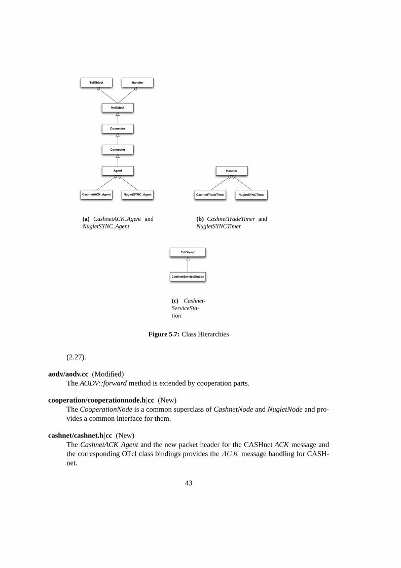
The new node for the CASHnet scheme contains an agent to handle theACK messages. TheCashnetACKAgent(Fig. 5.7(a)) sends and receives the new generatedACK messages.
The routing agent AODV from the AODV+ package is modified to be compatible to thens-2.27. In addition, it is enhanced to support cooperation in itsforward method by calling thesendPacketmethod of theCooperationNode.
41
Interface Queue
Link Layer
MAC
Network Interface
ARP
Channel
Radio Propagation
Model
Routing Agent(AODV+) with Cooperation
Source / Sink
entry_
uptarget_
uptarget_
uptarget_channel_
propagation_
uptarget_downtarget_
downtarget_
downtarget_
mac_
arptable_
target_
defaulttarget_
Level 1
Port Demux
Level 2
Level n
CashnetTradeTimer
CashnetACK_Agent
254
255
reward
Figure 5.6: Structure ofCashnetNode
The service-station of the CASHnet scheme is implemented with an additional class calledCash-netServiceStation(see Fig. 5.7(c)). It contains the location information of the service-station andprovides an interface for the creation in the OTcl interpreter (see Listing TCL interface). Thetrading mechanism of CASHnet, i.e. the purchasing of Traffic Credits with money or HelperCredits, consists of a static list of all service-stations, the methodtrade() of the CashnetNodeand the timer classCashnetTradeTimer(see Fig. 5.7(b)). TheCashnetTradeTimercalls thetrademethod of the node.tradechecks if the node is within trade distance of any service-station. If itis, the Helper Credits and real money are traded.
New and Modified Files
aodv/ (Replaced)The AODV package included in the standard ns2 package is replaced by the AODV+implementation of [13].
aodv/aodv.h (Modified)Some modifications are made to make AODV+ compatible with the newest version of ns2
42
TclObject Handler
NsObject
Connector
Connector
Agent
CashnetACK_Agent NugletSYNC_Agent
(a) CashnetACKAgent andNugletSYNCAgent
Handler
CashnetTradeTimer NugletSYNCTimer
(b) CashnetTradeTimerandNugletSYNCTimer
TclObject
CashnetServiceStation
(c) Cashnet-ServiceSta-tion
Figure 5.7: Class Hierarchies
(2.27).
aodv/aodv.cc (Modified)TheAODV::forwardmethod is extended by cooperation parts.
cooperation/cooperationnode.h|cc (New)TheCooperationNodeis a common superclass ofCashnetNodeandNugletNodeand pro-vides a common interface for them.
cashnet/cashnet.h|cc (New)TheCashnetACKAgentand the new packet header for the CASHnetACK message andthe corresponding OTcl class bindings provides theACK message handling for CASH-net.
43
cashnet/cashnetnode.h|cc (New)The CashnetNodeclass provides the charging and rewarding mechanisms of CASHnet.The class constructor and certain member variables are bound to OTcl space. That is theway to be able to generate a CashnetNode in OTcl space. In addition, further OTcl shellcommands can be defined inCashnetNode::commandmethod. Moreover, theCashnet-TradeTimerclass provides a timer which is used to periodically start the trading mecha-nisms.
cashnet/servicestation.h|cc (New)TheCashnetServiceStationclass models the service station for CASHnet and contains astatic list of allCashnetServiceStationobjects to support the trading process.
common/agent.h|cc (Modified)The member variablesnode andcooperative are added and bound to the correspondingOTcl variables. This makes it possible for the agent to find the node, to which it is attached,otherwise there is no possibility to get a reference to the node in C++ because the agentsare attached to the node in the OTcl space. This is a common problem in ns2.
common/packet.h (Modified)A new method is defined to access directly the header of the CASHnetACK message.PT CASHNETACKis added as new packet type.
trace/cmu-trace.h (Modified)NO CASHis defined as new reason for packet drops at nodes with not enough credits tosend the packet at the wished destination.
trace/cmu-trace.cc (Modified)The trace format for the new CASHnet acknowledge message is defined and integrated intheformatmethod.
routing/address.h|cc (Modified)A new method decides whether two addresses are in the same hierarchical subnet or not.
tcl/lib/ns-default.tcl (Modified)Here the default values of the variables accessible in the OTcl interpreter are set.
tcl/lib/ns-lib.tcl (Modified)A new cooperation flag is added to thenode-configinterface.
Makefile.in (Modified)Here the new classes are included in the ns2 make process.
OTcl Interface
In order to keep the configuration of the CASHnet scheme simple, thenode-configinterface isenhanced and all options can be set in the simulation script. The listing 5.2 shows the OTclinterface enhancement for CASHnet.
44
Listing 5.2: OTcl Interface Extensions for CASHnet$ns node−conf ig −cooperat ion ”CASHNET”
$node ( 1 ) s e t c o o p e r a t i v e t r u e ;# S e t s t h e node c o o p e r a t i v e ( t r u e| f a l s e )$node ( 1 ) s e t T r a f f i c C r e d i t s 500 ;# Amount o f T r a f f i c C r e d i t s$node ( 1 ) s e t RealMoneyAccount 500 ;# How much r e a l money does t h e node have ?$node ( 1 ) s e t H e l p e r C r e d i t s 0 . 0 ;# Amount o f He lper C r e d i t s$node ( 1 ) s e t I n f i n i t M o n e y f a l s e ;# Never end ing money ? ( t r u e| f a l s e )$node ( 1 ) s e t ExchangeRate 1 ; # How many Helper C r e d i t s has t h e node t o pa idf o r one T r a f f i c
C r e d i t ?$node ( 1 ) s e t ExchangeAmount 20 . 0 ;# How many T r a f f i c C r e d i t s are t r a d e d a t onet ime ?$node ( 1 ) s e t T r a d e T h r e s h o l d 10 . 0 ;# I f t h e node has l e s s T r a f f i c C r e d i t s , i t t r i e s t o t r a d e .$node ( 1 ) s e t T r a d e D i s t a n c e = 50 . 0 ;# Wi th in t h i s d i s t a n c e t h e node can t r a d e T r a f f i c C r e d i t s .$node ( 1 ) s e t T r a d e I n t e r v a l = 1 . 0 ;# D e f i n e s t h e i n t e r v a l between t h e p e r i o d i c checksi f t h e node i s
near enough a s e r v i c e s t a t i o n
$ns a t 1 . 0 ” $node ( 1 ) t r a d e ” ;# S t a r t s t h e t r a d i n g mechanism o f CASHnet$ns a t 900 .01 ” $node( $ i ) moneyPaid ” ;# P r i n t s ou t t h e amount o f T r a f f i c C r e d i t s t h e node pa idf o r send ing
p a c k e t s$ns a t 900 .01 ” $node( $ i ) c r e d i t s T r a d e d ” ;# P r i n t s ou t t h e amount o f T r a f f i c C r e d i t s t h e node t r a d e d$ns a t 900 .01 ” $node( $ i ) c r e d i t s ” ;# P r i n t s ou t t h e c u r r e n t amount o f T r a f f i c C r e d i t s
5.5 Nuglet Implementation
Interface Queue
Link Layer
MAC
Network Interface
ARP
Channel
Radio Propagation
Model
Routing Agent(AODV+) with Cooperation
Source / Sink
entry_
uptarget_
uptarget_
uptarget_channel_
propagation_
uptarget_downtarget_
downtarget_
downtarget_
mac_
arptable_
target_
defaulttarget_
Level 1
Port Demux
Level 2
Level n
NugletSYNCTImer
NugletSYNC_Agent
254
255
reward
Figure 5.8: Structure ofNugletNode
45
The implementation of the Nuglet scheme is similiar to the one of CASHnet. A new subclass ofCooperationNodeis generated (Fig. 5.5). This newNugletNodeclass implements the chargingand rewarding mechanism of the Nuglet scheme. Its structure is shown in Fig. 5.8. It containsa NugletSYNCAgentobject (Fig. 5.7(a)) which handles theSY NC messages of Nuglet. Thecooperation mechanism is integrated in the AODV routing as formerly explained for CASHnet.TheNugletSYNCTimerperiodically starts the delivering of the pending Nuglets counterpcX@N
to the corresponding one-hop neighbor perSY NC message.
New and Modified Files
nuglet/nugletnode.h|cc (New)TheNugletNodeclass provides the charging and rewarding mechanisms of Nuglet. Theclass is bounded to OTcl similiar to theCashnetNode. Further, theNugletSYNCTimerpe-riodically calls theNugletNode::synchronizemethod to synchronize the pending counterpcX@N and send the Nuglets to the corresponding one-hop neighbor.
nuglet/nugletsync.h|cc (New)The agentNugletSYNCAgentand the new packet for theSY NC message are defined.The agent is responsible for the handling of theSY NC messages.
common/packet.h (Modified)A new method is defined to access directly the header of the NugletSY NC message. Inaddition, a new packet typePT NUGLETSYNCis added.
trace/cmu-trace.cc (Modified)A new format method for theSY NC is implemented.
Makefile.in (Modified)Here the new classes are included in the ns2 make process.
OTcl Interface
The node-configinterface is also enhanced for the Nuglet scheme and the options of Nugletcan be set in the simulation script. The listing 5.3 presents the OTcl interface enhancement forNuglet.
Listing 5.3: OTcl Interface Extensions for Nuglet$ns node−conf ig −cooperat ion ”NUGLET”
$node ( 1 ) s e t c o o p e r a t i v e t r u e ;# S e t s t h e node c o o p e r a t i v e ( t r u e| f a l s e )$node ( 1 ) s e t N u g l e t s 500 . 0 ;# Amount o f N u g l e t s$node ( 1 ) s e t SYNCInterva l 1 ; # D e f i n e s t h e i n t e r v a l between t h e p e r i o d i c send ing o f t h e SYNC
messages
$ns a t 1 . 0 ” $node ( 1 ) sync ” ;# S t a r t s t h e s y n c h r o n i z i n g mechanism o f Nug le t$ns a t 900 .01 ” $node( $ i ) moneyPaid ” ;# P r i n t s ou t t h e amount o f N u g l e t s t h e node pa idf o r send ing p a c k e t s$ns a t 900 .01 ” $node( $ i ) c r e d i t s T r a d e d ” ;# P r i n t s ou t t h e amount o f N u g l e t s t h e node r e c e i v e d$ns a t 900 .01 ” $node( $ i ) c r e d i t s ” ;# P r i n t s ou t t h e c u r r e n t amount o f N u g l e t s
46
Chapter 6
Evaluation
This chapter presents the simulation scenarios and their evaluations. The liveliness of the net-work for the CASHnet and the Nuglet schemes is measured. The amount and the frequency ofstarvation of individual nodes are used as the indicator. Furthermore, the packet drops and theresulting overhead are analyzed.
6.1 Simulation Scenarios
The two cooperation schemes CASHnet and Nuglet are evaluated using ns2 and their simplifiedimplementations. For the simulation scenarios only one multi-hop network is considered inorder to be compatible to the Nuglet scheme which is actually designed for MANET. Fig. 6.1presents the basic scenario for the test runs. Different simulation scenarios are made by varying
GW 1
Figure 6.1: Basic evaluation scenario for CASHnet and Nuglet
the amount of service stations and their distribution. Actually, the simulations run with 1, 2, 5, 9and 12 service stations equally distributed and with 9 or 12 service stations randomly distributed.Fig. 6.2 shows the used simulation scenarios. When the simulation is running with the Nugletscheme the service stations are removed and the gateway acts as a normal node in the MANET.Furthermore, the packet generation interval at the CBR traffic sources is varied (1, 2, 5, and 10 s).In total 32 (8 x 4) simulation scenarios are investigated and for each of them 20 simulation runsusing 20 independent movement files are performed. The simulation script for the CASHnettests is shown in the listings 6.3. The configurations of the service stations are included from a
47
Listing 6.1: Example service station files e t s e r v i c e S t a t i o n 1 [ new C a s h n e t S e r v i c e S t a t i o n ]$ s e r v i c e S t a t i o n 1 s e t X [ expr $va l (X) / 3 . 0 ]$ s e r v i c e S t a t i o n 1 s e t Y [ expr $va l (X) / 2 . 0 ]$ s e r v i c e S t a t i o n 1 s e t Z 0 . 0
s e t s e r v i c e S t a t i o n 2 [ new C a s h n e t S e r v i c e S t a t i o n ]$ s e r v i c e S t a t i o n 2 s e t X [ expr 2 ∗$val (X) / 3 . 0 ]$ s e r v i c e S t a t i o n 2 s e t Y [ expr $va l (X) / 2 . 0 ]$ s e r v i c e S t a t i o n 2 s e t Z 0 . 0
Listing 6.2: Example lines of a node movement file## nodes : 40 , speed t y p e : 1 , min s p e e d : 1 . 0 0 , max s p e e d : 10 .00# avg s p e e d : 3 . 6 7 , pause t y p e : 2 , pause : 10 . 0 0 , max x : 1500 . 0 0 , max y : 800 .00#$node ( 0 ) s e t X 1339 .865501781931$node ( 0 ) s e t Y 523 .560828552733$node ( 0 ) s e t Z 0 .000000000000. . .$ns a t 0 .000000000000 ” $node( 0 ) s e t d e s t 1347 .356779559099102 .3462391663383 .020117394902 ”$ns a t 0 .000000000000 ” $node( 1 ) s e t d e s t 603 .54990408252522 .7850518979347 .340209978810 ”. . .$god s e t−d i s t 0 1 4$god s e t−d i s t 0 2 3. . .$god s e t−d i s t 3 8 3 9 1$ns a t 0 .030803485331 ” $god s e t−d i s t 18 25 1 ”. . .$ns a t 223 .791821804280 ” $god s e t−d i s t 15 36 3 ”$ns a t 223 .797528851594 ” $node( 8 ) s e t d e s t 903 .090542727809531 .4335028031310 .000000000000 ”$ns a t 224 .101320059278 ” $god s e t−d i s t 10 14 2 ”$ns a t 224 .101320059278 ” $god s e t−d i s t 10 30 1 ”. . .ns a t 899 .839645853655 ” $god s e t−d i s t 18 23 2 ”$ns a t 899 .839645853655 ” $god s e t−d i s t 18 28 3 ”## D e s t i n a t i o n Unreachab les : 1829## Route Changes: 37291## L ink Changes: 3491## Node | Route Changes| L ink Changes# 0 | 2 0 7 3 | 120# 1 | 1 8 3 9 | 146. . .# 3 9 | 2 1 0 6 | 166
48
A B C
D E F
GGateway
Mobile Node
Service Station
Figure 6.2: Simulation scenarios with distribution of the service stations
separate file (see listing 6.1). Furthermore, the movements of the nodes are also included froman external file (Listing 6.2). This mobility file is generated using thesetdestprogram of thens2 package and provides movements according to the Random Waypoint Mobility Model. Themovement and service station files as well as the handing-over of parameters enable the reuse ofthe same simulation script for all of our CASHnet scenarios. The simulation script for Nuglet iscorresponding to the one of CASHnet. The table 6.1 shows the parameters for both schemes.
ValueParameterNuglet CASHnet
Initial balance of virtual money account 100 Nuglets 100 Traffic CreditsInitial balance of real money account – 500Nuglet synchronization interval 5s –Traffic / Helper Credits exchange rate – 1:1Exchange threshold at service stations – 10 Helper CreditsDistance threshold to service stations – 50 mNumber of service stations – 1, 2, 5, 9 or 12Simulation area 1500 m x 800 mNumber of mobile nodes 40Transmission range 250 mMobility model random mobilityNode speed uniformly distributed between 1 and 10 m/sPause time uniformly distributed between 0 and 20 sPacket generation interval 1, 2, 5, 10 sRouting AODV+Simulation time 900 s
Table 6.1: Simulation parameters
49
Listing 6.3: Simulation script for CASHnetproc g e t o p t { a rgc argv} {
g l o b a l op tlappend o p t l i s t movs f i l e s e r v i c e s t a t i o n s nn l nnr p a c k e t i n t e r v a lf o r { s e t i 0 } { $ i < $argc } { i n c r i } {
s e t arg [ l i n d e x $argv $ i ]i f { [ s t r i n g range $arg 0 0 ] ! = ”−” } con t inues e t name [s t r i n g range $arg 1 end ]s e t op t ( $name ) [l i n d e x $argv [expr $ i +1 ] ]
}}
proc s t o p {} {g l o b a l ns t r a c e f d$ns f l u s h− t r a c ec l o s e $ t r a c e f d
}
# Read command l i n e argsg e t o p t $a rgc $argv# ======================================================================# De f i ne o p t i o n s# ======================================================================s e t v a l ( prop ) P r o p a g a t i o n / TwoRayGround ;# rad io−propagat ion models e t v a l ( n e t i f ) Phy / Wi re lessPhy ;# network i n t e r f a c e types e t v a l ( mac ) Mac /802 11 ;# MAC types e t v a l ( i f q ) Queue / DropTa i l / Pr iQueue ;# i n t e r f a c e queue types e t v a l ( l l ) LL ; # l i n k l a y e r types e t v a l ( a n t ) Antenna / OmniAntenna ;# antenna models e t v a l ( i f q l e n ) 50 ;# max p a c k e t i n i f qs e t v a l ( nn l ) $op t ( nn l ) ;# number o f mob i lenodes i n l e f t areas e t v a l ( nnr ) $op t ( nnr ) ;# number o f mob i lenodes i n r i g h t areas e t v a l ( bsn ) 2 ;# number o f b a s e s t a t i o n ss e t v a l ( rp ) AODV ; # r o u t i n g p r o t o c o ls e t v a l ( T r a f f i c C r e d i t s ) 100 . 0 ;# s t a r t c r e d i t f o r a l l nodess e t v a l ( ExchangeRate ) 1 . 0 ;# exchange r a t e h e l p e r p o i n t s / t r a f f i c p o i n t ss e t v a l ( RealMoneyAccount ) 500 . 0s e t v a l (X) 1500s e t v a l (Y) 800
s e t ns [ new S i m u l a t o r ]$ns use−newtrace
s e t t r a c e f d [open $opt ( f i l e ) w]$ns t r a c e−a l l $ t r a c e f d
s e t topo [ new Topography ]$ topo l o a d f l a t g r i d [ expr 2 ∗ $va l (X) ] $va l (Y) ; # c r e a t e t o p o l o g y
s e t god [ create−god [ expr $va l ( nn l ) + $va l ( nnr ) + $va l ( bsn ) + 1 ] ]
#−−−−−−−−−Addressing−−−−−−−−−#$ns node−conf ig −addressType h i e r a r c h i c a lAddrParams s e t domain num 3AddrParams s e t c l u s t e r n u m {1 1 1}AddrParams s e t nodes num {1 41 41}Agent /AODV s e t gw d iscove ry 1
s e t r o u t e r 1 [ $ns node 0 . 0 . 0 ]
$ns node−conf ig −adhocRouting $va l ( rp )\− l lType $va l ( l l ) \−macType $va l ( mac )\− ifqType $va l ( i f q ) \− ifqLen $va l ( i f q l e n ) \−antType $va l ( a n t )\−propType $va l ( prop )\−phyType $va l ( n e t i f )\−channel [ new Channel / W i re l essChanne l ]\− topo Ins tance $topo\−agentTrace ON\− rou te rTrace ON\−macTrace OFF\−movementTrace OFF\−wiredRouting ON\−coopera t ion CASHNET
s e t gw1 [ $ns node 1 . 0 . 0 ]s e t gw2 [ $ns node 2 . 0 . 0 ]
$ns duplex− l ink $gw1 $ r o u t e r 1 100Mb 2 ms DropTa i l$ns duplex− l ink $ r o u t e r 1 $gw2 100Mb 2 ms DropTa i l
50
# Cre a t i on o f t h e mob i le nodes$ns node−conf ig −wiredRouting OFF
# Crea te mob i le nodesf o r s e c t o r 1f o r { s e t i 0} { $ i < $va l ( nn l )} { i n c r i } {
s e t node ( $ i ) [ $ns node 1 . 0 . [expr $ i +1 ] ]#puts ”\nNode $ i $node ( $ i ) [ $node ( $ i ) node−addr ] ”$node ( $ i ) random−motion 0$node ( $ i ) base−s ta t i on [ AddrParams a d d r 2 i d [ $gw1 node−addr ] ]$node ( $ i ) s e t c o o p e r a t i v e t r u e$node ( $ i ) s e t T r a f f i c C r e d i t s $va l ( T r a f f i c C r e d i t s )$node ( $ i ) s e t ExchangeRate $va l ( ExchangeRate )$node ( $ i ) s e t RealMoneyAccount $va l ( RealMoneyAccount )
}# Crea te mob i le nodesf o r s e c t o r 2f o r { s e t i 0} { $ i < $va l ( nnr )} { i n c r i } {
s e t node ( [ expr $ i + $va l ( nn l ) ] ) [ $ns node 2 . 0 . [expr $ i +1 ] ]$node ( [ expr $ i + $va l ( nn l ) ] ) random−motion 0$node ( [ expr $ i + $va l ( nn l ) ] ) base−s ta t i on [ AddrParams a d d r 2 i d [ $gw2 node−addr ] ]$node ( [ expr $ i + $va l ( nn l ) ] ) s e t c o o p e r a t i v e t r u e$node ( [ expr $ i + $va l ( nn l ) ] ) s e t T r a f f i c C r e d i t s $va l ( T r a f f i c C r e d i t s )$node ( [ expr $ i + $va l ( nn l ) ] ) s e t ExchangeRate $va l ( ExchangeRate )$node ( [ expr $ i + $va l ( nn l ) ] ) s e t RealMoneyAccount $va l ( RealMoneyAccount )
}
# p o s i t i o n s f o r g a t e w a y s , r o u t e r$gw1 s e t X 1490 . 0$gw1 s e t Y 400 . 0$gw1 s e t Z 0 . 0
$gw2 s e t X 1500 . 0$gw2 s e t Y 400 . 0$gw2 s e t Z 0 . 0
$ r o u t e r 1 s e t X 1495 . 0$ r o u t e r 1 s e t Y 400 . 0$ r o u t e r 1 s e t Z 0 . 0
# Get t h e s e r v i c e s t a t i o n ssource $opt ( s e r v i c e s t a t i o n s )
# Crea te c o n n e c t i o n s nodes o f s e c t o r 1−> gw2f o r { s e t i 0} { $ i < $va l ( nn l )} { i n c r i } {
s e t s r c ( $ i ) [ new Agent /UDP]s e t d s t ( $ i ) [ new Agent / Nu l l ]$ns a t tach−agen t $node( $ i ) $ s r c ( $ i )$ns a t tach−agen t $gw2 $ d s t( $ i )$ns connec t $ s r c ( $ i ) $ d s t ( $ i )$ s r c ( $ i ) s e t f i d 1s e t c b r ( $ i ) [ new A p p l i c a t i o n / T r a f f i c /CBR]$ c b r ( $ i ) s e t p a c k e t S i z e 512$ c b r ( $ i ) s e t i n t e r v a l $op t ( p a c k e t i n t e r v a l )$ c b r ( $ i ) a t tach−agen t $ s r c ( $ i )$ns a t 1 .01 ” $ c b r ( $ i ) s t a r t ”$ns a t 850 . 0 ” $ c b r ( $ i ) s t o p ”
}f o r { s e t i 0} { $ i < $va l ( nn l ) + $va l ( nnr )} { i n c r i } {
$ns a t 1 . 0 ” $node ( $ i ) t r a d e ”}# Impor t movement p a t t e r n ssource $opt ( movs )
f o r { s e t i 0} { $ i < $va l ( nn l ) + $va l ( nnr ) } { i n c r i } {$ns a t 900 . 0 ” $node( $ i ) r e s e t ” ;$ns a t 900 .01 ” $node( $ i ) moneyPaid ”$ns a t 900 .01 ” $node( $ i ) c r e d i t s T r a d e d ”$ns a t 900 .01 ” $node( $ i ) c r e d i t s ”
}$ns a t 900 . 0 ”$gw1 r e s e t ” ;$ns a t 900 . 0 ”$gw2 r e s e t ” ;$ns a t 900 .001 ” s t o p ”$ns a t 900 .01 ” $ns h a l t ”$ns run
51
6.2 Results
The discussion starts with the starvation properties of the CASHnet and the Nuglet scheme.Afterwards, the overall protocol performance and the protocol overhead are analyzed. The meanresults over the 20 simulation runs from 24 scenarios are combined by the Fig. 6.7, 6.9, 6.10,6.11, and 6.12. Each x-axis label consists of two lines. The first line codes the number of servicestations (1, 2, 5, 9, 12 for CASHnet and 0 for Nuglet). The used service station distributions areA, B, C, D, andE as presented in Fig. 6.2 on page 49. The second line indicates the packetgeneration interval (1, 2, 5, 10 s). In the figures the different packet generation intervals areseparated by vertical lines.
6.2.1 Starvation
The starvation describes the node’s inability to send self-generated packets due to the lack ofvirtual money (Traffic Credits or Nuglets). Fig. 6.3 presents the starvation periods of each nodeduring a single simulation run for 3 scenarios with a packet generation interval of 10 s. Thered lines indicates the starvation periods of the nodes. Because the nodes frequently cross thearea of a service station in scenarioE (Fig. 6.2 on page 49) and can trade Traffic Credits, thestarvation periods of the nodes are almost eliminated. The Nuglet scenario performs better asthe scenarioA, because with only one service station in the CASHnet scenario the probabilityof being able to trade credits is low and the rewarding mechanism of Nuglet is preferred. Thebehavior of the first ten nodes of scenarioE is additionally displayed in spatial way in Fig. 6.8.The transmission range of the gateway is marked as a semicircle as well as the service stationsare shown as circles. The nodes follow their paths beginning at the arrow. The starvation eventsare indicated by a cross with label with the format<B (begin) | E (end)><time><TrafficCredits><Helper Credits><real money>. The histograms in Fig. 6.5 sort the starvationevents according to their durations. A box represents the mean number of starvation events inthis duration category for the 20 simulation runs. Because a large number of long starvations isnormally much worse than many small starvations, the longer the starvation duration is (x-axis),the smaller the number of starvations should be (y-axis). The average number of nodes whichare starving for quite the complete simulation time is rather low for all scenarios. The scenariosF andG with the randomly distributed service stations perform worse than their correspondentscenariosD andE with aligned service stations. Long starvation periods occur more frequentlyfor them. Thus the equal distribution of the service stations raises their positive influence on theoverall network liveliness. Further, the effect of additional service stations flattens out with thenumber of them, i.e. the raise from 5 to 9 service stations brings more benefits than the raisefrom 9 to 12.
The histograms in Fig. 6.4 present the results for the scenariosB andE. The increasingof the number of service stations reduces the number of starvations and shortens the singlestarvation periods (see also Fig. 6.5). By increasing the sending rate in a scenario, e.g.E, witha high number of service stations, the number of starvation periods becomes higher. The highnumber of sent packets causes the nodes to run out of Traffic Credits faster. The probability ofstarving nodes grows. Due to the high number of service stations especially the amount of shortstarvations goes up. The nodes more often meet a service station and are more frequently able
52
1
3
5
7
9
11
13
15
17
19
21
23
25
27
29
31
33
35
37
39
0 100 200 300 400 500 600 700 800 900
Node number
Simulation time (s)
CASHnet, 10 s packet interval, 1 service station, run 0
Starvation period
(a) ScenarioA CASHnet
1
3
5
7
9
11
13
15
17
19
21
23
25
27
29
31
33
35
37
39
0 100 200 300 400 500 600 700 800 900
Node number
Simulation time (s)
CASHnet, 10 s packet interval, 12 service stations, run 0
Starvation period
(b) ScenarioE CASHnet
1
3
5
7
9
11
13
15
17
19
21
23
25
27
29
31
33
35
37
39
0 100 200 300 400 500 600 700 800 900
Node number
Simulation time (s)
Nuglets, 10 s packet interval, run 0
Starvation period
(c) Scenario Nuglet
Figure 6.3: Starvation periods for all nodes during a single simulation run
to trade credits than with a low density of service stations. For a scenario with a low number ofservice stations, e.g.B, the increasing of the packet generation rate has a different effect. Thelong starvation periods are mainly transformed in short ones. The nodes receive more HelperCredits because of the increased traffic and so can exchange more of them at the service station.
Fig. 6.7 illustrates the average starvation length for a node in CASHnet and Nuglet with atotal simulation time of 900 s. The two schemes CASHnet and Nuglet perform poorly underhigh network load. CASHnet is generally better than Nuglet, if there are at least five servicestations deployed. The CASHnet scheme performs worse with a low number of service stationsbecause the rewarding overhead is higher than for the Nuglet scheme (see section 6.2.3) andmoreover the healthy effect of trading credits is small with few service stations. If it is looked atthe results under low network load, CASHnet performs quite well in contrast to Nuglet. At firstsight, it is surprising that the values for scenarioB with two service stations are worse than for
Figure 6.4: Comparison of two CASHnet scenarios with two different packet generation intervals
scenarioA with one service station. The same is valid for the goodput as shown later in Fig. 6.9.This could be caused by the Random Waypoint Mobility Model. It leads in node paths whichhave a higher probability to go through the center of the simulation area. The nodes do not passat a service station frequently and therefore can not refill their Traffic Credits accounts.
The goodput is defined as the percentage the number of received packets have in the number ofsent packets (see Fig. 6.9). It is very low either for the CASHnet scheme or for Nuglet scheme.But it is very promising that CASHnet performs remarkable better than Nuglet if the packetgeneration rate is high. The goodput for the scenario with 12 service stations is almost twice thegoodput for Nuglet when the packet generation interval is 1 or 2 s.
Fig. 6.10 shows the transmitted and the dropped packets. The packets are categorized inpackets received by their destination, packets dropped because of lack of virtual money (TrafficCredits or Nuglets), and packets dropped for other reasons. The drop reasons will be analyzedlater. The number of received packets increases as expected when increasing the number ofservice stations. The abnormal behavior of the scenarioB with 2 service stations deployed isagain an effect of the Random Mobility Model. At the same time, the number of packets droppedfor other reasons increases because of more packets sent to the network, i.e. packet transmissionare not prevented by lack of virtual money.
Figure 6.10: Packet sent destinations for CASHnet and Nuglet
The packet drops are classified in Fig. 6.11. By analyzing the trace file the following packetdrop reasons are found:
NO CASH lack of virtual money
NO ROUTE no available route to destination
LOOP routing loop
CALLBACK MAC layer callback timer
ARP delay in ARP
TheLOOP andARP drop reasons turn up very rarely. They do not vary very much betweenall the scenarios. The occurrences ofNO CASH, NO ROUTE andCALLBACK are con-siderable. The main reason for packet drops in the Nuglet scheme isNO CASH. This isan indication that under high traffic it is very difficult to generate enough traffic to build up aself-perpetuating cycle. The node does not always receive enough Nuglets to send all its self-generated packets. The ability to buy credits in CASHnet reduces this starvation problem. Itoffers the node the possibility to buy its right to transmit its own packets.
6.2.3 Cooperation Protocol Overhead
The protocol overhead of both schemes is illustrated in Fig. 6.12. The overhead introduced bytheACK packets in the CASHnet scheme is much higher than the one caused by theSY NC
Figure 6.11: Packet drop reasons for CASHnet and Nuglet
packets of Nuglet. In CASHnet each successful forwarding of a packet is rewarded by a separateACK packet, whereas in the Nuglet scheme the rewards are collected and periodically sent witha SY NC packet to the reachable nodes. The higher rewarding cost of CASHnet can be thereason for more packet drop events from the lower layers.
There exists an additional overhead for both cooperation schemes that is not included inthe simulation because the security concepts are left aside for the implementation in ns2. Thepackets in CASHnet and Nuglet contain additional headers for authentication and data integrity.Furthermore, the security associations in the Nuglet scheme have to be built up, as well as thepaths in the CASHnet scheme must be authenticated. This causes additional control packets andincreases the overall protocol overhead. There are also added burdens for a node in the form ofused processing power for the security concept of both schemes.
The cooperation scheme CASHnet offers a highly decentralized accounting and security archi-tecture for multi-hop cellular networks. It is a cooperation scheme based on rewards. Selfishnodes are not forbidden, but they are encouraged to participate in packet forwarding by the meanof rewards. The CASHnet scheme keeps the freedom of choice at the node’s side. The CASHnetscheme combines sender and receiver based payment and does not charge pure ad-hoc traffic.
The evaluation with the Nuglet scheme shows that it is very difficult to achieve the equilib-rium between the sending of own packets and the forwarding of packet for the benefit of others.This fact confirms the decision of separating the right for transmission of self-generated packetfrom the forwarding activity for other nodes. The buyable right for transmission in the CASHnetcooperation scheme generally reduces the starvation of the nodes if enough service-stations areavailable. Therefore the CASHnet scheme performs better for most of the investigated criteria.The rather high protocol overhead is one of the drawbacks of CASHnet. Furthermore, the num-ber and the distribution of the service stations play an important role for the performance of thecooperation scheme. The evaluations show that a regular distribution of about 9 or 12 servicestations (see scenarioD andE in Fig. 6.2 on page 49) gives back the best results. Moreover, theCASHnet scheme performs significantly better under high network load than the Nuglet scheme.
The results of the simulations highly depend on the used mobility model as the values for 2service stations show.
In summary it may be said that the CASHnet scheme provides a promising approach to stim-ulate cooperation in a multi-hop cellular network. Based on this approach more investigationsmay be done in the future.
7.2 Outlook
There is a lot of work which could not be done in this thesis. Therefore, future work on the topicof CASHnet will include the following topics:
• The granularity of the charging and rewarding mechanism may be fine-tuned.
63
• An implementation of the security concept of CASHnet and Nuglet has to be done. Thiswill serve as an evaluation of the overall cooperation protocol overhead.
• The movements of the nodes can be modeled by using different mobility models. Thisshows the effect of the mobility model on the results of the simulation. As seen in thisthesis the mobility model can have an impact on the results.
• A more realistic model of the node movements can include an automatic movement of thenode towards the next service stations as soon as it begins to starve.
• Simulations with real world mobility data, e.g. from a mobile telephone carrier, can alsocontribute to more realistic scenarios which can verify the now received results.
• A probability function inside the cooperation node can model the willingness of the nodeto cooperate. The Nuglet and the CASHnet scheme can be evaluated considering the effectof non-cooperative nodes.
• The effect of a more changing network with nodes leaving and joining the network can beinvestigated.
• The CASHnet scheme has to be compared with other incentive cooperation mechanisms.
• A mechanism to prevent a cooperation proxy in the multi-hop cellular network has to beintegrated in the CASHnet scheme. A cooperation proxy exploits the non-charging of puread-hoc traffic in the current CASHnet scheme by accepting ad-hoc traffic and forwardingit within one-hop distance to the gateway. One possibility is to charge for ad-hoc traffic,too.
• A payment for MANET internal traffics may be introduced. This prevents also the prob-lems with a cooperation proxy.
• A solution for receiver nodes with no Traffic Credits has also to be found. A node with anempty Traffic Credits account can not receive packet for which it is the destination. If thissituation occurs the gateways should be informed and not forward further packets in thereceiver network to this destination node. A signaling mechanism has to be defined.
• Full trusted mobiles nodes can act as mobile service stations for the provider. This allowsthe provider to keep the cost for deploying static service stations low.
• The security mechanism of CASHnet has to be implemented in a real system. As a tamperresistant device a Java smart-card can be used. It will manage the protected protocolfunctions with a Java Card 2.0 applet.
• As last step, a complete implementation of the CASHnet scheme including the securitymechanism can be done. Then, experiments with two multi-hop cellular networks may beperformed.
64
Bibliography
[1] T. Camp, J. Boleng, and V. Davies, “A survey of mobility models for ad hoc networkresearch,”Wireless Communications & Mobile Computing (WCMC): Special issue on Mo-bile Ad Hoc Networking: Research, Trends and Applications, vol. 2, no. 5, pp. 483–502,2002.
[2] H.-Y. Hsieh and R. Sivakumar, “On using the ad-hoc network model in cellular packet datanetworks,” inProceedings of ACM International Symposium on Mobile Ad Hoc Network-ing and Computing (MobiHoc), 2002.
[3] M. Mauve, J. Widmer, and H. Hartenstein, “A survey on position-based routing in mobilead-hoc networks,”IEEE Network, vol. 15, no. 6, pp. 30–39, November 2001.
[4] S. Basagni, I. Chlamatac, V. Szrotiuk, and B. Woodward, “A distance routing effect algo-rithm for mobility (dream),” inProceedings of the ACM/IEEE International Conference onMobile Computing and Networking (MOBICOM), Dallas, TX, USA, 1998, pp. 76–84.
[5] E. Royer and C. Toh, “A review of current routing protocols for ad-hoc mobile wirelessnetworks,” 1999.
[6] C. Perkins and P. Bhagwat, “Highly dynamic destination-sequenced distance-vector rout-ing (DSDV) for mobile computers,” inACM SIGCOMM’94 Conference on Communica-tions Architectures, Protocols and Applications, London, UK, August 1994, pp. 234–244.
[7] P. Jacquet, P. Muehlethaler, T. Clausen, A. Laouiti, A. Qayyum, and L. Viennot, “Opti-mized link state routing protocol for ad hoc networks,” inProceedings of IEEE Interna-tional Multitopic Conference (INMIC), Lahore, Pakistan, December 2001.
[8] T.Clausen and P. Jacquet, “Optimized link state routing protocol,” IETF RFC 3626,October 2003. [Online]. Available: http://www.ietf.org/rfc/rfc3626
[9] V. D. Park and M. S. Corson, “A highly adaptive distributed routing algorithm for mobilewireless networks,” inProceedings of IEEE INFOCOM, April 1997, pp. 1405–1413.
[10] D. Johnson, D. Maltz, and J. Broch, “Dsr the dynamic source routing protocol for multihopwireless ad hoc networks,” 2001.
[11] C. Perkins, “Ad hoc on demand distance vector (aodv) routing,” January 2002.
[12] C.Perkins, E. Belding-Royer, and S. Das, “Ad hoc on-demand distance vector (aodv)routing,” IETF RFC 3561, July 2003. [Online]. Available: http://www.ietf.org/rfc/rfc3561
[13] A. Hamidian, “A study of internet connectivity for mobile ad hoc networks in ns 2,” Mas-ter’s thesis, Departement of Communication Systems, Lund Institute of Technology, LundUniversity, Sweden, January 2003.
[14] R. Wakikawa, J. Malinen, C. Perkins, A. Nilsson, and A. Tuominen, “Global connectivityfor ipv6 mobile ad hoc networks,” IETF Internet Draft, November 2001.
[15] S. McCanne and S. Floyd. (2004, September) ns2 network simulator 2. [Online].Available: http://www.isi.edu/nsnam/ns
[16] A. Weyland and T. Braun, “Cashnet - cooperation and accounting strategy for hybrid net-works,” inProceedings of Workshop on Modeling and Optimization in Mobile, Ad Hoc andWireless Networks (WiOpt), Cambrigde, UK, March 2004.
[17] ——, “Cooperation and accounting strategy for multi-hop cellular networks,” inProceed-ings of IEEE Workshop on Local and Metropolitan Area Networks (LANMAN), Mill Valley,CA, USA, April 2004.
[18] A. Weyland, T. Staub, and T. Braun, “Liveliness evaluation of a cooperation and accountingstrategy in hybrid network,” inProceedings of Workshop on Applications and Services inWireless Networks (ASWN), Boston, MA, USA, August 2004.
[19] L. Buttyan and J.-P. Hubaux, “Stimulating cooperation in self-organizing mobile ad hocnetworks,”ACM Mobile Networks & Applications, vol. 8, no. 5, Oct. 2003.
[20] S. Buchegger and J.-Y. L. Boudec, “Performance analysis of the confidant protocol (coop-eration of nodes - fairness in dynamic ad-hoc networks),” inProceedings of ACM Interna-tional Symposium on Mobile Ad Hoc Networking and Computing (MobiHoc), Lausanne,Switzerland, June 2002.
[21] M. Jakobsson, J.-P. Hubaux, and L. Buttyan, “A micro-payment scheme encouraging col-laboration in multi-hop cellular networks,” inProceedings of International Financial Cryp-tography Conference, Gosier, Guadeloupe, Jan. 2003.
[22] S. Zhong, J. Chen, and Y. R. Yang, “Sprite: A simple, cheat-proof, credit-based system formobile ad-hoc networks,” inProceedings of IEEE INFOCOM, San Francisco, CA, USA,March-April 2003.
[23] B. Lamparter, K. Paul, and D. Westhoff, “Charging support for ad hoc stub networks,”Elsevier J. Computer Communications, vol. 26, no. 13, pp. 1504–1514, Aug. 2003.
[24] N. B. Salem, L. Buttyan, J.-P. Hubaux, and M. Jakobsson, “A charging and rewardingscheme for packet forwarding in multi-hop cellular networks,” inProceedings of ACMInternational Symposium on Mobile Ad Hoc Networking and Computing (MobiHoc), An-napolis, MD, USA, June 2003.
[25] IBM, “Ibm 4758 pci cryptographic coprocessor,” June 1997.
[26] K. Fall, K. Varadhan, and the VINT project. (2004, September) The ns manual. [Online].Available: http://www.isi.edu/nsnam/ns/ns-documentation.html