Page 1
1
Improving the Roundness of Foundry Sands with Artificial Processing
Shouxun Ji, Zhongyun Fan
Department of Materials Engineering, Brunel University, Uxbridge, UB8 3PH, UK
(Email: [email protected] )
Abstract
Sands are important refractory materials in the foundry industry. The shape of sand particles
influences significantly the properties of moulds and cores, especially the strength. Ideally the
sand particles should have a round morphology and a size distribution within three aperture
sieves. However, many sands can’t meet these requirements and the artificial treatment is thus
a choice to improve the roundness of the sand particles.
This study aims to investigate the possibility to improve the roundness of the sand particles
by artificial processing. The experiments were carried out by utilising the developed
equipment, which is characterised by two horizontally positioned eccentric cylinders. The
results showed that the roundness of the sand particles could be improved without apparent
breakage. The sieving analysis indicated that the size distribution of the sand particles after
rounding treatment is basically coincident with those before rounding treatment. The tensile
strength of the rounded sand increases by 20%-40%, compared with those of the untreated
sand. The projected image analysis illustrated that the roundness of the sand particles is
improved effectively after treatment.
Key words: sand, shape, roundness, strength
Page 2
2
1. Introduction
In the foundry industry, sands, bonded together to hold the shape of a casting during pouring,
are the particulate refractory materials used to form the mould and cores. Usually sands are
defined as the material composed of particles of minerals ranging from approximately 0.05 to
2 mm in diameter [1]. Four major types of sands are commonly used in the foundry industry.
These include: silica sands (SiO2), olivine sands ((Mg,Fe)2SiO4), zircon sands (ZrSiO4), and
chromate sands (FeCr2O5 or FeCr2O4). Of the four, silica sands are most popular because of
their relatively low cost. The basic requirements for the foundry sands can be summarised as
follows [2,3,4,5]: (1) dimensional and thermal stability at elevated temperatures; (2) suitable
particle size and shape; (3) chemically inert with molten metals; (4) not readily wetted by
molten metals; (5) freedom from volatiles that produce gas upon heating; (6) economical
availability; (7) consistent purity and pH; (8) compatibility with binder systems. Many sands
possess some of these features, but few have them all. It has been well known that sands have
been in use ever since the discovery of metalcasting. In the past, sands were considered as a
cheap, simple, unconcerned product. Extravagance existed in many foundries which resulted
in the exhaustion of high-grade sands. Today in order to satisfy the requirement of mould
properties for producing superior quality castings, the artificial improvement of poor minerals
is of a major concern.
Of all the properties of the sand particles, the size and shape are important because they can
change the surface area. The more angular and rough the sand particle, the greater the amount
of binder needed to achieve the same coating thickness and bonding strength. This will
significantly increase the cost of sand mixture and result in gas-related defects during casting
[6,7,8,9]. Therefore the improvement of sand grain shape is meaningful to the foundry
industry.
This paper aims to report a method improving the roundness of the sand particles. The
experiments were carried out on a developed system that is based on the principle combining
attrition energy, small-angle impact energy, compressive energy and shear energy. The sands
were examined by sieving analysis, angularity tests, tensile strength tests and particle image
analysis. The results illustrated the roundness of the sand particles could be improved.
Page 3
3
2. The description of the developed equipment
The developed equipment consists of two eccentrically positioned cylinders, i. e. an outer
cylinder and an inner rotor, as schematically shown in Fig. 1. The outer cylinder rotates at a
lower speed, by which a thin layer of the sand particles can be centrifugally forced to
relatively rest on its inner surface. Meanwhile the rotation of the outer cylinder can also lift up
some sand particles to a height, which is mainly determined by the rotating speed and the
inner friction angle of the sand particles. These lifted sand particles could fall and impact the
inner rotor subsequently, which will then reflect the sand particles with a high acceleration to
impact on the sand layer relatively rested on the inner surface of the outer cylinder. The
irregular shapes of the inner rotor and the small-angle impact will cause the reflection of the
sand particles in random directions. Therefore the interaction among the sand particles is
complicated. The inner rotor can also mill and mix the sand particles under the rotor to
increase the rounding efficiency because of its irregular shape and high-speed of rotation. A
vacuum system is applied to capture the dust emitted during rounding process.
The rounding equipment is based on the principle of multi-point attrition combining small-
angle impact, compression and shear to wipe off the sharp-angle or smooth the surface of the
sand particles. This method is different from the reclamation of foundry sands, pelletising fine
materials and mineral crush. The process of reclamation of foundry sand is to strip the binder
film from the particle surface. The mineral crush just breaks down the minerals into smaller
fractions. Pelletising fine materials is only appropriate for the fine materials that form a
proppant and pelletise a proppant bulk to spherical particles. The foundry sands are known to
be weak and brittle and can be easily broken down to small fractions. If most of the sand
particles are broken down, the usefulness to the casting process is lost. Therefore the critical
requirement for the rounding process is to sufficiently improve the roundness of the sand
particles without breakage. In order to satisfy this requirement, a careful selection of the
applied force is necessary.
Generally, four basic forces, attrition, impact, compression and shear, are used in the
equipment to affect the breakage pattern differently. Of the four kinds of forces the attrition
force is mainly used because it acts usually on the rough parts of a sand particle, which could
smooth the surface of the sand particle and hence improve the roundness of the sand particles.
Page 4
4
In order to increase the efficiency in such a multi-point attrition system, the small-angle
impact, compression and shear forces are applied according to the previous study. Coriolis
and Lauth [10] investigated the small-angle impact and attrition and concluded that the
average friction coefficient equals to the ratio of the tangential momentum to normal
momentum, which illustrates that the attrition can be improved by impact with various
incidence angle and motion speed. Hoffmann and Achönert’s investigation [11] revealed that
the breakage probability within an assembly of spheres increases with the number of contact
points per particle up to a limited number of the order of ten. If more than this the breakage
probability decreases and the greater is the tendency for cracks to run near the periphery of the
solid. Therefore, the compressive and shear forces can be used within a strictly controlled
scale.
During the rounding procedure there is a thin layer of the sand particles uniformly distributed
on the inner surface of the outer cylinder due to the centrifugal force. A precisely controlled
rotation of the outer cylinder can force some sand particles to relatively rest on its inner
surface and cause some sand particles to fall on the inner rotor from a predetermined height,
as shown in Fig. 2. The inner rotor has an irregular shape, so the fallen sand particles can be
accelerated and reflected into different directions. These sand particles can subsequently
impact to the sand layer rested on the inner surface of the outer cylinder. The other role of the
inner rotor is to mix and mill the sand particles under the rotor due to the various rotating
speeds and the gradually reduced gap between the rotor and cylinder. This dynamic mixing
and milling can cause the processed sand particles to alternatively rest on the inner surface of
the outer cylinder.
The size of the inner rotor is also critical because it determines the impact point, as shown in
Fig. 2. The sand particles should fall down to an appropriate area, point A in Fig. 2, where the
sand particles can be excited by small-angle impact and dynamic attrition. The excited sand
particles not only have a suitable kinetic energy for subsequent impact but also have a self-
spinning movement during flight toward the outer cylinder, which causes the attrition to be
more efficient. If the inner rotor is very small the fallen sand particles will not make contact
with the inner rotor, point B in Fig. 2. The usefulness of the inner rotor is then lost. If the
inner rotor is too big, the sand particles will fall on the rotor in a large angle, point C in
Page 5
5
Figure 2, where the intensive collision could lead the sand particles to break down and the
capacity of the system will be reduced.
3. Experimental details
Three types of sands, silica, chromate and olivine sands, were applied to the developed batch-
type rounding system. The sieve analysis, tensile strength of resin bonded sand mixture and
angularity analysis for the sand particles before and after rounding were carried out according
to the specification of the American Foundry Society [1].
In order to examine the shape of sand particles more accurately a projected image analysis
method was used. About 100 sand particles retained on a 75# aperture foundry sand sieve
were put on to a glass slide and allowed to rest in their stable positions. The projected image
was analysed by an image analysis instrument. The SEM specimens were prepared by the
same procedure but the glass slide was coated with curable resin.
4. Results and discussion
4.1 Affect of treating time and sieving analysis of sand particles
Fig. 3 shows the angularity coefficients as a function of rounding time. The results reveal that
the angularity coefficient of sand particles reduced significantly at the beginning of the
treatment and reached a stable state after a few minutes. The sieve distributions before and
after rounding treatment are shown in Fig. 4, in which the distribution of both silica sands and
chromate sands did not change apparently after rounding treatment for 5 minutes. The amount
of retained sand was slightly reduced on the large aperture sieves and increased on the small
aperture sieves. This illustrated that the rounding treatment had broken down a few sand
particles into small fractions, which might be caused by the existing stress concentration and
micro-cracks in sand particles. With the increase of rounding time, the existing defects in the
sand particles were exhausted and hence the angular coefficient stabilises after a rapid
reduction.
Page 6
6
4.2 Tensile strength improvement of the rounded sand
Fig. 5 shows the tensile strength of the resin bonded sand mixture. It is clear that the rounding
treatment of the sand particles could apparently increase the strength of the furan resin
bonded sand mixture. The tensile strength increased by 20% to 40% when using the treated
sand. The tensile strength before rounding with 1.5wt-% resin addition was similar to those of
rounded sand with 1.2wt-% resin addition. So the amount of resin addition in the sand
mixture could be reduced about 15%, which could reduce the gas-related defects and
production costs. The main reasons for the increase in bonding strength could be explained as
follows:
(1) The reduction of the angularity coefficient illustrated that the sand particles had smaller
surface area. Therefore the sand particles would be coated better when the same amount
of binder was added.
(2) The packing density of the treated sands was increased because of the good roundness,
which would result in the more bond points among the sand particles. Fig. 6 showed the
relationship between angularity coefficient and the volume density of packing. It
demonstrated clearly that the sand particles with good roundness had a higher volume
density.
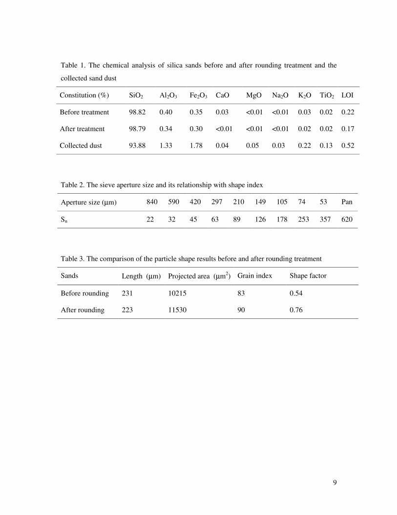
(3) The rounding treatment can purify the surface of the sand particles. The chemical analysis
of the sand particles and the collected dust from rounding equipment, as shown in Table
1, indicated that the content of Al2O3 and Fe2O3 in the dust was much higher than those in
sand particles. The purified sand surface could improve the adhesive strength between
resin and sand grain surface [2].
4.3 The shape analysis of the sand particles
The SEM observation of the sand particles before and after rounding treatment is shown in
Fig. 7, which revealed that the shape of sand particles after rounding treatment was improved.
The sharp-pointed particles were blunted. This would increase the bonding areas among sand
particles and hence increase the bonding strength.
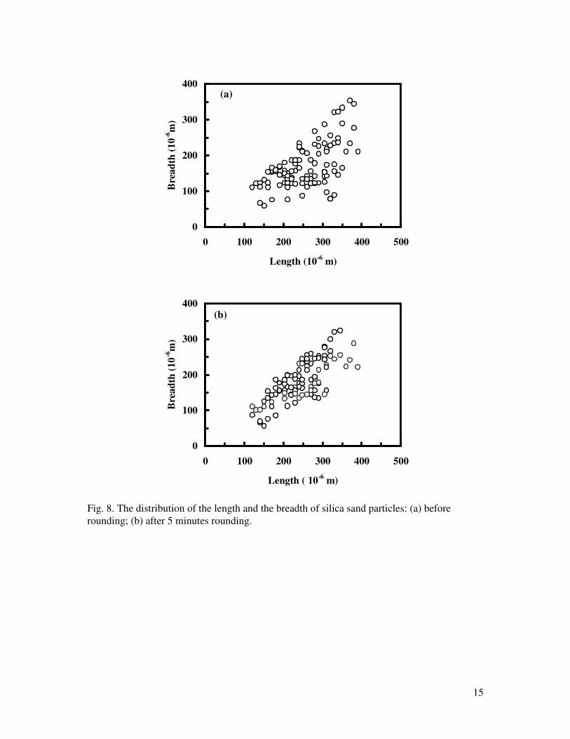
The measured length and breadth of the sand particles is shown in Fig. 8, which revealed the
length and breadth of the sand particles did not change significantly after the rounding
Page 7
7
treatment. Compared with the increase of the strength of rounded sands, the reduction of sand
particle distribution was very small.
As it is well known, the length and breadth could not exactly describe the shape of the sand
particles. As shown in Fig. 9, three kind of particles have the same length (L1=L2=L3).
Although they may stay on the same aperture sieve, they are totally different in shape. Of
them, two have the same projected area (A2=A3). But the perimeters are different
(P1<P2<P3). Therefore, it is difficult to distinguish them by either length or the projected
area or the perimeter.
In order to describe the sand particle shape more precisely, the combination of the length, the
projected area and the perimeter is necessary. In this study, the grain index and the roundness
coefficient were adopted. The grain index, F, is defined as F=Σ(Nn⋅Sn)/ΣNn, where Nn is the
number of the sand particles retained on the different sieves and Sn is the coefficient. The
relationship between aperture size of the sieve and the coefficient is shown in Table 2. The
shape factor, ξ, is defined as ξ=Ap⋅4π/P2, where Ap is the projected area and P is the perimeter
of the sand particle. Fig. 9 shows the relationship between the projected area and the shape
factor of the sand particles, which illustrates that the shape factor of the sand particles after
rounding treatment is larger than those before rounding treatment, even though the projected
area don’t change after rounding treatment. This means that the roundness of sand particles
after rounding treatment is improved. The experimental and theoretic results for the sand
grain index are summarised in Table 3. The grain index of the sand particles before and after
rounding was 83 and 90 respectively. The sand particle shape factor before and after rounding
was 0.54 and 0.76 respectively, which reveals that the rounding treatment could effectively
improve the shape of the sand particles.
5. Conclusion
The shape of foundry sands can be artificially improved without apparent breakage in
developed equipment. The combination of attrition energy, small-angle impact energy, small
compression energy and small shear energy is an effective approach for rounding foundry
sands. The developed foundry sand rounding equipment characterised by two horizontally
positioned eccentric cylinders can reduce the angular coefficient of silica sand from 1.49 to
Page 8
8
1.26 and increase the tensile strength of the resin-bonded specimen by 20-40%. The sieving
analysis and image analysis showed that the roundness of the sand particles could be
effectively improved without apparent breakage.
Page 9
9
Table 1. The chemical analysis of silica sands before and after rounding treatment and the
collected sand dust
Constitution (%) SiO2 Al2O3 Fe2O3 CaO MgO Na2O K2O TiO2 LOI
Before treatment 98.82 0.40 0.35 0.03 <0.01 <0.01 0.03 0.02 0.22
After treatment 98.79 0.34 0.30 <0.01 <0.01 <0.01 0.02 0.02 0.17
Collected dust 93.88 1.33 1.78 0.04 0.05 0.03 0.22 0.13 0.52
Table 2. The sieve aperture size and its relationship with shape index
Aperture size (µm) 840 590 420 297 210 149 105 74 53 Pan
Sn 22 32 45 63 89 126 178 253 357 620
Table 3. The comparison of the particle shape results before and after rounding treatment
Sands Length (µm) Projected area (µm2) Grain index Shape factor
Before rounding 231 10215 83 0.54
After rounding 223 11530 90 0.76
Page 10
10
1-feeder, 2-outer cylinder, 3-rotating rail, 4-transmission device, 5-inner rotor, 6-ventilating and discharge device, 7-motor, 8-frame, 9-shaft
Fig. 1. Schematic illustration of the developed equipment improving the roundness of the foundry sands.
Fig. 2. Schematic diagram of motion sand particle between outer cylinder and inner rotor.
Page 11
11
1.2
1.3
1.4
1.5
0 100 200 300Time (s)
Ang
ular
ity c
oeff
icie
nt
Fig. 3. The effect of rounding treatment time on the angularity coefficient of silica sands.
0
5
10
15
20
25
30
35
40
6 20 40 70 140 270Sieve number
Ret
aine
d on
siev
e (%
)
After rounding
Before rounding
(a)
Page 12
12
0
5
10
15
20
25
30
35
40
6 20 40 70 140 270Sieve number
Ret
aine
d on
siev
e (%
)
Before rounding
After rounding
0
5
10
15
20
25
30
35
40
6 20 40 70 140 270Sieve number
Ret
aine
d on
siev
e (%
)
Before roundingAfter rounding
Fig. 4. Sieve analysis of the different sands before and after 5 minutes rounding treatment (a) silica sands; (b) chromate sands; (c) olivine sands.
(b)
(c)
Page 13
13
0
0.5
1
1.5
2
2.5
0.5 1 1.5 2 2.5Resin addition (%)
Ten
sile
stre
ngth
(MPa
)Before roundingAfter rounding
Fig. 5. The effect of resin addition (based on sand) on the tensile strength of the furan resin bonded silica sands.
1.5
1.53
1.56
1.59
1.62
1.65
1.25 1.3 1.35 1.4 1.45 1.5 1.55Angularity coefficient
Vol
ume
dens
ity (g
/cm
3 )
Fig. 6. The volume density after packing of silica sands as a function of the angularity coefficient.
Page 14
14
Fig. 7. SEM photographs of the silica sand particles (a) before rounding; (b) after 5 minutes rounding.
(a)
1mm
(b)
1mm
Page 15
15
0
100
200
300
400
0 100 200 300 400 500
Length (10-6 m)
Bre
adth
(10-6
m)
0
100
200
300
400
0 100 200 300 400 500
Length ( 10-6 m)
Bre
adth
(10-6
m)
Fig. 8. The distribution of the length and the breadth of silica sand particles: (a) before rounding; (b) after 5 minutes rounding.
(a)
(b)
Page 16
16
L1, L2, L3: the maximum length of sand particles, respectively. A1, A2, A3: the projecting area of sand particles, respectively. P1, P2, P3: the periphery length of sand particles, respectively.
Fig. 9. Schematic illustration of the typical sand particle shapes
Page 17
17
0
0.5
1
1.5
2
2.5
0 0.2 0.4 0.6 0.8 1
Shape factor
Proj
ecte
d ar
ea (1
0-8m
2 )
0
0.5
1
1.5
2
2.5
0 0.2 0.4 0.6 0.8 1
Shape factor
Proj
ecte
d ar
ea (1
0-8m
2 )
Fig. 10. The relationship between the shape factor and the projected area of the silica sand particles: (a) before rounding treatment; (b) after 5 minutes rounding treatment.
(a)
(b)
Page 18
18
References
[1] American Foundrymen’s Society, Inc., Mould and core test handbook (American
Foundrymen’s Society Inc. Des Plaines, 2nd, 1989).
[2] C. A. Sanders, “Why sands control,” Foundry Trade Journal, 1954, AF10, 165-168.
[3] T. E. Garnar, Jr., “ Mineralogy of foundry sands and its effect on performance and
properties,” AFS Transactions, 1977, 90, 399-416.
[4] V. L. Weddinton, C. E. Mobeley, “Influence of sand surface chemistry on bonding”, AFS
Transaction, 1991, 99, 825-870.
[5] M. J.Ziegler, “Foundry sand Basics”, Foundry M&T, 1994, 122, 25-29.
[6] K. E. L . Nicholas, “The CO2-Silicate Process in Foundries”, BCIRA, 1972, 211.
[7] Z. Yu, “The morphology of foundry base sands”, Moulding Materials, 1985, 3, 25-30.
[8] Y. Gakwa, The Improvement treatment and its results of Silica Sand used for Chemical
Binder System, Immono. 1989, 59(10), 28-34.
[9] S. N. Ramrattan, P. J. Guichelaar, A. Palukuku and R. Tieder, “Study of foundry granular
media and its attrition”, AFS Transaction, 1996,104, 877-886.
[10] M. Coriolis, H. Lauth, Attrition calculation principle (Y. Wang, Mechanical Industry
Press, 1982, translated to Chinese).
[11] C. L. Pasher, Crushing and Grinding Process Handbook (John Wiley & Sons Limited,
1987), pp50-58, pp100-110, pp181-190.