606 MIXVENT-TD SYSTEM In-Line duct fans In-Line mixed flow duct fans MIXVENT System – COMBINATIONS The MIXVENT System includes a specific range of accessories enabling the installation of diffe- rent combinations of the MIXVENT –TD main- taining the concept that makes the difference: deliver the maximum airflow using the mi- nimum space. MIXVENT-TDx2 and MIXVENT-TDx3 To increase the pressure MIXVENT-TWIN To double the airflow MIXVENT-TWINx2 To increase the pressure and double the airflow
Transcript
606
MIX
VE
NT-
TD
SY
ST
EM
In-L
ine
duc
t fa
ns
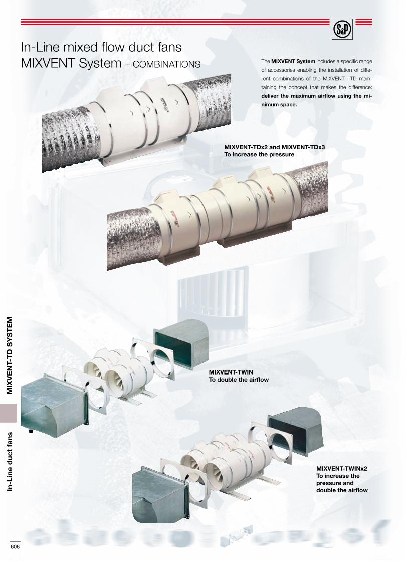
In-Line mixed flow duct fans MIXVENT System – COMBINATIONS The MIXVENT System includes a specific range
of accessories enabling the installation of diffe-
rent combinations of the MIXVENT –TD main-
taining the concept that makes the difference:
deliver the maximum airflow using the mi-
nimum space.
MIXVENT-TDx2 and MIXVENT-TDx3To increase the pressure
MIXVENT-TWINTo double the airflow
MIXVENT-TWINx2To increase thepressure anddouble the airflow
607
MIX
VE
NT-
TD
SY
ST
EM
In-L
ine
duc
t fa
ns
The MIXVENT-TDx2 range consists of two MIXVENT-
TD fans mounted in series to produce almost twice
the pressure of the single TD fan. System specially
recommended when the fan has the suitable airflow
and when an increase of the pressure is required
due to the high pressure drops.
MIXVENT-TDx2 are standard catalogue products,
from 350 to 1300 model. A TDx2 can also be ob-
tained coupling 2 TD model fans using a flange
MBR (see the accessories section).
Speed
(r.p.m.)
Maximum absorbed
power(W)
Maximum absorbed current
(A)
Airflow at free
discharge (m3/h)
Maximum operating
temperature (°C)
Sound pressure
level* (dB(A))
Weight
(kg)
TD-800/200 EX2250 1900
60 44
0,26 0,20
395 320
40 40
36 31
5,4
TDx2-500/150
1602500 1950
100 88
0,44 0,38
580 475
60 60
48 41
5
TDx2-800/200N2780 2480
140 120
0,60 0,52
880 690
60 60
48 44
8,7
TDx2-800/200 2500 2000
240 200
1,00 0,90
1020 790
60 60
52 48
8,7
TDx2-1000/2502800 2610
250 170
1,00 0,70
1020 900
60 60
57 51
18,7
TDx2-1300/2502520 2000
360 280
1,60 1,20
1320 980
60 60
57 52
18,7
* Sound pressure level radiated at 3 m at free air conditions with rigid ducts at the inlet and at the outlet.
Technical characteristics
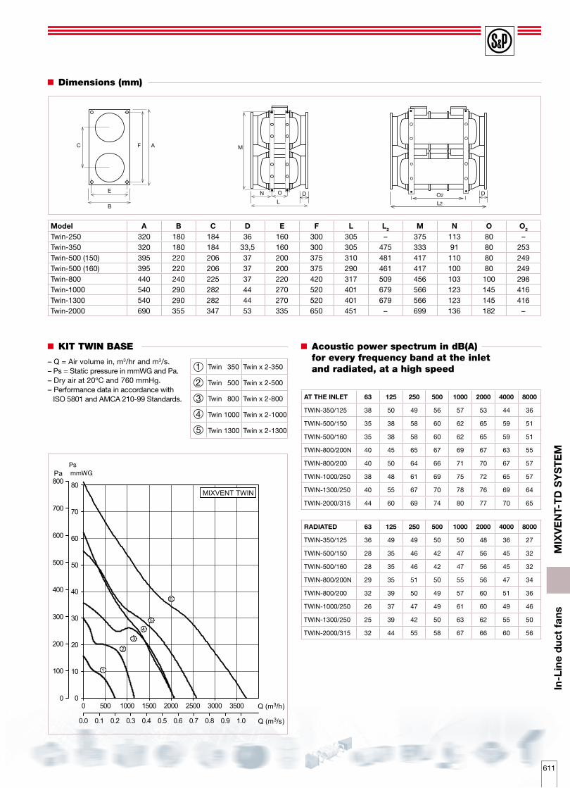
Dimensions (mm)
Acoustic power spectrum in dB(A) for every frequency band at the inlet andradiated, at a high speed.
– Q = Air volume in, m3/hr and m3/s. – Ps = Static pressure in mmWG and Pa.– Dry air at 20ºC and 760 mmHg.– Performance data in accordance with ISO 5801 and AMCA 210-99 Standards.
Performance curves
HS = High speedLS = Low speed
Ps PsmmWG mmWG
Ps PsmmWG mmWG
Ps PsmmWG mmWG
LSLS
HS HS
LS
LS
LS
LS
HS
HSHS
HS
609
MIX
VE
NT-
TD
SY
ST
EM
In-L
ine
duc
t fa
ns
– Q = Air volume in, m3/hr and m3/s.– Ps = Static pressure in mmWG and Pa.– Dry air at 20ºC and 760 mmHg.– Performance data in accordance with
ISO 5801 and AMCA 210-99 Standards.
MBR flange
MIXVENT-TDx3 design
Performance curves
Performance curves
A B C
A B C
G2
A
L G1
The MIXVENT-TDx3 range consists of a MIXVENT-
TDx2 and MIXVENT-TD fans mounted in series
using the flange MBR.
System specially recommended when the fan
has the suitable airflow and when an important
increase of the pressure is required due to the
very high pressure drop.
Technically more units could be installed in series
to increase the pressure but it is recommended
to carry out a study before.
MIXVENT-TDx3 Composition
TDx3-350/125 TD-350/125+TDx2-350/125+MBR-350
TDx3-500/150 TD-500/150+TDx2-500/150+MBR-500/150
TDx3-500/160 TD-500/160+TDx2-500/160+MBR-500/160
TDx3-800/200 TD-800/200+TDx2-800/200+MBR-800
TDx3-1000/250 TD-1000/250+TDx2-1000/250+MBR-1000
TDx3-1300/250 TD-1300/250+TDx2-1300/250+MBR-1000
MIXVENT-TDx3 A G1 G2 L
TD x 3-350/125 755 80 253 213
TD x 3-500/150 766 80 249 223
TD x 3-500/160 726 80 249 203
TD x 3-800/200 801 100 298 207
TD x 3-1000/250 1055 145 416 246
TD x 3-1300/250 1055 145 416 246
TD x 3-350
TD x 3-500
TD x 3-800
TD x 3-1000
TD x 3-1300
MBR flange
MBR flangeA and B or A and C must operate
Airflowdirection
Airflowdirection
1
2
3
4
5
PsmmWG
610
MIX
VE
NT-
TD
SY
ST
EM
In-L
ine
duc
t fa
ns
The MIXVENT-Twin consists of two MIXVENTTD
fans mounted in parallel using the Kit Twin Base
(suitable from 250 to 2000 model).
System specially recommended when a large
airflow is required (at the same pressure) within
a confined space, or where a supplementary air-
flow is occasionally needed.
Once mounted, the whole assembly is ready to
be connected to a rectangular duct using the
two rectangular flanges supplied with the Kit
Twin Base.
The independent operation of two MIXVENT-TD
requires the use of back draft shutters at the dis-
charge (outlet) in order to prevent the air recy-
cling through the stationary fan.
It is also needed in installations where it is neces-
sary to mount at the same place, two fans with
the same characteristics, for extraction and sup-
ply operations.
MIXVENT-TWIN system with backdraft shutter fitted
Accessories to mount MIXVENT-TWIN system
KIT TWIN BASE
Kit Twin Base-250 + 2 TD -160/100
Kit Twin Base-250 + 2 TD 250/100
Kit Twin Base-350 + 2 TD -350/125
Kit Twin Base-500/150 + 2 TD-500/150
Kit Twin Base-500/160 + 2 TD-500/160
Kit Twin Base-800 + 2 TD-800/200
Kit Twin Base-1000 + 2 TD-1000/250
Kit Twin Base-1000 + 2 TD-1300/250
Kit Twin Base-2000 + 2 TD-2000/315
This accessory consists of two rectangular duct couplings with standardized dimensions and two supports allowing mounting two TD or two TDx2 fans in parallel.
The independent operation of two MIXVENT-TD requires the use of back
draft shutters at the discharge (outlet) in order to prevent the air recycling
through the stationary fan.
KIT TWIN BASE Dimensions (mm)L H
Nominal dimensions of the rectangular duct (mm)L H
KIT TWIN BASE 250 320 180 280 140
KIT TWIN BASE 350 320 180 280 140
KIT TWIN BASE 500/150 395 220 355 180
KIT TWIN BASE 500/160 395 220 355 180
KIT TWIN BASE 800 440 240 400 200
KIT TWIN BASE 1000 540 290 500 250
KIT TWIN BASE 2000 690 355 630 315
B
H
MIXVENT-TWIN
MIXVENT-TWIN system
611
MIX
VE
NT-
TD
SY
ST
EM
In-L
ine
duc
t fa
ns
KIT TWIN BASE Acoustic power spectrum in dB(A) for every frequency band at the inletand radiated, at a high speed
the discharge (outlet) in order to prevent the air
recycling through the stationary fan.
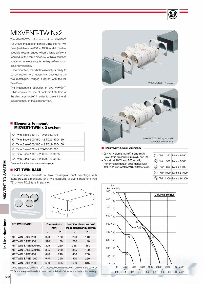
MIXVENT-TWINx2 system
MIXVENT-TWINx2 system with backdraft shutter fitted
Elements to mount MIXVENT-TWIN x 2 system
KIT TWIN BASE
Kit Twin Base-350 + 2 TDx2-350/125
Kit Twin Base-500/150 + 2 TDx2-500/150
Kit Twin Base-500/160 + 2 TDx2-500/160
Kit Twin Base-800 + 2 TDx2-800/200
Kit Twin Base-1000 + 2 TDx2-1000/250
Kit Twin Base-1000 + 2 TDx2-1300/250
Due to the isolated operation of TD models, backdraft shutters mounted at the outlet of
TD fans are required in order to avoid the backdraft of air when the fan is not operating.
KIT TWIN BASE Dimensions (mm)
L H
Nominal dimensions of the rectangular duct (mm)
L H
KIT TWIN BASE 250 320 180 280 140
KIT TWIN BASE 350 320 180 280 140
KIT TWIN BASE 500/150 395 220 355 180
KIT TWIN BASE 500/160 395 220 355 180
KIT TWIN BASE 800 440 240 400 200
KIT TWIN BASE 1000 540 290 500 250
KIT TWIN BASE 2000 690 355 630 315
B
H
MIXVENT-TWINx2
Performance curves
This accessory consists of two rectangular duct couplings with standardized dimensions and two supports allowing mounting two TD or two TDx2 fans in parallel.
Backdraft shutter, see accessories page.
Twin 350 Twin x 2-350
Twin 500 Twin x 2-500
Twin 800 Twin x 2-800
Twin 1000 Twin x 2-1000
Twin 1300 Twin x 2-1300
1
2
3
4
5
– Q = Air volume in, m3/hr and m3/s. – Ps = Static pressure in mmWG and Pa.– Dry air at 20ºC and 760 mmHg.– Performance data in accordance with