Page 1
In Search of the “Absolute” Optical Phase
Xiaoqin (Elaine) Li
Ryan Smith
Jessica Pipis
Steve Cundiff
Rich Mirin
Tara Fortier
David Jones
Ravi Bhat John Sipe
JILA, NIST, CU (Boulder) U of T (Toronto)
Pete Roos (JILA, NIST, CU)
Page 2
OutlineImportant concepts and motivation
• How fast is ultrafast?• The “Absolute” optical phase.• Why do we care?
Creation and control of ultrashort pulses
• Modelocking.• “Absolute” phase evolution – time vs. frequency.• Detection methods.
Quantum interference control (QIC) in semiconductors
• Background.• Concepts and theory.• Experimental studies and stabilization using QIC.
Page 3
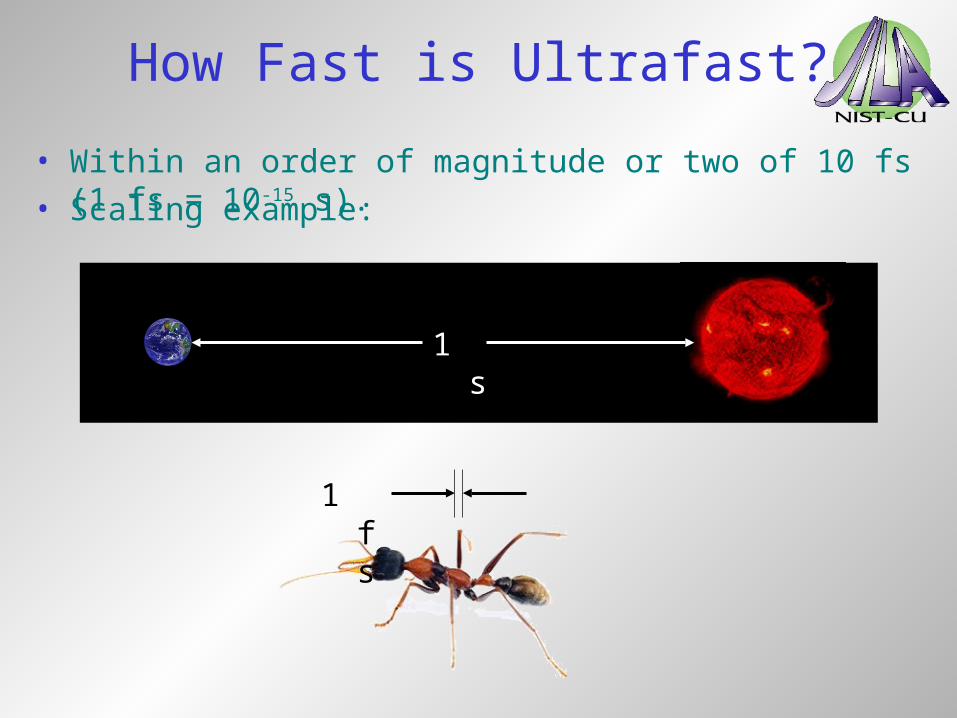
How Fast is Ultrafast?
• Within an order of magnitude or two of 10 fs (1 fs = 10-15 s).
1 s
1 fs
• Scaling example:
Page 4
“Absolute” Optical Phase
Carrier
Envelope
• Pulse envelope provides “absolute” phase reference.
Carrier-envelope
(CE) phase
• Ultrafast optics approaching interesting regime:
Optical carrier cycle (~ 3fs)
Pulse Duration
(~10 fs)
Page 5
Why do we care?
• Not only control of intensity envelope … field.• Optical waveform synthesis. • AWG at optical frequencies.
2. Ultimate control of light.
• Extreme nonlinear optics.• Photoionization and x-ray generation.• Photoelectron emission from metal surfaces.• Coherent control experiments.
1. Can affect light-matter interactions.
3. Precision measurements.• Optical frequency metrology.
• Linear / nonlinear spectroscopy.
Page 6
OutlineImportant concepts and motivation
• How fast is ultrafast?• The “Absolute” optical phase.• Why do we care?
Creation and control of ultrashort pulses
• Modelocking.• “Absolute” phase evolution – time vs. frequency.• Detection methods.
Quantum interference control (QIC) in semiconductors
• Background.• Concepts and theory.• Experimental studies and stabilization using QIC.
Page 7
Short Laser Pulses
External switch:
Gain
Mirrors
Output
beam
Switch
Pulses
Internal switch:
Gain
Mirrors
Switch
Pulses
Page 8
Ultrashort Laser Pulses
• Requires phase locked modes.
Modelocking:
Frequency
Intensity
Time
Intensity 30 modes
random phases
30 modes
all in phase
• Coherent interference effect.
Page 9
OutputCoupler
HighReflector
LaserCavity Free Space
CE Phase Instability
• In laser cavity: vgroup≠ vphase• CE phase evolves from pulse to pulse outside cavity.
Page 10
Random Evolution
• Uncontrolled CE phase evolution:
• Limits meaningful physics and applications.
Page 11
No Evolution
• Fixed CE phase:
• Enables meaningful physics and applications.
Page 12
Controlled Evolution
• Controlled CE phase evolution:
• Also enables meaningful physics and applications.
Page 13
cece
Time vs. Frequency Domain
I()
0
Frequency Domain
Time Domain
t
E(t)
F.T. ce
ce
ce
ce
ce
ce
ce
ce
x2ce c
e
ce
ce
frep
p
p
Page 14
Time vs. Frequency Domain
Time Domain
t
E(t)
0
Frequency Domain
I()
F.T.
x2+f0 +f0
+f0
f0
f0=frep
Page 15
Some Detection Methods
Second harmonic generation (-to-2)Telle et al., Appl. Phys. B (1999);Jones et al., Science 288, 635 (2000);Apolonski et al., PRL 85, 740 (2000)
Rabi sideband interferenceVu et al., PRL 92, 217403 (2004);Mücke et al., Opt. Lett. 29 2160 (2004)
Photoionization of gasesDurfee et al., PRL 83 2187 (1999);Paulus et al., Science 414, 182 (2002)
Photoelectron emission from metalsLemell et al., PRL 90, 076403 (2003);Apolonski et al., PRL 92, 073902 (2004)
semiconductor
Rabi
metal
vapor
Page 16
OutlineImportant concepts and motivation
• How fast is ultrafast?• The “Absolute” optical phase.• Why do we care?
Creation and control of ultrashort pulses
• Modelocking.• “Absolute” phase evolution – time vs. frequency.• Detection methods.
Quantum interference control (QIC) in semiconductors
• Background.• Concepts and theory.• Experimental studies and stabilization using QIC.
Page 17
Quantum Interference
~sinabcd
a
b
c
d
~sin
• Two distinct quantum mechanical pathways.
• Connect same initial and final states.
State populationShapiro et al, J Chem Phys 84, 4103 (1986)
Atomic photoionizationYin et al, PRL 69, 2353 (1992)
Molecular photodissociationSheehy et al, PRL 74, 4799 (1995)
Semiconductor spin currentsBhat et al, PRL 85, 5432 (2000)
Semiconductor charge currentsHaché et al, PRL 78, 306 (1997)
Relative optical phase can coherently control:
Page 18
E
ConductionBand
ValenceBand
k
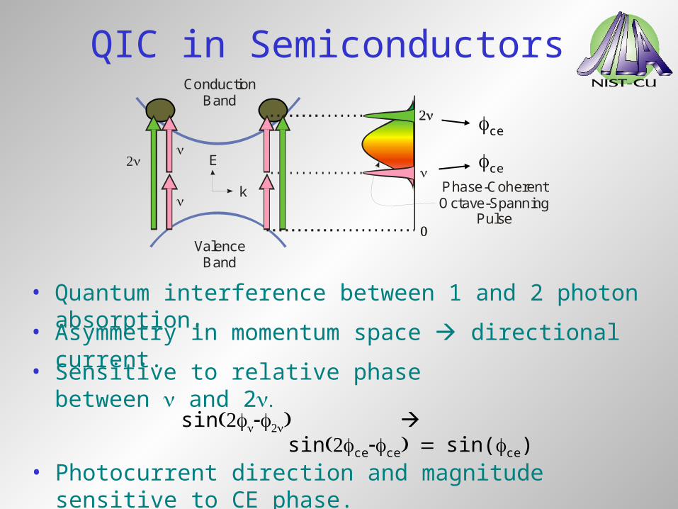
QIC in Semiconductors
• Quantum interference between 1 and 2 photon absorption.
Phase-CoherentOctave-Spanning
Pulse
• Sensitive to relative phase between and 2
• Asymmetry in momentum space directional current.
sin
• Photocurrent direction and magnitude sensitive to CE phase.
sincecesin(ce)
ce
ce
Page 19
QIC in Semiconductors
k
)k(veJ
{ 22 )k(a)k(a
}
Atanasov et al., PRL 76, 1703 (1996); Haché et al., PRL 78, 306 (1997)
Velocity
Charge TransitionAmplitudes
One-photon Two-photon
From Fermi’s Golden Rule:
Page 20
QIC in Semiconductors
k
)k(veJ
{ ][ c.c.)k(a)k(a2
}2
2 )k(a
2
)k(a
One-photonabsorption
Two-photonabsorption
Atanasov et al., PRL 76, 1703 (1996); Haché et al., PRL 78, 306 (1997)
Velocity
Charge TransitionAmplitudes
QuantumInterference
E
ConductionBand
ValenceBand
k
Page 21
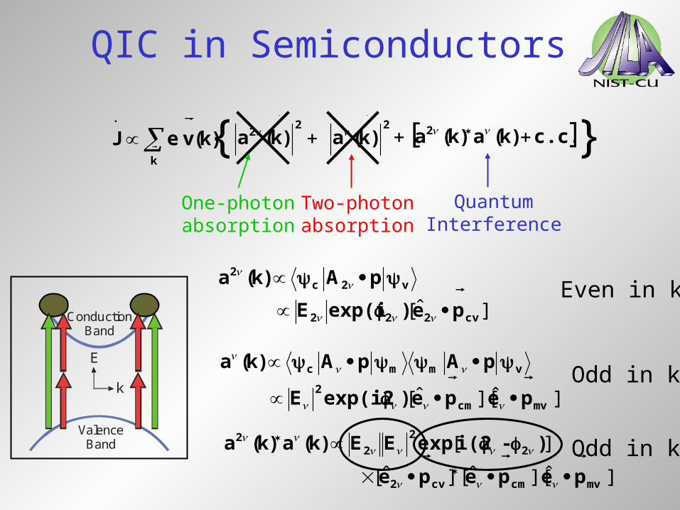
QIC in Semiconductors
k
)k(veJ
{ ][ c.c.)k(a)k(a2
}2
2 )k(a
2
)k(a
][ cv222
v2c2
pe)exp(iE
pA)k(a
ˆ
One-photonabsorption
Two-photonabsorption
QuantumInterference
E
ConductionBand
ValenceBand
k
Even in k
Page 22
QIC in Semiconductors
k
)k(veJ
{ ][ c.c.)k(a)k(a2
}2
2 )k(a
2
)k(a
]][[ mvcm
2
vmmc
pepe)exp(i2E
pApA)k(a
ˆˆ
][ cv222
v2c2
pe)exp(iE
pA)k(a
ˆ
One-photonabsorption
Two-photonabsorption
QuantumInterference
E
ConductionBand
ValenceBand
k
Even in k
Odd in k
Page 23
QIC in Semiconductors
]][[][
][
mvcmcv2
2
2
22
pepepe
)-i(2expEE)k(a)k(a
ˆˆˆ
k
)k(veJ
{ ][ c.c.)k(a)k(a2
}2
2 )k(a
2
)k(a
]][[ mvcm
2
vmmc
pepe)exp(i2E
pApA)k(a
ˆˆ
][ cv222
v2c2
pe)exp(iE
pA)k(a
ˆ
One-photonabsorption
Two-photonabsorption
QuantumInterference
E
ConductionBand
ValenceBand
k
Even in k
Odd in k
Odd in k
Page 24
Simplified Setup
Stabilized Ti:sapphire modelocked laser
Splitmirror
Time delay adjustFiberbroadening
Lock-in amplifier
I/V
Lens
Sample
RF spectrumanalyzer
Prism
Prism
~15 fs, 93 MHz rep. rate, up to 400 mW avg. power
LT-GaAs
Page 25
Signal Amplitude
2.2k 2.4k 2.6k
-40
-20
0
10 Hz Res. BW
Signal Background
(b)
RF
Po
we
r (d
B)
Signal Frequency (Hz)
Current ≈ 100 pA
• Now have >500 pA.
Page 26
Incident Power
• < J > ~ I(I2)1/2
0.0 2.0 4.0 6.0 8.00.0
0.1
0.2
0.3
0.4
0.0 0.2 0.4 0.6 0.8
QIC
Sig
na
l (m
Vrm
s)
Infrared Power (mW)
Theory
2 data
data
Visible Power (mW)
Roos et al., JOSA B (to be published)
Page 27
CE Phase Sensitivity
25 50 75 100
0.0
0.5
1.0
1.5
Signal Theory
(a) o
o
o
o
40
35
3025
o20o15
Ph
ase
(-
rad
)
Time (s)
• Verification that phase of QIC signal varies with shifts in carrier-envelope phase.
Fortier et al., PRL 92, 147403 (2004)
Page 28
Detection Bandwidth
• With transimpedance amplifier: 830 kHz.
103 104 105 106 107-20
-10
0
10
CST
=0.2 pf
CST
=0 pf
VoltageAmplification
TransimpedanceAmplification
Rel
ativ
e S
igna
l Pow
er (
dB)
Stabilization Frequency (Hz)
Roos et al., JOSA B (to be published)
Page 29
Simplified Stabilization Setup
Output coupler
High reflectorPump
Ti:sapphire crystal
Prism
Prism
Splitmirror
Time delay adjustFiberbroadening
Stabilizationelectronics
I/V
LensSample
To phase noiseanalysis
Ti:sapphire laser
~
Mixer
Synthesizer
Page 30
Stabilization via QIC
• CE phase evolution stabilized.
10-1 100 101 102 103 10410-10
10-5
100
105
1010
Locked
UnlockedP
ha
se N
ois
e P
SD
(ra
d2 /Hz)
Frequency (Hz)
Roos et al., Opt. Lett. (to be published)
Page 31
Summary
• “Absolute” (carrier-envelope) phase: phase difference between carrier peak and envelope peak.
• Important for light-matter interactions, optical waveform synthesis, precision measurements.
• Modelocked lasers enable access to “absolute” phase.
• To detect: compare phase of spectral components in frequency domain through nonlinear process.
• Quantum interference control (QIC) in semiconductors gives phase-sensitive photocurrent.
• “Absolute” phase stabilization using QIC.