LDS 6, typical installation with transmitted-light sensors
LDS 6 is a diode laser gas analyzer with a measuring principle based on the specific light absorption of different gas compo-nents. LDS 6 is suitable for fast and non-contact measurement of gas concentrations in process or flue gases. One or two sig-nals from up to three measuring points are processed simultane-ously by the central analyzer unit. The in-situ cross-duct sensors at each measuring point can be separated up to 700 m from the central unit by using fiber-optic cables. The sensors are de-signed for operation under harsh environmental conditions and contain a minimum of electrical components.
■ Benefits
The in-situ gas analyzer LDS 6 is characterized by a high avail-ability and unique analytical selectivity, and is optimally suitable for numerous applications. LDS 6 enables the measurement of one or two gas components or - if desired - the gas temperature directly in the process:• With high dust load• In hot, humid, corrosive, explosive, or toxic gases • In applications showing strong varying gas compositions • Under harsh environmental conditions at the measuring point• Highly selective, i.e. mostly without cross-sensitivities
LDS 6 properties:• Little installation effort• Minimum maintenance requirements• Extremely rugged design• High long-term stability through built-in, maintenance-free
reference gas cell, field calibration is unnecessary• Real-time measurements
Moreover, the instrument provides warning and failure mes-sages upon:• Need for maintenance
- Erroneous reference function- Bad signal quality
• Violation of a lower or upper alarm level for the measured variable
• Transmitted amount of light violating an upper or lower limit
■ Application
Applications• Process optimization• Continuous emission monitoring for all kinds of fuels (oil, gas,
coal, and others) • Process measurements in power utilities and any kind of incin-
erator• Process control• Explosion protection• Measurements in corrosive and toxic gases• Quality control• Environmental protection• Plant and operator safety
Sectors• Power plants• Steel works• Cement industry• Chemical and petrochemical plants• Automotive industry• Waste incinerators• Glass and ceramics production• Research and development• Semiconductor and computer chip production
Special applications
In addition to the standard applications, special applications are available upon request. These contain both an expansion of the temperature and pressure range, as well as an expansion of the concentration measuring range. Furthermore, other gas species can be measured using special application.
The gas analyzer LDS 6 consists of a central unit and up to three in-situ sensors. The connection between the central unit and the sensors is established by a so-called hybrid cable, which con-tains optical fibers and copper wires. An additional cable con-nects the transmitter and receiver parts of the cross-duct sensor.
Central unit
The central unit is housed in a 19" rack unit housing with 4 fixing points for mounting• in a hinged frame• in racks with or without telescopic rails
Display and operator panel• Large LCD field for simultaneous display of measurement
result and device status• Contrast of the LCD field is adjustable via the menu• LED background illumination of the display with energy-
saving function• Easy-to-clean membrane touch pad with softkeys• Menu-driven operation for parameterization and diagnostics• Operation support in plain text
Inputs and outputs• One to three measurement channels with hybrid connections
for the sensors at the measuring points• 2 analog inputs per channel for process gas temperature and
pressure• 2 analog outputs per channel for gas concentration(s). For
selected versions, the transmission can be read out as an alternative.
• 6 freely configurable digital inputs per channel for signaling faults or maintenance requests from external temperature or pressure transducers or sensor purging failure.
• 6 freely configurable digital outputs per channel (signaling of fault, maintenance requirements, function control, trans-mission limit alarm, concentration limit alarm, store analog output)
Communication
Network connection: Ethernet (T-Base-10) for remote diagnos-tics and maintenance.
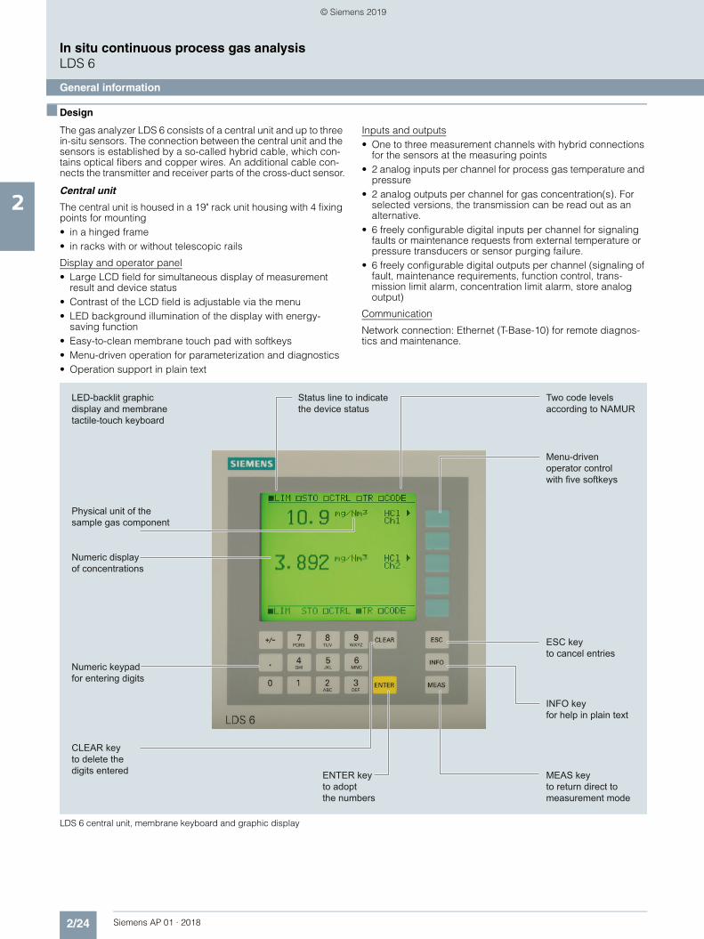
LDS 6 central unit, membrane keyboard and graphic display
Physical unit of the sample gas component
Status line to indicate the device status
LED-backlit graphicdisplay and membrane tactile-touch keyboard
• In-situ cross-duct sensors, configured as transmitter and detector unit, connected via sensor cable
• Connection to the LDS 6 central unit via a so-called hybrid cable of max. 700 m length (total hybrid and sensor connecting cable length: max. 250 m in Ex Zone 0 and Ex Zone 1)
• Stainless steel, some painted aluminum• IP65 degree of protection for sensor• Adjustable flanges with flange connection• DN 65/PN 6, ANSI 4"/150 lbs • Optional flameproof window flanges with dimensions: DN 65/
PN 6, DN 80/PN 16, ANSI 4"/150 lbs, other process interfaces available on request
• Purging facilities on the process and the sensor sides, config-urable application with purging gas connections for: - Instrument air- Purging air blower- Steam- Nitrogen- Process gases to which the pressure equipment directive
cat. 2 does not apply• In combination with high-pressure window flanges, purging
can be performed at the process end with instrument air or nitrogen
• Quick release fasteners for cleaning the measurement openings and the sensor window
• Optional: Version with explosion protection in accordance with ATEX / IEC Ex ia
• Sensor type CD 6 is compliant with the pressure equipment directive
Parts in contact with the process gas
The sensors normally do not come into contact with the process gas, since purging with a gaseous media is applied at the pro-cess side. Stainless steel purging gas tubes in front of the sensor windows are immersed slightly into the process gas and thus limit the purging volume. Special materials such as Hastelloy and plastics (PP) are available on request.
Hybrid and sensor cables
A combination of fiber-optic cables and twisted copper wires connects the sensors to the central unit. The hybrid cable con-nects the central unit with the detector unit of the sensor, the sen-sor cable connects the transmitter and receiver units of the sen-sor.
For installation in Ex-protected environments, the legislative reg-ulations have to be complied with, such as the spatial separation of intrinsically-safe from non-intrinsically-safe cables.
In compliance with standard EN IEC 60079-14, systems with in-trinsically-safe circuits must be installed such that their intrinsic safety is not impaired by electric or magnetic fields. Therefore the hybrid and sensor cables of the LDS 6 in an Ex application must be routed in such a way that they cannot generate electric or magnetic fields, e.g. by coiling them in more than one cable loop. To guarantee a good signal quality and to avoid impermis-sible inductance loops, the hybrid and sensor cables should be kept as short as possible.• The distance between central unit and measuring point can
be- up to 250 m for Ex units when used in Zone 0 and Zone 1
(total hybrid and sensor connecting cable length)- up to 700 m for Ex units used in Zone 2 and for non-Ex units
• Hybrid and sensor cables - Multimode fiber-optic cable, provided with SMA connections
for transmission of the measured signal- Two-wire copper cable, in twisted pair version, for +24 V
supply of the detector electronics (+12 V in the case of Ex-suitable instruments)
• Additionally for the hybrid cable: - Single-mode fiber-optic cable, configured double-sided with
E2000 connectors for transmission of laser light• Rugged cable sheath for laying in open cable ducts or
LDS 6 is a gas analyzer employing single-line molecular absorp-tion spectroscopy. A diode laser emits a beam of near-infrared light, which passes through the process gas and is detected by a receiver unit. The wavelength of the laser diode output is tuned to a gas-specific absorption line. The laser continuously scans this single absorption line with a very high spectral resolution.
The result is a fully resolved single molecular line which is ana-lyzed in terms of absorption strength and line shape. The influ-ence of cross-sensitivities on the measurement is negligible, since the quasi-monochromatic laser light is absorbed very se-lectively by only one specific molecular line in the scanned spectral range.
Basic design of the LDS 6
Configuration examples:
A feature of the in-situ analytical procedure is that the physical measurement takes place directly in the stream of process gas, and usually also directly in the actual process gas line. All pro-cess parameters such as gas matrix, pressure, temperature, moisture, dust load, flow velocity and mounting orientation can influence the measuring properties of the LDS 6 and must there-fore be systematically investigated for each new application.
A feature of the standard applications defined in the ordering data of the LDS 6 is that the typical process conditions are well-known, documented, and the guaranteed measuring properties can be proven by reference installations. If you cannot find your application among the standard applications, please contact Siemens. We will be pleased to check your possible individual application of the LDS 6. You can find an application question-naire on the LDS 6 product pages on the Internet: www.siemens.com/insituquestionnaire
Typical transmitted light setup of LDS 6, in-situ
To avoid contamination of sensor optics on the process side, clean gaseous purging media such as instrument air, N2 or steam are used. Purging air tubes on the sensor heads, which slightly penetrate into the process gas stream, define the effec-tive measuring path length.
P1
P0
PR
P2
P3
Measuredvolume
E/O
Channel 1Lasercontrol
Diodelaser
Optocoupler
Referencecell
CPU anddisplay
Signalprocessing
Laser lightElectrical signals
Reflected LED light
Central unit Hybrid cables Measurement path
E/O
E/O
E/O
Measuredvolume
Measuredvolume
Channel 2
Channel 3
E/O
E/O
Central unit
Hybrid cable
Supplementary channel (option)
Supplementary channel (option)
Transmitter unit Receiver
Process flange
Sensor connecting cable
Measurement path length
Gas concentrationFlue gas compositionSteamDust loadGas velocityGas temperatureGas pressure
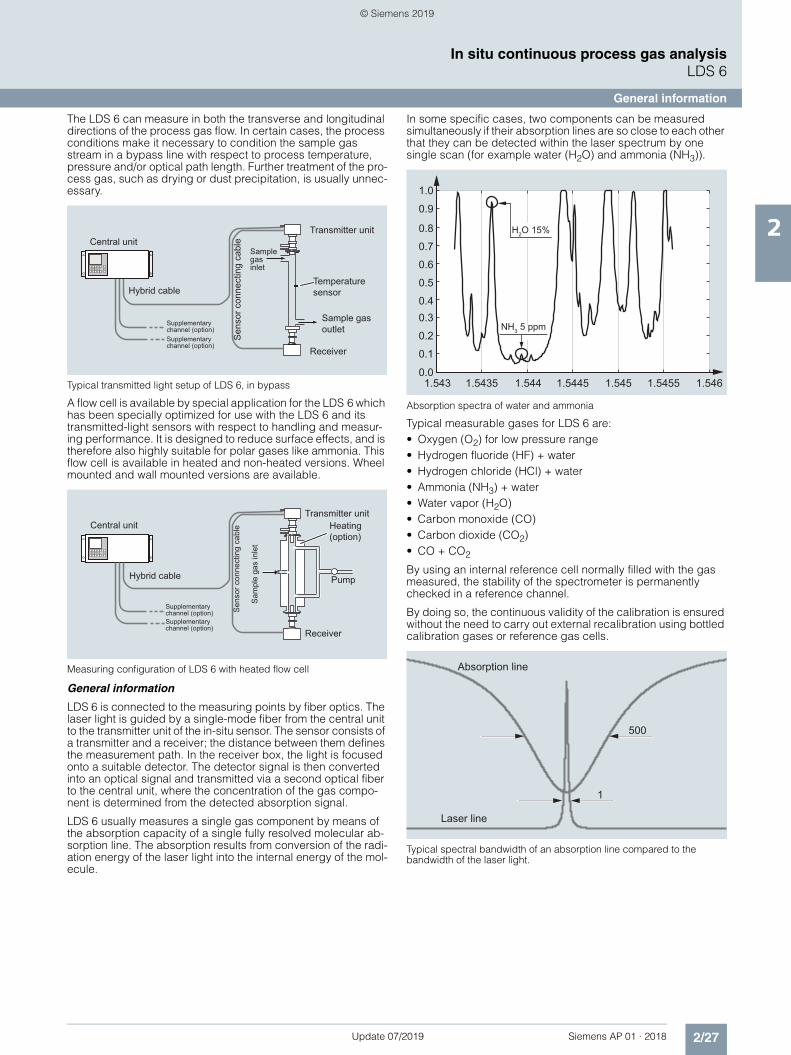
The LDS 6 can measure in both the transverse and longitudinal directions of the process gas flow. In certain cases, the process conditions make it necessary to condition the sample gas stream in a bypass line with respect to process temperature, pressure and/or optical path length. Further treatment of the pro-cess gas, such as drying or dust precipitation, is usually unnec-essary.
Typical transmitted light setup of LDS 6, in bypass
A flow cell is available by special application for the LDS 6 which has been specially optimized for use with the LDS 6 and its transmitted-light sensors with respect to handling and measur-ing performance. It is designed to reduce surface effects, and is therefore also highly suitable for polar gases like ammonia. This flow cell is available in heated and non-heated versions. Wheel mounted and wall mounted versions are available.
Measuring configuration of LDS 6 with heated flow cell
General information
LDS 6 is connected to the measuring points by fiber optics. The laser light is guided by a single-mode fiber from the central unit to the transmitter unit of the in-situ sensor. The sensor consists of a transmitter and a receiver; the distance between them defines the measurement path. In the receiver box, the light is focused onto a suitable detector. The detector signal is then converted into an optical signal and transmitted via a second optical fiber to the central unit, where the concentration of the gas compo-nent is determined from the detected absorption signal.
LDS 6 usually measures a single gas component by means of the absorption capacity of a single fully resolved molecular ab-sorption line. The absorption results from conversion of the radi-ation energy of the laser light into the internal energy of the mol-ecule.
In some specific cases, two components can be measured simultaneously if their absorption lines are so close to each other that they can be detected within the laser spectrum by one single scan (for example water (H2O) and ammonia (NH3)).
Absorption spectra of water and ammonia
Typical measurable gases for LDS 6 are:• Oxygen (O2) for low pressure range• Hydrogen fluoride (HF) + water• Hydrogen chloride (HCl) + water• Ammonia (NH3) + water• Water vapor (H2O)• Carbon monoxide (CO)• Carbon dioxide (CO2)• CO + CO2
By using an internal reference cell normally filled with the gas measured, the stability of the spectrometer is permanently checked in a reference channel.
By doing so, the continuous validity of the calibration is ensured without the need to carry out external recalibration using bottled calibration gases or reference gas cells.
Typical spectral bandwidth of an absorption line compared to the bandwidth of the laser light.
As long as the laser beam is able to generate a suitable detector signal, the dust load of the process gases does not influence the analytical result. By applying a dynamic background correction, measurements can be carried out without any negative impact. Under good conditions, particle densities up to 100 g/Nm3 (dis-tance 1 m) can be handled by the LDS 6. Varying dust loads are compensated by scanning the laser over the gas absorption line and the current background.The effect of a high dust load is complex and depends on the path length and particle size. The optical damping increases at longer path lengths. Smaller particles also have a very large in-fluence on the optical attenuation. With a combination of high dust load, long path length and small particle size, the technical support at Siemens should be consulted.
Temperature
The effect of temperature on the absorption strength of the mol-ecule line is compensated by a correction factor. A temperature signal can be fed into an analog instrument from an external temperature sensor. This signal is then used to correct the influ-ence of the temperature on the observed line strength. If the tem-perature of the sample gas remains constant, it is alternatively possible to carry out a static correction using a preset value.At high process gas temperatures, generally from approximately 1 000 °C, there may be noticeable broadband IR radiation of gas and dust, or flames may occasionally occur in the measurement path. An additional optical bandpass filter for an LDS 6 measur-ing O2 can be set upstream of the detector to protect it and pre-vent saturation by the strong background radiation.
Pressure
The effect of pressure on the absorption line, and consequently on the measured concentration, is compensated with a correc-tion factor. The gas pressure can affect the line shape of the mo-lecular absorption line. An analog pressure signal can be sent to the device from an external pressure sensor to fully compensate for the effect of the pressure including the density effect.
Optical path length
The absorption values analyzed by the LDS 6 are typically small. According to the Lambert-Beer law, the absorption of laser light depends on the optical path length within the gas, among other factors. Therefore, the precision in determining the effective op-tical path length in the process might limit the overall precision of the measurement.As the sensor optics on the process side normally need to be purged to keep them clean over a long period of time, the thick-ness of the mixing zone between the purging medium and the process gas and its concentration distribution need to be con-sidered. In a typical in-situ installation directly in the line and with some meters of path, the influence of the purging gas on the ef-fective path length can be neglected.Path length and dust load are mutually influencing: the higher the dust load in the process, the shorter the max. possible path length. For short path lengths in the range ≤ 0.3 m, contact Sie-mens Technical Support.
Maintenance and fault messages
LDS 6 outputs different warnings via relays:• Need for maintenance (measured value is not influenced)• Operating error (measured value might be influenced)
Note
Individual requirements for the measuring point can make the utilization of special sensor equipment necessary. The possibili-ties for adapting the sensors are:• Different purging media, such as instrument air, ambient air,
nitrogen or steam• Different purging modes on process and sensor sides• Special materials of purging tubes and/or sensor flanges• Cooling or heating of the sensors• Explosion-protected sensor configurations
Essential characteristics• Integrated calibration adjustment with an internal reference
cell• Negligible long-term drifts of zero and span• Dynamic background correction for varying dust loads• Isolated signal outputs, 4 to 20 mA • User-friendly, menu-driven operation• Selectable time constants (response time)• Two user levels with individual access codes for prevention of
unwanted and unauthorized operations• Operation according to NAMUR recommendations• Monitoring of overall optical transmission• Remote preventive maintenance and servicing via Ethernet/
modem• Straightforward replacement of the central unit, since connec-
tions can easily be removed• Sensor and central unit housing free of wear and corrosion• Easy operation with a numerical keypad and menu prompting
Certified versions for emission monitoring
The LDS 6 is available as certified instrument for emission mon-itoring of NH3, NH3/H2O, H2O, HCl, HCl/H2O. The certificates are issued by TÜV for Germany and MCERTS for the United Kingdom. Test kits for ammonia, water and HCl should be used to conduct regular calibration and linearity checks on site. These kits can be ordered separately as instrument accessories. For new analyzer orders, the NH3, NH3/H2O and H2O kits named "Version 2" must be ordered. For analyzers already installed, contact Siemens Technical Support. for spotting the correct kit version, or consult the instrument manual.
Assembly with certified, maintenance-free calibration gas cell with connections for laser fiber-optic conductors and detector module of cross-duct sensor. These are used to rapidly verify the factory calibration in the field without compressed gas bottles or flow cell.
Calibration test kits are available for the following sample gases:O2, NH3, CO, CO2, CO/CO2. A "Zero gas test kit" is also available for individual applications (see Additional units).
Example of an assembly for verification of calibration
1) The accuracy corresponds to intrinsic uncertainty according to IEC 61207 for 7MB6121-xKD00-0xxx.
Analytical performance
Measuring range Depending on sample gas compo-nent: See table for standard applica-tions.
Detection limit (DL):
Calculated in accordance with VDI 2449, measured on every sup-plied analyzer during the temperature test (between 5 ... 45 °C) in accor-dance with VDI 4203.
Depending on sample gas compo-nent: see table for standard applica-tions.
For application letter ET and FT: in accordance with the requirements of 17th and 27th BImSchV
Smallest recommended measuring range (with 1 m path length)
Depending on sample gas compo-nent: see table for standard applica-tions.
The maximum applicable measuring ranges can be found in the table of standard combinations. These can only be applied if the individual pro-cess conditions allow it. Please con-tact the Technical Support from Siemens for checking the applicabil-ity.
Accuracy1) 2% / 5%, depending on sample gas component and application letter. At best: detection limit. See table for standard applications.
For application letter ET and FT: in accordance with the requirements of 17th and 27th BImSchV
Linearity Better than 1%
Repeatability 2% of the measured value or same amount as the detection limit (which-ever is larger)
For application letter ET and FT: in accordance with the requirements of 17th and 27th BImSchV
Calibration interval No recalibration required thanks to internal reference cell
General information
Concentration units ppmv, Vol%, mg/Nm3
Display Digital concentration display (5 digits with floating decimal point)
Laser protection class Class 1, safe to the eye
Certificates CE marking, TÜV, MCERTS
Design, enclosure
Degree of protection IP20 according to EN 60529
Dimensions 177 x 440 x 380 mm
Weight Approx. 13 kg
Mounting Horizontal
Electrical characteristics
Power supply 100 ... 240 V AC 50 ... 60 Hz, auto-matically adapted by the system; with a 3-channel central unit, an additional external power supply +24 V DC, 50 VA is included in the scope of deliv-ery
Power consumption 50 W
EMC According to EN 61326 and standard classification of NAMUR NE21
Electrical safety According to EN 61010-1, overvolt-age classification II
Fuse specifications 100 ... 240 V: T2.5L250V
Time response
Warm-up time at 20 °C ambient tem-perature
Approx. 15 min
Response time Min. of 1 s, depending on application
Integration time 1 … 100 s, adjustable
Influencing variables
Ambient temperature < 0.5%/10 K of the measured value
Atmospheric pressure Negligible
Process gas pressure compensation Recommended
Process gas temperature compensa-tion
Recommended
Process gas pressure range See table for standard applications
Power supply changes < 1%/30 V
Electrical inputs and outputs
Number of measurement channels 1 … 3, optional
Analog output 2 per channel, 4 ... 20 mA, floating, ohmic resistance max. 750 Ω
Analog inputs 2 per channel, designed for 4 ... 20 mA, 50 Ω
Digital outputs 6 per channel, with changeover con-tacts, configurable, 24 V AC/DC/1 A, floating
Digital inputs 6 per channel, designed for 24 V, floating, configurable
Communication interface Ethernet 10BaseT (RJ-45)
Climatic conditions
Temperature range 5 … 45 °C during operation, -40 … +70 °C during storage and transpor-tation
Atmospheric pressure 800 … 1 200 hPa
Humidity < 85% relative humidity, above dew point (in operation and storage)
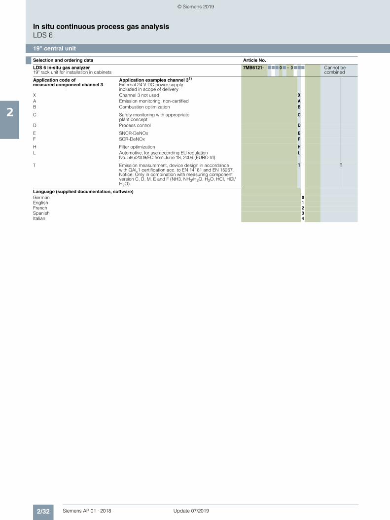
LDS 6 in-situ gas analyzer19" rack unit for installation in cabinets
7MB6121- 777 0 7 - 0 777 Cannot becombined
Click on the Article No. for the online configuration in the PIA Life Cycle Portal.
Explosion protection1)
Without, not suitable for connection to Ex sensors 0Without, suitable for connection to Ex sensors in accordance with II 1 G Ex ia op is IIC T4 Ga, II 1 D Ex ia op is IIIC T135 °C Da
1 1 1 1
Measured component Possible with application codeof the respective channel
O2 B, C A
NH3 A, E, F, L, T CNH3/H2O A, E, F, L, T D
HCl A, H, T EHCl/H2O A, H, T F
HF A, H GHF/H2O A, H H
CO C JCO/CO2 D K
CO2 A LH2O A, T M
Application code of measured component channel 1
Application examples channel 11)
A Emission monitoring, non-certified AB Combustion optimization B
C Safety monitoring with appropriate plant concept
C
D Process control D
E SNCR-DeNOx EF SCR-DeNOx F
H Filter optimization HL Automotive, for use according EU regulation
No. 595/2009/EC from June 18, 2009 (EURO VI)L
T Emission measurement, device design in accordance with QAL1 certification acc. to EN 14181 and EN 15267. Notice: Only in combination with measuring component version C, D, M, E and F (NH3, NH3/H2O, H2O, HCI, HCI/H2O).
T T
CD 6, sensor alignment kitWith 0Without 1
Application code of measured component channel 2
Application examples channel 21)
X Channel 2 not used XA Emission monitoring, non-certified AB Combustion optimization B
C Safety monitoring with appropriate plant concept
C
D Process control D
E SNCR-DeNOx EF SCR-DeNOx F
H Filter optimization HL Automotive, for use according EU regulation
No. 595/2009/EC from June 18, 2009 (EURO VI)L
T Emission measurement, device design in accordance with QAL1 certification acc. to EN 14181 and EN 15267. Notice: Only in combination with measuring component version C, D, M, E and F (NH3, NH3/H2O, H2O, HCI, HCI/H2O).
T T
1) Complete and consistent implementation of the safety concept by the plant operator must be ensured during the commissioning and operation of the in-situ laser spectrometer LDS6 or the sensor CD 6 in hazardous atmospheres.
2) The examples shown represent possible applications where appropriately configured LDS 6 solutions can be used. The user is responsible for the prevailing conditions (plant concept (possibly redundant), application of appropriate components required in addition, compliance with pos-sible directives, etc.). It is only possible to configure the same applications for multiple channels. If required, please contact Siemens for a spe-cial application (refer to page 2/41)
External 24 V DC power supply included in scope of delivery
X Channel 3 not used XA Emission monitoring, non-certified AB Combustion optimization B
C Safety monitoring with appropriate plant concept
C
D Process control D
E SNCR-DeNOx EF SCR-DeNOx F
H Filter optimization HL Automotive, for use according EU regulation
No. 595/2009/EC from June 18, 2009 (EURO VI)L
T Emission measurement, device design in accordance with QAL1 certification acc. to EN 14181 and EN 15267. Notice: Only in combination with measuring component version C, D, M, E and F (NH3, NH3/H2O, H2O, HCI, HCI/H2O).
T T
Language (supplied documentation, software)German 0English 1French 2Spanish 3Italian 4
Selection and ordering data Article No.
LDS 6 in-situ gas analyzer19" rack unit for installation in cabinets
1) The examples shown represent possible applications where appropriately configured LDS 6 solutions can be used. The user is responsible for the prevailing conditions (plant design, possibly redundant, application of appropriate components required in addition, compliance with possible directives, etc.). It is only possible to configure the same applications for multiple channels. If needed, contact Siemens for a special application (refer to page 2/41).
2) In combination with the CL/DL LDS 6 application, suitable for use to measure NH3 according to the requirements of regulation 595/2009/EC "Implementing regulations on type-approval of motor vehicles and engines with respect to emissions from heavy duty vehicles (EURO VI)" from June 18, 2009 and its regulation for implementation of number 582/2011/EC from May 25, 2011 of the Commission of the European Union.
Additional accessories
You can find more accessories and spare parts in our PIA Life Cycle Portal product selector: http://www.pia-portal.automation.siemens.com
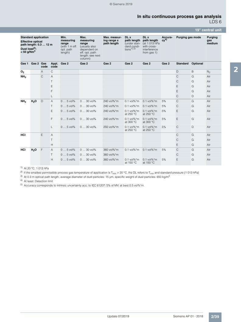
The following table lists the measuring conditions for standard applications. The listed values for the measuring range and de-tection limit (DL) are only approximate values. The exact values at the respective measuring point depend on the totality of all in-fluencing variables and can be determined by Siemens for the specific case. Note that the values for the detection limit and the maximum measuring range are based on a path length of 1 m. Longer path lengths will improve the detection limit, but not lin-early. This is due to restrictive effects such as dust load. The maximum applicable measuring ranges can only be used if per-mitted by the process conditions such as dust load.
1) All technical specifications apply to an optical path distance of 1 m in a nitrogen atmosphere under standard conditions 25 °C (or Tmin) and 1 013 hPa. The effective detection limit, the measuring range and the accuracy can be influenced by process parameters such as pressure, temperature and gas compo-sition. Not all combinations of maximum pressure and temperature can be realized with the minimum measuring ranges. If the process conditions deviate from the specifications of the standard applications, special applications are also possible on request. Complete the application questionnaire which can be found on the Internet at http://www.siemens.com/insituquestionnaire .
2) With 0.3 m effective optical path length, average diameter of dust particles: 15 µm, specific weight of dust particles: 650 kg/m3
3) At least: Detection limit4) Up to 200 °C, 5% above this5) Accuracy corresponds to intrinsic uncertainty acc. to IEC 61207: 2 % of MV (0 ... 200 °C); 2.5% of MV (0 ... 400 °C); at best 0.25 vol%*m.6) Suitable for use to measure NH3 according to requirements of Directive 595/2009/EC "Implementing regulations on type-approval of motor vehicles and
engines with respect to emissions from heavy duty vehicles (EURO VI)" from 18 June 2009 and its regulation for implementation of number 582/2011/EC from 25 May 2011 of the Commission of the European Union.
7) Device also able to operate above 400 °C to 1 000 °C. Due to decomposition of NH3 at higher temperatures, no specification can be given in these ranges.
Standard application
Effective opticalpath length: 0.3 … 12 m
Dust load2):< 50 g/Nm3
Process gas temperatureTmin … Tmax
Process gas pressurepmin … pmax
Min.measuring range(with 1 m eff. opt. path length)
Max.measuring range(also dependent on eff. opt. path length: see next column)
Max.measuring range x path length
DL x path length(under stan-dard condi-tions1)without cross-inter-ference from other gases)
DL x path length(at 1 013 hPa with cross-interference from gas 2)
Accura-cy3)
Gas 1 Gas 2 Gas code
Appl. code
Gas 1 Gas 1 Gas 1 Gas 1 Gas 1 Gas 1
O2 A C 0 … 600 °C 950 …1 050 hPa 0 … 5 vol% 0 … 100 vol% 75 vol%*m 0.1 vol%*m 2%4)
NH3 C A 0 … 150 °C 950 … 1 050 hPa 0 … 25 ppmv 0 … 500 ppmv 2 500 ppmv*m 0.5 ppmv*m 0.9 ppmv*mat 15 vol% H2O, 55 °C
2%
T 0 … 150 °C 950 … 1 050 hPa 0 … 25 ppmv 0 … 500 ppmv 2 500 ppmv*m 0.5 ppmv*m 0.9 ppmv*mat 15 vol% H2O, 55 °C
2%
E 250 … 350 °C 950 … 1 050 hPa 0 … 45 ppmv 0 … 500 ppmv 2 500 ppmv*m 0.9 ppmv*mat 250 °C
1.4 ppmv*mat 15 vol% H2O, 250 °C
2%
F 300 … 400 °C 950 … 1 050 hPa 0 … 50 ppmv 0 … 500 ppmv 2 500 ppmv*m 1 ppmv*mat 300 °C
1) At 20 °C, 1 013 hPa2) If the smallest permissible process gas temperature of application is Tmin > 20 °C, the DL refers to Tmin and standard pressure (1 013 hPa)3) At 0.3 m optical path length, average diameter of dust particles: 15 µm, specific weight of dust particles: 650 kg/m3
4) At least: Detection limit5) Accuracy corresponds to intrinsic uncertainty acc. to IEC 61207: 5% of MV; at best 0.5 vol%*m.
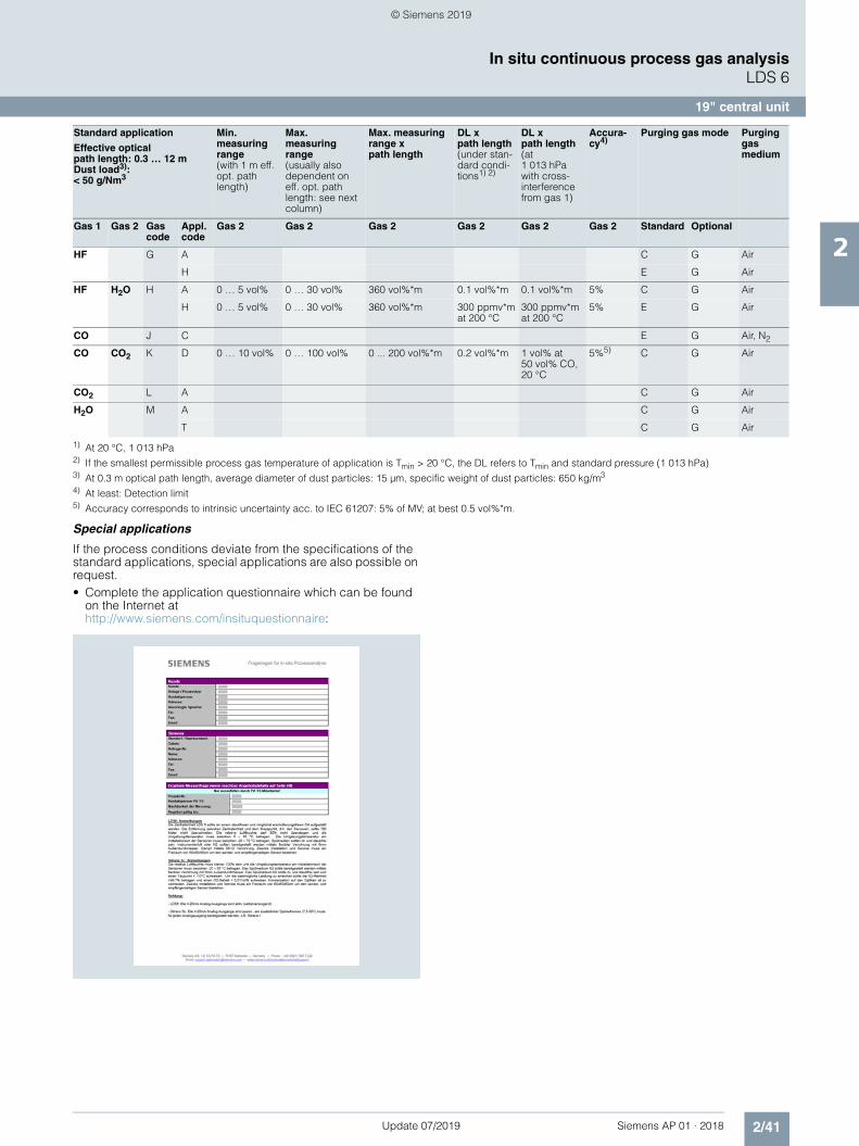
Standard application
Effective opticalpath length: 0.3 … 12 m
Dust load3):< 50 g/Nm3
Min.measuring range(with 1 m eff. opt. path length)
Max.measuring range (usually also dependent on eff. opt. path length: see next column)
Max. measur-ing range x path length
DL xpath length(under stan-dard condi-tions1) 2)
DL x path length(at 1 013 hPa with cross-interference from gas 1)
Accura-cy4)
Purging gas mode Purging gas medium
Gas 1 Gas 2 Gas code
Appl. code
Gas 2 Gas 2 Gas 2 Gas 2 Gas 2 Gas 2 Standard Optional
O2 A C D B N2
NH3 C A C G Air
T C G Air
E E G Air
F E G Air
L C D Air
NH3 H2O D A 0 … 5 vol% 0 … 30 vol% 240 vol%*m 0.1 vol%*m 0.1 vol%*m 5% C G Air
T 0 … 5 vol% 0 … 30 vol% 240 vol%*m 0.1 vol%*m 0.1 vol%*m 5% C G Air
E 0 … 5 vol% 0 … 30 vol% 240 vol%*m 0.1 vol%*mat 250 °C
0.1 vol%*mat 250 °C
5% E G Air
F 0 … 5 vol% 0 … 30 vol% 240 vol%*m 0.1 vol%*mat 300 °C
0.1 vol%*mat 300 °C
5% E G Air
L 0 … 5 vol% 0 … 30 vol% 250 vol%*m 0.1 vol%*mat 250 °C
0.1 vol%*mat 250 °C
5% C D Air
HCl E A C G Air
T C G Air
H E G Air
HCl H2O F A 0 … 5 vol% 0 … 30 vol% 360 vol%*m 0.1 vol%*m 0.1 vol%*m 5% C G Air
T 0 … 5 vol% 0 … 30 vol% 360 vol%*m C G Air
H 0 … 5 vol% 0 … 30 vol% 360 vol%*m 0.1 vol%*mat 150 °C
1) All technical specifications apply to an optical path distance of 1 m in a nitrogen atmosphere under standard conditions 25 °C (or Tmin) and 1 013 hPa. The effective detection limit, the measuring range and the accuracy can be influenced by process parameters such as pressure, temperature and gas compo-sition. Not all combinations of maximum pressure and temperature can be realized with the minimum measuring ranges. If the process conditions deviate from the specifications of the standard applications, special applications are also possible on request. Complete the application questionnaire which can be found on the Internet at http://www.siemens.com/insituquestionnaire .
2) With 0.3 m effective optical path length, average diameter of dust particles: 15 µm, specific weight of dust particles: 650 kg/m3
3) At least: Detection limit4) Up to 200 °C, 5% above this5) Accuracy corresponds to intrinsic uncertainty acc. to IEC 61207: 2 % of MV (0 ... 200 °C); 2.5% of MV (0 ... 400 °C); at best 0.25 vol%*m.6) Suitable for use to measure NH3 according to requirements of Directive 595/2009/EC "Implementing regulations on type-approval of motor vehicles and
engines with respect to emissions from heavy duty vehicles (EURO VI)" from 18 June 2009 and its regulation for implementation of number 582/2011/EC from 25 May 2011 of the Commission of the European Union.
7) Device also able to operate above 400 °C to 1 000 °C. Due to decomposition of NH3 at higher temperatures, no specification can be given in these ranges.
1) At 20 °C, 1 013 hPa2) If the smallest permissible process gas temperature of application is Tmin > 20 °C, the DL refers to Tmin and standard pressure (1 013 hPa)3) At 0.3 m optical path length, average diameter of dust particles: 15 µm, specific weight of dust particles: 650 kg/m3
4) At least: Detection limit5) Accuracy corresponds to intrinsic uncertainty acc. to IEC 61207: 5% of MV; at best 0.5 vol%*m.
Special applications
If the process conditions deviate from the specifications of the standard applications, special applications are also possible on request.• Complete the application questionnaire which can be found
on the Internet at http://www.siemens.com/insituquestionnaire:
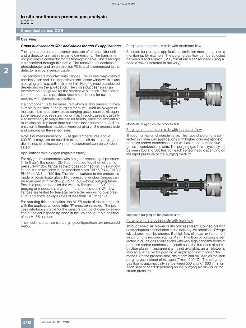
Cross-duct sensors CD 6 and cables for non-Ex applications
The standard cross-duct sensor consists of a transmitter unit and a detector unit with the same dimensions. The transmitter unit provides a connector for the fiber-optic cable. The laser light is transmitted through this cable. The receiver unit contains a photodetector and an electronics PCB, and is connected to the detector unit by a sensor cable.
The sensors are mounted onto flanges. The easiest way to avoid condensation and dust deposits on the sensor windows is to use a purging gas, e.g. with instrument air. Purging must be selected depending on the application. The cross-duct sensors can therefore be configured for the respective situation. The applica-tion reference table provides recommendations for suitable purging with standard applications.
If a component is to be measured which is also present in mea-surable quantities in the purging medium - such as oxygen or moisture - it is necessary to use purging gases such as nitrogen, superheated process steam or similar. In such cases it is usually also necessary to purge the sensor heads, since the ambient air must also be displaced here out of the laser beam path. A differ-entiation is therefore made between purging on the process side and purging on the sensor side.
Note: For measurement of O2 at gas temperatures above 600 °C, it may also be possible to tolerate air as the purging me-dium since its influence on the measurement can be compen-sated.
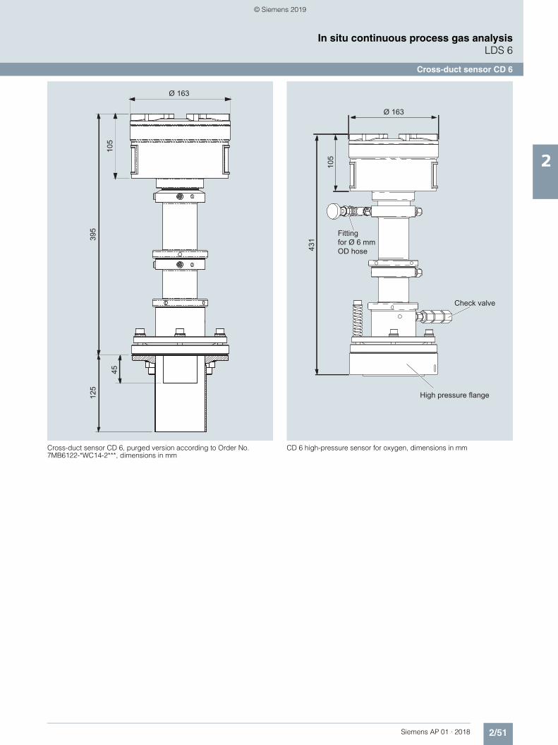
Applications with oxygen (high-pressure)
For oxygen measurements with a higher process gas pressure (1 to 5 bar), the sensor CD 6 can be used together with a high-pressure window flange as the process connection. This window flange is also available in the standard sizes DN 65/PN 6, DN 80/PN 16 or ANSI 4"/150 lbs. The optical surface to the process is made of borosilicate glass. High-pressure window flanges can be equipped with window purging, but without purging tubes. Possible purge modes for the window flanges are "A-C" (no purging or moderate purging on the process side). Window flanges are tested for leakage before delivery using overpres-sure, and show leakage rates of less than 10-5 mbar·l/s.
For ordering this application, the MLFB code of the central unit with the application code letter "P" must be selected. The pro-cess interface suitable for the sensors can be chosen by selec-tion of the corresponding code in the 6th configurable position of the MLFB number.
The most important sensor purging configurations are presented below:
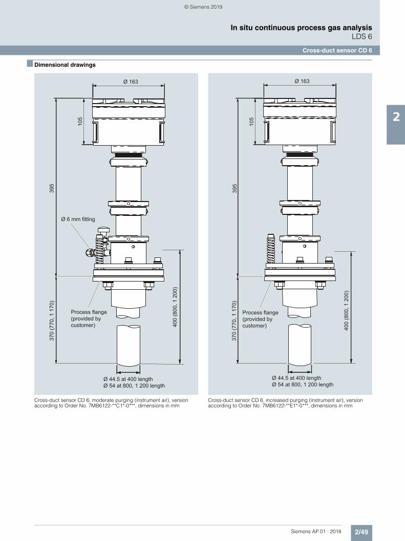
Purging on the process side with moderate flow
Selected for pure gas applications, emission monitoring, inertia monitoring, for example. The purging gas flow can be adjusted between 0 and approx. 120 l/min at each sensor head using a needle valve (included in delivery).
Moderate purging on the process side
Purging on the process side with increased flow
Through omission of needle valve. This type of purging is se-lected in crude gas applications with higher concentrations of particles and/or condensation as well as in non-purified flue gases in combustion plants. The purging gas flow is typically set between 200 and 500 l/min on each sensor head depending on the input pressure of the purging medium.
Increased purging on the process side
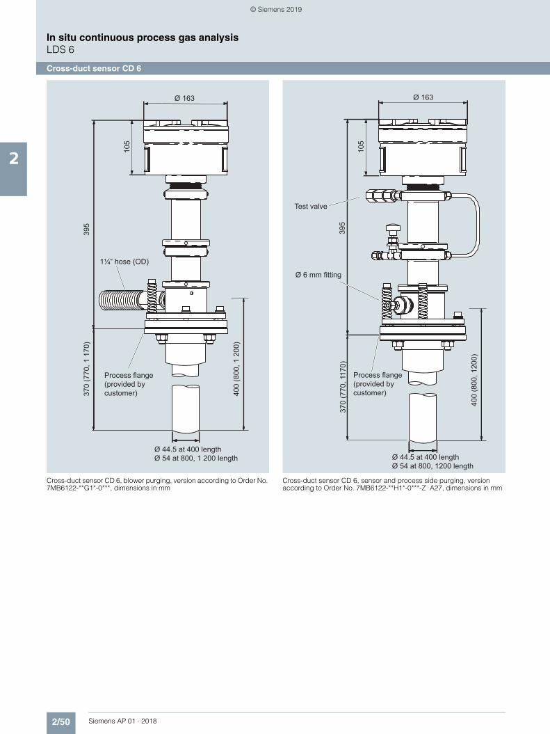
Purging on the process side with high flow
Through use of air blower or dry process steam. Connectors with hose adapters are included in the delivery. An additional Swage-lok adapter must be ordered if a high flow of steam or instrument air purging is required (option A27). This type of purging is se-lected in crude gas applications with very high concentrations of particles and/or condensation such as in the furnaces of com-bustion plants. If instrument air is not available, an air blower is also an alternative for purging in applications with lower de-mands. On the process side, dry steam can be used as the inert purging gas instead of nitrogen (Tmax. 240 °C). The purging gas flow is automatically set between 500 and <1 000 l/min on each sensor head depending on the purging air blower or the steam pressure.
Increased purging on the process side, with hose connection adapter
Purging on sensor side
Can be combined with any purging mode on the process side, and is always selected if the ambient air must never have an in-fluence on the measurement. The volumes within the sensor head are then continuously purged with an O2-free gas (with H2O-free gas in the case of moisture measurement).
Note
With purging on the process side, it may be necessary to use non-return valves to ensure no process gas can enter the purg-ing gas line in the event of failure of the purging gas supply. This applies especially in the case of cascaded process and sensor purging where there is otherwise the danger that, for example, corrosive process gases could enter the sensor enclosure.
Sensor configuration with high purging on the process side, with 6 mm joint for use with steam, and with N2 purging on the sensor side
The purging media used on the process side flow through purg-ing gas tubes into the process gas flow. The tubes extend a few centimeters into the process area, and usually receive a flow of process gas from the side. This results in a wedge being gener-ated in the inlet zone of the purging gas. The effective measuring path in the process gas is therefore well-defined as the distance between the ends of the two purging gas inlet tubes.
Cross-duct sensor CD 6: Options and accessories
Sensor alignment kit
Includes a battery-operated visible light source, a centering aid with crosshair, and two hook spanners for opening the optics tube of the sensors.
Please note: the sensor alignment kit is not explosion protected.
Installation requirements for the cross-duct sensors CD 6, dimensions in mm
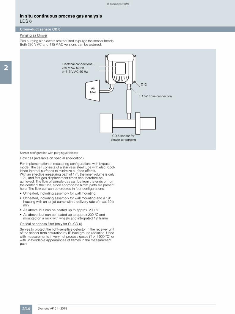
Two purging air blowers are required to purge the sensor heads. Both 230 V AC and 115 V AC versions can be ordered.
Sensor configuration with purging air blower
Flow cell (available on special application)
For implementation of measuring configurations with bypass mode. The cell consists of a stainless steel tube with electropol-ished internal surfaces to minimize surface effects.With an effective measuring path of 1 m, the inner volume is only 1.2 l, and fast gas displacement times can therefore be achieved. The flow of sample gas can be from the ends or from the center of the tube, since appropriate 6 mm joints are present here. The flow cell can be ordered in four configurations:• Unheated, including assembly for wall mounting• Unheated, including assembly for wall mounting and a 19"
housing with an air jet pump with a delivery rate of max. 30 l/min
• As above, but can be heated up to approx. 200 °C • As above, but can be heated up to approx 200 °C and
mounted on a rack with wheels and integrated 19" frame
Optical bandpass filter (only for O2-CD 6)
Serves to protect the light-sensitive detector in the receiver unit of the sensor from saturation by IR background radiation. Used with measurements in very hot process gases (T > 1 000 °C) or with unavoidable appearances of flames in the measurement path.
Ø12
Electrical connections:230 V AC 50 Hzor 115 V AC 60 Hz
Design Transmitter and detector units, con-nected by a sensor cable
Materials Stainless steel (1.4305/303), alumi-num
Installation Vertical or parallel to the gas flow
Laser protection class Class 1, safe to the eye
Explosion protection II 1 G Ex ia op to IIC T4 GaII 1 D Ex ia op to IIIC T135 °C Da
A defined leak rate can only be guar-anteed when using high-pressure window flanges. Otherwise, it may be necessary for the owner to carry out an evaluation in accordance with ATEX DEMKO 06 ATEX 139648X;IECEx UL 13.0029X
Design, enclosure
Degree of protection IP65
Dimensions Diameter: 163, L: 450 mm
Purging gas tube in mm 400 (370 net) x 44 x 40800 (770 net) x 54 x 401 200 (1 170 net) x 54 x 40
Please note:• For purging tubes with a length of 800 and 1 200 mm, the wall thickness
must not exceed 200 mm with DN 65/PN 6 connections. To carry out mea-surements with thicker walls, please contact Siemens.
• The optimum adjustment of the flanges can change with high differences in temperature between the process and environment depending on the type of assembly.
Electrical characteristics
Power supply 24 V DC, supply from central unit via hybrid cable
Power consumption < 2 W with non-Ex configuration, max. 0.6 W with Ex configuration
Climatic conditions
Sensor temperature
Non-Ex -20 ... +70 °C in operation
-30 ... +70 °C during transport and storage
Ex -20 ... +60 °C in operation
-30 ... +70 °C during transport and storage
Humidity < 95 % RH, above dew point
Pressure 800 ... 1 100 hPa
Temperature range on the sensor side of the process interface (connection plate)
-20 ... +70 °C
Measuring conditions
Measurement path 0.3 ... 12 m (other path lengths on request)
Dust load The influence of dust is very complex and depends on the path length and particle size. The optical attenuation increases exponentially at longer path lengths. Smaller particles also have a very large influence on the optical attenuation. With high dust load, long path length and small par-ticle size, the technical support at Siemens should be consulted.
Purging
Nitrogen is permissible as the purging gas for the sensor side. Nitrogen, steam, air and gases which are not subject to the pressure equipment directive Cat. 2 are permissible as purging gases for the process side.
Purging with instrument air, N2• Max. overpressure in the sensor < 500 hPa• Quality
- Instrument air According to ISO 8573-1:2010 [2:3:3]
Note: It is sufficient if the pressure condensation point is min. 10 K below the minimum ambient tempera-ture.
- Nitrogen Purity better than 99.7 %. For oxygen measurements, an O2 content < 0.01% in the purging gas.Optical path length ≥ 1 m, min. 5% oxygen in the process gas.
• Maximum flow rate (process purg-ing)
500 l/min
• Dew point Benchmark: < -10 °C, condensation on the optics must be avoided
Blower purging• Maximum counter pressure 40 hPa • Maximum flow rate 850 l/min• Power consumption 370 W• Degree of protection (fan) IP54, cover required to protect
against rain
Steam purging• Steam conditioning Overheated• Maximum temperature 240 °C• Minimum pressure > 4 000 hPa• Maximum pressure 16 000 hPa, refers to a volume flow of
Configuration hybrid cable Two optical fibers and two twisted copper wires in one cable for 24 V DC. Single-mode optical fiber fabri-cated at both ends with E2000 angle connectors. Multimode optical fiber configured at both ends with SMA connectors.
Cable is flame-retardant, very good resistance to oil, gasoline, acids and alkalis, outer sheath UV-resistant
Cable sheath Oil-resistant polyurethane
Dimensions • An external power supply must be additionally ordered for > 500 m
• For installation in hazardous zones, non-intrinsically-safe cables have to be spatially separated from intrinsi-cally-safe lines
• Diameter < 8.5 mm• Length • Use in non-hazardous and Ex
Zone 2: Up to 700 m• Use in Ex Zone 0 and Zone 1: Up to
250 m
Weight 75 kg/km
Maximum tensile force 200 N
Maximum lateral pressure 1 000 N/cm
Impact resistance 200 N/cm
Maximum tensile strength 500 N
Minimum bending radius 12 cm
Climatic conditions
Ambient temperature -40 ... +70 °C during transport, stor-age and operation
-5 ... +50 °C during cable installation
Humidity < 95% rel. humidity, above dew point (in operation and storage)
Hybrid cableNo hybrid cable XStandard length• 5 m A• 10 m B• 25 m E• 40 m G• 50 m HCustomized length (specified in complete meters) Z
1) Complete and consistent implementation of the safety concept by the plant operator must be ensured during the commissioning and operation of the in-situ laser spectrometer LDS6 or the sensor CD 6 in hazardous atmospheres.
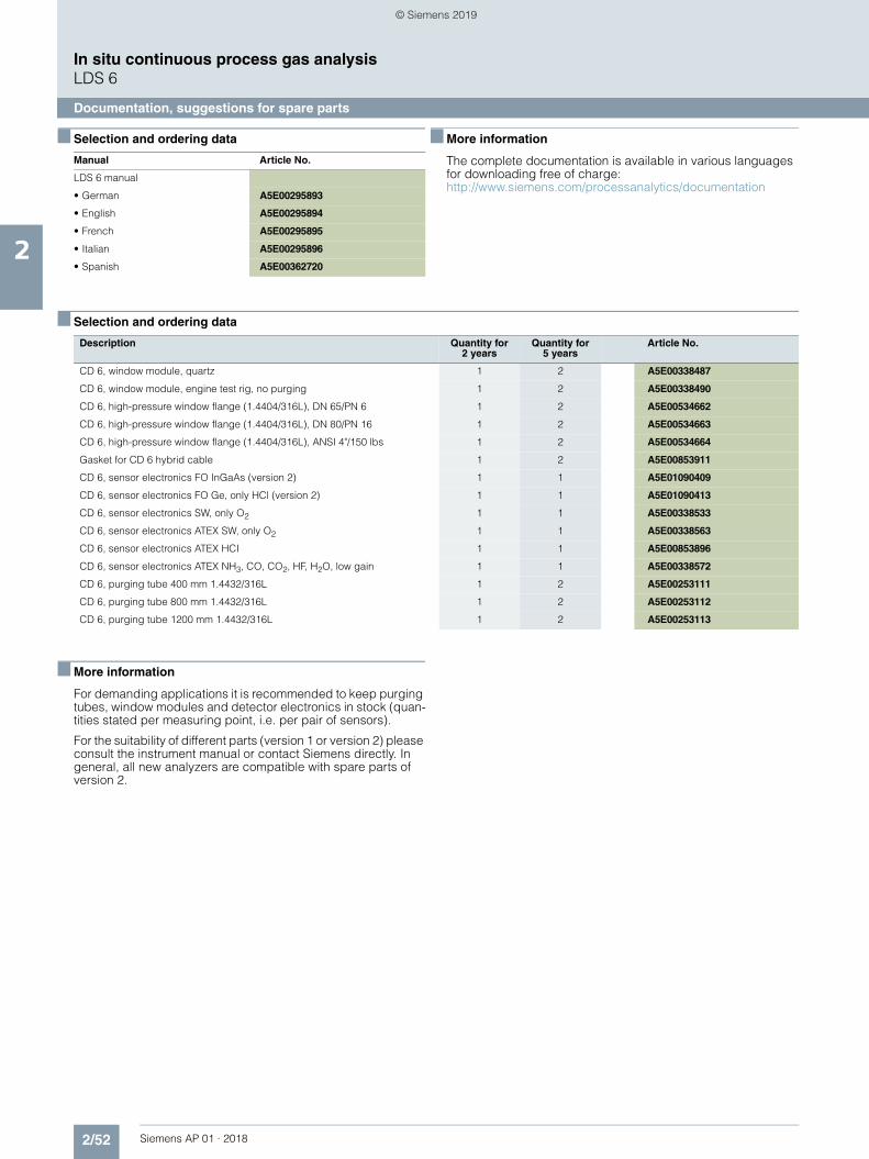
The complete documentation is available in various languages for downloading free of charge:http://www.siemens.com/processanalytics/documentation
■ Selection and ordering data
■ More information
For demanding applications it is recommended to keep purging tubes, window modules and detector electronics in stock (quan-tities stated per measuring point, i.e. per pair of sensors).
For the suitability of different parts (version 1 or version 2) please consult the instrument manual or contact Siemens directly. In general, all new analyzers are compatible with spare parts of version 2.
Manual Article No.
LDS 6 manual
• German A5E00295893
• English A5E00295894
• French A5E00295895
• Italian A5E00295896
• Spanish A5E00362720
Description Quantity for 2 years
Quantity for 5 years
Article No.
CD 6, window module, quartz 1 2 A5E00338487
CD 6, window module, engine test rig, no purging 1 2 A5E00338490