VOLUME 24, ISSUE 6 APRIL 2011 ® IN THIS ISSUE INDUSTRY NEWS AND DEVELOPMENTS 1 TEST BENCH 11 Wavecor and Beyma Home and Pro Drivers By Vance Dickason ACOUSTIC PATENTS INDUSTRY WATCH 22 24 29 Products & Services Index SPOTLIGHT 5 ALMA 2011 Winter Symposium Pt. 2 By Rob Baum, Spiro Iraclianos, Matt Lyons, Sean Olive, and Mike Klasco Industry News and Developments By Vance Dickason Publisher Ed Dell Receives ALMA Driver Award ast month’s ALMA 2011 Winter Symposium Part 1 announced the winners of the ALMA Driver Awards. Among the distinguished recipients was Audio Amateur’s founder and CEO, publisher Ed Dell (Photo 1). Because I was not certain that all Voice Coil’s readers are aware of Mr. Dell’s contribution to the loudspeaker industry, I will reprint the intro- duction I wrote that was read at the Driver Awards presentation: When I was asked to write an introduction for the pre- sentation of ALMA’s first Driver Award to Ed Dell, the first thing that came to mind was to wonder how many audio professionals realize the impact Ed has had on the loudspeaker industry over the years. The story began in 1970 when Mr. Dell founded Audio Amateur Inc. in Swarthmore, Penn., and commenced publication of The Audio Amateur, a quar- terly magazine dedicated to do-it-yourself audio enthusiasts. While Audio Amateur included articles on all aspects of hi-fi, it immediately attracted the information-hungry group of loudspeaker enthusiasts and resulted in a substantial percent- Cutaway of Beyma’s SW1300Nd cone assembly, p. 11. What was discussed at ALMA’s roundtable sessions? See p. 5. By James Croft By Vance Dickason
Transcript
V O L U M E 2 4 , I S S U E 6 A P R I L 2 0 1 1
®
IN THIS ISSUEINDUSTRY NEWS AND DEVELOPMENTS
1
TEST BENCH11Wavecor and Beyma Home and Pro DriversBy Vance Dickason
ACOUSTIC PATENTS
INDUSTRY WATCH
22
24
29 Products & Services Index
SPOTLIGHT5ALMA 2011 Winter Symposium Pt. 2 By Rob Baum, Spiro Iraclianos, Matt Lyons, Sean Olive, and Mike Klasco
Industry News and DevelopmentsBy Vance Dickason
Publisher Ed Dell Receives ALMA Driver Award
�ast month’s ALMA 2011 Winter Symposium Part 1 announced the winners of the ALMA Driver Awards.
Among the distinguished recipients was Audio Amateur’s founder and CEO, publisher Ed Dell (Photo 1). Because I was not certain that all Voice Coil’s readers are aware of Mr. Dell’s contribution to the loudspeaker industry, I will reprint the intro-duction I wrote that was read at the Driver Awards presentation:
When I was asked to write an introduction for the pre-sentation of ALMA’s first Driver Award to Ed Dell, the first thing that came to mind was to wonder how many audio professionals realize the impact Ed has had on the loudspeaker industry over the years. The story began in 1970 when Mr. Dell founded Audio Amateur Inc. in Swarthmore, Penn., and commenced publication of The Audio Amateur, a quar-terly magazine dedicated to do-it-yourself audio enthusiasts. While Audio Amateur included articles on all aspects of hi-fi, it immediately attracted the information-hungry group of loudspeaker enthusiasts and resulted in a substantial percent-
age of the magazine’s content relating to speaker design, especially transmission line, electrostatic, and folded horn speakers. Because of the high level of enthusiasm for anything pertaining to loudspeakers, Ed decided that a separate magazine devoted just to loudspeaker technology was in order. This resulted in the publication of Speaker Builder magazine in 1980. His first two contributing editors were Nelson Pass and Marshall Leach. SpeakerBuilder was highly successful and gave a forum for other important contributors including Joe D’Appolito, Vance Dickason, Robert Bullock, and Bruce Edgar.
Recognizing the need for a vehicle that focused just on the professional side of the loudspeaker industry, Ed put together another new publication, entitled Voice Coil; he recruited loudspeaker engineer, consultant, and author Vance Dickason to write it. Now in its 24th year, the four-page black and white newsletter has blossomed into a 40-page full-color magazine that, over the years, fea-tured the contributions of numerous industry professionals including Patrick Turnmire, Mike Klasco, Steve Mowry, Charlie Hughes, Jim Croft, and others.
In over 40 years of publishing, Ed Dell has brought the world of loudspeakers a number of books includ-ing the 2nd through 7th editions of Vance Dickason’s Loudspeaker Design Cookbook, Joseph D’Appolito’s Testing Loudspeakers, Robert Bullock’s Bullock on Boxes, and Roger Sanders’ Electrostatic Loudspeaker Design Cookbook. In addition to articles and books on loud-
speakers and audio technologies, Ed and his publi-cations have interviewed many of the audio indus-try’s greatest luminaries including Henry Kloss, Peter Baxandall, Peter Walker, P.G.A. H. Voigt, and Neville Thiele. Given all of this, I can’t think of a more deserv-ing individual to receive ALMA’s first Driver Award than Edward T. Dell. Congratulations, Ed!
AXPONA 2011The Stereophile magazine-sponsored AXPONA (Audio Expo North America) consumer audio show will take place April 14-17, at the downtown Atlanta, Ga. Sheraton Hotel. Exhibitors include Acoustic Zen, Adam Audio, Advanced Transduction, Aspara Acoustics, Audience, Audio Physic, Audioengine, Axis Audio Loudspeakers, B&W Group, Carnegie Acoustics, Classic Audio Loudspeakers, Definitive Technology, Emotiva Audio, Induction Dynamics, JL Audio, Krell Industries, Legacy Audio, Leon Speakers, Linkwitz Lab, Linn Products, Madisound Speaker Components, MBL, McIntosh Labs, Naim Audio, Paradigm Speakers, Phase Technology, PSB Speakers, Quad, Rosso Fiorentino Electroacoustics, Sanders Sound Systems, Scaena Loudspeakers, Selah Audio, Sonist Loudspeakers, Spendor, Totem Acoustic, Transmission Audio, Tyler Acoustics, Vandersteen Audio, Wharfedale Loudspeakers, and YG Acoustics. For more, visit the AXPONA website www.axpona.com. VC
ALMA 2011 Winter Symposium (Part 2)By Rob Baum, Spiro Iraclianos, Matt Ly-ons, Sean Olive, and Mike Klasco
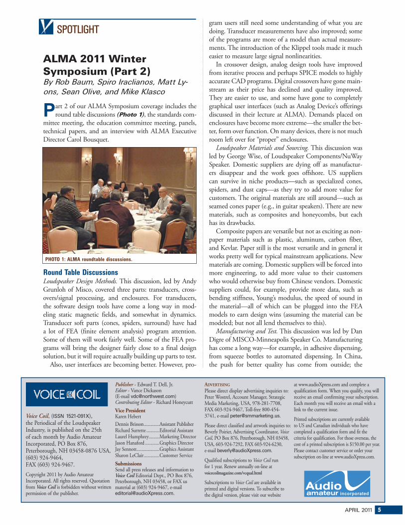
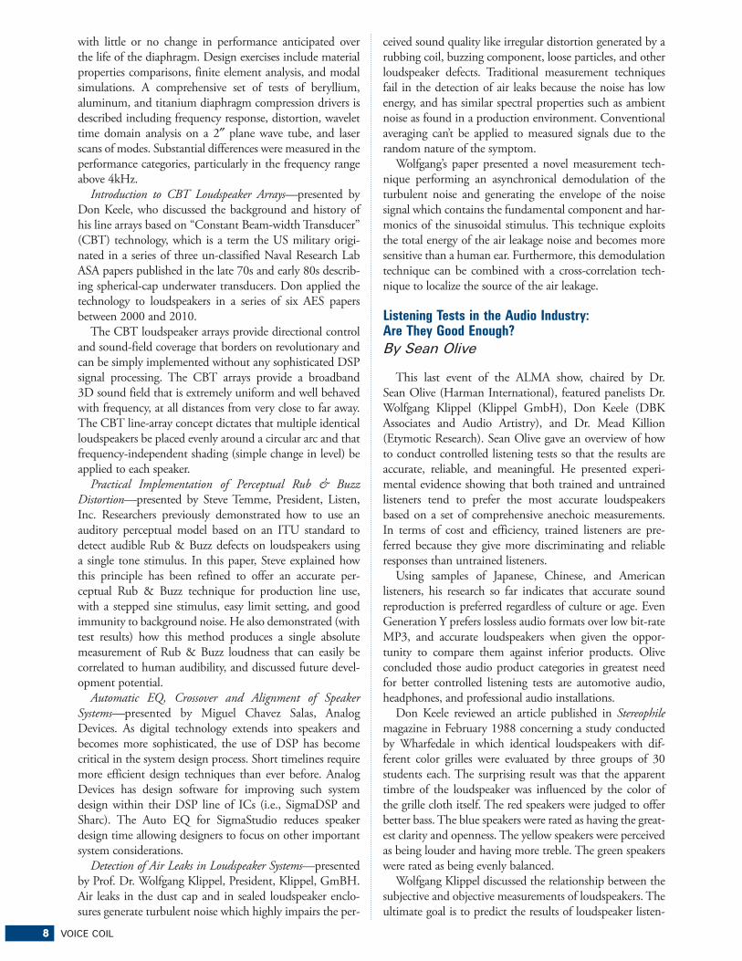
�art 2 of our ALMA Symposium coverage includes the round table discussions (Photo 1), the standards com-
mittee meeting, the education committee meeting, panels, technical papers, and an interview with ALMA Executive Director Carol Bousquet.
Round Table DiscussionsLoudspeaker Design Methods. This discussion, led by Andy Grunloh of Misco, covered three parts: transducers, cross-overs/signal processing, and enclosures. For transducers, the software design tools have come a long way in mod-eling static magnetic fields, and somewhat in dynamics. Transducer soft parts (cones, spiders, surround) have had a lot of FEA (finite element analysis) program attention. Some of them will work fairly well. Some of the FEA pro-grams will bring the designer fairly close to a final design solution, but it will require actually building up parts to test.
Also, user interfaces are becoming better. However, pro-
gram users still need some understanding of what you are doing. Transducer measurements have also improved; some of the programs are more of a model than actual measure-ments. The introduction of the Klippel tools made it much easier to measure large signal nonlinearities.
In crossover design, analog design tools have improved from iterative process and perhaps SPICE models to highly accurate CAD programs. Digital crossovers have gone main-stream as their price has declined and quality improved. They are easier to use, and some have gone to completely graphical user interfaces (such as Analog Device’s offerings discussed in their lecture at ALMA). Demands placed on enclosures have become more extreme—the smaller the bet-ter, form over function. On many devices, there is not much room left over for “proper” enclosures.
Loudspeaker Materials and Sourcing. This discussion was led by George Wise, of Loudspeaker Components/NuWay Speaker. Domestic suppliers are dying off as manufactur-ers disappear and the work goes offshore. US suppliers can survive in niche products—such as specialized cones, spiders, and dust caps—as they try to add more value for customers. The original materials are still around—such as seamed cones paper (e.g., in guitar speakers). There are new materials, such as composites and honeycombs, but each has its drawbacks.
Composite papers are versatile but not as exciting as non-paper materials such as plastic, aluminum, carbon fiber, and Kevlar. Paper still is the most versatile and in general it works pretty well for typical mainstream applications. New materials are coming. Domestic suppliers will be forced into more engineering, to add more value to their customers who would otherwise buy from Chinese vendors. Domestic suppliers could, for example, provide more data, such as bending stiffness, Young’s modulus, the speed of sound in the material—all of which can be plugged into the FEA models to earn design wins (assuming the material can be modeled; but not all lend themselves to this).
Manufacturing and Test. This discussion was led by Dan Digre of MISCO-Minneapolis Speaker Co. Manufacturing has come a long way—for example, in adhesive dispensing, from squeeze bottles to automated dispensing. In China, the push for better quality has come from outside; the
Voice Coil, (ISSN 1521-091X), the Periodical of the Loudspeaker Industry, is published on the 25th of each month by Audio Amateur Incorporated, PO Box 876, Peterborough, NH 03458-0876 USA, (603) 924-9464, FAX (603) 924-9467.
Copyright 2011 by Audio Amateur Incorporated. All rights reserved. Quotation from Voice Coil is forbidden without written permission of the publisher.
Publisher - Edward T. Dell, Jr.Editor - Vance Dickason (E-mail [email protected])Contributing Editor - Richard Honeycutt
Vice PresidentKaren HebertDennis Brisson .............Assistant PublisherRichard Surrette ...........Editorial AssistantLaurel Humphrey.........Marketing DirectorJason Hanaford ............Graphics DirectorJay Sennott ...................Graphics AssistantSharon LeClair .............Customer ServiceSubmissionsSend all press releases and information to Voice Coil Editorial Dept., PO Box 876, Peterborough, NH 03458, or FAX us material at (603) 924-9467, e-mail [email protected].
ADVERTISING
Please direct display advertising inquiries to: Peter Wostrel, Account Manager, Strategic Media Marketing, USA, 978-281-7708, FAX 603-924-9467, Toll-free 800-454-3741, e-mail [email protected].
Please direct classified and artwork inquiries to: Beverly Poirier, Advertising Coordinator, Voice Coil, PO Box 876, Peterborough, NH 03458, USA, 603-924-7292, FAX 603-924-6230, e-mail [email protected].
Qualified subscriptions to Voice Coil run for 1 year. Renew annually on-line at voicecoilmagazine.com/vcqual.html
Subscriptions to Voice Coil are available in printed and digital versions. To subscribe to the digital version, please visit our website
at www.audioXpress.com and complete a qualification form. When you qualify, you will receive an email confirming your subscription. Each month you will receive an email with a link to the current issue.
Printed subscriptions are currently available to US and Canadian individuals who have completed a qualification form and fit the criteria for qualification. For those overseas, the cost of a printed subscription is $150.00 per year. Please contact customer service or order your subscription on-line at www.audioXpress.com.
PHOTO 1: ALMA roundtable discussions.
6 VOICE COIL
factory usually will not do it themselves. Chinese factories (in general, there are exceptions) are not so great at finding solutions on their own. Equipment in the factories needs to be simple to use. Labor shortages and high turnover in China also make manufacturing more challenging. The US workforce is more stable.
In China, it is also true that it is hard to find tight tol-erance work, due to both the higher skill levels required and less demand for such work. Quality in China is clearly improving, but it usually requires a push from outside. There have been improvements in equipment and documentation. Automated end-of-line testing has also improved; to catch defects that otherwise would have gone through. It is tougher to get good quality out of a factory you don’t control; customers sourcing from Chinese facto-ries did not set up the corporate culture.
Aesthetic demands have increased; looks matter at both the finished product and sub assembly level—for example, neat glue lines and centering of parts. Specifications are important, and so is the process by which a product is manu-factured. Changes upstream may have consequences down-stream (e.g., change a solvent somewhere, and glue adhesion may be affected later in the manufacturing process).
Failure Mode and Effects Analysis (FMEA) is a procedure in product development and operations management for analysis of potential failure modes within a system, for clas-sification by the severity and likelihood of failures. There is improvement in FMEA in China, but it takes time and paperwork.
Automated testing has also improved, but in China you need to be sure you are using the real equipment and software, not counterfeits. End-of-line testing is commonly done for most products, except for the larger items such as pro audio speakers in large enclosures. Is automation an answer to bringing manufacturing back to the US and Europe? It is useful in Asia, particularly in high volume manufacturing. JBL’s fancy automated production lines have disappeared as production went to China. One fact pushing against the return of manufacturing is that factories in general should be close to the final customer for competi-tive advantage. As the Chinese domestic market continues to expand rapidly, that is all the more reason for factories to move and stay in China.
Winter 2011 Standards Symposium ReportThe ALMA International Standards Committee held an open committee meeting, which was attended by nine participants from various areas of the Loudspeaker and Consumer Electronics Industries. In an effort to further strengthen the potential collaboration between ALMA and CEA, the Senior Director of Technology and Standards attended to obtain an understanding of ALMA operations and offered ideas for future efforts. Additionally, the com-mittee reviewed progress that was made during the 2010 calendar year.
Standards have been posted on the newly updated ALMA International website. The Master List was reviewed and ideas for updating and maintaining the collection were
discussed. You can view the current ALMA Standards at www.almainternational.org/alma-standards. The commit-tee has many ideas and potential action items to work on to improve the value of the standards that ALMA is endorsing. Additional meetings are being planned for 2011. Please visit the ALMA International website or ALMA via LinkedIn for additional upcoming detailed information.
ALMA Loudspeaker Education CommitteeThe ALMA Education Committee, chaired by Matt Lyons, adjunct professor at the Peabody Conservatory of the Johns Hopkins University, welcomed many new members to its meeting and agreed to continue to focus on the develop-ment of the student loudspeaker design competition with outreach to select institutions of higher education and is working to refine competition criteria. Outreach tactics will consist more of a focused, one-to-one approach in 2011. Efforts in 2010 proved to be elusive in reaching students because the committee convened only mid-year; however, much was learned and accomplished by the committee along the way with many new contacts and affiliations made that will serve future objectives. Each committee member will work to mentor at least one school to produce an ALMA student section with the aim of recruiting par-ticipation in the student design competition, and ALMA Education committee members will work one-on-one men-toring students for the contest.
The committee is updating the student design contest rules and will schedule its first teleconference soon to review which institutions will be assigned to which education com-mittee members. The first phase of the student competition will be a “design on paper.” Then a round of five candidates will be selected and five designs will be built. The ALMA education committee is soliciting the greater loudspeaker industry for support for the construction of the five final-ists’ pairs of loudspeakers to be judged by industry experts at the next ALMA Winter Symposium. Final judging will be chaired by Earl Geddes. One of the main goals of the ALMA education committee is to work with students to help shape the future of loudspeaker design and to foster membership in ALMA.
Contest details will be posted on the ALMA website. Educators are encouraged to contact Matt Lyons through the ALMA website for more information.
Technical PapersThere were five excellent technical papers presented at ALMA as follows:
A High Performance Beryllium Dome Diaphragm for Large Format Compression Drivers—presented by Marshall Buck, PhD., President, Psychotechnology, Inc., with co-authors Gordon Simmons, Peter Andrews, and Sam Saye (Materion Electrofusion, formerly Brush Wellman, Electrofusion Products). This paper details the development, manu-facture, and testing of a new large format compression driver diaphragm using a beryllium dome and new type of polymer surround that exhibits improved performance. This design promises to give long life and good reliability
8 VOICE COIL
with little or no change in performance anticipated over the life of the diaphragm. Design exercises include material properties comparisons, finite element analysis, and modal simulations. A comprehensive set of tests of beryllium, aluminum, and titanium diaphragm compression drivers is described including frequency response, distortion, wavelet time domain analysis on a 2″ plane wave tube, and laser scans of modes. Substantial differences were measured in the performance categories, particularly in the frequency range above 4kHz.
Introduction to CBT Loudspeaker Arrays—presented by Don Keele, who discussed the background and history of his line arrays based on “Constant Beam-width Transducer” (CBT) technology, which is a term the US military origi-nated in a series of three un-classified Naval Research Lab ASA papers published in the late 70s and early 80s describ-ing spherical-cap underwater transducers. Don applied the technology to loudspeakers in a series of six AES papers between 2000 and 2010.
The CBT loudspeaker arrays provide directional control and sound-field coverage that borders on revolutionary and can be simply implemented without any sophisticated DSP signal processing. The CBT arrays provide a broadband 3D sound field that is extremely uniform and well behaved with frequency, at all distances from very close to far away. The CBT line-array concept dictates that multiple identical loudspeakers be placed evenly around a circular arc and that frequency-independent shading (simple change in level) be applied to each speaker.
Practical Implementation of Perceptual Rub & Buzz Distortion—presented by Steve Temme, President, Listen, Inc. Researchers previously demonstrated how to use an auditory perceptual model based on an ITU standard to detect audible Rub & Buzz defects on loudspeakers using a single tone stimulus. In this paper, Steve explained how this principle has been refined to offer an accurate per-ceptual Rub & Buzz technique for production line use, with a stepped sine stimulus, easy limit setting, and good immunity to background noise. He also demonstrated (with test results) how this method produces a single absolute measurement of Rub & Buzz loudness that can easily be correlated to human audibility, and discussed future devel-opment potential.
Automatic EQ, Crossover and Alignment of Speaker Systems—presented by Miguel Chavez Salas, Analog Devices. As digital technology extends into speakers and becomes more sophisticated, the use of DSP has become critical in the system design process. Short timelines require more efficient design techniques than ever before. Analog Devices has design software for improving such system design within their DSP line of ICs (i.e., SigmaDSP and Sharc). The Auto EQ for SigmaStudio reduces speaker design time allowing designers to focus on other important system considerations.
Detection of Air Leaks in Loudspeaker Systems—presented by Prof. Dr. Wolfgang Klippel, President, Klippel, GmBH. Air leaks in the dust cap and in sealed loudspeaker enclo-sures generate turbulent noise which highly impairs the per-
ceived sound quality like irregular distortion generated by a rubbing coil, buzzing component, loose particles, and other loudspeaker defects. Traditional measurement techniques fail in the detection of air leaks because the noise has low energy, and has similar spectral properties such as ambient noise as found in a production environment. Conventional averaging can’t be applied to measured signals due to the random nature of the symptom.
Wolfgang’s paper presented a novel measurement tech-nique performing an asynchronical demodulation of the turbulent noise and generating the envelope of the noise signal which contains the fundamental component and har-monics of the sinusoidal stimulus. This technique exploits the total energy of the air leakage noise and becomes more sensitive than a human ear. Furthermore, this demodulation technique can be combined with a cross-correlation tech-nique to localize the source of the air leakage.
Listening Tests in the Audio Industry: Are They Good Enough?
By Sean Olive
This last event of the ALMA show, chaired by Dr. Sean Olive (Harman International), featured panelists Dr. Wolfgang Klippel (Klippel GmbH), Don Keele (DBK Associates and Audio Artistry), and Dr. Mead Killion (Etymotic Research). Sean Olive gave an overview of how to conduct controlled listening tests so that the results are accurate, reliable, and meaningful. He presented experi-mental evidence showing that both trained and untrained listeners tend to prefer the most accurate loudspeakers based on a set of comprehensive anechoic measurements. In terms of cost and efficiency, trained listeners are pre-ferred because they give more discriminating and reliable responses than untrained listeners.
Using samples of Japanese, Chinese, and American listeners, his research so far indicates that accurate sound reproduction is preferred regardless of culture or age. Even Generation Y prefers lossless audio formats over low bit-rate MP3, and accurate loudspeakers when given the oppor-tunity to compare them against inferior products. Olive concluded those audio product categories in greatest need for better controlled listening tests are automotive audio, headphones, and professional audio installations.
Don Keele reviewed an article published in Stereophile magazine in February 1988 concerning a study conducted by Wharfedale in which identical loudspeakers with dif-ferent color grilles were evaluated by three groups of 30 students each. The surprising result was that the apparent timbre of the loudspeaker was influenced by the color of the grille cloth itself. The red speakers were judged to offer better bass. The blue speakers were rated as having the great-est clarity and openness. The yellow speakers were perceived as being louder and having more treble. The green speakers were rated as being evenly balanced.
Wolfgang Klippel discussed the relationship between the subjective and objective measurements of loudspeakers. The ultimate goal is to predict the results of loudspeaker listen-
APRIL 2011 9
ing tests using objective measurements and a psychoacoustic model of hearing, which was the focus of Wolfgang’s PhD research. The popularity of smaller loudspeakers in smaller enclosures means that nonlinear distortions are more of a problem than ever before. However, much of the nonlin-ear distortion is perceptually masked by the music signal itself, and not audible. A rational approach is to optimize the design of the loudspeaker so that the nonlinear distor-tions are just below the threshold of audibility. To do this, Wolfgang has developed methods for measuring, modeling, auralizing, and then listening to the nonlinear components of a loudspeaker so that the design of the loudspeaker can be optimized for sound quality.
Finally, Mead Killion talked briefly about his PhD research on listening tests on different earphones. He found good correlation between perceived fidelity and an objective accuracy score calculated from the frequency response measured in 1/3-octave bands and converted to loudness in sones. Mead talked about a new military ear defender that provides good noise isolation without losing situation awareness based on realistic localization tests of gunshots in a battlefield (http://www.etymotic.com/pdf/Casali_Keady2010_report.pdf).
You can find copies of the three listening test presenta-tions on the ALMA website.
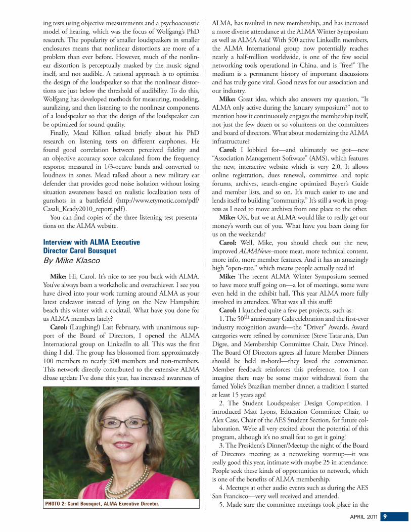
Interview with ALMA Executive Director Carol Bousquet
By Mike Klasco
Mike: Hi, Carol. It’s nice to see you back with ALMA. You’ve always been a workaholic and overachiever. I see you have dived into your work turning around ALMA as your latest endeavor instead of lying on the New Hampshire beach this winter with a cocktail. What have you done for us ALMA members lately?
Carol: (Laughing!) Last February, with unanimous sup-port of the Board of Directors, I opened the ALMA International group on LinkedIn to all. This was the first thing I did. The group has blossomed from approximately 100 members to nearly 500 members and non-members. This network directly contributed to the extensive ALMA dbase update I’ve done this year, has increased awareness of
ALMA, has resulted in new membership, and has increased a more diverse attendance at the ALMA Winter Symposium as well as ALMA Asia! With 500 active LinkedIn members, the ALMA International group now potentially reaches nearly a half-million worldwide, is one of the few social networking tools operational in China, and is “free!” The medium is a permanent history of important discussions and has truly gone viral. Good news for our association and our industry.
Mike: Great idea, which also answers my question, “Is ALMA only active during the January symposium?” not to mention how it continuously engages the membership itself, not just the few dozen or so volunteers on the committees and board of directors. What about modernizing the ALMA infrastructure?
Carol: I lobbied for—and ultimately we got—new “Association Management Software” (AMS), which features the new, interactive website which is very 2.0. It allows online registration, dues renewal, committee and topic forums, archives, search-engine optimized Buyer’s Guide and member lists, and so on. It’s much easier to use and lends itself to building “community.” It’s still a work in prog-ress as I need to move archives from one place to the other.
Mike: OK, but we at ALMA would like to really get our money’s worth out of you. What have you been doing for us on the weekends?
Carol: Well, Mike, you should check out the new, improved ALMANews–more meat, more technical content, more info, more member features. And it has an amazingly high “open-rate,” which means people actually read it!
Mike: The recent ALMA Winter Symposium seemed to have more stuff going on—a lot of meetings, some were even held in the exhibit hall. This year ALMA more fully involved its attendees. What was all this stuff?
Carol: I launched quite a few pet projects, such as:1. The 50th anniversary Gala celebration and the first-ever
industry recognition awards—the “Driver” Awards. Award categories were refined by committee (Steve Tatarunis, Dan Digre, and Membership Committee Chair, Dave Prince). The Board Of Directors agrees all future Member Dinners should be held in-hotel—they loved the convenience. Member feedback reinforces this preference, too. I can imagine there may be some major withdrawal from the famed Yolie’s Brazilian member dinner, a tradition I started at least 15 years ago!
2. The Student Loudspeaker Design Competition. I introduced Matt Lyons, Education Committee Chair, to Alex Case, Chair of the AES Student Section, for future col-laboration. We’re all very excited about the potential of this program, although it’s no small feat to get it going!
3. The President’s Dinner/Meetup the night of the Board of Directors meeting as a networking warmup—it was really good this year, intimate with maybe 25 in attendance. People seek these kinds of opportunities to network, which is one of the benefits of ALMA membership.
4. Meetups at other audio events such as during the AES San Francisco—very well received and attended.
5. Made sure the committee meetings took place in the PHOTO 2: Carol Bousquet, ALMA Executive Director.
10 VOICE COIL
exhibit area—committee chairs were ecstatic about atten-dance and participation versus people having to leave the excitement of the exhibit area and go to a dark meeting room halfway to Timbuktu. This really worked!
6. And, as important as any of the above, the new contract with Job Target to create an online Job Board for the loud-speaker industry on the ALMA website—debuting this Spring.
Mike: You have reached out to other organizations and media—and seem to have some results. . .
Carol: The whole graphical corporate image of ALMA underwent a makeover and redesign this year that has worked to generate excitement and enthusiasm and has resulted in new membership and attendance at the sym-posia. Additionally, thanks to a generous sponsorship by Voice Coil, I was able to include a full-page two-sided Winter Symposium insert/invitation in the October AES edition. We supplemented that distribution during the San Francisco AES by having them in ALMA-AES member booths as well as handed them out. We also distributed custom invitations specifically to the AES-ALMA Meetup. It’s classical marketing stuff.
Mike: The CEA, the group that owns the CES show, is a large industry organization and lobby. From the interaction with CEA representatives at the ALMA Board meeting, my impression is that we are not big enough to get even the few crumbs ALMA needs. You were staffing the ALMA booth on the CES floor thanks to an affiliated association relation-ship (one of the tidbits CEA offers to us) at the entrance to the North Hall during CES. You were also hanging out in the IEEE-CE Division booth—are you dating anyone there? By the way, I joined the IEEE when I was in gradu-ate school (in the early 1970s) and it is a great organiza-tion. They offer everything from student grants to health insurance programs for its membership. The IEEE audio group (IEEE transactions on audio and electroacoustics) faded into the consumer electronics group and AES became the forum for this stuff. And the IEEE is strong enough to wrestle space and attention from the CEA.
Carol: As a result of the conversations I had with the folks there, I’ve been thinking how this is an important discussion to pursue for sure. I expect it will be part of our Spring Strategic Planning Meeting—which, by the way, is open to members, not just the Board of Directors. At the CES show the IEEE people insisted they’d welcome us not for the cash (however, they have deep pockets and could help ALMA along financially and in many other ways, I’m sure) but for the intelligence sharing. It seems to me, at first glance, obvious. Everyone I’ve discussed this with lights up like a lantern and are IEEE members already or have had a positive experience with them over time and know how impactful they can be. Think of ALMA loudspeaker stan-dards and so on. . .
Mike: Finally, I would like to mention that Carol sug-gested her goal in life is to be nominated for a Driver Award herself. Having worked with Carol on various ALMA endeavors, from my heart, I suggest Carol have the honor of a special award—the ALMA Slave Driver Award! VC
APRIL 2011 11
Test Bench
Wavecor and Beyma Home and Pro DriversBy Vance Dickason
�his month’s Test Bench driver submissions came from Wavecor and Beyma, representing high-end home
audio drivers and high-power pro audio drivers. From Wavecor I received a 7″ paper cone midwoofer, the WF182BD04-1, and from Beyma, a new 12″ neo sub-woofer, the 12SW1300Nd.
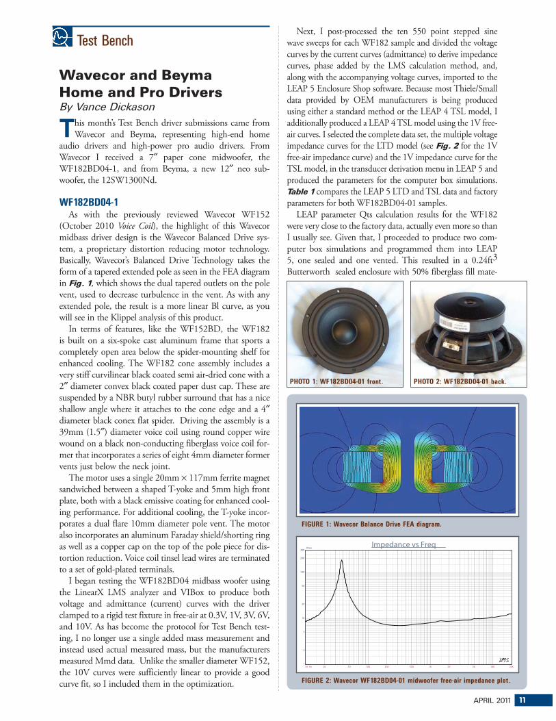
WF182BD04-1As with the previously reviewed Wavecor WF152
(October 2010 Voice Coil), the highlight of this Wavecor midbass driver design is the Wavecor Balanced Drive sys-tem, a proprietary distortion reducing motor technology. Basically, Wavecor’s Balanced Drive Technology takes the form of a tapered extended pole as seen in the FEA diagram in Fig. 1, which shows the dual tapered outlets on the pole vent, used to decrease turbulence in the vent. As with any extended pole, the result is a more linear Bl curve, as you will see in the Klippel analysis of this product.
In terms of features, like the WF152BD, the WF182 is built on a six-spoke cast aluminum frame that sports a completely open area below the spider-mounting shelf for enhanced cooling. The WF182 cone assembly includes a very stiff curvilinear black coated semi air-dried cone with a 2″ diameter convex black coated paper dust cap. These are suspended by a NBR butyl rubber surround that has a nice shallow angle where it attaches to the cone edge and a 4″ diameter black conex flat spider. Driving the assembly is a 39mm (1.5″) diameter voice coil using round copper wire wound on a black non-conducting fiberglass voice coil for-mer that incorporates a series of eight 4mm diameter former vents just below the neck joint.
The motor uses a single 20mm × 117mm ferrite magnet sandwiched between a shaped T-yoke and 5mm high front plate, both with a black emissive coating for enhanced cool-ing performance. For additional cooling, the T-yoke incor-porates a dual flare 10mm diameter pole vent. The motor also incorporates an aluminum Faraday shield/shorting ring as well as a copper cap on the top of the pole piece for dis-tortion reduction. Voice coil tinsel lead wires are terminated to a set of gold-plated terminals.
I began testing the WF182BD04 midbass woofer using the LinearX LMS analyzer and VIBox to produce both voltage and admittance (current) curves with the driver clamped to a rigid test fixture in free-air at 0.3V, 1V, 3V, 6V, and 10V. As has become the protocol for Test Bench test-ing, I no longer use a single added mass measurement and instead used actual measured mass, but the manufacturers measured Mmd data. Unlike the smaller diameter WF152, the 10V curves were sufficiently linear to provide a good curve fit, so I included them in the optimization.
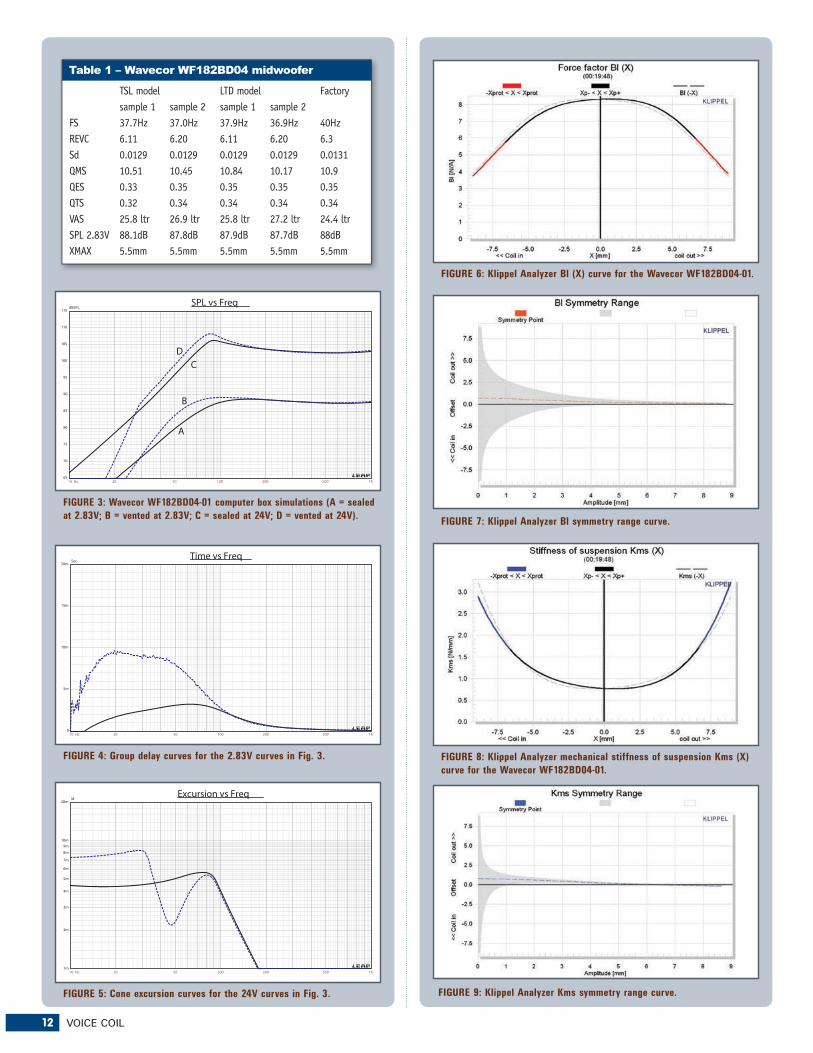
Next, I post-processed the ten 550 point stepped sine wave sweeps for each WF182 sample and divided the voltage curves by the current curves (admittance) to derive impedance curves, phase added by the LMS calculation method, and, along with the accompanying voltage curves, imported to the LEAP 5 Enclosure Shop software. Because most Thiele/Small data provided by OEM manufacturers is being produced using either a standard method or the LEAP 4 TSL model, I additionally produced a LEAP 4 TSL model using the 1V free-air curves. I selected the complete data set, the multiple voltage impedance curves for the LTD model (see Fig. 2 for the 1V free-air impedance curve) and the 1V impedance curve for the TSL model, in the transducer derivation menu in LEAP 5 and produced the parameters for the computer box simulations. Table 1 compares the LEAP 5 LTD and TSL data and factory parameters for both WF182BD04-01 samples.
LEAP parameter Qts calculation results for the WF182 were very close to the factory data, actually even more so than I usually see. Given that, I proceeded to produce two com-puter box simulations and programmed them into LEAP 5, one sealed and one vented. This resulted in a 0.24ft3 Butterworth sealed enclosure with 50% fiberglass fill mate-
FIGURE 9: Klippel Analyzer Kms symmetry range curve.
APRIL 2011 13
rial, and a 0.37ft3 vented QB3 alignment enclosure simula-tion with 15% fiberglass fill material and tuned to 44Hz.
Figure 3 displays the results for the WF182BD04 in the sealed and vented boxes at 2.83V and at a voltage level high enough to increase cone excursion to Xmax + 15% (5.75mm). This produced a F3 frequency of 77Hz with a box/driver Qtc of 0.68 for the 0.24ft3 sealed enclosure and –3dB = 44Hz for the 0.37ft3 vented QB3 simulation. Increasing the volt-age input to the simulations until the maximum linear cone excursion was reached resulted in 106dB at 24V for the sealed enclosure simulation and 108dB with the same 24V input level for the larger ported enclosure (see Figs. 4 and 5 for the 2.83V group delay curves and the 24V excursion curves). Note that excursion begins increasing below 35Hz, so a high-pass filter below this frequency would greatly increase the power handling, which is the case for most vented designs.
Klippel analysis for the Wavecor 7″ woofer (our analyzer is provided courtesy of Klippel GmbH), performed by Pat Turnmire, Red Rock Acoustics (author of the SpeaD and RevSpeaD software) produced the Bl(X), Kms(X) and Bl and Kms symmetry range plots given in Figs. 6-9. The Bl(X) curve for the WF182 (Fig. 6) is relatively broad and nicely sym-metrical. The Bl symmetry plot curve (Fig. 7) shows a trivial 0.69mm coil forward offset at the rest position that decreases to 0.2mm at the physical 5.5mm Xmax of the driver, so this driver looks very well balanced. Figures 8 and 9 show the Kms(X) and Kms symmetry range curves for the Wavecor midbass woof-er. The Kms(X) curve is also very symmetrical, and has a very minor forward (coil-out) offset of 0.76mm at the rest position that decreases to 0.17mm at the 5.5mm physical Xmax location on the graph, which is likewise trivial. Displacement limiting numbers calculated by the Klippel analyzer for the WF182 were XBl at 82% Bl = 5.5mm, and for XC at 75% Cms minimum was 3.9mm, which means that the compliance is the most limit-ing factor for prescribed distortion level of 10%.
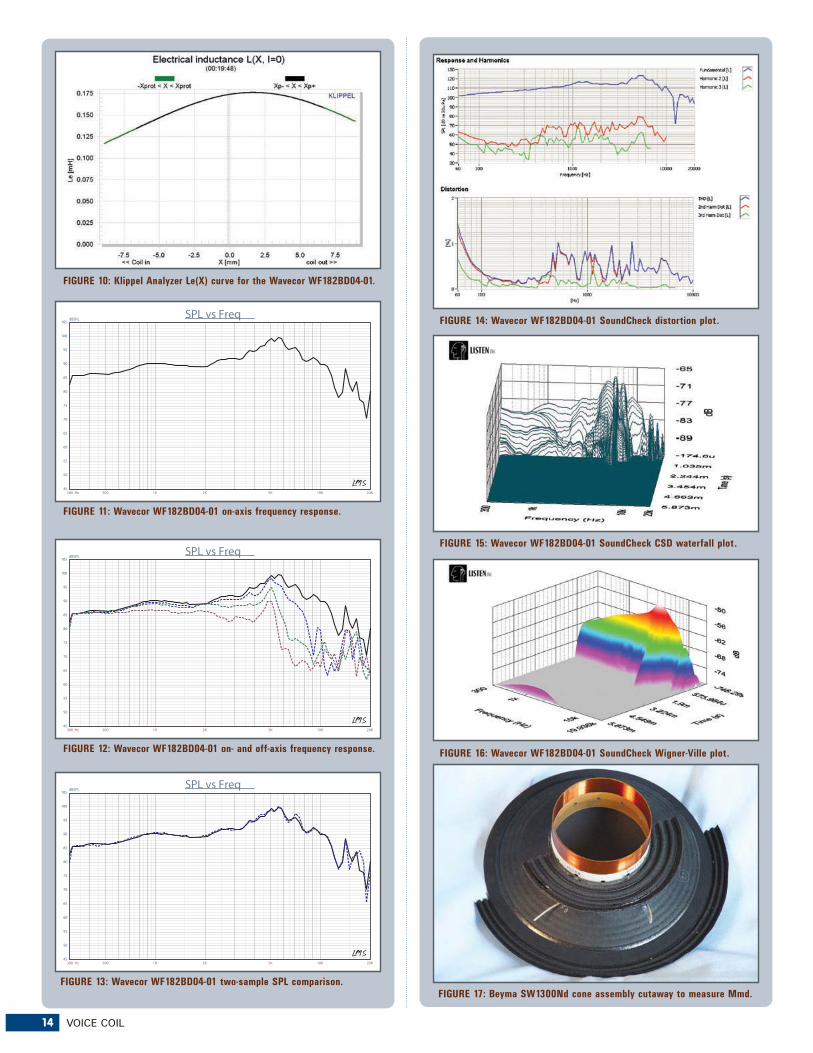
Figure 10 displays the inductance curve Le(X) for the WF182BD04-01. Inductance will typically increase in the rear direction from the zero rest position as the voice coil covers more pole area. However, the WF182 inductance shows only minor inductive variation as the coil moves in both directions due to the dual shorting ring configuration. The inductance variation is only a maximum of 0.03mH from the rest position to the full in and out Xmax positions, which is very good.
Next I mounted the WF182 woofer in an enclosure which had an 18″ × 8″ baffle and was filled with damping material (foam) and then measured the DUT on- and off-axis from 300Hz to 40kHz frequency response at 2.83V/1m using the LinearX LMS analyzer set to a 100-point gated sine wave sweep. Figure 11 gives the WF182’s on-axis response indicating a very smoothly rising response to about 5.5kHz, with no peaking at the high-pass rolloff. Figure 12 displays the on- and off-axis frequency response at 0, 15, 30, and 45°. -3dB at 30° off-axis with respect to the on-axis curve occurs at 3.0kHz, so a crossover in the 3kHz region would be appropriate. And, finally, Fig. 13 gives the two-sample SPL comparisons for the 7″ Wavecor midbass, showing a close match to less than 0.5dB throughout the operating range.
For the remaining battery of tests, I employed the Listen
14 VOICE COIL
300 Hz 500 1K 2K 5K 10K 20K
dBSPL
45
50
55
60
65
70
75
80
85
90
95
100
105SPL vs Freq
300 Hz 500 1K 2K 5K 10K 20K
dBSPL
45
50
55
60
65
70
75
80
85
90
95
100
105SPL vs Freq
300 Hz 500 1K 2K 5K 10K 20K
dBSPL
45
50
55
60
65
70
75
80
85
90
95
100
105SPL vs Freq
FIGURE 10: Klippel Analyzer Le(X) curve for the Wavecor WF182BD04-01.
FIGURE 11: Wavecor WF182BD04-01 on-axis frequency response.
FIGURE 12: Wavecor WF182BD04-01 on- and off-axis frequency response.
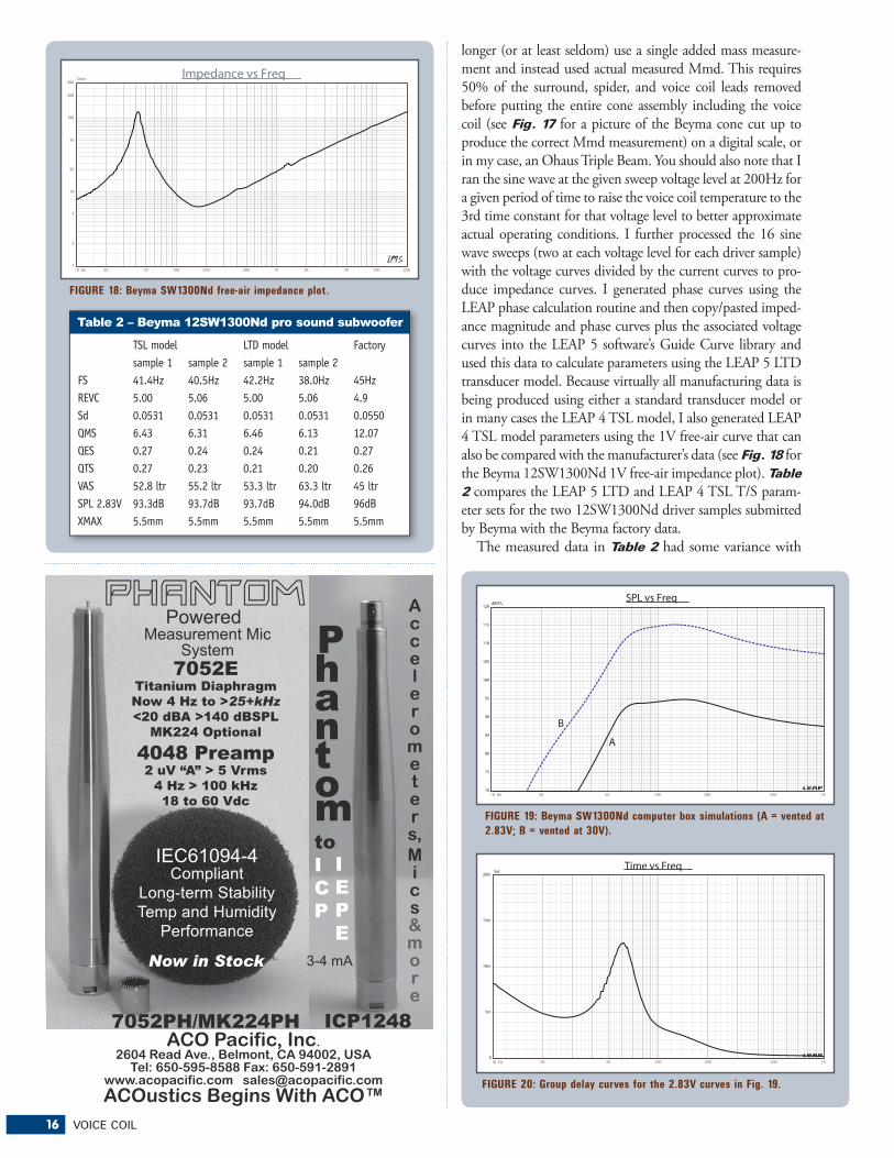
FIGURE 17: Beyma SW1300Nd cone assembly cutaway to measure Mmd.
APRIL 2011 15
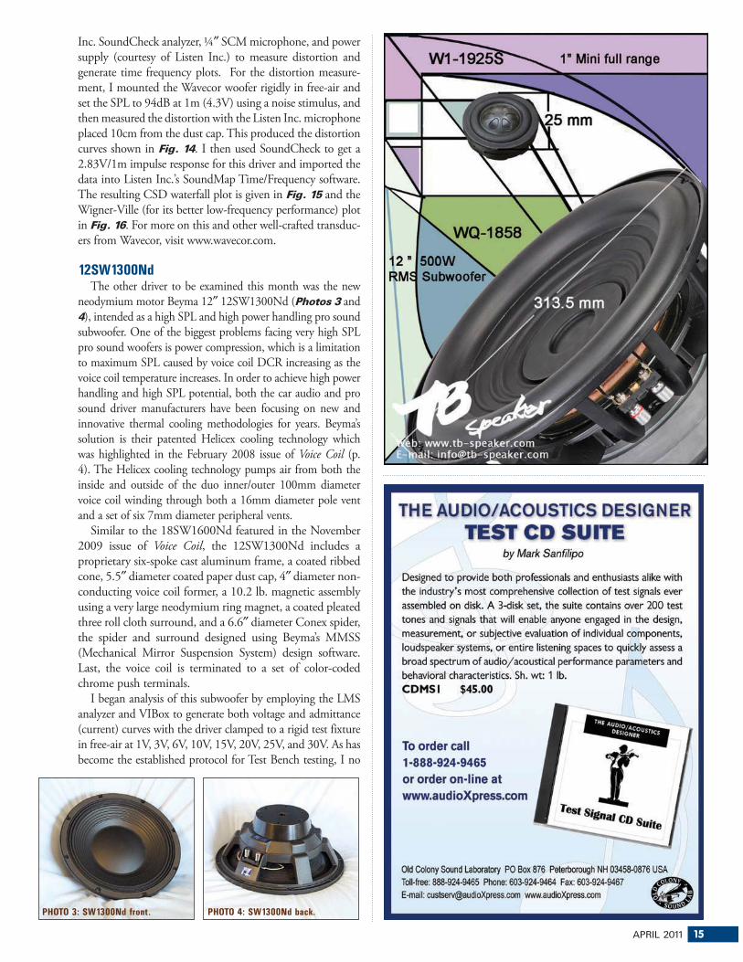
Inc. SoundCheck analyzer, ¼″ SCM microphone, and power supply (courtesy of Listen Inc.) to measure distortion and generate time frequency plots. For the distortion measure-ment, I mounted the Wavecor woofer rigidly in free-air and set the SPL to 94dB at 1m (4.3V) using a noise stimulus, and then measured the distortion with the Listen Inc. microphone placed 10cm from the dust cap. This produced the distortion curves shown in Fig. 14. I then used SoundCheck to get a 2.83V/1m impulse response for this driver and imported the data into Listen Inc.’s SoundMap Time/Frequency software. The resulting CSD waterfall plot is given in Fig. 15 and the Wigner-Ville (for its better low-frequency performance) plot in Fig. 16. For more on this and other well-crafted transduc-ers from Wavecor, visit www.wavecor.com.
12SW1300NdThe other driver to be examined this month was the new
neodymium motor Beyma 12″ 12SW1300Nd (Photos 3 and 4), intended as a high SPL and high power handling pro sound subwoofer. One of the biggest problems facing very high SPL pro sound woofers is power compression, which is a limitation to maximum SPL caused by voice coil DCR increasing as the voice coil temperature increases. In order to achieve high power handling and high SPL potential, both the car audio and pro sound driver manufacturers have been focusing on new and innovative thermal cooling methodologies for years. Beyma’s solution is their patented Helicex cooling technology which was highlighted in the February 2008 issue of Voice Coil (p. 4). The Helicex cooling technology pumps air from both the inside and outside of the duo inner/outer 100mm diameter voice coil winding through both a 16mm diameter pole vent and a set of six 7mm diameter peripheral vents.
Similar to the 18SW1600Nd featured in the November 2009 issue of Voice Coil, the 12SW1300Nd includes a proprietary six-spoke cast aluminum frame, a coated ribbed cone, 5.5″ diameter coated paper dust cap, 4″ diameter non-conducting voice coil former, a 10.2 lb. magnetic assembly using a very large neodymium ring magnet, a coated pleated three roll cloth surround, and a 6.6″ diameter Conex spider, the spider and surround designed using Beyma’s MMSS (Mechanical Mirror Suspension System) design software. Last, the voice coil is terminated to a set of color-coded chrome push terminals.
I began analysis of this subwoofer by employing the LMS analyzer and VIBox to generate both voltage and admittance (current) curves with the driver clamped to a rigid test fixture in free-air at 1V, 3V, 6V, 10V, 15V, 20V, 25V, and 30V. As has become the established protocol for Test Bench testing, I no
PHOTO 3: SW1300Nd front. PHOTO 4: SW1300Nd back.
16 VOICE COIL
longer (or at least seldom) use a single added mass measure-ment and instead used actual measured Mmd. This requires 50% of the surround, spider, and voice coil leads removed before putting the entire cone assembly including the voice coil (see Fig. 17 for a picture of the Beyma cone cut up to produce the correct Mmd measurement) on a digital scale, or in my case, an Ohaus Triple Beam. You should also note that I ran the sine wave at the given sweep voltage level at 200Hz for a given period of time to raise the voice coil temperature to the 3rd time constant for that voltage level to better approximate actual operating conditions. I further processed the 16 sine wave sweeps (two at each voltage level for each driver sample) with the voltage curves divided by the current curves to pro-duce impedance curves. I generated phase curves using the LEAP phase calculation routine and then copy/pasted imped-ance magnitude and phase curves plus the associated voltage curves into the LEAP 5 software’s Guide Curve library and used this data to calculate parameters using the LEAP 5 LTD transducer model. Because virtually all manufacturing data is being produced using either a standard transducer model or in many cases the LEAP 4 TSL model, I also generated LEAP 4 TSL model parameters using the 1V free-air curve that can also be compared with the manufacturer’s data (see Fig. 18 for the Beyma 12SW1300Nd 1V free-air impedance plot). Table 2 compares the LEAP 5 LTD and LEAP 4 TSL T/S param-eter sets for the two 12SW1300Nd driver samples submitted by Beyma with the Beyma factory data.
The measured data in Table 2 had some variance with
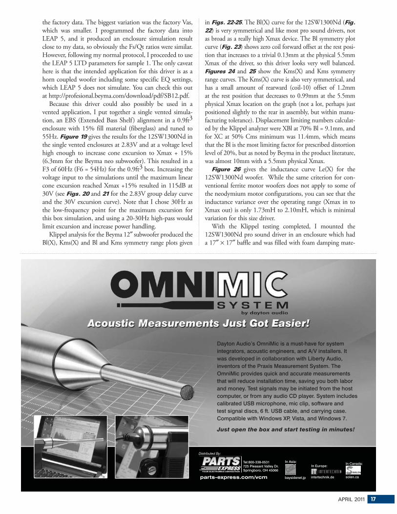
FIGURE 20: Group delay curves for the 2.83V curves in Fig. 19.
APRIL 2011 17
the factory data. The biggest variation was the factory Vas, which was smaller. I programmed the factory data into LEAP 5, and it produced an enclosure simulation result close to my data, so obviously the Fs/Qt ratios were similar. However, following my normal protocol, I proceeded to use the LEAP 5 LTD parameters for sample 1. The only caveat here is that the intended application for this driver is as a horn coupled woofer including some specific EQ settings, which LEAP 5 does not simulate. You can check this out at http://profesional.beyma.com/download/pdf/SB12.pdf.
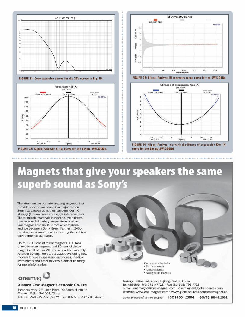
Because this driver could also possibly be used in a vented application, I put together a single vented simula-tion, an EBS (Extended Bass Shelf ) alignment in a 0.9ft3 enclosure with 15% fill material (fiberglass) and tuned to 55Hz. Figure 19 gives the results for the 12SW1300Nd in the single vented enclosures at 2.83V and at a voltage level high enough to increase cone excursion to Xmax + 15% (6.3mm for the Beyma neo subwoofer). This resulted in a F3 of 60Hz (F6 = 54Hz) for the 0.9ft3 box. Increasing the voltage input to the simulations until the maximum linear cone excursion reached Xmax +15% resulted in 115dB at 30V (see Figs. 20 and 21 for the 2.83V group delay curve and the 30V excursion curve). Note that I chose 30Hz as the low-frequency point for the maximum excursion for this box simulation, and using a 20-30Hz high-pass would limit excursion and increase power handling.
Klippel analysis for the Beyma 12″ subwoofer produced the Bl(X), Kms(X) and Bl and Kms symmetry range plots given
in Figs. 22-25. The Bl(X) curve for the 12SW1300Nd (Fig. 22) is very symmetrical and like most pro sound drivers, not as broad as a really high Xmax device. The Bl symmetry plot curve (Fig. 23) shows zero coil forward offset at the rest posi-tion that increases to a trivial 0.13mm at the physical 5.5mm Xmax of the driver, so this driver looks very well balanced. Figures 24 and 25 show the Kms(X) and Kms symmetry range curves. The Kms(X) curve is also very symmetrical, and has a small amount of rearward (coil-10) offset of 1.2mm at the rest position that decreases to 0.99mm at the 5.5mm physical Xmax location on the graph (not a lot, perhaps just positioned slightly to the rear in assembly, but within manu-facturing tolerance). Displacement limiting numbers calculat-ed by the Klippel analyzer were XBl at 70% Bl = 9.1mm, and for XC at 50% Cms minimum was 11.4mm, which means that the Bl is the most limiting factor for prescribed distortion level of 20%, but as noted by Beyma in the product literature, was almost 10mm with a 5.5mm physical Xmax.
Figure 26 gives the inductance curve Le(X) for the 12SW1300Nd woofer. While the same criterion for con-ventional ferrite motor woofers does not apply to some of the neodymium motor configurations, you can see that the inductance variance over the operating range (Xmax in to Xmax out) is only 1.73mH to 2.10mH, which is minimal variation for this size driver.
With the Klippel testing completed, I mounted the 12SW1300Nd pro sound driver in an enclosure which had a 17″ × 17″ baffle and was filled with foam damping mate-
Just open the box and start testing in minutes!
Dayton Audio’s OmniMic is a must-have for system
integrators, acoustic engineers, and A/V installers. It
was developed in collaboration with Liberty Audio,
inventors of the Praxis Measurement System. The
OmniMic provides quick and accurate measurements
that will reduce installation time, saving you both labor
and money. Test signals may be initiated from the host
computer, or from any audio CD player. System includes
calibrated USB microphone, mic clip, software and
test signal discs, 6 ft. USB cable, and carrying case.
Compatible with Windows XP, Vista, and Windows 7.
Distributed By:
Tel:800-338-0531725 Pleasant Valley Dr.Springboro, OH 45066
In Europe:
intertechnik.de
In Asia:
baysidenet.jp
In Canada:
solen.caparts-express.com/vcm
18 VOICE COIL
10 Hz 20 50 100 200 500 1K
M
1m
2m
3m
4m
5m
6m
7m
8m
9m
10m
20m
Excursion vs Freq
FIGURE 22: Klippel Analyzer Bl (X) curve for the Beyma SW1300Nd.
FIGURE 24: Klippel Analyzer mechanical stiffness of suspension Kms (X)
curve for the Beyma SW1300Nd.
FIGURE 21: Cone excursion curves for the 30V curves in Fig. 19. FIGURE 23: Klippel Analyzer Bl symmetry range curve for the SW1300Nd.
APRIL 2011 19
300 Hz 500 1K 2K 5K 10K 20K
dBSPL
45
50
55
60
65
70
75
80
85
90
95
100
105SPL vs Freq
FIGURE 26: Klippel Analyzer Le(X) curve for the Beyma SW1300Nd.
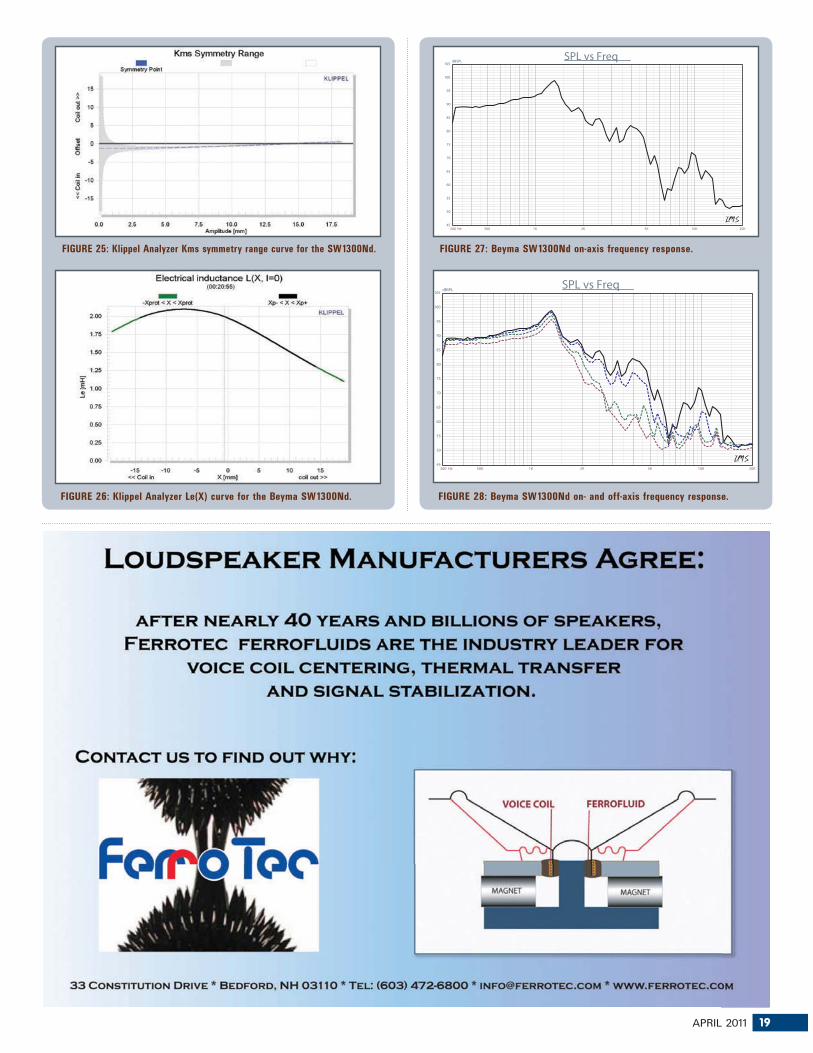
FIGURE 25: Klippel Analyzer Kms symmetry range curve for the SW1300Nd. FIGURE 27: Beyma SW1300Nd on-axis frequency response.
300 Hz 500 1K 2K 5K 10K 20K
dBSPL
45
50
55
60
65
70
75
80
85
90
95
100
105SPL vs Freq
FIGURE 28: Beyma SW1300Nd on- and off-axis frequency response.
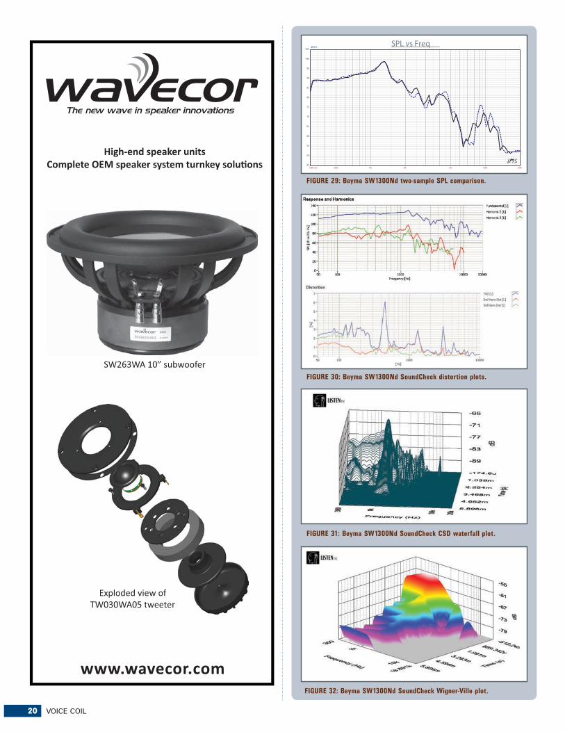
rial and then measured the driver both on- and off-axis from 300Hz to 20kHz frequency response at 2.83V/1m using a 100-point gated sine wave sweep. Figure 27 depicts the on-axis response that is a smooth even response up to cone breakup peak at 1.3kHz followed by the low-pass rolloff. Figure 28 illustrates the on- and off-axis frequency response at 0, 15, 30, and 45°. Even though this is a subwoofer, it would be possible to use it in a two-way or three-way con-figuration with a vented box. In the suggested Beyma horn load application, it would just be a subwoofer. And last, Fig. 29 gives the two-sample SPL comparisons for the 12″ Beyma driver, showing a good match throughout the operating range of this woofer. Of course, if you are using it as a sub in a short coupled horn enclosure, this really isn’t important.
For the last body of testing on the Beyma 12″, I again fired up the Listen Inc. SoundCheck analyzer and SCM microphone and power supply to measure distortion and generate time frequency plots. Setting up for the distortion measurement again consisted of mounting the woofer rigidly in free-air, and setting the SPL to 104dB at 1m (14.8V) using a noise stimulus (SoundCheck has a software generator and SPL meter as two of its utilities). I then measured the distortion with the SCM microphone placed 10cm from the dust cap, which produced the distortion curves in Fig. 30.
For the last test on the 12SW1300Nd, I used the SoundCheck analyzer to get a 2.83V/1m impulse response for this driver and imported the data into Listen Inc.’s SoundMap Time/Frequency software. The resulting CSD waterfall plot is given in Fig. 31 and the Wigner-Ville (for its better low-frequency performance) plot in Fig. 32. For more information on this well-executed neo 12″ driver and other Beyma pro sound products, visit www.beyma.com. VC
Sample Submission for Test BenchTest Bench is an open forum for OEM driver manufacturers in the industry and all OEMs are invited to submit samples to Voice Coil for inclusion in the monthly Test Bench column. Driver samples can be for use in any sector of the loudspeaker market including transducers for home audio, car audio, pro sound, multimedia, or musical instrument applications. While many of the drivers featured in Voice Coil come from OEMs that have a stable catalog of product, this is not a necessary criterion for submission. OEM manufacturers are encouraged to send samples of woofers, midranges, or tweeters they think are representative of their work. However, please contact Voice Coil Editor Vance Dickason prior to submission to discuss which drivers are being submitted. Samples should be sent in pairs and addressed to:
Vance Dickason Consulting333 S. State St., #152Lake Oswego, OR 97034(503-557-0427)[email protected] samples must include any published data on the prod-
uct, patent information, or any special information necessary to explain the functioning of the transducer. This should include details regarding the various materials used to construct the transducer such as cone material, voice coil former material, and voice coil wire type. For woofers and midrange drivers, please include the voice coil height, gap height, RMS power handling, and physically measured Mmd (complete cone assembly including the cone, surround, spider, and voice coil with 50% of the spider, surround, and lead wires removed).
22 VOICE COIL
Acoustic Patents By James Croft
�he following loudspeaker-related patents were filed primarily under the Office of Patent and Trademarks
classification 181 for acoustical devices and 381 for electri-cal-signal processing systems and HO4R for international patents. This also includes new patent applications that are published in the Patent Application Journal.
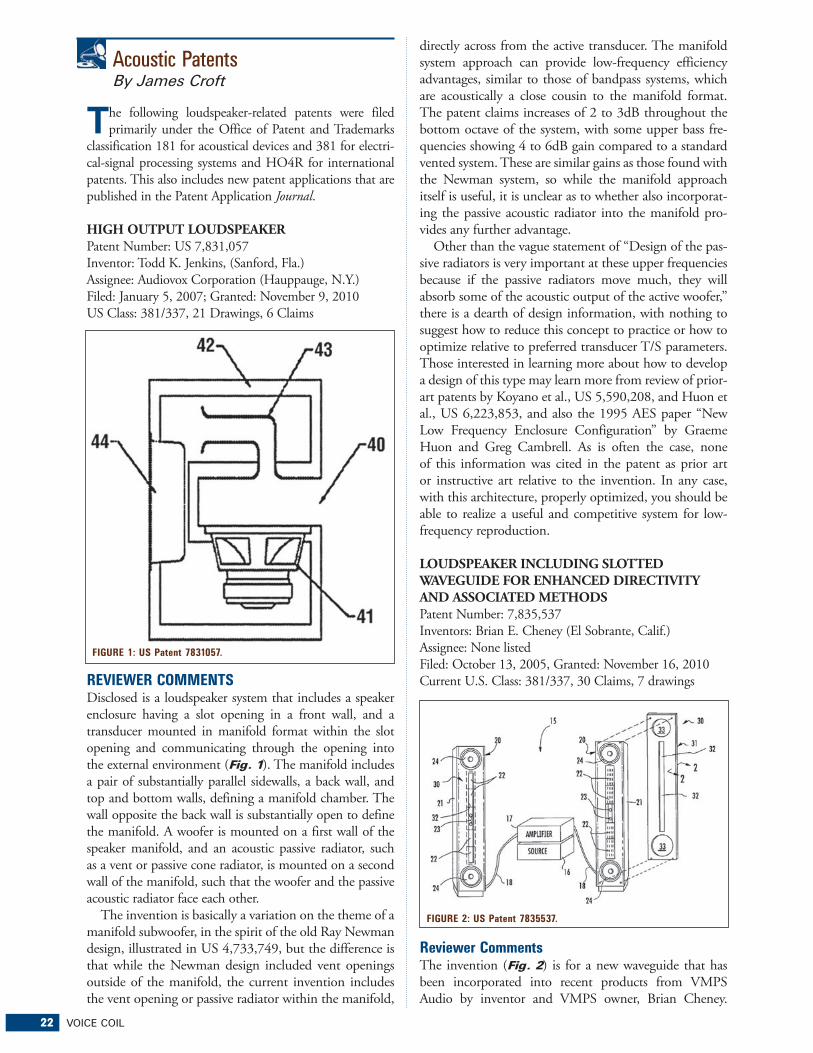
HIGH OUTPUT LOUDSPEAKERPatent Number: US 7,831,057Inventor: Todd K. Jenkins, (Sanford, Fla.)Assignee: Audiovox Corporation (Hauppauge, N.Y.)Filed: January 5, 2007; Granted: November 9, 2010US Class: 381/337, 21 Drawings, 6 Claims
REVIEWER COMMENTS Disclosed is a loudspeaker system that includes a speaker enclosure having a slot opening in a front wall, and a transducer mounted in manifold format within the slot opening and communicating through the opening into the external environment (Fig. 1). The manifold includes a pair of substantially parallel sidewalls, a back wall, and top and bottom walls, defining a manifold chamber. The wall opposite the back wall is substantially open to define the manifold. A woofer is mounted on a first wall of the speaker manifold, and an acoustic passive radiator, such as a vent or passive cone radiator, is mounted on a second wall of the manifold, such that the woofer and the passive acoustic radiator face each other.
The invention is basically a variation on the theme of a manifold subwoofer, in the spirit of the old Ray Newman design, illustrated in US 4,733,749, but the difference is that while the Newman design included vent openings outside of the manifold, the current invention includes the vent opening or passive radiator within the manifold,
directly across from the active transducer. The manifold system approach can provide low-frequency efficiency advantages, similar to those of bandpass systems, which are acoustically a close cousin to the manifold format. The patent claims increases of 2 to 3dB throughout the bottom octave of the system, with some upper bass fre-quencies showing 4 to 6dB gain compared to a standard vented system. These are similar gains as those found with the Newman system, so while the manifold approach itself is useful, it is unclear as to whether also incorporat-ing the passive acoustic radiator into the manifold pro-vides any further advantage.
Other than the vague statement of “Design of the pas-sive radiators is very important at these upper frequencies because if the passive radiators move much, they will absorb some of the acoustic output of the active woofer,” there is a dearth of design information, with nothing to suggest how to reduce this concept to practice or how to optimize relative to preferred transducer T/S parameters. Those interested in learning more about how to develop a design of this type may learn more from review of prior-art patents by Koyano et al., US 5,590,208, and Huon et al., US 6,223,853, and also the 1995 AES paper “New Low Frequency Enclosure Configuration” by Graeme Huon and Greg Cambrell. As is often the case, none of this information was cited in the patent as prior art or instructive art relative to the invention. In any case, with this architecture, properly optimized, you should be able to realize a useful and competitive system for low-frequency reproduction.
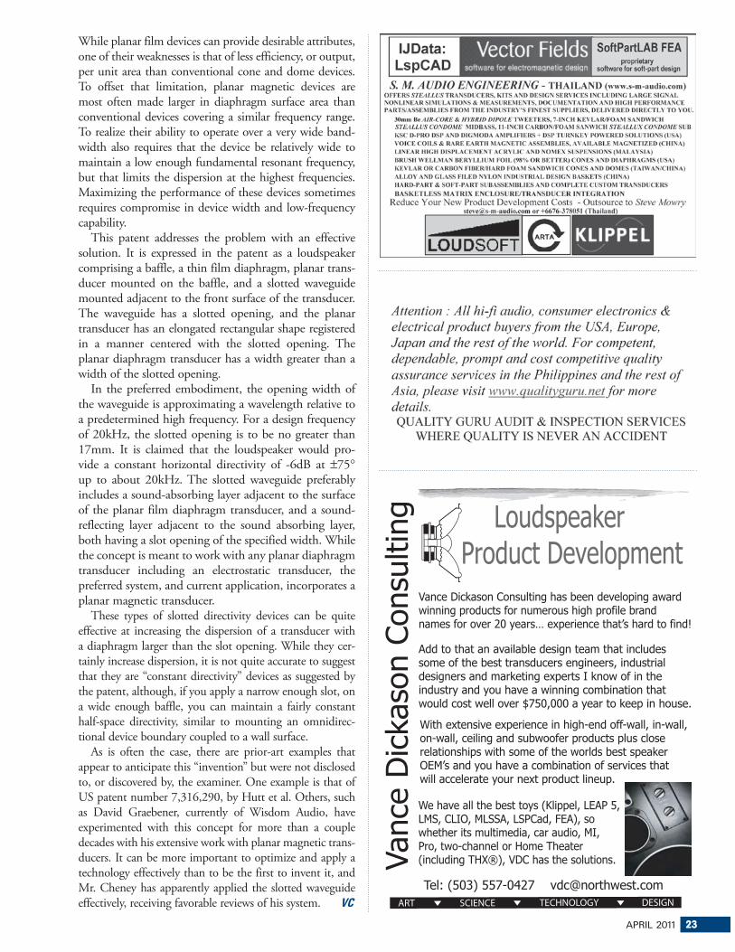
LOUDSPEAKER INCLUDING SLOTTED WAVEGUIDE FOR ENHANCED DIRECTIVITY AND ASSOCIATED METHODSPatent Number: 7,835,537Inventors: Brian E. Cheney (El Sobrante, Calif.)Assignee: None listedFiled: October 13, 2005, Granted: November 16, 2010Current U.S. Class: 381/337, 30 Claims, 7 drawings
Reviewer CommentsThe invention (Fig. 2) is for a new waveguide that has been incorporated into recent products from VMPS Audio by inventor and VMPS owner, Brian Cheney.
FIGURE 1: US Patent 7831057.
FIGURE 2: US Patent 7835537.
APRIL 2011 23
While planar film devices can provide desirable attributes, one of their weaknesses is that of less efficiency, or output, per unit area than conventional cone and dome devices. To offset that limitation, planar magnetic devices are most often made larger in diaphragm surface area than conventional devices covering a similar frequency range. To realize their ability to operate over a very wide band-width also requires that the device be relatively wide to maintain a low enough fundamental resonant frequency, but that limits the dispersion at the highest frequencies. Maximizing the performance of these devices sometimes requires compromise in device width and low-frequency capability.
This patent addresses the problem with an effective solution. It is expressed in the patent as a loudspeaker comprising a baffle, a thin film diaphragm, planar trans-ducer mounted on the baffle, and a slotted waveguide mounted adjacent to the front surface of the transducer. The waveguide has a slotted opening, and the planar transducer has an elongated rectangular shape registered in a manner centered with the slotted opening. The planar diaphragm transducer has a width greater than a width of the slotted opening.
In the preferred embodiment, the opening width of the waveguide is approximating a wavelength relative to a predetermined high frequency. For a design frequency of 20kHz, the slotted opening is to be no greater than 17mm. It is claimed that the loudspeaker would pro-vide a constant horizontal directivity of -6dB at ±75°up to about 20kHz. The slotted waveguide preferably includes a sound-absorbing layer adjacent to the surface of the planar film diaphragm transducer, and a sound-reflecting layer adjacent to the sound absorbing layer, both having a slot opening of the specified width. While the concept is meant to work with any planar diaphragm transducer including an electrostatic transducer, the preferred system, and current application, incorporates a planar magnetic transducer.
These types of slotted directivity devices can be quite effective at increasing the dispersion of a transducer with a diaphragm larger than the slot opening. While they cer-tainly increase dispersion, it is not quite accurate to suggest that they are “constant directivity” devices as suggested by the patent, although, if you apply a narrow enough slot, on a wide enough baffle, you can maintain a fairly constant half-space directivity, similar to mounting an omnidirec-tional device boundary coupled to a wall surface.
As is often the case, there are prior-art examples that appear to anticipate this “invention” but were not disclosed to, or discovered by, the examiner. One example is that of US patent number 7,316,290, by Hutt et al. Others, such as David Graebener, currently of Wisdom Audio, have experimented with this concept for more than a couple decades with his extensive work with planar magnetic trans-ducers. It can be more important to optimize and apply a technology effectively than to be the first to invent it, and Mr. Cheney has apparently applied the slotted waveguide effectively, receiving favorable reviews of his system. VC
�udiovox (www.audiovox.com) and Klipsch Group (www.klipsch.com)
entered into a definitive agreement in which Audiovox will buy Klipsch for $166 million. Klipsch will become a wholly owned subsidiary of Audiovox, will be run as a standalone operation in Indianapolis, and will continue to be led by Klipsch’s current management team. Audiovox expects to finance the acquisition with a combination of exist-ing Audiovox cash and a new asset-based revolving credit facility that will also be used for operating capital. Once the deal closes, Audiovox also expects to have money left over under the credit facility for general corporate purposes. On a pro-forma basis, for the 12 months ending Nov. 30, 2010, the combined companies’ revenues were about $742.2 million, compared with $573.1 million for Audiovox as a standalone company.
Ultimate Acquisition Partners, the parent company of the 46-store A/V and appliance chain (www.ultimateelectron-ics.com), has filed for Chapter 11 bankruptcy protection in Delaware. In the filing, CEO Bruce Giesbrecht said the action was prompted by “a significant downturn in business” at some Ultimate Electronics locations and the refusal of certain ven-dors to ship products on open credit. The company, which is 71% held by chairman Mark Wattles’ investment firm, Wattles Capital Management, and 25% held by Hewlett-Packard, is seeking to use cash collateral to continue day-to-day operations and pay its vendors. Many of the chain’s vendors have agreed to reopen their credit lines once their payables are paid.
Top unsecured creditors include New Age Electronics/Synnex ($5.5 million), Sony Electronics ($4.8 million), GE Money Bank ($3 million), and Monster ($2.3 million). Manufacturers owed between $1 million and $2 million include, in descending order, Klipsch, Mitsubishi, Toshiba, Haier, and Whirlpool. The company has accounts receivable of about $2 million, inventory valued at $98 million, and real estate holdings valued at $12.8 million. Liabilities are between $100 million and $500 million, court documents show. This is the second filing for Ultimate Electronics in six years. Wattles, the founder of Hollywood Video and a dissi-dent Circuit City shareholder, bought a controlling interest in the chain in 2005, filed Chapter 11, and reacquired the business in a bankruptcy auction later that year. Since then Wattles built the Colorado-based company from 32 to 46 stores, including some in distant markets in the Northeast, and added new categories to its core A/V mix, including major appliances and billiard tables.
Rockford Corp. (www.rockfordcorp.com) appointed its VP sales and marketing Bill Jackson to the position of president while Gary Suttle, formerly president and CEO, remains CEO. The company said Jackson’s appointment will allow Suttle to focus on Rockford’s strategic direc-
tion as it completes its transformation from a manufacturing-focused company to a “designer, marketer and distribu-tor” of car audio aftermarket and OEM products. Jackson will assume primary responsibility for Rockford’s worldwide, day-to-day operations, the company said. He will be replaced by Michael Chass, VP Automotive OEM for D & M Holdings (the holding company for Denon, Marantz, Boston Acoustics, and other companies), who will assume the title of VP sales. Jackson joined Rockford in 1995 as a regional sales manager and held a variety of sales management posi-tions until he was named VP of sales and marketing in February 2004. Prior to joining Rockford, he managed a retail
consumer electronics store for 13 years and operated a manu-facturer’s sales representative firm for three years.
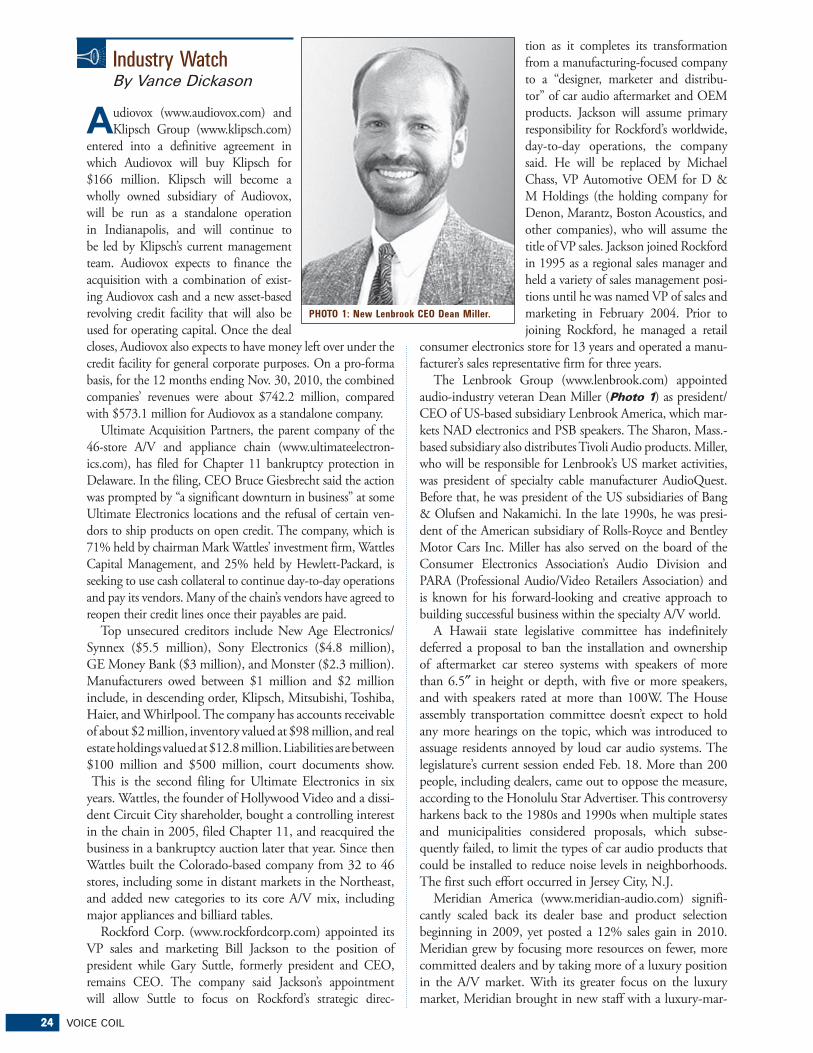
The Lenbrook Group (www.lenbrook.com) appointed audio-industry veteran Dean Miller (Photo 1) as president/CEO of US-based subsidiary Lenbrook America, which mar-kets NAD electronics and PSB speakers. The Sharon, Mass.-based subsidiary also distributes Tivoli Audio products. Miller, who will be responsible for Lenbrook’s US market activities, was president of specialty cable manufacturer AudioQuest. Before that, he was president of the US subsidiaries of Bang & Olufsen and Nakamichi. In the late 1990s, he was presi-dent of the American subsidiary of Rolls-Royce and Bentley Motor Cars Inc. Miller has also served on the board of the Consumer Electronics Association’s Audio Division and PARA (Professional Audio/Video Retailers Association) and is known for his forward-looking and creative approach to building successful business within the specialty A/V world.
A Hawaii state legislative committee has indefinitely deferred a proposal to ban the installation and ownership of aftermarket car stereo systems with speakers of more than 6.5″ in height or depth, with five or more speakers, and with speakers rated at more than 100W. The House assembly transportation committee doesn’t expect to hold any more hearings on the topic, which was introduced to assuage residents annoyed by loud car audio systems. The legislature’s current session ended Feb. 18. More than 200 people, including dealers, came out to oppose the measure, according to the Honolulu Star Advertiser. This controversy harkens back to the 1980s and 1990s when multiple states and municipalities considered proposals, which subse-quently failed, to limit the types of car audio products that could be installed to reduce noise levels in neighborhoods. The first such effort occurred in Jersey City, N.J.
Meridian America (www.meridian-audio.com) signifi-cantly scaled back its dealer base and product selection beginning in 2009, yet posted a 12% sales gain in 2010. Meridian grew by focusing more resources on fewer, more committed dealers and by taking more of a luxury position in the A/V market. With its greater focus on the luxury market, Meridian brought in new staff with a luxury-mar-
PHOTO 1: New Lenbrook CEO Dean Miller.
APRIL 2011 25
ket background and opened up its US headquarters here for use as a dealer showroom to demonstrate Meridian’s high-end audio and video products to high-level business execu-tives, athletes, and actors who don’t shop in retail stores. Meridian also began to support dealers whose high-profile customers want a demo in their own homes. For these dealers, Meridian flies out products and staff to set up and demo a system in the potential customer’s home and let the homeowner live with it for a day. About 90% of the time, Meridian staff makes the presentation to the consumer, but the dealer sets up the appointment and profits from the sale. All home demos to date have closed a sale.
The reduction in the US dealer base began in late 2009, and by the end of 2010, the company had reduced its 250 active accounts to 150. By mid February, the company had pared more dealers, bringing the base to 120. And more cuts could be coming. To reinforce its luxury position, a Meridian-branded autosound system will appear globally this May in the Range Rover Evoque. The Meridian brand already appears on sound systems in McLaren vehicles.
In paring its selection, the company reduced its SKU count to 30 from as many as 130 in 2007. The company, however, is gearing up to add at least one more product, a six-zone Sooloos audio server that offers more zones and more output types per zone compared to the company’s other multizone servers. The MediaCore 600 will be Meridian’s first multizone server with proprietary SpeakerLink output. Although many specs haven’t been finalized, the server will
feature one analog output, one coaxial digital output, and one SpeakerLink output per zone.
SpeakerLink delivers balanced 96kHz/24-bit digital audio and control signals up to 300′ over CAT-5e RJ-45-terminated cable to the company’s active DSP speakers, including its active in-wall DSP speakers. SpeakerLink eliminates signal losses and coloration induced by analog signals riding on a cable, and it simplifies cable connections because Meridian DSP speakers can be daisy-chained to avoid home-running cable from each speaker to a Meridian component.
Harman International’s consumer division posted world-wide operating income of $11 million in its fiscal second quar-
26 VOICE COIL
ter (www.harman.com). This was up sequentially from zero operating income in the first quarter and up 91% from the $6 million posted a year ago. The division’s income gain came on net sales growth in the second quarter of 10% to $139 million, up sequentially from a 3% gain in the previous quarter and up 10% from the year-ago quarter. For the half, net sales were up
7% to $226 million. Consumer division gross profit also rose in the quarter and half, with second-quarter gross profit rising 19% to $42 million, and second-half gross profit hitting $67 million, up 16% from the year-ago $57 million.
On a consolidated basis that includes the automotive OEM and professional-audio divisions, Harman posted gains in net sales, operating income, and net income in its fiscal second quarter and first half, marking the company’s fifth consecutive quarterly net profit. Growth in sales and operating income came in the professional-audio segment in the quarter and half ending December 2010. Operating income in the automotive OEM segment rose in the quar-ter and half, but automotive sales dipped 1% in the quarter while rising in the half by 5%. Consolidated sales in all three segments were up 3% to $956 million in the quarter and up 7% in the half to $1.79 billion. Consolidated operating income was up 82% to $68 million for the quarter and almost quadrupled for the half to $111 million. Net income from continuing operations almost tripled to $53 million in the quarter from a year-ago $13.4 million and shot way up to $80.4 million for the half from a year-ago $1.82 million.
Consumer confidence in the overall economy reached its highest level in nearly three years this month, according to the latest figures released by the Consumer Electronics Association (CEA). The CEA Indexes also show consumer confidence in technology reached an all-time high for the month of January.
For the sixth consecutive month, consumer confidence in the overall direction of the economy improved. The CEA
PHOTO 2: One of Kicker’s new OEM car audio speakers.
PHOTO 3: The Harman-Kardon sound bar.
APRIL 2011 27
��������™ R & D Measurement system
�������������
Features: Multiple displays of min. 16 responses
Cumulative decay spectrum “Waterfall”
THD + 2 – 9th harmonics distortion
1/12 - 1/6 - 1/3 – 1/2 – 1/1 octave
Anechoic FFT - Acoustic auto-delay
50 curves/responses/TS parameters
SPL/Frequency, Imp., phase, export
Soundcards: PCI/USB/Firewire/ASIO
Headsets, USB/Bluetooth
Index of Consumer Expectations (ICE) rose one point in January to 175.7. That’s the highest the ICE has been since February 2008. The ICE, which measures consumer expec-tations about the broader economy, is up more than nine points from this time last year.
Consumer confidence in technology is the highest it’s ever been in the month of January, despite dropping from last month’s record high. The CEA Index of Consumer Technology Expectations (ICTE) fell 5.6 points to 88.1 this month. The ICTE, which measures consumer expectations about technol-ogy spending, still recorded its highest level ever for the month of January and is up more than four points from this time last year. The CEA Indexes comprise the ICE and ICTE, both of which are updated on a monthly basis through consumer surveys. New data is released on the fourth Tuesday of each month. CEA has been tracking index data since January 2007. To find current and past indexes, charts, methodology, and future release dates, log on to CEAindexes.org.
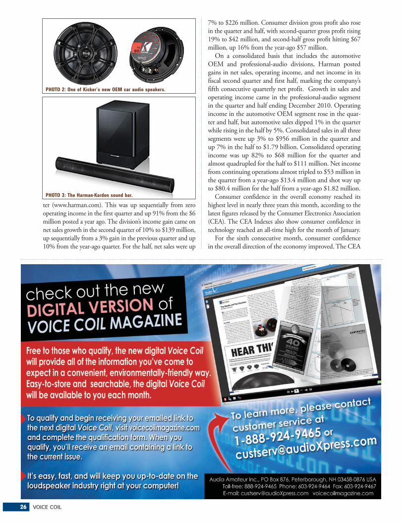
Stillwater Designs has begun shipping its Kicker-brand KS series of coaxial and three-way car speakers designed for drop-in replacement of factory speakers (www.kicker.com). The updated series of ten models, priced from a suggested $59.95 to $179.95/pair, features larger magnet/motor struc-tures than the predecessor series to handle more power, be more efficient, and thus play louder and with greater accu-racy, a spokesman said. The models (Photo 2) also feature proprietary Extended Voice Coil technology to deliver high excursion and thus deeper bass response. The series starts with 3.5″ coaxial and tops out with a 6 × 9″ three-way model with 1″ midrange and 0.75″ tweeter. Sizes include 3.5, 4, 4 × 10, 5.25, 6, 6.5, 6 × 8, and 6 × 9″ models.
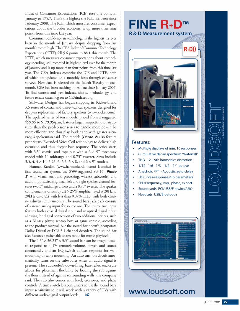
Harman Kardon (www.harmankardon.com) launched its first sound bar system, the $599-suggested SB 16 (Photo 3) with virtual surround processing, wireless subwoofer, and audio-input switching. Each left and right speaker channel fea-tures two 3″ midrange drivers and a 0.75″ tweeter. The speaker complement is driven by a 2 × 25W amplifier rated at 20Hz to 20kHz onto 8Ω with less than 0.07% THD with both chan-nels driven simultaneously. The sound bar’s jack pack consists of a stereo analog input for source one. The source two input features both a coaxial digital input and an optical digital input, allowing for digital connection of two additional devices, such as a Blu-ray player, set-top box, or game console, according to the product manual, but the sound bar doesn’t incorporate Dolby Digital or DTS 5.1-channel decoders. The sound bar also features a switchable stereo mode for music playback.
The 4.3″ × 36.25″ × 3.5″ sound bar can be programmed to respond to a TV remote’s volume, power, and source commands, and an EQ switch adjusts response for wall mounting or table mounting. An auto turn-on circuit auto-matically turns on the subwoofer when an audio signal is present. The subwoofer’s down-firing bass-reflex enclosure allows for placement flexibility by loading the sub against the floor instead of against surrounding walls, the company said. The sub also comes with level, crossover, and phase controls. A trim switch lets consumers adjust the sound bar’s input sensitivity so it will work with a variety of TVs with different audio-signal output levels. VC
28 VOICE COIL
Product News
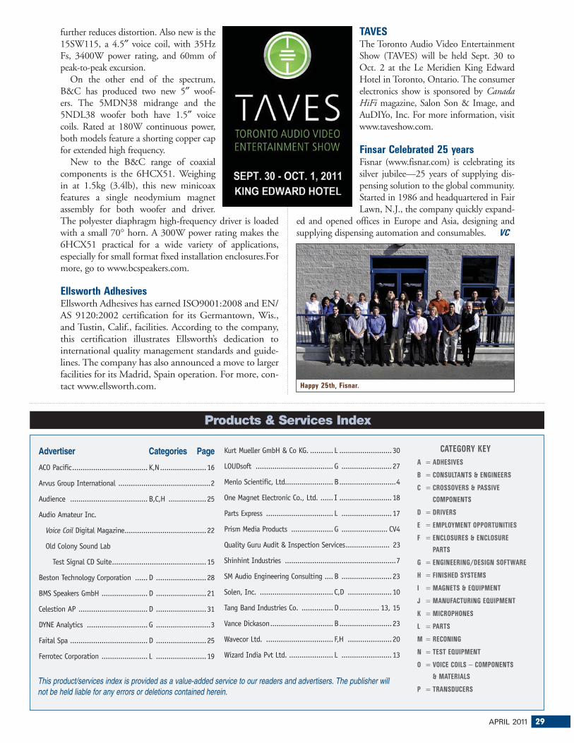
Jensen Falcon 10″Jensen® Musical Instrument Speakers’ latest addition to the Jensen® Jet series is the 10″ Falcon. With its 40W of power, a ceramic magnet, and a seamed green cone made from all natural materials, the 10″ Falcon is specially designed to ensure optimum tone for all styles of music.
The Falcon 10″ tone is warm and straightforward with a pronounced low end. According to the company, its mid frequencies are slightly enhanced over the Falcon 12″, and it has a very sweet, yet cutting, high end. When presented with overdrive distortion it produces some mean fuzz. For more, go to jensentone.com.
New from B&CB&C’s high-performance “SW Series” subwoofer fam-ily has two new 15″ members. The 15SW100 4″ voice coil subwoofer is a 3,000W neodymium motor driver that incorporates B&C’s split winding voice coil technol-ogy, which dramatically reduces distortion and nonlinear-ity. And peak-to-peak excursion is 57mm. Other features include a ventilated voice coil gap for reduced power compression, and an aluminum demodulation ring that
Wizard India Pvt Ltd. ..................... L ........................13
CATEGORY KEY
A = ADHESIVES
B = CONSULTANTS & ENGINEERS
C = CROSSOVERS & PASSIVE
COMPONENTS
D = DRIVERS
E = EMPLOYMENT OPPORTUNITIES
F = ENCLOSURES & ENCLOSURE
PARTS
G = ENGINEERING/DESIGN SOFTWARE
H = FINISHED SYSTEMS
I = MAGNETS & EQUIPMENT
J = MANUFACTURING EQUIPMENT
K = MICROPHONES
L = PARTS
M = RECONING
N = TEST EQUIPMENT
O = VOICE COILS − COMPONENTS
& MATERIALS
P = TRANSDUCERSThis product/services index is provided as a value-added service to our readers and advertisers. The publisher will not be held liable for any errors or deletions contained herein.
Products & Services Index
further reduces distortion. Also new is the 15SW115, a 4.5″ voice coil, with 35Hz Fs, 3400W power rating, and 60mm of peak-to-peak excursion.
On the other end of the spectrum, B&C has produced two new 5″ woof-ers. The 5MDN38 midrange and the 5NDL38 woofer both have 1.5″ voice coils. Rated at 180W continuous power, both models feature a shorting copper cap for extended high frequency.
New to the B&C range of coaxial components is the 6HCX51. Weighing in at 1.5kg (3.4lb), this new minicoax features a single neodymium magnet assembly for both woofer and driver. The polyester diaphragm high-frequency driver is loaded with a small 70° horn. A 300W power rating makes the 6HCX51 practical for a wide variety of applications, especially for small format fixed installation enclosures.For more, go to www.bcspeakers.com.
Ellsworth Adhesives Ellsworth Adhesives has earned ISO9001:2008 and EN/AS 9120:2002 certification for its Germantown, Wis., and Tustin, Calif., facilities. According to the company, this certification illustrates Ellsworth’s dedication to international quality management standards and guide-lines. The company has also announced a move to larger facilities for its Madrid, Spain operation. For more, con-tact www.ellsworth.com.
TAVESThe Toronto Audio Video Entertainment Show (TAVES) will be held Sept. 30 to Oct. 2 at the Le Meridien King Edward Hotel in Toronto, Ontario. The consumer electronics show is sponsored by Canada HiFi magazine, Salon Son & Image, and AuDIYo, Inc. For more information, visit www.taveshow.com.
Finsar Celebrated 25 yearsFisnar (www.fisnar.com) is celebrating its silver jubilee—25 years of supplying dis-pensing solution to the global community. Started in 1986 and headquartered in Fair Lawn, N.J., the company quickly expand-
ed and opened offices in Europe and Asia, designing and supplying dispensing automation and consumables. VC
Innovative drivers Custom development services Global operations
���������������������������
-�+./0-+ "-12
�����������������������������
For more information on Celestion's comprehensive range of professional audio productsincluding CDX compression drivers, visit the Celestion Professional website:
...integrated
electronic test, acoustic test...
Prism Sound is now a globalsales & support agent for: