IN THIS ISSUE VOLUME 27, ISSUE 1 NOVEMBER 2012 29 INDUSTRY NEWS & DEVELOPMENTS By Vance Dickason 1 SPOTLIGHT Time Synchronous Averaging By Chris Struck TEST BENCH Pro Sound Coax from B&C and a New Professional Series 15” from Eminence By Vance Dickason INDUSTRY WATCH By Vance Dickason Industry News & Developments Happy 26 th Anniversary, Voice Coil November 2012 marks the beginning of Voice Coil’s 26 th year as an information resource for the loudspeaker industry. Voice Coil magazine resulted from a conversation I had with Ed Dell following Audio Amateur’s publication of the Loudspeaker Design Cookbook, 3 rd edition. Ed related his concept to cre- ate a publication that would become the loudspeaker inddustry’s “information super highway.” Needless to say, I considered it not only an outstanding concept for a new publication, but something I felt the indus- try badly needed and that I would happily support. Obviously, after 26 years, we were right to move for- ward with the publication. Ed came up with the Voice Coil name, and as they say, the rest is history. From the first issue in November 1987 until June 1995, Voice Coil was a monthly subscription-based, black-and-white, four-page newsletter I wrote with no additional contributors and no advertising. However, the June 1995 issue jumped to 20 pages of four-color printing on glossy paper. (Voice Coil is currently 32 to 48 pages each month!) The magazine is now advertiser driven, and it is free for qualified subscribers. With the era of digital delivery, Voice Coil became available as an Internet- delivered subscription in 2012. Besides the change in printing, distribution, and digital delivery, Voice Coil began to include other contributors (e.g., Jim Croft, Charlie Hughes, Mike Klasco, Wolfgang Klippel, Steve Mowry, Steve Temme, Pat Turnmire, and many others over the years). Support has come from some of the industry’s finest engineers, and through the gen- erosity of analyzer/software manufacturers (e.g., Klippel, LinearX, and Listen) which have supplied Voice Coil with some of the best test equipment available. As the loudspeaker industry magazine grows and matures, Voice Coil has stayed true to its original con- cept, a world-class clearinghouse of information for loud- speaker engineers, manufacturers, marketing specialists, and OEM suppliers. Evidenced by the participation of writers, advertisers, and readers, Voice Coil continues to be well received by the entire loudspeaker industry. Each By Vance Dickason 5 SPOTLIGHT AES “Classics” Series Closed-Box Loudspeaker with a Series Capacitor By Neville Thiele ACOUSTIC PATENTS By James Croft 9 14 PRODUCTS & SERVICES 16 17
Transcript
IN THIS ISSUE
V O L U M E 2 7 , I S S U E 1 N O V E M B E R 2 0 1 2
29
INDUSTRY NEWS & DEVELOPMENTSBy Vance Dickason
1 SPOTLIGHTTime Synchronous AveragingBy Chris Struck
TEST BENCH Pro Sound Coax from B&C and a New Professional Series 15” from EminenceBy Vance Dickason
INDUSTRY WATCH By Vance Dickason
Industry News & Developments
Happy 26th Anniversary, Voice CoilNovember 2012 marks the beginning of Voice
Coil’s 26th year as an information resource for the loudspeaker industry. Voice Coil magazine resulted from a conversation I had with Ed Dell following Audio Amateur’s publication of the Loudspeaker Design Cookbook, 3rd edition. Ed related his concept to cre-ate a publication that would become the loudspeaker inddustry’s “information super highway.” Needless to say, I considered it not only an outstanding concept for a new publication, but something I felt the indus-try badly needed and that I would happily support. Obviously, after 26 years, we were right to move for-ward with the publication. Ed came up with the Voice Coil name, and as they say, the rest is history.
From the first issue in November 1987 until June 1995, Voice Coil was a monthly subscription-based, black-and-white, four-page newsletter I wrote with no additional contributors and no advertising. However, the
June 1995 issue jumped to 20 pages of four-color printing on glossy paper. (Voice Coil is currently 32 to 48 pages each month!) The magazine is now advertiser driven, and it is free for qualified subscribers. With the era of digital delivery, Voice Coil became available as an Internet-delivered subscription in 2012.
Besides the change in printing, distribution, and digital delivery, Voice Coil began to include other contributors (e.g., Jim Croft, Charlie Hughes, Mike Klasco, Wolfgang Klippel, Steve Mowry, Steve Temme, Pat Turnmire, and many others over the years). Support has come from some of the industry’s finest engineers, and through the gen-erosity of analyzer/software manufacturers (e.g., Klippel, LinearX, and Listen) which have supplied Voice Coil with some of the best test equipment available.
As the loudspeaker industry magazine grows and matures, Voice Coil has stayed true to its original con-cept, a world-class clearinghouse of information for loud-speaker engineers, manufacturers, marketing specialists, and OEM suppliers. Evidenced by the participation of writers, advertisers, and readers, Voice Coil continues to be well received by the entire loudspeaker industry. Each
By Vance Dickason
5SPOTLIGHTAES “Classics” SeriesClosed-Box Loudspeaker with a Series CapacitorBy Neville Thiele
Voice Coil, (ISSN 1521-091X), The Periodical for the Loudspeaker Industry, is published monthly by Segment, LLC, 4 Park St., Vernon, CT 06066 USA, (860) 875-2199, FAX (860) 871-0411. Periodical postage paid at Vernon, CT and additional offices.
Head Office: Segment LLC4 Park St., Vernon, CT 06066Phone: (860) 875-2199
Subscriptions: Subscriptions to Voice Coil are available in printed and digital versions. To subscribe, please visit our website at www.audioamateur.com and complete a qualification form. Qualified subscriptions to Voice Coil run for one year. Renew annually on-line at www.audioamateur.com
Postmaster: Send address changes to Voice Coil Circulation Dept., P.O. Box 462256, Escondido, CA 92046.
When you qualify, you will receive an e-mail confirming your subscription. The current issue of each digital Voice Coil will be posted to www.gotomyvcoil.com at the end of the month. To access, use the link in the e-mail notification, or you can simply log in to the website to view your issue along with the archived issues.
For those overseas, the cost of a printed subscription is $150.00 per year. Please contact customer service or order your subscription online at www.audioamateur.com.
THE WORLD’S SOURCE FOR EMBEDDED ELECTRONICS ENGINEERING INFORMATION
Tech the Future explores the solutions for a sustainable future provided by technology, creativity and science.
Not a member yet?Subscribe at www.audioamateur.com
U.S. Advertising: Strategic Media Marketing, Inc.2 Main St., Gloucester, MA 01930 USAPhone: (978) 281-7708Fax: (978) 281-7706, e-mail: [email protected]
Advertising rates and terms available on request. E-mail Erica Fienman with artwork inquiries at: [email protected].
Editorial Inquiries:Send all press releases and information to Voice Coil, Segment, LLC Editorial Dept., 4 Park St., Vernon, CT 06066, or FAX us material at (860) 871-0411, or e-mail [email protected].
Legal Notice:Copyright 2012 by Segment, LLC. All rights reserved. Quotation from Voice Coil is forbidden without written permission of the publisher.Printed in the United States
Not a supporting company yet? Contact Peter Wostrel ([email protected], Phone (978) 281-7708, Fax (978) 281-7706)
to reserve your own space for the next issue of our member magazine
M = RECONINGN = TEST EQUIPMENTO = VOICE COILS − COMPONENTS & MATERIALSP = TRANSDUCERSQ = ACOUSTIC MESHR = ACOUSTICAL & SOUNDPROOFING MATERIALSAMPLIFICATIONT = TRADE SHOWU = HEADSETSV = AMPLIFICATIONW = DIGITAL SIGNAL PROCESSING
CATEGORY KEY
274283 83We now have
members in countries.
6 VOICE COIL
year brings increased circulation as more engineers, techni-cians, purchasing agents, and marketing experts discover what we offer. On behalf of Vance Dickason, editor; Hugo Van haecke, publisher; C. J. Abate, editorial coordinator; Shannon Becker, editorial assistant; and all the staff at Audio Amateur who make this publication possible, we would like to thank our readers and advertisers for their continued enthusiasm and support.
ALMA Symposium 2013The Association of Loudspeaker Manufacturing & Acoustics
International (ALMA) Winter Symposium, the world’s largest event entirely dedicated to the loudspeaker industry, features training courses on modeling, measurement, and manufactur-ing in today’s multinational, cooperative environment. There will be technical paper presentations, tutorial sessions, round table and panel discussions, an exhibit hall showcasing indus-try suppliers, and an annual banquet where the now famous “Driver Awards” are presented to deserving recipients.
The Winter Symposium banquet keynote presentation will feature “The Life & Times of Paul Klipsch.” Jim Hunter, pro-gram manager and Klipsch historian, is a 34-year veteran at Klipsch. He has amassed an incredible documentary of Paul Klipsch, whose fifth career in life was audio. Jim will present a slide show presentation that includes archival documents and photos going back to 1978! He has at least 5,000 scans from which to choose. The presentation will include a mention of technical papers at General Electric in 1927 and the Chilean
Nitrate Mining Co. from 1928 and 1929. Jim admitted it is difficult to separate the man from the company; how-ever, we can trace the industry’s development from Edwin Armstrong demoing FM with Klipschorn, to the New York Audio Fair, to correspondence and visits with John Eargle, Sherman Fairchild, Arthur Fiedler, Avery Fisher, Dick Heyser, Saul Marantz, and more.
The ALMA Winter Symposium, “Product Development in the Global Paradigm: Acoustic Modeling, Measurement and Manufacturing in the Modern Marketplace” will be held January 6 and 7, 2013, at The Tuscany Suites & Casino, 255 East Flamingo Road, Las Vegas, NV. The program will cover technology such as microdrivers, microphones, hearing aids, and other transducer-related technology. The 2013 International CES immediately follows the sympo-sium, January 8–11, 2013.
The symposium program features two powerful half-day seminars taught by two widely respected loudspeaker experts: “Moving Coil Transducer Motor Design,” facilitated by Richard Little, founder of Far North Electroacoustics and “Miniature Speakers and Microphones: Design and Application,” facilitated by Osman Isvan, a renowned inven-tor and audio systems engineer.
Little’s seminar will cover the design of moving coil trans-ducers’ magnetic motors, which can cause design engineers to encounter many different issues and choices. The semi-nar will review motor design topics including: objectives, magnet material types and grades, typical magnetic motor
NOVEMBER 2012 7
design topologies, the permanent magnet magnetization process, thermal demagnetization, voice coil design, design options, voice coil inductance, the analysis of motor design through physical equations, and through finite element anal-ysis, methods for measuring magnetic motor performance, and the general topic of nonlinear motor behavior. Case studies and examples will illustrate and illuminate the topics.
Isvan’s seminar will explore omnidirectional and noise-canceling microphones. Surface-mount technology (SMT), electrically commuted motors (ECM), microelectromechani-cal systems (MEMS), and digital and analog microphone technology will be discussed. Handheld devices’ special operating conditions and constraints make microspeaker design a unique discipline. Headphone drivers require special test methods due to their unique acoustic coupling. Two-way communication environments introduce additional param-eters. Audio digital signal processing (DSP) shuffles acoustic design priorities. High-component density leads to unwanted interactions, and microphones’ super-miniaturization make signal-to-noise ratio (SNR) targets more challenging to meet. All this and more will be discussed with examples. Visit www.almainternational.org for more information and to register, exhibit, or sponsor the symposium.
InfoComm/NSCA NewsInfoComm International announced future scheduling plans
for its annual InfoComm exposition and conference. The show will rotate between locations every mid-June through 2019.
InfoComm 2013 will be held at Orlando’s Orange County Convention Center’s West Building, Orlando, FL, June 12–14. InfoComm 2014 will be held at Las Vegas Convention Center’s North and Central Halls, Las Vegas, NV, June 18–20. InfoComm has signed lease agreements with both facilities.
Also, the National Systems Contractors Association (NSCA) has reconfirmed its commitment to InfoComm. Although the NSCA and InfoComm contract under its current arrangement has expired, NSCA will continue its support of the InfoComm show moving forward. NSCA will be present on the show floor and host the NSCA Education Foundation Industry Charity Concert featuring the Drunk Unkles in 2013. In addition to its continued presence at the InfoComm show, NSCA will provide more frequent educational opportunities at smaller venues and events to capital-ize on emerging markets, such as Mass Notification and Emergency Communication (MNEC) systems; keep its members apprised of policies and regulations; and build business and management skills to help integrators grow and prosper.
Also of interest is the new NSCA MNEC website. This web-site focuses on the use of commercial speakers’ intelligibility in buildings. The website also provides information on the issue’s history, codes and standards, articles on the subject, and more about this relatively new and growing market. While the intelligibility for these systems mostly deals with placement, the intelligibility of the PA speakers is also an issue. Visit www.mnec.org for more information.
8 VOICE COIL
New Loctite Brochure & WebsiteHenkel has introduced two new resources that provide
detailed information about the company’s Loctite Instant Adhesives line and present the latest innovations in cya-noacrylate technology. “Instant Solutions in Every Drop” is a 16-page brochure that reviews the company’s compre-hensive Loctite Instant Adhesives line, including the most recent product innovations, including grades that resist temperatures to 250°F, low-odor/low-bloom products that resist elevated temperatures and maintain strength in high-humidity environments, and a grade specifically formulated to fill gaps as deep as 5 mm.
The literature also highlights dispensing and curing equipment and provides information on Henkel technical and engineering support services. A newly designed web-site provides up-to-the-minute product information, real-world applications, videos/demonstrations, and dispensing and curing solutions.
Instant adhesives are one-part, room-temperature cur-ing adhesives available in a variety of viscosities. With fixture speeds measured in seconds, they provide excellent adhesion to most substrates and can be used in automated assembly applications. Recent technological advances in surface insensitivity, flexibility, and temperature resistance have made these adhesives a trusted solution for an ever-widening array of products and applications.
To download a brochure or to review the new Loctite Instant Adhesives website, visit www.instantsolutions.loctite.com. VC
- Custom coils available in: Multi-layer wire configurations Multiple lead configurations Round and Flat Wire Custom lead-out attachments
- High temperature adhesive coated Copper and Aluminum wire in round and flat sizes. CCAW wire available in round sizes.
- Adhesive coated custom cut forms and Collars.
- Custom slit rolls of Form and Collar material available coated or uncoated.
8940 North Fork Drive, North Fort Myers, Florida 33903Phone (239) 997-3860 Fax (239) 997-3243
For samples, information, or a quotation, please contact Jon Van Rhee at [email protected]
Visit us on the web at www.precisioneconowind.com
- Highest quality domestic or imported coils.
SPECIALIZING IN high-temperature edge-wound and multiple layer flat-wound coils for the pro
audio, home theater, and automotive aftermarket
Yung International Inc. is now shipping their superbly engineered subwoofer plate amplifier line. Capable of operating at 100% power output for an 8-hour period, these new low profile designs deliver audiophile performance—even when subjected to the strenuous demands found in commercial environments.
Yung International Inc. has supplied components for over twenty five years and is the preferred choice of leading loudspeaker brands worldwide.
SpotlightAES “Classics” Series Editor’s Note: The Audio Engineering Society has graciously given Voice Coil permission to reprint previous conven-tion papers (preprints) as well as Journal of the Audio Engineering Society (JAES) articles. My intention is to fea-ture papers I consider particularly interesting and valuable to loudspeaker engineers, the past “classics” published during the long and rich history of AES Convention paper presenta-tions. I hope these will be a welcome addition to Voice Coil.
For the first article, I chose a paper written by loud-speaker engineering icon Neville Thiele titled, “Closed Box Loudspeaker with a Series Capacitor,” originally published in the JAES (Volume 58, Issue 7/8, pp. 577-582, July 2010). The simple but effective technique enables you to achieve a lower F3 in a sealed box for a given volume with the addi-tion of a large value capacitor (typically 250-to-400-μF NPs) and is useful with small 3-to-5.25” woofers. I have used this technique in production loudspeakers, and I saw it applied in several well-known manufacturers’ products.
Again, I want to thank the Audio Engineering Society, JAES editor Bozena Kostek, and JAES managing editor Bill McQuade for allowing Voice Coil permission to do this.
Sadly, as this issue was “going to press,” I was informed by the AES that Neville Thiele had passed on October 1, 2012. While I will feature a tribute to Mr. Thiele and his amazing work in Voice Coil’s December issue, I can think of no more fitting tribute than to republish one of Neville’s JAES articles on the month of his passing (Voice Coil’s November issue was written late September, early October).
I am not including the references with this series. A complete PDF of this paper, including references, can be obtained from the AES website’s e-library (www.aes.org).
Closed-Box Loudspeaker with a Series Capacitor*
By Neville Thiele, AES Fellow Faculty of Architecture, Design and Planning, University of Sydney, Sydney, NSW, Australia
The connection of a capacitor in series with a closed-box loudspeaker extends its response at
lower frequencies with a smaller box. At the same time it confers worthwhile protection against excessive excur-sion of its voice coil from subsonic input signals, which produce no useful acoustic output. A design procedure and suitable transfer functions are presented.
INTRODUCTIONOnce the parameters of a loudspeaker driver are
known, its electrical-to-acoustical transfer function can be determined in the same manner as a conventional
electrical high-pass filter. When the rear of the driver is enclosed in a sealed box, the transfer function is of second order. Insertion of appropriate reactive elements between the amplifier and the driver can change this transfer function to one of higher order. For the simplest case of a series capacitor, the second order function changes to third order. In that case, at signal frequencies below the resonance of the driver, its impedance, having peaked and presented a resistance, falls and includes a component of positive, that is, inductive, reactance. A series capacitance presents a negative reactance, which tends to cancel the driver reactance, thus increasing in this region the electric power that the driver absorbs from the input and radiates in its acoustical output.
This addition of electrical high-pass element(s) confers two advantages. It protects the driver from input signals at frequencies below its cutoff, which otherwise would pro-duce excessive voice-coil excursions while producing little or no acoustic output. At the same time it extends the use-ful low frequency range to a small but significant extent.
While this procedure enhances the performance of a closed box, it cannot help a vented box, whose bottom response limit occurs around its box resonance. At that frequency the driver impedance goes through a resis-tive minimum. At lower frequencies it rises, presenting a capacitive reactance component that gains no advantage from a series capacitance.
The series capacitor may be considered a kind of equalizer, but from the author’s point of view it is an integral part of the system design, along with the parameters of the driver and box. This use of series capacitance was described first by Benson [1] and later by von Recklinghausen [2] and Woodgate [3], but to the author’s knowledge, no closed form procedure for designing such a system has been offered. This engineer-ing report hopes to fill that gap.
Earlier publications [4,5] have considered systems where a closed-back driver, whose electrical-to-acoustic transfer function is that of a second order high-pass filter, is embedded with second and third order electrical filters to produce overall transfer functions of fourth and fifth orders, respectively. Those papers describe designs pri-marily in the context of crossover systems, whose tran-sition frequencies are most often higher than 1,000 Hz, where the electrical filter components are comparatively small in size and cost. Nevertheless the principle applies equally well, as it does in this study, to lower transition frequencies if the size and cost are justified.
DISCUSSION A loudspeaker comprising a driver mounted on an
infinite baffle has a second order high-pass transfer func-tion, which relates its acoustic output within the piston range to its electrical input voltage:
F sT = s T
s T + sT 1Q
+ 1Q
+ 1S
2S
2
2S
2S
MS ES
( )⎛⎝⎜
⎞⎠⎟ (1)
10 VOICE COIL
and applying these parameters to a new second order highpass function for the system:
F sT = s T
s T + sT 1Q
+ 1Q
+ 1SC
2SC
2
2SC
2SC
MC EC
( )⎛⎝⎜
⎞⎠⎟
(7)
which is the same as Eq. (1), except that its char-acteristic frequency fSC and its two Qs are increased √(1 + VAS/VB) times. If now this loudspeaker system is mounted in a box of volume VB and fed through a capacitance CA, its transfer function becomes:
F
T
T T
A
A SC
sT =
s T
sT + s T 1Q
+ 1Q
SCC
2SC
2
SC2 2
SC2
EC MC
( )
+⎛⎝⎜
⎞⎞⎠⎟
⎡
⎣⎢
⎤
⎦⎥
⎛⎝⎜
⎞⎠⎟
+ s TQ
+ T + 1SC
MCA
(8)
where TA is the product CARE. [We could have written the sum 1/QEC + 1/QMC as 1/QTC, but prefer to keep the two Qs separate until Eq. (10).]
We now rewrite Eq. (8) in terms of the primary parameters of the driver and box by nominating:
k
VB
2 = 1
1 +VAS
(9)
and writing k2TS2 [= k2/(2πfS2)] for TSC2, QMS/k for QMC, and QES/k for QEC. Then Eq. (8) becomes:
F
T
Q
A
TS
sT =
s k T
s k T T + s k T + k T T
SCC
3 2S
2
3 2S
2A
2 2S
22
A S
( )
⎛⎝⎜
⎞⎠⎟⎟
⎛⎝⎜
⎞⎠⎟
+ s k T + T + 12
SAQMS (10)
To constrain this response to a desired response whose transfer function is:
F sT( ) = x r s Tx r s T + x r s T + x rsT +1
33 3
S3
33 3
S3
22 2
S2
1 S (11)where:
r TS3 3 = k T T2
S2
A (12) We write:
t = TT
A
S (13)
and we match coefficients for the various powers of sTS. The coefficients x1, x2, and x3 are chosen by the designer to produce the desired shape of the response. If x0, the coefficient of the zeroth-order term, is not 1 as it is in Eq. (11), all the coefficients x0, x1, x2, and x3 in the numerator and denominator of the function in Eq. (11) can be divided by x0 without changing its response.
Then:
k t2 = x r33
(14)
where TS is the characteristic time constant of the driver (= 1/2πfS, with fS being its resonance frequency), and QMS amd QES are its mechanical and electrical quality factors, respectively.
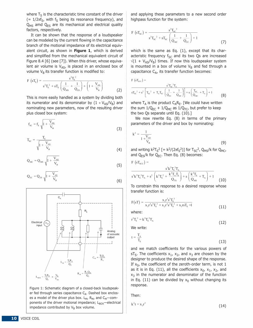
It can be shown that the response of a loudspeaker can be modeled by the current flowing in the capacitance branch of the motional impedance of its electrical equiv-alent circuit, as shown in Figure 1, which is derived and simplified from the mechanical equivalent circuit of Figure 8.4 [6] (see [7]). When this driver, whose equiva-lent air volume is VAS, is placed in an enclosed box of volume VB its transfer function is modified to:
F sT = s T
s T + sT 1Q
+ 1Q
+ 1 + VV
S
2S
2
2S
2S
MS ES
AS
B
( )⎛⎝⎜
⎞⎠⎟
⎛⎝⎜⎜
⎞⎠⎟
(2)
This is more easily handled as a system by dividing both its numerator and its denominator by (1 + VAS/VB) and nominating new parameters, now of the resulting driver plus closed box system:
fSC = f 1 + V
VSAS
B (3)
T TSC
S = 1 + V
VAS
B (4)
Q QMC MS = 1 + VV
AS
B (5)
Q QEC ES = 1 + VV
AS
B (6)
Figure 1: Schematic diagram of a closed-back loudspeak-er fed through series capacitance CA. Dashed box enclos-es a model of the driver plus box. LM, RM, and CM—com-ponents of the driver motional impedance; LBOX—electrical impedance contributed by VB box volume.
NOVEMBER 2012 11
k t
QTS
2 + 1 = x r22⎛
⎝⎜⎞⎠⎟ (15)
t + k
Q = x r2
MS1
(16)and then:
k2 = x rt3
3
(17)
t = 1xx r
1Q
2
3 TS
− (18)
and:
x r x
Q TS
23
3 22
2
2x x Q r + rQ Q + x x Q
Q x 2 3 TS
2TS TS 1 3 MS
MS 3
− ( )+ − x x = 01 2( ) (19)
The cubic Eq. (19) is solved for r. Of the methods available, the author prefers the iterative Newton–Raphson method [8] starting with an initial guess of 1 for r. In all cases investigated so far, only one positive real root was found, so no further calculation of r was necessary. The value of r, the ratio in which the reso-nance frequency fS and its characteristic time constant TS are changed to the new characteristic time constant rTS, is substituted in Eq. (18) to find t, hence also TA from Eq. (13). These values of r and t are substituted
in Eq. (17) to find k2, hence the ratio VAS/VB from Eq. (9), and then the required box volume VB. Finally the value of the series capacitance CA is: CA = T
RA
E (20)
USEFUL RESPONSE FUNCTIONS
The response shapes of a loudspeaker system most usu-ally desired bear the names of Butterworth, Chebyshev, and Bessel. Their third order low-pass versions are most familiar in the forms of Eqs. (21), (22), and (23), though later we will be
using the high-pass versions.
�������������� �����������������
F s( ) = 11 + 2sT + 2s T + s T0
2 20
3 30 (21)
�������������������������������
F s( )⎛⎝⎜
⎞⎠⎟
⎛⎝⎜
⎞⎠⎟
⎛⎝⎜
⎞⎠⎟
= 1 + 3K
4
1 + 3K4
+ 2 + 3K4
sT + 2s022 3 3
0 + s TT20
(22) ����������������������������
F s( ) = 15 + 15sT + 6s T + s T0
2 20
3 3015 (23)
The most generally useful function is the Butterworth, which produces a maximally flat amplitude response. Of all possible functions, its response inband remains the longest near reference level. At its characteristic frequency, when ωT0 = 1, that is f = f0, its response is 3.0 dB below reference level. At frequencies out of band its response remains closest to the asymptotic slope of all third-order functions, namely, 18 dB per octave (60 dB per decade).
The equal ripple Chebyshev response may be defined algebraically [9] as in Eq. (22), where the constant K determines the amount of ripple. The squared magnitude
Figure 2: Comparison of various third-order high-pass amplitude responses. –3.0 dB at ���������� ��������"����������������������#���������"�$�$����������������%����� ������"������������
Transfer Function Type f–3dB = f0 (Hz) VB (liters) QTC TA (μs) CA (μF)
Table 1: Parameters required for various transfer functions
12 VOICE COIL
|F(jω)2| of its low-pass response ripples, as in the dashed and dash–dot curves of Figure 2, between a maximum of 1 (0 dB) at high frequencies inband and also when ω2T02 = 3/4K and a minimum of 1/[1 + K3/(4 + 3K)2] when ω2T02 = ¼K and also K. When ω2T02 = K + 1 the squared magnitude goes through a value of 1/[2 + K3/(4 + 3K)2] that is not greatly different from –3.0 dB, that is, between –3.0 and –3.7 dB, at commonly used values of K between 0 and 5. When K diminishes to zero, the Chebyshev function degener-ates to a Butterworth.
However, for the present application it has proved more useful to take two values of K, 2.5481 and 4.0949, which produce ripple amplitudes of 0.5 and 1.0 dB, respectively, and then adjust the resulting coefficients in Eqs. (25) and (26) according to their
powers of sT0 so that the magnitude of both responses is –3.0 dB when ωT0 = 1.
��� ����������������������>�������
F s( ) = s T1 + 2sT + 2s T + s T
3 30
02 2
03 3
0 (24) �� ���������� ����������� ��>������ ?��#��� ������"�–3.0 dB when ωT0 = 1):
F s( ) = 0.4498s T1 + 1.7032sT + 1.1261s T + 0.4498s T
Figure 3: Comparison of driver excur-sions, various third-order high-pass responses. –3.0 dB at 30 Hz. — Butterworth; ———Chebyshev with ��#���������"�$������������������%�����������"�����������"�����fourth-order high-pass Butterworth, from vented box (for comparison).
Figure 4: Responses of driver of Table 1, resonance FS = 40 Hz; QT = 0.40; VAS = 50 liters. (a) Amplitude versus frequency. (b) Group delay versus frequency. —in 11.2-liter box and with a 900-μF capaci-tor in series, third-order Butterworth ����@��"�$�$��@�%%�Z�������\����� ��series capacitor; produces second-order response with 1.6-dB peak; ——— in 23.5-liter box without series capacitor, for second-order Butterworth response.
NOVEMBER 2012 13
F s s Ts T s T
( ) = + 0.9027sT + 1.0331 + 0
0 37431 0 3743
3 30
2 20
3 3
.. 00 (26)
The coefficients of the Bessel (maximally flat delay) response were adjusted likewise from the low-pass function of Eq. (23) to the high-pass function Eq. (27), whose response has a magnitude of–3.0 dB when ωT0 = 1. ��������� �������������>������ ?$����������@� ωT0 = 1):
F s s TsT s T s T
( ) = + + 4.6280 +
2 62371 3 4015 2 6237
3 30
02 2
03 3
.. . 00 (27)
It should be remembered that only one set (“align-ment”) of parameters can produce a given transfer function from a given driver. The values of the param-eters will vary with a number of factors—the closeness of the driver’s initial QT to the QT that the function requires, and to some extent, the ratio of QM to QE.
The alignments in Table 1 give some insight into the parameter values required with a typical driver to produce each of the four preceding responses above. QTC is the QT of the driver + box system. The capaci-tance values needed for CA are comparatively large, in the hundreds of microfarads. The capacitor needs to be chosen for a low series loss resistance, small compared with the resistance of RE, since its contribution to the total resistance in the circuit effectively increases QE in the same proportion.
The responses of the four functions are plotted in Figure 2 for responses that are all –3.0 dB at 30 Hz (for which T0 = 5305 μs). They demonstrate the much faster cutoff of the Chebyshev responses in the stop-band, though the improvement in going from 0.5-to 1.0-dB ripple is comparatively small. They also show how the Bessel’s amplitude response droops slowly across the pass-band.
The voice-coil excursions for these responses are plotted in Figure 3, and compared with the excur-sion of a ventedbox loudspeaker with a fourth-order Butterworth response. All curves are normalized to a maximum value of 1 for the excursion of the driver at very low frequencies with a standard level of input signal in the passband.
It should be remembered, though, that the driver’s voice coil excursion at very low frequencies has already been reduced 1/[1 + (VAS/VB)] times below its unbaf-fled value, the system compliance being stiffened by the air enclosed in the box.
Table 1 shows how the use of a series capacitor with a suitable driver allows good bass response to be launched from a surprisingly small box. Figure 4 shows how great the saving in box volume can be, 11.2 versus 23.5 liters, to less than half in this example.
The group delay plot of Figure 4 should be read in light of [10], where the threshold of audibility of the
group delay is reported as increasing from a minimum of 1 ms at 2 kHz to 2.0 ms at 8 kHz and 3.2 ms at 500 Hz, with no figures for thresholds beyond those frequencies. At the same time Figure 3 shows how much protection the additional highpass filtering con-fers against excessive excursion at very low frequen-cies. While a vented box has the clear advantage over all the closed-box responses that its cone excursion is much less in the region of cutoff, the designer must weigh this against the problems of increasing size and cost in providing a vent for a small box at low frequen-cies, or of a passive radiator.
CONCLUSIONWhen a capacitor is inserted in series with a closed-
box loudspeaker, it extends the response to lower fre-quencies and enables the use of a much smaller box. At the same time it confers substantial protection against excessive excursion of the voice coil from subsonic input signals that would produce no useful acoustic output. The design procedure is straightforward and is easily adapted to desirable transfer functions.
ACKNOWLEDGMENT The author gratefully acknowledges Graeme Huon’s
experimental verification of the design procedure and his helpful comments, along with those of the Journal’s reviewers, regarding the text. * The manuscript was received April 28, 2010; revised May 25, 2010 to run in the JAES.
THE AUTHORThe late A. Neville Thiele graduated from the
University of Sydney in 1952 with a Bachelor of Engineering (Mechanical and Electrical) degree.
From 1952 to 1961, at E.M.I. Ltd. (Australia), he worked on the development of telemetry, radio and television receivers, and electronic test equipment. In 1962, he joined the Australian Broadcasting Corp., where he designed and assessed equipment and sys-tems for sound and television broadcasting. From 1980 until his retirement in 1985, Mr. Thiele was its direc-tor of engineering research and development. Until his death, he was a consulting engineer in the fields of audio, radio, and television, and he taught in the University of Sydney graduate audio program.
Mr. Thiele published more 40 papers about loud-speakers, filters, and equalizers, and about testing methods for sound and video broadcasting. He helped set national and international standards, serving on Audio Engineering Society (AES) committees, ITU-R, and through Standards Australia. He was a Fellow of the AES and the Institution of Engineers, Australia, and a member of the Society of Motion Picture and Television Engineers. He was president of the Institution of Radio and Electronics Engineers Australia from 1986 to 1988 and vice president, AES’s international region from 1991 to 1993 and from 2001 to 2005. VC
14 VOICE COIL
filter for a low-frequency sound source mounted behind the waveguide in a multi-way loudspeaker system. The waveguide includes openings that overlay the vibrat-ing surface of the low-frequency source. The openings are configured by a selection of various geometrical parameters to tailor filtering characteristics as desired (see Photo 1).
Independent Claims1. A waveguide for mounting in a loudspeaker system
comprising: an outer surface shaped to direct sound waves radiated from a first sound source positioned to generate the sound waves directed by the wave-guide; an inner surface on a side opposite the outer surface; and a plurality of openings in the waveguide, each opening extending from the inner surface to the outer surface. The plurality of openings are disposed to overlay an acoustical radiating surface of a diaphragm
of a second sound source mount-ed adjacent to the waveguide’s inner surface such that the wave-guide’s inner surface covers the diaphragm’s acoustical radiating surface. The openings are config-ured to enable the waveguide to function as an acoustical low-pass filter for sound radiated through the openings from the second
By James Croft, Croft Acoustical
The following loudspeaker-related patents were filed primarily under the Office of Patent and Trademarks
classification 181 for acoustical devices and 381 for electrical-signal processing systems and HO4R for inter-national patents. This also includes new patent applica-tions that are published in the Patent Application Journal.
WAVEGUIDEU.S. Patent Number: 8,130,994Inventors: Douglas J. Button (Simi Valley, CA), Alexander V. Salvatti (Canoga Park, CA)Assignee: Harman International Industries (Northridge, CA) Filed: June 17, 2008U.S. Classes: 381/39Granted: March 6, 2012Number of Claims: 10Number of Drawings: 18
Abstract from PatentA waveguide configured to func-
tion as a high-frequency waveguide for a high-frequency sound source mounted to the waveguide, and to function as an acoustical low-pass
Acoustic Patents
128 120
122
130
132126124
Photo 1: U.S. Patent Number: 8,130,994
Dayton Audio’s OmniMic V2 is a must-have omnidirectional acoustic measurement system for audio system
integrators, acoustic engineers, and residential A/V installers. The OmniMic V2’s new hardware provides fast, comprehensive,
and accurate audio measurements.
The Dayton Audio DATS is the most complete and easy-to-use audio test system toolkit yet! From seasoned pros to hobbyists, everyone can improve their loudspeaker systems by using the
Dayton Audio Test System to gather over 30,000 points of essential data in mere seconds.
Distributed By:
Tel:800-338-0531725 Pleasant Valley Dr.Springboro, OH 45066
parts-express.com/vcm
In Europe:
intertechnik.de
In Asia:
baysidenet.jp
In Canada:
solen.ca
NOVEMBER 2012 15
sound source where the function of the waveguide as the acoustical low-pass filter depends on the distance between the diaphragm and the inner surface of the waveguide. The area between the openings creates a compression chamber between the inner surface of the waveguide and the acoustic radiating surface when the diaphragm of the second sound source vibrates, and a selected area of the openings, a ratio of area of the diaphragm to the area of the openings, and the distance between the diaphragm and the waveguide’s inner surface are selected by simulating operation of the second source using an equivalent electri-cal circuit model.
5. A loudspeaker system comprising: a first sound source; a second sound source having an acoustical radi-ating surface; and a waveguide mounted acoustically in front of the second sound source such that the waveguide covers the acoustical radiating surface of the second sound source. The waveguide has an outer surface shaped to direct sound waves radiated from a sound source posi-tioned at an opening in the waveguide; an inner surface on a side opposite the outer surface; and a plurality of openings in the waveguide. Each opening extends from the inner surface to the outer surface, with the plurality of openings disposed to overlay the acoustical radiat-ing surface of a diaphragm of the second sound source. The openings are configured to enable the waveguide to function as an acoustical low-pass filter for sound radi-ated through the openings from the second sound source where the waveguide’s function as the acoustical low-pass filter depends on the distance between the diaphragm and the waveguide’s surface adjacent to the diaphragm. The area between the openings creates a compression chamber between the waveguide’s inner surface and the acoustic radiating surface when the second sound source’s diaphragm vibrates, and where a selected area of the openings, and ratio of area of the diaphragm to the area of the opening, the distance between openings, and the distance between the diaphragm and the surface of the waveguide adjacent to the diaphragm are selected by simulating the waveguide’s operation with a selected low-frequency sound driver using an equivalent electrical circuit model.
Reviewer Comments A waveguide is disclosed that operates as a dual-
purpose high-frequency transducer waveguide and an acoustical low-pass filter for a low-frequency concave cone-type transducer. The waveguide includes an outer surface shaped to direct sound waves radiated from a high-frequency sound source positioned at a cen-tral opening in the waveguide’s throat. The waveguide includes a plurality of openings through the waveguide’s surface. The plurality of openings cover the majority of diaphragm surface area of a second, low-frequency sound source mounted adjacent to the waveguide’s inner surface. The openings are configured to enable the wave-guide to function as an acoustical low-pass filter for sound radiated through the openings from the low-frequency
source, preshaping the upper-frequency response of the low-frequency driver. At the same time, the waveguide includes an outer surface shaped to direct sound waves radiated from the first high-frequency sound source posi-tioned at the waveguide’s throat opening.
This type of waveguide architecture that enables the high-frequency transducer waveguide to operate coaxially as a low-pass filter with a low-frequency transducer was first realized, and thoroughly developed, by Marshall Buck when he was working for Cerwin Vega back in the 1980s (U.S. 4,283,606 and U.S. 4,619,342) and more recently for Gibson Guitar (U.S. 7,392,880).
While the novelty contribution in the currently reviewed patent is minimal, in general, the technique is a good solution to the problem of using large, lower frequency waveguides with large woofers. Normally, a large wave-guide that can operate down to 1 to 2 kHz, when com-bined with a woofer of similar diameter, causes a center-to-center spacing that is too large to prevent off-axis lobing and comb filtering. With this technique, one can rearrange the components into a coaxial structure and match the directivity at the crossover frequency and tame the off-axis behavior. Additionally, it may provide a means to match a smaller low-frequency driver to a larger high-frequency waveguide while still maintaining substantially constant directivity down to a lower frequency and match-ing directivity at the crossover frequency.
With a device of this type, one of the key design ele-ments is that of the design conflict between making the through hole slots in the waveguide large enough to be adequately acoustically transparent relative to the low-frequency transducer behind the waveguide, while at the same time making the openings small enough to enable the waveguide surface to not be so porous as to enable the high-frequency content to expand through the waveguide instead of the waveguide fully supporting the high-frequency wavefronts as they transition to the waveguide’s mouth.
Marshall Buck’s earlier designs incorporated many small circular openings, looking like a vegetable colander. The new version, developed at JBL by Douglas Button and Alexander Salvatti, uses pie-shaped slots that expand near the edge of the mouth and are significantly larger than the Buck designs’ individual openings. Intuitively, it appears the large slot openings might be problematic, compared to the earlier prior art, but in most embodi-ments, they are either very narrow near the throat or don’t start until they are some distance from the throat, such that the high-frequency wavefront is more fully developed before traversing the slots. With most acoustic low-filter devices, an additional benefit is the distortion harmonics being suppressed. While this has not been proven to offer an audible advantage, the performance improvement can be seen in the measurements.
All in all, when properly applied, the invention should be a useful tool in providing an effective point source while optimizing directivity control and it should have the bonus of providing a novel industrial design element. VC
16 VOICE COIL
SpotlightTime Synchronous AveragingBy Christopher Struck, CJS Labs
When performing electroacoustical response mea-surements, an important practical consideration
is the reduction of uncorrelated background noise. Synchronous averaging (i.e., “complex averaging,” “time domain averaging,” or “vector averaging”) is a technique originally developed to analyze the vibra-tion signature or rotating machines and gearboxes. It can be used to improve the S/N ratio measurement. In a loudspeaker test, a correlated test stimulus, which is identical for every record, adds on a “Signal” basis (i.e., 2x = X + 6 dB), while the uncorrelated background noise, which is the same level (but not the same signal), adds on a power basis (i.e., 2x2 = X + 3 dB).
In Figure 1 all samples are treated as complex vec-tors (i.e., magnitude and phase), rather than simple power averaging. Therefore, an effective measurement S/N increase of 3 dB is gained for every doubling of either the measurement time or the number of complex averages. Most analysis systems and time-selective techniques offer this option. The stimulus may be a sinu-soid or a pseudo-random noise signal (i.e., a repetitive random noise with a period equal to the analysis record length).
Since the averaging is complex and correlated, increasing the number of averages (i.e., sweep time)
effectively lengthens the time window. Seen in the frequency domain, this is a narrowing of the main lobe of the Fourier transform of the time window, a sin(x)/x function. This can also be viewed as a more selective filter, thus reducing noise at all other frequencies. This is the effective bandwidth of the analysis, as shown in the diagram, where B is the ini-tial filter bandwidth for the analysis (see Figure 2).
Note that for a 3-dB increase, the length of each data progressively doubles. So, the price to pay for a 3-dB improvement in measurement S/N is a geo-metrically increasing measurement time (i.e., two averages or double the sweep time; four averages or quadruple the sweep time; eight averages or 8 × sweep time; 16 averages; etc.). Note also that since the stimulus is synchronized to the analysis record and is zero at the beginning and end of each data block, no time window is required.
For a white background noise spectrum, the approximate amount of additional noise reduction can be computed as 20 log10^_� where N is the number of averages.
About the AuthorChristopher J. Struck is CEO and chief scientist
of CJS Labs, a consulting firm in San Francisco, CA, specializing in audio and electroacoustics. His areas of expertise include transducers, acoustics, system design, instrumentation, measurement and analy-sis techniques, hearing science, telephonometry, speech intelligibility, technology strategy, and train-ing services.
Prior to founding CJS Labs, Christopher held positions at Brüel & Kjær, Dolby, and Tymphany. He is an Acoustical Society of America member, a senior member of the Institute of Electrical and Electronics Engineers, and an Audio Engineering Society fellow. Currently, he is the chairman and an Individual Accredited Expert of the American National Standards Institute/Acoustical Society of America Subcommittee 3, responsible for standards development in bioacoustics and related fields. VC
CONNECT WITHloudspeaker professionals from around the globe. Reserve advertising space in Voice Coil and the Loudspeaker Industry Sourcebook.
Figure 1: Time-synchronous system analysis with additive background noise
Time Domain
DataBlock 1
DataBlock 2
DataBlock 3
DataBlock N
Timet1 t2
Frequency Domain
Additional filteringeffect due to increased
complex averaging
FrequencyBN
fHarmonic
B
Figure 2: Effective bandwidth versus number of averages
NOVEMBER 2012 17
Pro Sound Coax from B&C and a New Professional Series 15” from Eminenceby Vance Dickason
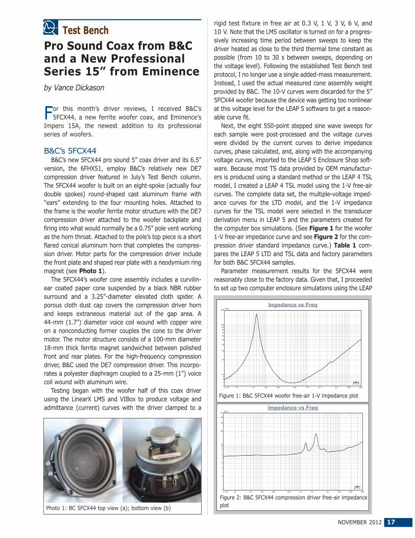
For this month’s driver reviews, I received B&C’s 5FCX44, a new ferrite woofer coax, and Eminence’s
Impero 15A, the newest addition to its professional series of woofers.
B&C’s 5FCX44B&C’s new 5FCX44 pro sound 5” coax driver and its 6.5”
version, the 6FHX51, employ B&C’s relatively new DE7 compression driver featured in July’s Test Bench column. The 5FCX44 woofer is built on an eight-spoke (actually four double spokes) round-shaped cast aluminum frame with “ears” extending to the four mounting holes. Attached to the frame is the woofer ferrite motor structure with the DE7 compression driver attached to the woofer backplate and firing into what would normally be a 0.75” pole vent working as the horn throat. Attached to the pole’s top piece is a short flared conical aluminum horn that completes the compres-sion driver. Motor parts for the compression driver include the front plate and shaped rear plate with a neodymium ring magnet (see Photo 1).
The 5FCX44’s woofer cone assembly includes a curvilin-ear coated paper cone suspended by a black NBR rubber surround and a 3.25”-diameter elevated cloth spider. A porous cloth dust cap covers the compression driver horn and keeps extraneous material out of the gap area. A 44-mm (1.7”) diameter voice coil wound with copper wire on a nonconducting former couples the cone to the driver motor. The motor structure consists of a 100-mm diameter 18-mm thick ferrite magnet sandwiched between polished front and rear plates. For the high-frequency compression driver, B&C used the DE7 compression driver. This incorpo-rates a polyester diaphragm coupled to a 25-mm (1”) voice coil wound with aluminum wire.
Testing began with the woofer half of this coax driver using the LinearX LMS and VIBox to produce voltage and admittance (current) curves with the driver clamped to a
Test Benchrigid test fixture in free air at 0.3 V, 1 V, 3 V, 6 V, and 10 V. Note that the LMS oscillator is turned on for a progres-sively increasing time period between sweeps to keep the driver heated as close to the third thermal time constant as possible (from 10 to 30 s between sweeps, depending on the voltage level). Following the established Test Bench test protocol, I no longer use a single added-mass measurement. Instead, I used the actual measured cone assembly weight provided by B&C. The 10-V curves were discarded for the 5” 5FCX44 woofer because the device was getting too nonlinear at this voltage level for the LEAP 5 software to get a reason-able curve fit.
Next, the eight 550-point stepped sine wave sweeps for each sample were post-processed and the voltage curves were divided by the current curves to derive impedance curves, phase calculated, and, along with the accompanying voltage curves, imported to the LEAP 5 Enclosure Shop soft-ware. Because most TS data provided by OEM manufactur-ers is produced using a standard method or the LEAP 4 TSL model, I created a LEAP 4 TSL model using the 1-V free-air curves. The complete data set, the multiple-voltage imped-ance curves for the LTD model, and the 1-V impedance curves for the TSL model were selected in the transducer derivation menu in LEAP 5 and the parameters created for the computer box simulations. (See Figure 1 for the woofer 1-V free-air impedance curve and see Figure 2 for the com-pression driver standard impedance curve.) Table 1 com-pares the LEAP 5 LTD and TSL data and factory parameters for both B&C 5FCX44 samples.
Parameter measurement results for the 5FCX44 were reasonably close to the factory data. Given that, I proceeded to set up two computer enclosure simulations using the LEAP
LTD parameters for Sample 1. This included two vented alignments. The QB3 alignment for this driver was too small to be realistically feasible, so I choose a larger Extended Bass Shelf (EBS) and used two different vent tunings. This resulted in a 205-ci box with 15% fiberglass fill material tuned to 85 Hz, and the same 205-ci box but with an EBS-vented alignment tuned to 65 Hz, with 15% fiberglass fill material.
Figure 3 displays the results for the 5FCX44 woofer section in the two vented boxes at 2.83 V and at a voltage level sufficiently high enough to increase cone excursion to XMAX + 15% (3.45 mm for the 5FCX44). This produced a F3 frequency of 81 Hz for the 205-ci box tuned to 85 Hz and –3 dB = 63 Hz for the 205-ci box EBS-vented simulation tuned to 65 Hz. Increasing the voltage input to the simula-tions until the maximum linear cone excursion was reached resulted in 107 dB at 20 V for the 65-Hz tuning enclosure simulation and 105.2 dB with the same 20-V input (see Figure 4 and Figure 5 for the 2.83-V group delay curves and the 20-V excursion curves). If you look at the excur-sion curves, the driver exceeds the XMAX + 15% criteria at 61 Hz for the 65-Hz tuning and 49 Hz for the 85-Hz tuning. Both alignments would benefit from an appropriately placed high-pass filter, as is generally true of all vented enclosures.
Klippel analysis for the B&C 5FCX44 produced the Bl(X), KMS(X) and Bl and KMS symmetry range plots shown in Figures 6–9. (Klippel GmbH provided our analyzer and Pat Turnmire, Red Rock Acoustics, performs the analysis).
10 Hz 20 50 100 200 500 1K
dBSPL
65
70
75
80
85
90
95
100
105
110
115
SPL vs Freq
Figure 3: B&C 5FCX44 computer box simulations (black solid = vented 1 at 2.83 V; blue dash = vented 2 at 2.83 V; black solid = vented 1 at 20 V; blue dash = vented 2 at 120 V)
Table 1: B&C 5FCX44 coax woofer
TSL Model LTD Model Factory
Sample 1 Sample 2 Sample 1 Sample 2
FS 59.1 Hz 57.1 Hz 59.2 Hz 57.5 Hz 61 Hz
REVC 6.07 6.1 6.07 6.1 5.6
Sd 0.0092 0.0092 0.0092 0.0092 0.0095
QMS 7.16 6.8 6.66 6.42 7.8
QES 0.26 0.25 0.26 0.25 0.25
QTS 0.25 0.24 0.25 0.24 0.25
VAS 7.03 ltr 7.55 ltr 7.06 ltr 8.34 ltr 7 ltr
SPL 2.83 V 89.4 dB 89.4 dB 89.4 dB 89.2 dB 91 dB (1 W/1 m)
XMAX 3 mm 3 mm 3 mm 3 mm 3 mm
NOVEMBER 2012 19
This data is extremely valuable for transducer engineer-ing, so if you don’t own a Klippel analyzer and would like to have analysis done on a particular driver project, Red Rock Acoustics can provide Klippel analysis on almost any driver for $140 per unit. For contact information, visit www.redrockacoustics.com.
The 5FCX44 woofer’s Bl(X) curve looks quite good and is moderately broad, and is symmetrical (see Figure 6).The Bl symmetry plot is pretty much 0.0 from the rest position to beyond the physical XMAX, so nearly perfect from this standpoint (see Figure 7). Figure 8 and Figure 9 show the KMS (X) and KMS symmetry range curves for the 5FCX44. The KMS (X) curve is also quite symmetrical in both directions, with a small amount of coil-in (rearward) offset. Looking at the KMS symmetry curve, the offset is 0.22 mm at the zero rest position, and only increases to 0.26 mm at the physical XMAX, so again, it’s nearly perfect. Displacement-limiting numbers calculated by the Klippel analyzer for the 5FCX44 were XBl at 82% (Bl decreasing to 82% of its maximum value) was 2.7 mm and for XC at 75% (compliance decreasing to 75% of its maximum value) was 2.8 mm, which means that for the 5FCX44, the compliance is the most limiting factor at the 10% prescribed distortion level, but not significantly. If we apply the more liberal 20% distortion criteria, and given the relative difficulty of perceiv-ing THD, the numbers for XBl = 3.7 mm and XC = 4.5 mm, both numbers beyond the physical XMAX.
Figure 10 shows the inductance curve L(X) for the B&C
10 Hz 20 50 100 200 500 1K
Sec
0
5m
10m
15m
20m
Time vs Freq
Figure 4: Group delay curves for the 2.83-V curves in Figure 3
10 Hz 20 50 100 200 500 1K
M
1m
2m
3m
4m
5m
6m
7m
8m
9m
10m
Excursion vs Freq
Figure 5: Cone excursion curves for the 20-V curves in Figure 3
Vance Dickason Consulting has been developing award winning products for numerous high profile brand names for over 20 years… experience that’s hard to find!
With extensive experience in high-end off-wall, in-wall, on-wall, ceiling and subwoofer products plus close relationships with some of the worlds best speaker OEM’s and you have a combination of services that will accelerate your next product lineup.
We have all the best toys (Klippel, LEAP 5,LMS, CLIO, MLSSA, LSPCad, FEA), so whether its multimedia, car audio, MI, Pro, two-channel or Home Theater (including THX®), VDC has the solutions.
Add to that an available design team that includes some of the best transducers engineers, industrial designers and marketing experts I know of in the industry and you have a winning combination that would cost well over $750,000 a year to keep in house.
20 VOICE COIL
to 40 kHz for the woofer and compression driver/horn. This was performed at 2.83 V/1 m using the LMS gated sine wave technique. Figure 11 shows the 5FCX44 woofer on-axis response combined with the DE7/horn on-axis response. The woofer response shows a smooth rising response with the typical response decline above 1.1 kHz due to the baffle width, followed by a 7-dB breakup peak prior to the low-pass rolloff. For the compression driver/horn, the response is ±2.9 dB from 1.4 to 7.4 kHz starting its low-pass rolloff above 7.4 kHz.
Figure 12 depicts the woofer on- and off-axis frequency response at 0°, 15°, 30°, and 45°. With respect to the on-axis curve, –3 dB at 30° occurs somewhat low for a 5” driver at 2.1 kHz, making 2 to 2.5 kHz a reasonable crossover range. (B&C recommends a 2.5-kHz crossover frequency for the DE7.) And last, Figure 13 shows the two-sample SPL comparisons for the 5FCX44 woofer samples. Both are obviously closely matched.
For the compression driver with the short conical horn, Figure 14 illustrates the on- and off-axis frequency response out to 45°, while Figure 15 provides the two-sample SPL comparison, which is good throughout the entire frequency range with some variation above 8.5 kHz.
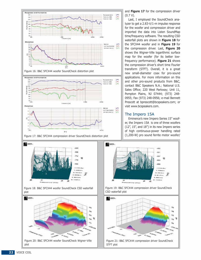
The last group of tests were performed using the Listen SoundCheck analyzer and SC-1 microphone (courtesy of Listen) to measure distortion and generate time-frequency plots. Set up for the distortion measurement consisted of mounting the driver rigidly in free air, and using a noise stim-ulus to set the SPL to 104 dB at 1 m. (Two of SoundCheck’s utilities are a software generator and SPL meter.) The dis-tortion was measured with the Listen microphone placed 10 cm from the dust cap/horn mouth. This produced the distortion curves shown in Figure 16 for the woofer (8.2 V)
Figure 10: Klippel analyzer L(X) curve for the B&C 5FCX44
300 Hz 500 1K 2K 5K 10K 20K 40K
dBSPL
55
60
65
70
75
80
85
90
95
100
105
110
115
SPL vs Freq
Figure 11: B&C 5FCX44 woofer and DE7 compression driver/horn on-axis frequency response
coax woofer. Inductance will typically increase in the rear direction from the zero rest position as the voice coil covers more pole area, unless the driver incorporates a shorting ring. Since the 5FCX44 does not incorporate a faraday shield (shorting ring) in the motor assembly, we see the typical inductance rise for the motion’s coil-in direction. However, from XMAXIN to XMAXOUT, the inductive change is about 0.46 mH.
Next, I mounted the B&C 5FCX44 in an enclosure that had a 15” × 16” baffle and was filled with damping material (foam) and measured the woofer and the compression driv-er/horn on- and off-axis frequency response from 300 Hz
Figure 7: Klippel analyzer Bl symmetry range curve for the B&C 5FCX44
Figure 6: Klippel analyzer Bl (X) curve for the B&C 5FCX44
Figure 9: Klippel analyzer KMS symmetry range curve for the 5FCX44
Figure 8: Klippel analyzer mechanical stiffness of suspension KMS (X) curve for the B&C 5FCX44
NOVEMBER 2012 21
Figure 12: B&C 5FCX44 woofer on- and off-axis frequency response (black solid = 0°, blue dot = 15°, green dash = 30°, purple dash dot = 45°)
300 Hz 500 1K 2K 5K 10K 20K 40K
dBSPL
40
45
50
55
60
65
70
75
80
85
90
95
100
SPL vs Freq
Figure 14: B&C 5FCX44 compression driver on- and off-axis frequency response (black solid = 0°, blue dot = 15°, green dash = 30°, purple dash dot = 45°)
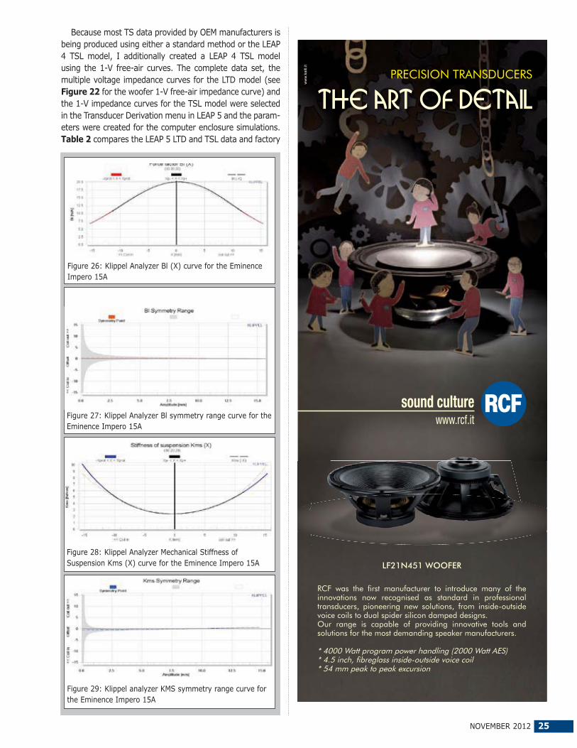
Last, I employed the SoundCheck ana-lyzer to get a 2.83-V/1-m impulse response for the woofer and compression driver and imported the data into Listen SoundMap time/frequency software. The resulting CSD waterfall plots are shown in Figure 18 for the 5FCX44 woofer and in Figure 19 for the compression driver. Last, Figure 20 shows the Wigner-Ville logarithmic surface map for the woofer (for its better low-frequency performance). Figure 21 shows the compression driver’s short time Fourier transform (STFT). Overall, it is a great new small-diameter coax for pro-sound applications. For more information on this and other pro-sound products from B&C, contact B&C Speakers N.A.; National U.S. Sales Office; 220 West Parkway; Unit 11, Pompton Plains, NJ 07444; (973) 248-0955; Fax (973) 248-0956; e-mail Bennett Prescott at [email protected]; or visit www.bcspeakers.com.
The Impero 15AEminence’s new Impero Series 15” woof-
er, the Impero 15A is one of three woofers (12”, 15”, and 18”) in its new Impero series of high continuous-power handling rated (1,200-W) pro sound ferrite motor woofer/
subwoofers (see Photo 2). Anything that goes much lower than 35 to 40 Hz is pretty much a subwoofer in the pro-sound world. As the price of neodymium has soared, the industry has seen a number of new ferrite-motor based woofers in various loudspeaker markets including home, pro, and mobile audio.
This kind of performance’s feature set is substantial, starting with a proprietary cast frame. This frame has six spokes, each with reinforced edges that can contribute to the rigidity needed to handle the 25.4-lb weight, most of it in the motor assembly. For mounting, the Impero 15A has a foam rear gasket and a high-density polyethylene front-mounting gasket.
This woofer seems to take the old school approach of pull-ing heat out of the voice coil with a large motor mass, and thus doesn’t have the venting below the spider or peripheral venting that is common in a lot of woofers. The primary cooling feature is a 32-mm (1.25”) diameter pole vent.
The cone assembly consists of a ribbed 15” cone that is coated on the front sides with a “wet” look acrylic treatment plus a large 5” diameter convex acrylic-coated dust cap. Compliance is provided by a double roll coated cloth M-shaped surround and a 6” diameter coated flat cloth spider assembly mounted on a 1” high metal mounting shelf that is part of the cast frame. Coupling the cone assembly to the motor is a 4” (100 mm) diameter voice coil wound on a fiberglass former wound with round copper wire.
Horsepower for this 25-lb beast is provided by a large 25-mm thick, 205-mm diameter ceramic ferrite ring mag-net. Other motor features include a CNCed zinc-coated bumped-out T-Yoke and 12.7-mm (0.5”) thick CNCed pol-ished front plate. Last, the voice coil tinsel wires are con-nected to a set of chrome color coded five-way binding post (Note: The fifth mounting way for a five-way mounting post is using alligator clips. Now that is old school!)
Testing for the Impero 15A began using the LinearX LMS and VIBox to produce both voltage and admittance (current) curves with the driver clamped to a rigid test fixture in free air at 1 V, 3 V, 6 V, 10 V, 15 V, 20 V, and 30 V. Note that the driver remained linear in free air up to the 30-V sweep and probably would have remained linear up to 35 or 40 V, but with 95.6-dB sensitivity, 30 to 40 V is usually my limit when wearing ear protectors. Also, please note that I use a procedure that attempts to achieve the third-time constant on each sweep, the LMS oscillator is turned on for a progres-sively increasing time period between sweeps (10 to 30 s). Also, following the established Test Bench test protocol, I no longer use a single added mass measurement and instead used actual measured cone assembly weight provided by Eminence.
Next, the 14 550-point stepped sine wave sweeps for each sample were post-processed and the voltage curves were divided by the current curves to derive impedance curves, phase calculated and along with the accompany-ing voltage curves, imported to the LEAP 5 Enclosure Shop software. Obviously, this is a much more time-consuming process that the usual low-voltage impedance curve used for deriving Thiele-Small parameters. The reason for this, if you haven’t been following this column for a number of years, is that the LEAP 5 LTD transducer model methodology results in a much more accurate prediction of excursion at high voltage levels, one of the real fortes of the LEAP 5 software.
10 Hz 20 50 100 200 500 1K
dBSPL
80
85
90
95
00
05
10
15
20
25
30
SPL vs Freq
Figure 23: Eminence Impero 15A computer box simulations (black solid= vented 1 at 2.83 V; blue dash = vented 2 at 2.83 V; black solid = vented 1at 65 V; blue dash = vented 2 at 65 V)
10 Hz 20 50 100 200 500 1K
Sec
0
0m
20m
30m
40m
Time vs Freq
Figure 24: Group delay curves for the 2.83-V curves in Figure 23
10 Hz 20 50 100 200 500 1K
M
1m
2m
3m
4m
5m
6m
7m
8m9m
10m
20m
Excursion vs Freq
Figure 25: Cone excursion curves for the 65-V curves in Figure 23
www.ALMAInternational.org | 978.772.6977
ALMAINTERNATIONAL
®
Join today!
Be a part ofthe action –
Association of LoudspeakerManufacturing & Acoustics International
WINTER SYMPOSIUM, JAN. 6 & 7, 2013, LAS VEGASALMA is the only international trade association dedicatedto improving the design and manufacture of loudspeakers.
NOVEMBER 2012 25
Because most TS data provided by OEM manufacturers is being produced using either a standard method or the LEAP 4 TSL model, I additionally created a LEAP 4 TSL model using the 1-V free-air curves. The complete data set, the multiple voltage impedance curves for the LTD model (see Figure 22 for the woofer 1-V free-air impedance curve) and the 1-V impedance curves for the TSL model were selected in the Transducer Derivation menu in LEAP 5 and the param-eters were created for the computer enclosure simulations. Table 2 compares the LEAP 5 LTD and TSL data and factory
Figure 27: Klippel Analyzer Bl symmetry range curve for the Eminence Impero 15A
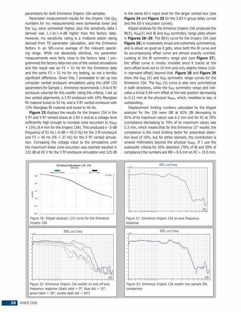
Figure 26: Klippel Analyzer Bl (X) curve for the Eminence Impero 15A
Figure 28: Klippel Analyzer Mechanical Stiffness of Suspension Kms (X) curve for the Eminence Impero 15A
Figure 29: Klippel analyzer KMS symmetry range curve for the Eminence Impero 15A
PRECISION TRANSDUCERS
the art of detail
ww
w.k
aiti.
it
RCF was the first manufacturer to introduce many of the innovations now recognised as standard in professional transducers, pioneering new solutions, from inside-outside voice coils to dual spider silicon damped designs.Our range is capable of providing innovative tools and solutions for the most demanding speaker manufacturers.
* 4000 Watt program power handling (2000 Watt AES)* 4.5 inch, fibreglass inside-outside voice coil* 54 mm peak to peak excursion
LF21N451 WOOFER
sound culturewww.rcf.it
26 VOICE COIL
in the same 65-V input level for the larger vented box (see Figure 24 and Figure 25 for the 2.83-V group delay curves and the 65-V excursion curves).
Klippel analysis for the Emience Impero 15A produced the Bl(X), KMS(X) and Bl and KMS symmetry range plots shown in Figures 26–29. The Bl(X) curve for the Impero 15A (see Figure 26) is moderately broad and extremely symmetrical, and is about as good as it gets, since both the Bl curve and its accompanying offset curve are almost exactly overlaid. Looking at the Bl symmetry range plot (see Figure 27), the offset curve is mostly invisible since it tracks at the zero-offset level out to 10 mm and only slightly below (coil-in rearward offset) beyond that. Figure 28 and Figure 29 show the KMS (X) and KMS symmetry range curves for the Eminence 15A. The KMS (X) curve is also very symmetrical in both directions, while the KMS symmetry range plot indi-cates a trivial 0.49-mm offset at the rest position decreasing to 0.12 mm at the physical XMAX, which, needless to say, is outstanding.
Displacement limiting numbers calculated by the Klippel analyzer for the 15A were XBl at 82% (Bl decreasing to 82% of its maximum value) was 6.3 mm and for XC at 70% (compliance decreasing to 70% of its maximum value) was 5.3 mm, which means that for this Eminence 15” woofer, the compliance is the most limiting factor for prescribed distor-tion level of 10%, but for either element, the contribution is several millimeters beyond the physical XMAX. If I use the subwoofer criteria for 20% distortion (70% of Bl and 50% of compliance) the numbers are XBl = 8.5 mm an XC = 19.5 mm,
Figure 31: Eminence Impero 15A on-axis frequency response
Figure 30: Klippel analyzer L(X) curve for the Eminence Impero 15A
parameters for both Eminence Impero 15A samples.Parameter measurement results for the Impero 15A QTS
numbers for my measurements were somewhat lower and the VAS were somewhat higher, plus the sensitivity data I derived was 1.1-to-1.4-dB higher than the factory data. However, my sensitivity rating is a midband piston rating derived from TS parameter calculation, and the Eminence factory in an SPL-curve average of the relevant operat-ing range. While not absolutely identical, my parameter measurements were fairly close to the factory data. I pro-grammed the factory data into one of the vented simulations and the result was an F3 = 51 Hz for the Eminence data and the same F3 = 51 Hz for my testing, so not a terribly significant difference. Given this, I proceeded to set up two computer vented enclosure simulations using the LEAP LTD parameters for Sample 1. Eminence recommends 1.9-to-6 ft3
enclosure volumes for this woofer. Using this criteria, I set up two vented alignments, a 3 ft3 enclosure with 15% fiberglass fill material tuned to 52 Hz, and a 5 ft3 vented enclosure with 15% fiberglass fill material and tuned to 44 Hz.
Figure 23 displays the results for the Impero 15A in the 3 ft3 and 5 ft3 vented boxes at 2.83 V and at a voltage level sufficiently high enough to increase cone excursion to XMAX + 15% (8.4 mm for the Impero 15A). This produced a –3-dB frequency of 51 Hz (–6 dB = 45.0 Hz) for the 3 ft3 enclosure and F3 = 40 Hz (F6 = 37 Hz) for the 5 ft3 vented simula-tion. Increasing the voltage input to the simulations until the maximum linear cone excursion was reached resulted in 123 dB at 65 V for the 3 ft3 enclosure simulation and 125 dB
NOVEMBER 2012 27
both numbers beyond the physical XMAX of 7.3 mm.
Figure 30 shows the inductance curve L(X) for the Eminence pro sound woofer. Inductance will typically increase in the rear direction from the zero rest position as the voice coil covers more pole area, which is what we see here. The inductive “swing” from XMAXIN to XMAXOUT is about 1 mH.
Following the Klippel testing, I mounted the Impero 15A” woofer in an enclosure that had a 17” × 17” baffle and was filled with damping material (foam) and mea-sured the DUT on- and off-axis from 300 Hzto 10 kHz frequency response at 2.83 V/1 musing a 100-point gated sine wave sweep. Figure 31 shows the 15A’s on-axis response displaying a very smooth response to about 2 kHz before the start of the low-pass rolloff. Figure 32 has the on- and off-axis frequency response at 0°, 15°, 30°, and 45°. With respect to the on-axis curve –3 dB at 30° occurs at 1.1 kHz, so a cross point in the vicinity of 1 kHz should be fine. The last SPL measurement is shown in Figure 33 and gives the two-sample SPL comparisons for the Impero 15A driver, showing a close less than 0.5 dB match up to nearly 2 kHz, with about 1-dB variations above that frequency.
I moved on to the last group of tests, which were per-formed using the Listen SoundCheck analyzer, Listen SC-1 microphone, and SoundConnect power supply to measure
distortion and time/frequency plots using SoundMap soft-ware. Set up for the distortion measurement consisted of mounting the woofer rigidly in free air, with the SPL set to 104 dB at 1 m using a noise stimulus. I then measured the distortion with the Listen microphone placed 10 cm from the dust cap. This produced the distortion curves shown in Figure 34.
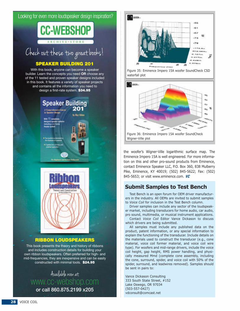
I then employed the SoundCheck analyzer to get a 2.83-V/1-m impulse response for the Eminence woofer and imported the data into the SoundMap time/frequency soft-ware. The resulting CSD waterfall plots for the Impero 15A woofer are shown in Figure 35. Last, Figure 36 shows
28 VOICE COIL
Test Bench is an open forum for OEM driver manufactur-ers in the industry. All OEMs are invited to submit samples to Voice Coil for inclusion in the Test Bench column.
Driver samples can include any sector of the loudspeak-er market, including transducers for home audio, car audio, pro sound, multimedia, or musical instrument applications.
Contact Voice Coil Editor Vance Dickason to discuss which drivers are being submitted.
All samples must include any published data on the product, patent information, or any special information to explain the functioning of the transducer. Include details on the materials used to construct the transducer (e.g., cone material, voice coil former material, and voice coil wire type). For woofers and mid-range drivers, include the voice coil height, gap height, RMS power handling, and physi-cally measured Mmd (complete cone assembly, including the cone, surround, spider, and voice coil with 50% of the spider, surround, and leadwires removed). Samples should be sent in pairs to:
Vance Dickason Consulting333 South State Street, #152Lake Oswego, OR 97034(503-557-0427)[email protected]
Submit Samples to Test Bench
the woofer’s Wigner-Ville logarithmic surface map. The Eminence Impero 15A is well engineered. For more informa-tion on this and other pro-sound products from Eminence, contact Eminence Speaker LLC, P.O. Box 360, 838 Mulberry Pike, Eminence, KY 40019; (502) 845-5622; Fax: (502) 845-5653; or visit www.eminence.com. VC
RIBBON LOUDSPEAKERS This book presents the theory and history of ribbons and includes construction details for building your
own ribbon loudspeakers. Often preferred for high- and mid-frequencies, they are inexpensive and can be easily
constructed with minimal tools. $24.95
Looking for even more loudspeaker design inspiration?
SPEAKER BUILDING 201 With this book, anyone can become a speaker
builder. Learn the concepts you need OR choose any of the 11 tested and proven speaker designs included in this book. It features a variety of speaker projects
and contains all the information you need to design a first-rate system. $34.95
NOVEMBER 2012 29
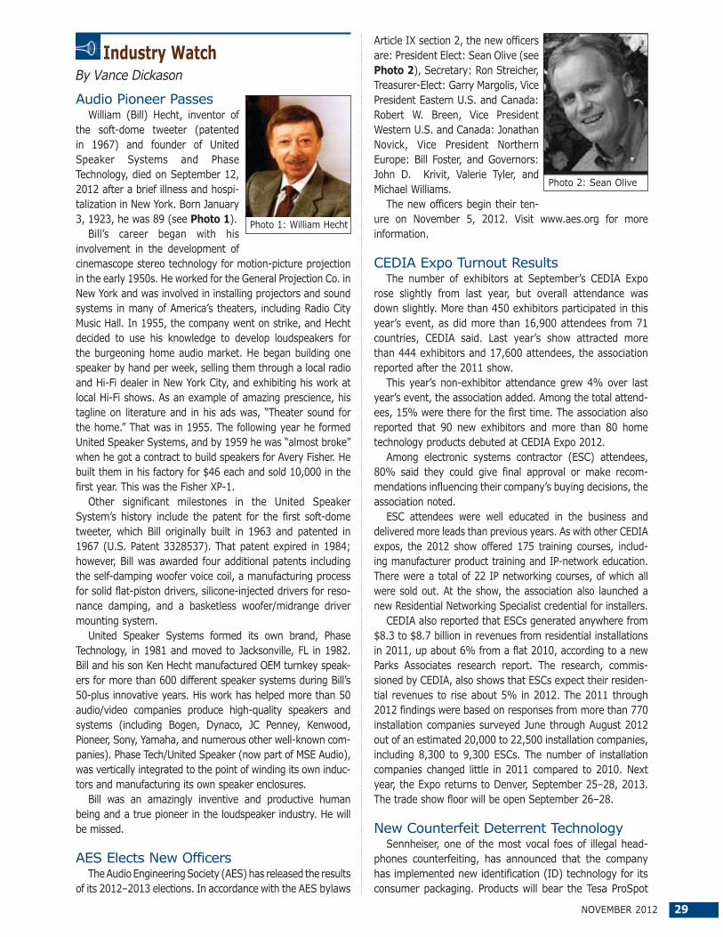
Article IX section 2, the new officers are: President Elect: Sean Olive (see Photo 2), Secretary: Ron Streicher, Treasurer-Elect: Garry Margolis, Vice President Eastern U.S. and Canada: Robert W. Breen, Vice President Western U.S. and Canada: Jonathan Novick, Vice President Northern Europe: Bill Foster, and Governors: John D. Krivit, Valerie Tyler, and Michael Williams.
The new officers begin their ten-ure on November 5, 2012. Visit www.aes.org for more information.
CEDIA Expo Turnout Results The number of exhibitors at September’s CEDIA Expo
rose slightly from last year, but overall attendance was down slightly. More than 450 exhibitors participated in this year’s event, as did more than 16,900 attendees from 71 countries, CEDIA said. Last year’s show attracted more than 444 exhibitors and 17,600 attendees, the association reported after the 2011 show.
This year’s non-exhibitor attendance grew 4% over last year’s event, the association added. Among the total attend-ees, 15% were there for the first time. The association also reported that 90 new exhibitors and more than 80 home technology products debuted at CEDIA Expo 2012.
Among electronic systems contractor (ESC) attendees, 80% said they could give final approval or make recom-mendations influencing their company’s buying decisions, the association noted.
ESC attendees were well educated in the business and delivered more leads than previous years. As with other CEDIA expos, the 2012 show offered 175 training courses, includ-ing manufacturer product training and IP-network education. There were a total of 22 IP networking courses, of which all were sold out. At the show, the association also launched a new Residential Networking Specialist credential for installers.
CEDIA also reported that ESCs generated anywhere from $8.3 to $8.7 billion in revenues from residential installations in 2011, up about 6% from a flat 2010, according to a new Parks Associates research report. The research, commis-sioned by CEDIA, also shows that ESCs expect their residen-tial revenues to rise about 5% in 2012. The 2011 through 2012 findings were based on responses from more than 770 installation companies surveyed June through August 2012 out of an estimated 20,000 to 22,500 installation companies, including 8,300 to 9,300 ESCs. The number of installation companies changed little in 2011 compared to 2010. Next year, the Expo returns to Denver, September 25–28, 2013. The trade show floor will be open September 26–28.
New Counterfeit Deterrent TechnologySennheiser, one of the most vocal foes of illegal head-
phones counterfeiting, has announced that the company has implemented new identification (ID) technology for its consumer packaging. Products will bear the Tesa ProSpot
Audio Pioneer PassesWilliam (Bill) Hecht, inventor of
the soft-dome tweeter (patented in 1967) and founder of United Speaker Systems and Phase Technology, died on September 12, 2012 after a brief illness and hospi-talization in New York. Born January 3, 1923, he was 89 (see Photo 1).
Bill’s career began with his involvement in the development of cinemascope stereo technology for motion-picture projection in the early 1950s. He worked for the General Projection Co. in New York and was involved in installing projectors and sound systems in many of America’s theaters, including Radio City Music Hall. In 1955, the company went on strike, and Hecht decided to use his knowledge to develop loudspeakers for the burgeoning home audio market. He began building one speaker by hand per week, selling them through a local radio and Hi-Fi dealer in New York City, and exhibiting his work at local Hi-Fi shows. As an example of amazing prescience, his tagline on literature and in his ads was, “Theater sound for the home.” That was in 1955. The following year he formed United Speaker Systems, and by 1959 he was “almost broke” when he got a contract to build speakers for Avery Fisher. He built them in his factory for $46 each and sold 10,000 in the first year. This was the Fisher XP-1.
Other significant milestones in the United Speaker System’s history include the patent for the first soft-dome tweeter, which Bill originally built in 1963 and patented in 1967 (U.S. Patent 3328537). That patent expired in 1984; however, Bill was awarded four additional patents including the self-damping woofer voice coil, a manufacturing process for solid flat-piston drivers, silicone-injected drivers for reso-nance damping, and a basketless woofer/midrange driver mounting system.
United Speaker Systems formed its own brand, Phase Technology, in 1981 and moved to Jacksonville, FL in 1982. Bill and his son Ken Hecht manufactured OEM turnkey speak-ers for more than 600 different speaker systems during Bill’s 50-plus innovative years. His work has helped more than 50 audio/video companies produce high-quality speakers and systems (including Bogen, Dynaco, JC Penney, Kenwood, Pioneer, Sony, Yamaha, and numerous other well-known com-panies). Phase Tech/United Speaker (now part of MSE Audio), was vertically integrated to the point of winding its own induc-tors and manufacturing its own speaker enclosures.
Bill was an amazingly inventive and productive human being and a true pioneer in the loudspeaker industry. He will be missed.
AES Elects New OfficersThe Audio Engineering Society (AES) has released the results
of its 2012–2013 elections. In accordance with the AES bylaws
Industry Watch
Photo 1: William Hecht
Photo 2: Sean Olive
By Vance Dickason
30 VOICE COIL
label, which has visible and invisible characteristics to ensure authenticity. Sennheiser said the label shows up in different colors under direct light, and the last digit of the security code is repeated in an enlarged format, enabling consumers to verify it at the company’s website. Consumers will also be able to scan the quick response (QR) code to check its authenticity.
Listen Moves Office, Hires Additional StaffListen, Inc. moved to a new custom-designed
8,000-ft2 office. The facility offers additional manu-facturing space for new employees and provides more storage for incoming components and finished goods. A large test and listening room offers space to display and simultaneously use several test setups; increased offices will house additional employees; and small training classes can be held in the new, spacious con-ference room.
Listen also hired three new employees this past summer. Mark Edelsward joined Listen in June as VP International sales. He is based in the northwest and will manage Listen’s international business as well as some West Coast accounts. Ritesh Banka, a recent Colorado State University master’s graduate who interned at Listen, joined the programming team. Finally, industry veteran Steve Tatarunis joined the customer support team, bringing with him more than 30 years of experience in transducer design and test.
2013 NAMM ShowThe National Association
of Music Merchants (NAMM) announced several upgrades and improvements prior to the opening of the 2013 NAMM Show opening in Anaheim, CA, January 24–27, 2013. To provide more space in the convention center, registration will move from the lobby to surrounding hotels. Extending the show to the outer glass doors opens entrances to the halls, and enables fewer ID checks once inside the convention center. The open lobby will also play host to an exclusive member center, a digital media hub, new product showcases, and more.
Lighting, touring, and sound will take center stage in The Venue, located in the convention center’s arena, which offers dimmed overhead lighting and tall ceilings. The new Grand Plaza is undergoing construction, but it will be completed in time for the NAMM Show. The plaza, which runs between the Hilton and Marriott and leads to the Anaheim Convention Center’s main entrance, will include an outdoor stage for live music throughout the day and a place for members to network.
Registration opened in October. Exhibit space is still avail-able for the 2013 event. NAMM member hotel bookings opened on October 3. Non-members can book rooms for the show beginning November 14. For more information on the NAMM Show 2013, visit www.namm.org/thenammshow/2013. VC
The NAMM Show logo
ACO Pacific, Inc. 2604 Read Ave., Belmont, CA 94002, USA
Tel: 650-595-8588 Fax: 650-591-2891www.acopacific.com [email protected] Begins With ACO™