July 2013 NASA/TM2013-218021/Volume I NESC-RP-12-00824 Independent Assessment of Instrumentation for ISS On-Orbit NDE Eric I Madaras/NESC Langley Research Center, Hampton, Virginia https://ntrs.nasa.gov/search.jsp?R=20140000802 2018-06-23T11:37:23+00:00Z
Transcript
July 2013
NASA/TM 2013-218021/Volume I NESC-RP-12-00824
Independent Assessment of Instrumentation for ISS On-Orbit NDE Eric I Madaras/NESC Langley Research Center, Hampton, Virginia
Since its founding, NASA has been dedicated to the advancement of aeronautics and space science. The NASA scientific and technical information (STI) program plays a key part in helping NASA maintain this important role.
The NASA STI program operates under the auspices of the Agency Chief Information Officer. It collects, organizes, provides for archiving, and disseminates NASA’s STI. The NASA STI program provides access to the NASA Aeronautics and Space Database and its public interface, the NASA Technical Report Server, thus providing one of the largest collections of aeronautical and space science STI in the world. Results are published in both non-NASA channels and by NASA in the NASA STI Report Series, which includes the following report types:
TECHNICAL PUBLICATION. Reports of
completed research or a major significant phase of research that present the results of NASA Programs and include extensive data or theoretical analysis. Includes compilations of significant scientific and technical data and information deemed to be of continuing reference value. NASA counterpart of peer-reviewed formal professional papers, but having less stringent limitations on manuscript length and extent of graphic presentations.
TECHNICAL MEMORANDUM. Scientific
and technical findings that are preliminary or of specialized interest, e.g., quick release reports, working papers, and bibliographies that contain minimal annotation. Does not contain extensive analysis.
CONTRACTOR REPORT. Scientific and
technical findings by NASA-sponsored contractors and grantees.
CONFERENCE PUBLICATION.
Collected papers from scientific and technical conferences, symposia, seminars, or other meetings sponsored or co-sponsored by NASA.
SPECIAL PUBLICATION. Scientific,
technical, or historical information from NASA programs, projects, and missions, often concerned with subjects having substantial public interest.
TECHNICAL TRANSLATION.
English-language translations of foreign scientific and technical material pertinent to NASA’s mission.
Specialized services also include organizing and publishing research results, distributing specialized research announcements and feeds, providing information desk and personal search support, and enabling data exchange services. For more information about the NASA STI program, see the following: Access the NASA STI program home page
at http://www.sti.nasa.gov E-mail your question to [email protected]
Fax your question to the NASA STI
Information Desk at 443-757-5803 Phone the NASA STI Information Desk at
443-757-5802 Write to:
STI Information Desk NASA Center for AeroSpace Information 7115 Standard Drive Hanover, MD 21076-1320
National Aeronautics and Space Administration Langley Research Center Hampton, Virginia 23681-2199
July 2013
NASA/TM 2013-218021/Volume I NESC-RP-12-00824
Independent Assessment of Instrumentation for ISS On-Orbit NDE Eric I Madaras/NESC Langley Research Center, Hampton, Virginia
Available from:
NASA Center for AeroSpace Information 7115 Standard Drive
Hanover, MD 21076-1320 443-757-5802
Acknowledgments
Significant Contributors to this report were:
William Prosser LaRC Ajay Koshti JSC Miles Skow KSC Dave Stanley JSC/Jacobs Technology Bruce Blazine JSC/United Space Alliance Dan Perri JSC/Jacobs Technology Chris Sinclair JSC/Jacobs Technology Bert Young JSC/United Space Alliance Todd Hong JSC Kornel Nagy JSC George Studor JSC
The use of trademarks or names of manufacturers in the report is for accurate reporting and does not constitute an official endorsement, either expressed or implied, of such products or manufacturers by the National Aeronautics and Space Administration.
NASA Engineering and Safety Center Technical Assessment Report
Document #:
NESC-RP-12-00824
Version:
1.0
Title:
Independent Assessment of Instrumentation for ISS On-orbit NDE
Page #:
1 of 96
NESC Request No.: TI-12-00824, Volume I
Independent Assessment of Instrumentation for International Space Station (ISS) On-orbit
Nondestructive Evaluation (NDE)
May 16, 2013
NASA Engineering and Safety CenterTechnical Assessment Report
Document #:
NESC-RP-12-00824
Version:
1.0
Title:
Independent Assessment of Instrumentation for ISS On-orbit NDE
Page #:
2 of 96
NESC Request No.: TI-12-00824, Volume I
Report Approval and Revision History
NOTE: This document was approved at the May 16, 2013, NRB. This document was submitted to the NESC Director on June 6, 2013, for configuration control.
Approved:
NESC Director Date
Version Description of Revision Office of Primary Responsibility Effective Date
1.0 Initial Release Dr. William Prosser, NASA Technical Fellow for Nondestructive Evaluation, LaRC
5/16/13
NASA Engineering and Safety Center Technical Assessment Report
Document #:
NESC-RP-12-00824
Version:
1.0
Title:
Independent Assessment of Instrumentation for ISS On-orbit NDE
Page #:
3 of 96
NESC Request No.: TI-12-00824, Volume I
Table of Contents Technical Assessment Report 1.0 Notification and Authorization ..................................................................................................... 7 2.0 Signature Page ................................................................................................................................ 8 3.0 Team List ........................................................................................................................................ 9 4.0 Executive Summary ..................................................................................................................... 10 5.0 Assessment Plan ........................................................................................................................... 12 6.0 Problem Description and Proposed Solutions ........................................................................... 13
6.1 Problem Description ......................................................................................................... 13 6.2 Proposed Solution ............................................................................................................. 14 6.2.1 Finalize Evaluation Criteria for Down-selecting Best Available NDE Instrumentation .. 15 6.2.2 Select NDE Systems to Evaluate ...................................................................................... 16 6.2.3 Finalize Design and Manufacture of Set of Appropriate Physical Standards on
which to Test ..................................................................................................................... 17 6.2.4 Develop Procedures for Evaluating NDE Instrumentation to Lead to Down-selecting
the Best Available Instrument ........................................................................................... 17 6.2.5 Perform Testing with Instrument Systems ........................................................................ 18 6.2.6 Obtain Astronaut Office, Mission Operations Directorate (MOD), and Operations
Support Office (OSO) Qualitative Assessments and Inputs Regarding On-orbit NDE Equipment Interface and Operational Appropriateness .................................................... 18
6.2.7 Produce an Engineering Assessment of CIRD COTS Hardware Compatibility for Top Choices.............................................................................................................................. 18
6.2.8 Down Select Instrument .................................................................................................... 19 6.2.9 Write Final Report ............................................................................................................ 19
7.0 Analysis ......................................................................................................................................... 19 7.1 NDE Assessments ............................................................................................................. 19 7.1.1 ISS PWRK System ........................................................................................................... 20 7.1.2 Test Standards and Samples.............................................................................................. 22 7.1.3 Testing Configurations ..................................................................................................... 32 7.1.4 Olympus Omniscan MX UT ............................................................................................. 35 7.1.5 Sonatest Veo ..................................................................................................................... 43 7.1.6 GE Phasor XS ................................................................................................................... 53 7.1.7 Olympus Omniscan MX EC ............................................................................................. 57 7.1.8 UniWest 454A ECS3 ........................................................................................................ 60 7.1.9 Jentek GridStation ............................................................................................................. 65 7.1.10 NDE Instrument Test Assessment .................................................................................... 69 7.2 Operations/Astronaut Assessments ................................................................................... 74 7.2.1 Astronauts ......................................................................................................................... 74 7.2.2 Operations ......................................................................................................................... 77 7.2.3 Operations/Astronaut Scoring ........................................................................................... 78 7.3 Engineering Assessments ................................................................................................. 79 7.3.1 EMI Radiated Emissions and EMI Susceptibility............................................................. 79
NASA Engineering and Safety Center Technical Assessment Report
Document #:
NESC-RP-12-00824
Version:
1.0
Title:
Independent Assessment of Instrumentation for ISS On-orbit NDE
9.0 Alternate Viewpoints ................................................................................................................... 92 10.0 Other Deliverables ....................................................................................................................... 92 11.0 Lessons Learned ........................................................................................................................... 92 12.0 Recommendations for NASA Standards and Specifications .................................................... 92 13.0 Definition of Terms ...................................................................................................................... 92 14.0 Acronyms List .............................................................................................................................. 93 15.0 References ..................................................................................................................................... 95 16.0 Volume II: Appendices (separate volume)................................................................................. 95
List of Figures Figure 7.1-1. PWRK Tape Patch Mock-up ............................................................................................ 21 Figure 7.1-2. PWRK Plate Patch ............................................................................................................ 22 Figure 7.1-3. FGB and SM Style Rib-stiffened Walls ............................................................................ 23 Figure 7.1-4. Standard 4, with the Same Manufactured Flaw Pattern as in Standard 2 ......................... 24 Figure 7.1-5. Standard 3, with Partial Through-the-wall Holes Organized as Three Rings around
1-inch, Large Flat-bottom Partial Through-hole at Plate Center ...................................... 25 Figure 7.1-6. Standard 5, with Partial Through-the-wall Holes Organized as Three Rings around
1-inch Large Through-hole at Plate Center ...................................................................... 25 Figure 7.1-7. Standard 6A, which has the Same Manufactured Flaw Pattern as Created in
Standard 2 ......................................................................................................................... 26 Figure 7.1-8. Standard 7B, which has the Same Manufactured Flaw Pattern as Created in
Standard 2 ......................................................................................................................... 27 Figure 7.1-9. Backside of Impact Plate 186 ........................................................................................... 28 Figure 7.1-10. Backside of Impact Plate 1900, a 1/8-inch-thick Panel .................................................... 29 Figure 7.1-11. Backside of Impact Plate 1907 ......................................................................................... 30 Figure 7.1-12. Backside of Impact Plate T3 ............................................................................................. 31 Figure 7.1-13. Backside of Impact Plate 243, which Represents FGB Wall and was Impacted with a
Hypervelocity Projectile ................................................................................................... 32 Figure 7.1-14. Phased Array-angle Beam Block Probe Geometry for Scanning under a Patch Repair ... 33
NASA Engineering and Safety Center Technical Assessment Report
Document #:
NESC-RP-12-00824
Version:
1.0
Title:
Independent Assessment of Instrumentation for ISS On-orbit NDE
Figure 7.1-16. EC Probe Geometry for Scanning near Patch Repair ....................................................... 35 Figure 7.1-17. Olympus Omniscan MX UT Model ................................................................................. 36 Figure 7.1-18. Angle-beam Scans of Standard 2 ...................................................................................... 37 Figure 7.1-19. Angle-beam Scans of Standard 3 ...................................................................................... 38 Figure 7.1-20. Composite Image from Five Zero Beam C-scans of Standard 3 ...................................... 39 Figure 7.1-21. Angle Beam B-scan Image of Impact Plate 186 without Repair ...................................... 40 Figure 7.1-22. Angle-beam B-Scan Image of Impact Plate 1907 without Repair .................................... 41 Figure 7.1-23. Angle-beam B-Scan Image of Impact Plate 1900 without Repair .................................... 42 Figure 7.1-24. Front Panel of Sonatest Veo System ................................................................................. 44 Figure 7.1-25. Top-scan Images of Standard 2 ......................................................................................... 46 Figure 7.1-26. Views of Standard 3 .......................................................................................................... 48 Figure 7.1-27. Top-scan Images from a Curved Sample .......................................................................... 49 Figure 7.1-28. Angle Beam Top-scan Images of Impact Plate 186 .......................................................... 49 Figure 7.1-29. Impact Plate 1900 with Plate Patch .................................................................................. 50 Figure 7.1-30. Top-scan Image of Impact Plate T3 .................................................................................. 51 Figure 7.1-31. Impact Plate 243 ............................................................................................................... 52 Figure 7.1-32. GE Phasor XS System ...................................................................................................... 54 Figure 7.1-33. A B-scan Image of Standard 3 showing the Results of Imaging the Multisite Partial
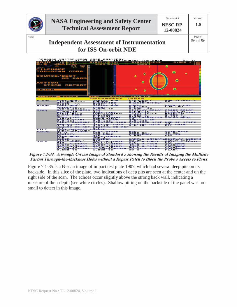
Through-the-thickness Holes ............................................................................................ 55 Figure 7.1-34. A 0-angle C-scan Image of Standard 5 showing the Results of Imaging the Multisite
Partial Through-the-thickness Holes without a Repair Patch to Block the Probe's Access to Flaws ................................................................................................................ 56
Figure 7.1-35. A B-scan Image of Impact Test Plate 1907 showing the Results of Imaging the Pits Through-the-Thickness of the Plate without a Repair Patch ............................................ 57
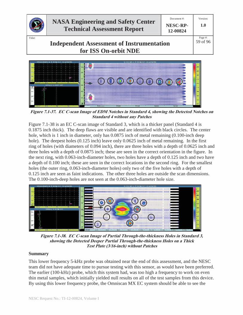
Figure 7.1-36. EC C-scan Images of Partial Through-the-thickness Holes in Standard 4 ....................... 58 Figure 7.1-37. EC C-scan Image of EDM Notches in Standard 4, showing the Detected Notches on
Standard 4 without any Patches ........................................................................................ 59 Figure 7.1-38. EC C-scan Image of Partial Through-the-thickness Holes in Standard 3, showing
the Detected Deeper Partial Through-the-thickness Holes on a Thick Test Plate (3/16-inch) without Patches .............................................................................................. 59
Figure 7.1-39. UniWest 454A ECS3 System with Laptop Computer, which Records Data and Displays Images ................................................................................................................ 61
Figure 7.1-40. EC C-scan Images of EDM Notches in Standard 1B, the FGB Patterned Test Plate........................................................................................................................... 62
Figure 7.1-41. EC C-scan Images of Partial Through-the-thickness Holes in Standard 1B, the FGB Patterned Test Plate .......................................................................................................... 63
NASA Engineering and Safety Center Technical Assessment Report
Document #:
NESC-RP-12-00824
Version:
1.0
Title:
Independent Assessment of Instrumentation for ISS On-orbit NDE
Page #:
6 of 96
NESC Request No.: TI-12-00824, Volume I
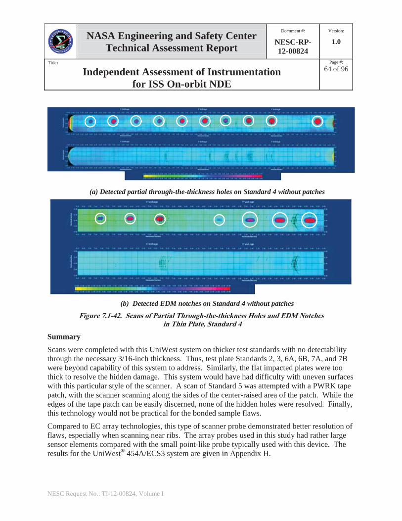
Figure 7.1-42. Scans of Partial Through-the-thickness Holes and EDM Notches in Thin Plate, Standard 4 ......................................................................................................................... 64
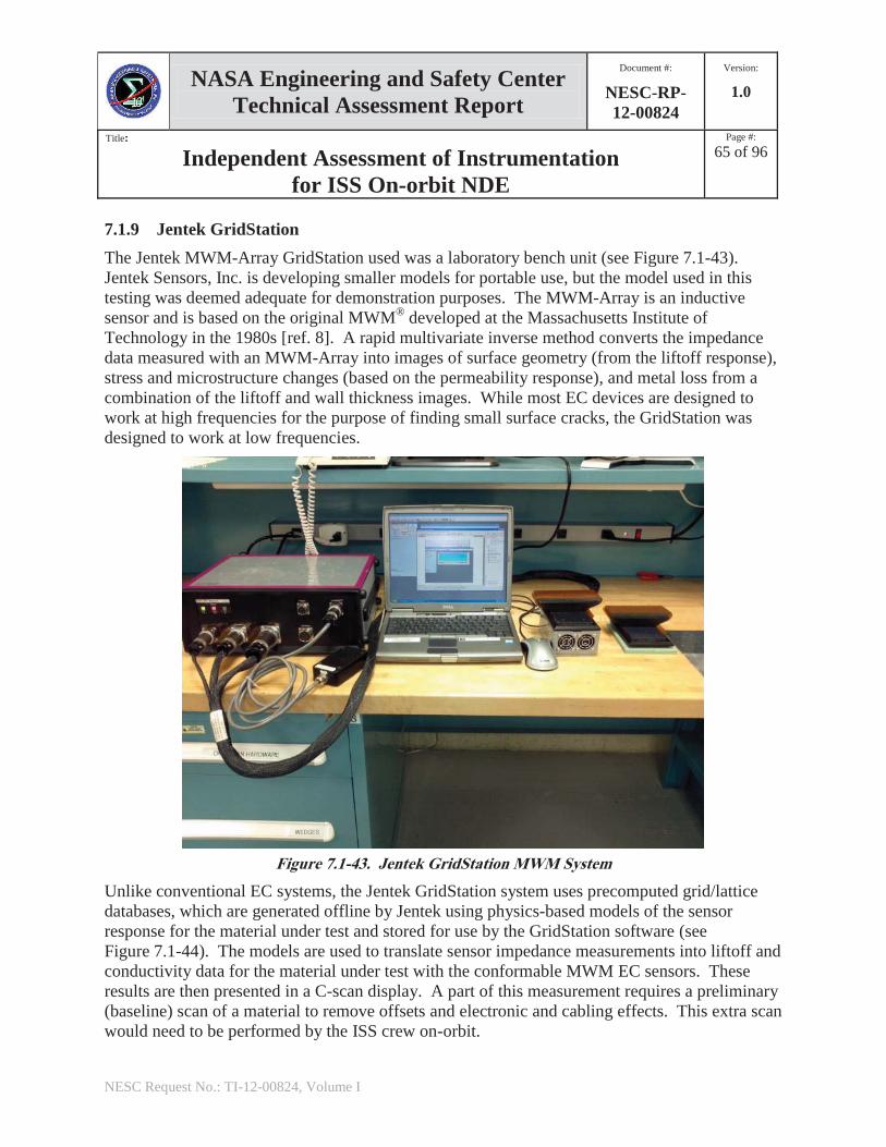
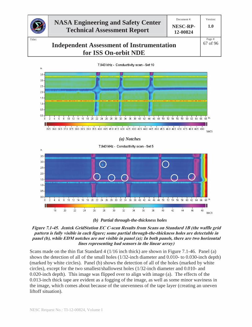
Figure 7.1-43. Jentek GridStation MWM System .................................................................................... 65 Figure 7.1-44. Signal Processing Steps Used in Jentek GridStation MWM System ................................ 66 Figure 7.1-45. Jentek GridStation EC C-scan Results from Scans on Standard 1B ................................. 67 Figure 7.1-46. Jentek GridStation Results from Scans on Standard 4 of Partial Through-the-thickness
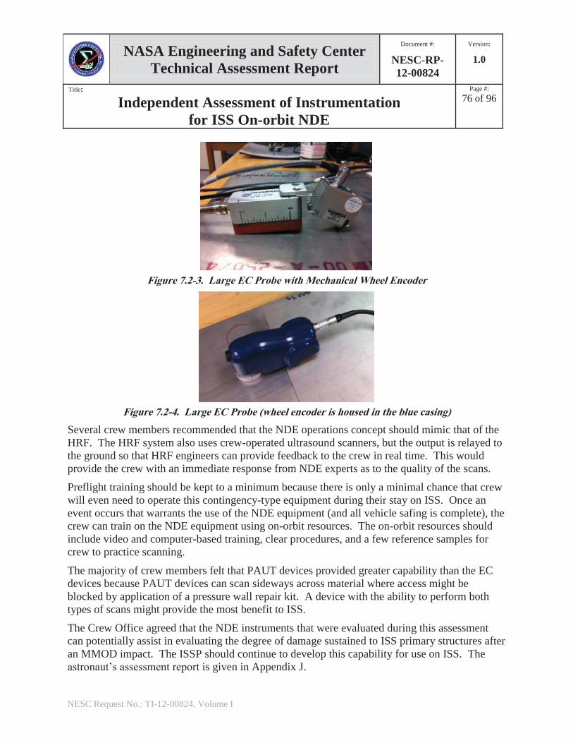
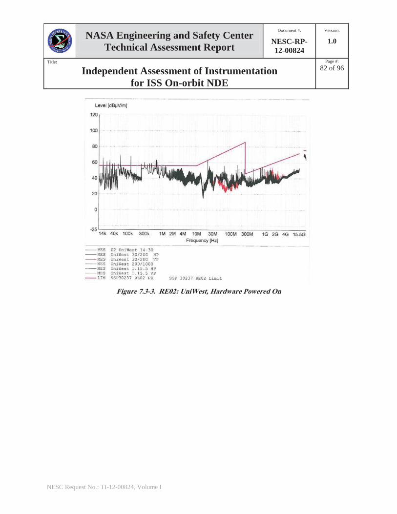
Holes ................................................................................................................................. 68 Figure 7.1-47. Jentek GridStation Results from Scans on Standard 4 of EDM Notches ......................... 69 Figure 7.2-1. Scanning using a Metal Ruler as a Guide ......................................................................... 75 Figure 7.2-2. Ultrasound Array with Mechanical Wheel Encoder ......................................................... 75 Figure 7.2-3. Large EC Probe with Mechanical Wheel Encoder ........................................................... 76 Figure 7.2-4. Large EC Probe ................................................................................................................. 76 Figure 7.3-1. RE02: OmniScan MX, Hardware Powered On ................................................................ 80 Figure 7.3-2. RE02: Sonatest VEO, Hardware Powered On .................................................................. 81 Figure 7.3-3. RE02: UniWest, Hardware Powered On .......................................................................... 82 Figure 7.3-4. RE02: UniWest, AC Power On, EUT Off ........................................................................ 83 Figure 7.3-5. Thermal Analysis Results ................................................................................................. 86
List of Tables
Table 7.1-1. Olympus Omniscan MX UT NDE Assessment Scoring .................................................. 70 Table 7.1-2. Sonatest Veo NDE Assessment Scoring ........................................................................... 70 Table 7.1-3. GE Phasor XS NDE Assessment Scoring ......................................................................... 71 Table 7.1-4. Olympus Omniscan MX EC NDE Assessment Scoring ................................................... 71 Table 7.1-5. UniWest 454A ECS3 NDE Assessment Scoring .............................................................. 72 Table 7.1-6. Jentek GridStation NDE Assessment Scoring .................................................................. 72 Table 7.1-7. Summary NDE Assessment Scores .................................................................................. 73 Table 7.2-1. Summary Operation Assessment Score ............................................................................ 78 Table 7.3-1. Summary Engineering Assessment Score ........................................................................ 88 Table 7.4-1. Final Summary Assessment Scores .................................................................................. 89
NASA Engineering and Safety Center Technical Assessment Report
Document #:
NESC-RP-12-00824
Version:
1.0
Title:
Independent Assessment of Instrumentation for ISS On-orbit NDE
Page #:
7 of 96
NESC Request No.: TI-12-00824, Volume I
Technical Assessment Report
1.0 Notification and Authorization Dr. Kornel Nagy, International Space Station (ISS) Structural and Mechanical Systems Manager, requested that the NASA Engineering and Safety Center (NESC) provide a quantitative assessment of commercially available nondestructive evaluation (NDE) instruments for potential application to the ISS. This work supports risk mitigation as outlined in the ISS Integrated Risk Management Application (IRMA) Watch Item #4669, which addresses the requirement for structural integrity after an ISS pressure wall leak in the event of a penetration due to micrometeoroid or orbital debris impact [ref. 1].
Dr. Eric Madaras of the Langley Research Center (LaRC) was assigned to lead this assessment. The NESC Review Board (NRB) approved the assessment plan on August 9, 2012.
The key stakeholders for this assessment include, for the ISS Program (ISSP): Kevin Window, ISS Vehicle Manager; Kornel Nagy, ISS Structure and Mechanisms Systems Manager; and Bill McCann, The Boeing Company’s Mechanical Structural Evaluation and Robotics Systems Manager.
NASA Engineering and Safety CenterTechnical Assessment Report
Document #:
NESC-RP-12-00824
Version:
1.0
Title:
Independent Assessment of Instrumentation for ISS On-orbit NDE
Page #:
8 of 96
NESC Request No.: TI-12-00824, Volume I
2.0 Signature Page
Submitted by:
Dr. Eric I. Madaras Date
Significant Contributors:
Dr. William H. Prosser Date Dr. Ajay Koshti Date
Mr. David M. Stanley Date Mr. Miles Skow Date
Mr. Bruce Blazine Date Mr. Bert Young Date
Mr. Daniel P. Perri Date r. Christopher M. Sinclair Date
Mr. Todd C. Hong Date Date
Mr. George F. Studor Date
Signatories declare the findings and observations compiled in the report are factually based from data extracted from Program/project documents, contractor reports, and open literature, and/or generated from independently conducted tests, analysis, and inspections.
NASA Engineering and Safety Center Technical Assessment Report
Document #:
NESC-RP-12-00824
Version:
1.0
Title:
Independent Assessment of Instrumentation for ISS On-orbit NDE
Page #:
9 of 96
NESC Request No.: TI-12-00824, Volume I
3.0 Team List
Name Discipline Organization Core Team William Prosser NASA Technical Fellow for NDE LaRC Eric Madaras NESC Lead LaRC Ajay Koshti NDE Lead JSC Miles Skow NDE KSC Dave Stanley NDE JSC/Jacobs Technology Bruce Blazine Astronaut Support/Operations Lead JSC/United Space Alliance Dan Perri Operations JSC/Jacobs Technology Chris Sinclair Operations JSC/Jacobs Technology Bert Young Operations JSC/United Space Alliance Todd Hong Engineering Lead JSC Issa Zaid Engineering JSC/Jacobs Technology Kornel Nagy Structures and Mechanics Lead JSC Russell Graves Structures and Mechanics The Boeing Company Raymond Patin Structures and Mechanics JSC George Studor Structures and Mechanics JSC Eric Christiansen MMOD Damage Lead JSC Serena Aunon Astronaut JSC Mike Fincke Astronaut JSC Dorothy Metcalf-Linenburger Astronaut JSC Don Pettit Astronaut JSC Shannon Walker Astronaut JSC Kimiya Yui Astronaut JSC Roy Savage MTSO Program Analyst LaRC Administrative Support Linda Burgess Planning and Control Analyst LaRC/AMA Jonay Campbell Technical Writer LaRC/NG Terri Derby Project Coordinator LaRC/AMA
NASA Engineering and Safety Center Technical Assessment Report
Document #:
NESC-RP-12-00824
Version:
1.0
Title:
Independent Assessment of Instrumentation for ISS On-orbit NDE
Page #:
10 of 96
NESC Request No.: TI-12-00824, Volume I
4.0 Executive Summary Leaks through the International Space Station (ISS) pressure wall as a result of micrometeoroid and orbital debris (MMOD) impact damage are mitigated with patches, provided that the leak rate is not so high that the module must be isolated and allowed to depressurize. However, the patch repair process is only a pressure repair and is not intended as a structural repair. Should such damage occur and a pressure patch installed, the ISS Program (ISSP) then needs to assess the state of the structural integrity of the damaged pressure wall to ensure continued safe ISS operations of the vehicle. The ability to obtain measurements of the structural state of a damaged pressure wall so that structural engineers can assess structural integrity and remaining life is part of the process to reduce risks as documented by the ISSP in ISS Risk Management Application (IRMA), Watch Item #4669 [ref. 1].
One approach under ISSP consideration to implement this risk reduction process is to adapt a commercially available nondestructive evaluation (NDE) field portable instrument for intravehicular activity (IVA) operation aboard the ISS. The NASA Engineering and Safety Center (NESC) was requested by the ISSP to perform an independent assessment of commercially available NDE portable instruments and recommend the best instrument that could be adapted for this application. Key aspects to be addressed in this assessment were (1) the instrument’s ability to nondestructively characterize pressure wall damage within ISS operational constraints, (2) the operational ease of use by ISS crew in a zero-G environment, (3) the operational impact of such instrumentation (maintenance and support) on the ISS, and (4) the identification of any necessary modifications that would be required for certification of the instrument for operations aboard the ISS.
A team of NDE, ISS operations, and space hardware certification experts, as well as astronauts, were assembled to perform this NDE instrumentation assessment. MMOD and ISS structural integrity experts were solicited to provide additional guidance. The NESC team selected six instruments for evaluation. These instruments were designed for portable field operations and are generally viewed by the NDE community as being robust and simple to use. Three devices were phased array ultrasonic test (PAUT) measurement systems, and three devices were related to eddy current (EC) systems. The EC systems utilized either single-probe mechanical scanning systems or array sensors. The PAUT instruments evaluated were the Olympus Omniscan MX UT (Ultrasonic Test), the Sonatest Veo, and the General Electric (GE)® PhasorTM; the EC instruments were the Olympus Omniscan MX EC array, the UniWest® 454A ECS3 mechanical scanner, and the Jentek® GridStation® Meandering Winding Magnetometer (MWM)® Array.
This assessment resulted in 15 findings, which are listed in Section 8.1. The primary finding was that all of the NDE systems were sensitive to detecting hidden structures such as isogrid webs, which could be useful for identifying structural orientation in images, but at the same time those structures affected the instrument’s ability to detect damage directly adjacent to the isogrid web under a pressure wall repair kit (PWRK) patch. It was found that PAUT systems were more
NASA Engineering and Safety Center Technical Assessment Report
Document #:
NESC-RP-12-00824
Version:
1.0
Title:
Independent Assessment of Instrumentation for ISS On-orbit NDE
Page #:
11 of 96
NESC Request No.: TI-12-00824, Volume I
capable than EC array/scanner systems in detecting and assessing damage from manufactured test plates and simulated MMOD impacts with the PWRK patches. The Sonatest Veo used an imaging process called "Top-scan," which saves all of the data from the different inspection angles, which could be advantageous for subsequent analysis of the results on the ground in the event that the angle initially selected was not optimum. The ISS crew were able to quickly assemble and operate each of the instruments evaluated using only simple one-page procedures and without additional training. All of the scanning systems utilized spring-loaded position encoders, except for the UniWest system. In the zero-G environment, these spring-loaded devices will require a reaction force to keep the sensor in contact with the part undergoing inspection. In addition, a level of force was required to hold the sensor in contact with the pressure wall. To react against those forces necessary to perform scans and operate the NDE equipment in a zero-G environment, the astronauts identified the need to provide a restraint during inspection activities, as well as the need for the system to be operated with one hand only so that the other hand remains free to activate instrument buttons. The probes/scanning components of the assessed NDE instruments were currently too large to permit inspections underneath racks and fixed structures and behind panels. Although all of the instruments were deemed usable, several astronauts expressed a preference for the Sonatest Veo system because of its simpler operating controls and computer-human interface, plus the visual display made identification of flaws more intuitive (a Top-scan capability) for untrained personnel helping them to quickly assess the validity of a measurement. The Sonatest Veo and Olympus Omniscan MX UT (and MX2) PAUT systems had electromagnetic interference (EMI) emission exceedances. The information provided by the vendors regarding the materials contained in these instruments was incomplete. The Olympus Omniscan MX UT and Sonatest Veo systems exceeded thermal touch temperatures in a vacuum environment, although this is not a requirement for currently planned operational scenarios.
The assessment’s observations are found in Section 8.2. The primary observation was that the development of nonstandard methods and procedures will be required to enable quantitative measurements of damage under an ISS pressure repair patch. The use of the Human Research Facility (HRF) operations model for conducting body ultrasound could be used as a guide for the development of NDE on-orbit inspection operations procedures.
The NESC recommendations directed to the ISSP, in the event that a decision is made to utilize NDE instrumentation aboard the ISS to mitigate IRMA Risk 4669, were to select the Sonatest Veo PAUT system for development and certification for flight based on the findings; develop methods to enable ISS crew to apply reaction forces against scanning system spring-loaded encoders in a zero-G environment or identify alternative scanning system designs that do not require reaction forces; and develop compatible sensors and scanning system components to enable inspections over the maximum percentage of ISS module surface area.
NASA Engineering and Safety Center Technical Assessment Report
Document #:
NESC-RP-12-00824
Version:
1.0
Title:
Independent Assessment of Instrumentation for ISS On-orbit NDE
Page #:
12 of 96
NESC Request No.: TI-12-00824, Volume I
5.0 Assessment Plan The purpose of this assessment was to evaluate the commercial field portable NDE equipment that would best address the risk mitigation steps outlined in IRMA 4669, leading to the down selection of the most appropriate instrumentation for flight. This assessment reviewed ISS requirements that levy significant constraints on ISS on-orbit instrumentation and operations. During this assessment, several issues were considered, which included:
1. Will the instrument provide relevant information that structural engineers require for evaluating the complex nature of damage in the ISS pressure wall (e.g., crack lengths and directions, wall thinning, and wall deformation)?
2. Can the equipment properly function within constraints or interference from the local complexity of the structure and the interference caused by the presence of any pressure repair that is blocking direct access to the damaged area?
3. Would the user interface (UI) and functionality of the equipment be compatible with operational constraints, considering that the ISS crew will be untrained regarding the operation of the equipment? That is, can ISS crew perform the measurements and understand whether a quantitatively valid measurement has been made? Will the use and maintenance of the instrumentation require unrealistic time resources?
4. Is there a reasonable chance that the equipment will meet Common Interface Requirements Document (CIRD)-SSP 50835 for the ISS (e.g., electromagnetic emissions, battery constraints) without impractical reengineering?
The NESC team consisted of experts in NDE, ISS structural requirements, CIRD knowledge, and applicable flight operations. This assessment of NDE equipment to address these issues could directly lead to satisfying the requirements of the ISSP regarding how to address IRMA 4669. This assessment will be used as the basis for the generation of a change request (CR) to the ISS to support IRMA 4669, starting in fiscal year 2013.
In the original assessment plan, a fifth issue was identified to evaluate the equipment’s ability to reach and operate in areas with limited access, which exist in many of the areas of the ISS. That is, if a patch repair can be installed within a limited access area, then can the NDE equipment also reach and operate at that location? This question was not fully explored in this assessment. It quickly became apparent that all of the NDE systems would require modifications in order to fit behind racks and panels, if required, and that their scanning capabilities would need to be enhanced in order to make a practical system that could reach areas of concern behind racks and panels. For the ISS Vehicle Office, it seemed more efficient to first work, under a phase I effort, on manifesting an NDE system that could address 70 percent of the wall surface for the United States (U.S.) modules. For the Russian hardware, the percentage was closer to 30 percent, as much of the service module (SM) has fixed panels, making access more difficult.
NASA Engineering and Safety Center Technical Assessment Report
Document #:
NESC-RP-12-00824
Version:
1.0
Title:
Independent Assessment of Instrumentation for ISS On-orbit NDE
Page #:
13 of 96
NESC Request No.: TI-12-00824, Volume I
A phase II effort will be proposed to address the issues related to accessing the remaining 30 percent of the U.S. module walls and 70 percent of the Russian hardware. Evaluation and discussions with manufacturers’ representatives provided reasonable confidence that specialized probes could be fabricated and adapted to maximize the U.S. module inspection areas.
This assessment was separated into three components. One was an assessment of a set of commercial, portable instruments to see how well they could perform the required NDE testing on representative samples with the potential repair plates or tape patches that are currently certified for ISS use. For this part of the assessment, sets of instruments were selected, and various impacted test plates and test standard plates were manufactured or acquired. Testing processes were developed to allow testing in a manner that would be compatible with actual space operations. The second part of the assessment was to have astronauts and operations personnel evaluate the instruments from their knowledge of operations requirements and zero-G effects on-orbit using procedures developed by the first team. The third part was to perform engineering evaluations on the best systems to ensure that certification was feasible for those instruments. As a final step in the assessment, each of the systems under each of the three teams was individually ranked, and then an aggregate ranking was developed from which a down selection could be made.
6.0 Problem Description and Proposed Solutions 6.1 Problem Description There is a high risk of module damage/penetration from MMOD impact to the ISS over the life of the Program. At present, the current ISS prediction is that there is greater than a 33-percent probability of ISS penetration from MMOD over a 10-year period (see Appendix B [ref. 2]). MMOD debris threats have been changing as space junk collisions and recent antisatellite weapons testing create more debris and as additional modules are manifested. Although on-orbit leak repair kits are available for pressure loss mitigation, these kits do not address structural repair. The needed quantitative NDE damage assessment tools to support the evaluation and repair of structural damage are not on-orbit.
In 2011, at the ISS On-Orbit ISS Leak Detection and Repair Committee’s International Technical Interchange Meeting (TIM) in Moscow, Russia, the topic of structural repair after MMOD penetration was discussed. One of the points made at that meeting was the need to characterize the degree of damage and to certify any repair made. Typically, both of those needs would be met by NDE means. It was stated that commercial off-the-shelf (COTS) NDE equipment was at a state of development that it should be investigated for such purposes [ref. 3]. The information from that TIM was subsequently included in updated ISS IRMA Watch Item #4669 [ref. 1], a process whereby ISS risks are systematically addressed.
In 2012, a NASA team sought to develop a preliminary concept of operations for how NDE would be applied on-orbit to understand the requirements for NDE equipment. Generally, there
NASA Engineering and Safety Center Technical Assessment Report
Document #:
NESC-RP-12-00824
Version:
1.0
Title:
Independent Assessment of Instrumentation for ISS On-orbit NDE
Page #:
14 of 96
NESC Request No.: TI-12-00824, Volume I
are two conditions to consider. First, if the ISS should suffer a pressure wall penetration due to MMOD damage, which could be repaired with an IVA patch kit, then structural evaluation could be subsequently performed by IVA means. If a structural repair is required, then certification of the repair would also be performed by IVA means. Second, if a leak were too large to repair in a timely manner, the ISS crew would be forced to let the module decompress. Whether the repair was structural or pressure only, an extravehicular activity (EVA) repair would be required to allow the module to be repressurized. Depending on the nature of the repair, it is possible that certification of the repair could be accomplished via IVA means. In these cases, the NDE operations would be performed in a pressurized module and would not be operated under emergency conditions.
Once an understanding of the requirements was obtained, the NASA team investigated the types of instrumentation that would suit their needs. It became clear that an organized assessment of appropriate NDE instrumentation was required to address the varied needs outlined by the concept of operations, which lead to the request for an assessment by the NESC to determine which field portable NDE equipment would best address IRMA 4669.
6.2 Proposed Solution The assessment of the best instrument required that three areas of concern be evaluated. First, would an NDE instrument be able to make the needed measurements of the types of damage produced, given the constraints the repair might impose on the measurement process? This could include issues such as accessing the repaired wall, imaging a flaw with a repair seal in place, and imaging and quantifying complex damage. Second, would the ISS crew be able to perform the needed testing on-orbit under zero-G conditions? Note that standard NDE certified processes require a certified individual with demonstrated skills in applying a procedure be used for such a measurement. Generally, ISS crew members are not expected to be certified. There were also issues regarding how complex the system would be to assemble and operate on-orbit, how many crew members would be necessary to operate the system, and how much time the testing would require. How would an astronaut determine whether the measured data were adequate? How would the data be processed after the measurement and other operational issues? How would instrumentation be maintained on-orbit, including the issues of mass, volume, and storage needs? The third area of concern was the critical issue of certification for flight. The cost of instrumentation modifications could be prohibitive. Safety issues stemming from power, materials, and EMI would need to be investigated as a part of selecting a system for flight. Thus, three issues were the focus of this assessment: (1) the capability of the commercial field portable equipment to make relevant measurements, (2) the impacts of the instrument on operations/crew, and (3) flight certification considerations. Each of these issues was evaluated separately, and then an integrated assessment was made to determine whether a single device could achieve the required ISS applications.
The NESC team determined that the main focus of the devices should be centered on PAUT and EC techniques, as these are mature technologies and are already the basis for certified methods
NASA Engineering and Safety Center Technical Assessment Report
Document #:
NESC-RP-12-00824
Version:
1.0
Title:
Independent Assessment of Instrumentation for ISS On-orbit NDE
Page #:
15 of 96
NESC Request No.: TI-12-00824, Volume I
listed in NASA-STD-5009, “Nondestructive Evaluation Requirements for Fracture Critical Metallic Components” [ref. 4]. Other methods such as radiography, which require two-sided operations and would involve EVA efforts, were not considered because of concept-of-operations violations. Similarly, methods such as penetrant and thermography fail to detect cracks or damage on the far side of the wall and under the PWRK. Novel and development devices such as X-ray backscatter were not considered because the current state of development was not mature in areas such as operations, compactness, power, size, and safety. Thus, the tasks required for this assessment were as follows.
6.2.1 Finalize Evaluation Criteria for Down-selecting Best Available NDE Instrumentation
Each of the three assessment groups generated an evaluation table to score the various instruments with regard to their specific concerns for on-orbit operations. In principle, the assessment of NDE capabilities evaluated the ability of a system to accomplish the test required regardless of cost—if the system could not accomplish the required task, it did not matter what the other assessments indicated, the method was not considered.
The other assessments evaluate various costs of implementation. The engineering assessment considered the cost before deployment. Low scores in this category typically indicated the need for expensive modifications. The on-orbit operations assessment considered continuing operational costs. A low score here suggested high costs in manpower and support. There may sometimes be an inverse correlation between the operations cost and the engineering cost since a cheaper device might be chosen and deployed only to be difficult to work with on-orbit, thereby increasing the operations budget. The reverse can also be true—by spending more on engineering, future operations might be simplified and less expensive. It was necessary that this assessment capture these features correctly.
6.2.1.1 Assess NDE Capabilities Each device was to be scored against its ability to measure flaws in test plates with manufactured and realistic flaws under conditions of unrepaired or repaired with one of two PWRK repairs: a tape repair patch and a hard-plate “o-ring” sealing repair. In the case of bonded repairs, no PWRK patch would be in place. The scoring was grouped into three values. A value of 2 indicated that the system was able to measure all or nearly all of the flaw indications present. A value of 1 indicated that the system was able to detect the largest flaws but might not have the signal to noise to detect many of the smaller or minor flaws. A value of 0 indicated that the system was unable to give any measurable indications in the area of interest. The test samples were grouped into three groups: plates with manufactured flaws such as electric discharge machining (EDM) notches or partial through-the-thickness holes in aluminum plates; plates impacted by hypervelocity projectiles displaying pitting, cracks, holes, and deformation; and plates with bond-line flaws. Each of these groups of samples was averaged separately over all of the test articles in that group: manufacture flaw sample group, hypervelocity damage group, and the bonded plate group. The final score was based on the average of these three group scores.
NASA Engineering and Safety Center Technical Assessment Report
Document #:
NESC-RP-12-00824
Version:
1.0
Title:
Independent Assessment of Instrumentation for ISS On-orbit NDE
Page #:
16 of 96
NESC Request No.: TI-12-00824, Volume I
6.2.1.2 Conduct On-orbit Operations Assessment Each device was evaluated against the following list of criteria: crew time for measurements, setup/teardown time, NDE expertise/training required by crew, preventive/calibration/upkeep actions required, access requirements, number of crew required, and size (storage and access impacts). Each of these criteria was rated on a scale of 0 to 5, where 0 represented a low performance factor and 5 represented a high factor. For example, for the first criterion listed (i.e., crew time required to make a measurement), a score of 1 would indicate constant user attention and interaction to produce a measurement, while a score of 5 would indicate that the crew could set and forget. In a similar manner, the issue of NDE expertise/training required by the crew would reflect how difficult it was for the crew to operate the equipment, representing issues like system complexity, necessary training, and the system software user interface. In this case, a score of 0 would be assigned if a system was highly complex and required hours of training or if the user interface required many buttons to be operated when producing a scan. A score of 5 would be given to a device that required few buttons to operate, was intuitive in its operations, and would require no additional training other than a crew background training video just before testing. Each of these categories was weighted to reflect its importance to operations. The final score was then a ranking between 0 and 5 for each system.
6.2.1.3 Conduct Engineering Assessment Due to cost and schedule limitations, only three of the devices were subjected to engineering testing and assessment. Based on the results from the other two assessment groups, the top three contenders were subjected to engineering assessments, including EMI radiated emissions and susceptibility, power inverter compatibility testing, thermal analysis, materials analysis for off-gassing, and high-level safety analysis. This assessment assigned a value of 0 to 5 for each of these categories. The individual test categories were weighted, so this assessment component ranged from 0 to 5 in value.
6.2.2 Select NDE Systems to Evaluate Portable NDE devices that automate as many functions as possible were considered to simplify astronaut operations, especially because the astronauts will not be provided a great deal of training before needing to utilize these devices. Functions like making scanning easy and providing a good visual indication of the scan were considered helpful. Having the astronauts perform manual pointwise scanning would be tedious, as well as worrisome, because they may not be trained to interpret raw data signals correctly. The types of capabilities sought were often found on high-end NDE equipment, commonly on array systems. Therefore, this became the general direction for selecting instrumentation. NASA already owns instruments that were relevant for this purpose, and NASA NDE personnel were already familiar with many types of commercial instruments of this nature. In addition, the NESC NDE Technical Discipline Team was queried for its knowledge of other instruments to broaden the scope of devices to be considered. Finally, an Internet search for additional appropriate NDE systems was performed. These efforts narrowed the selection down to six devices to be investigated: three PAUT systems
NASA Engineering and Safety Center Technical Assessment Report
Document #:
NESC-RP-12-00824
Version:
1.0
Title:
Independent Assessment of Instrumentation for ISS On-orbit NDE
Page #:
17 of 96
NESC Request No.: TI-12-00824, Volume I
and three EC systems (of the EC systems, two used array probes and one used a motorized point scanning unit). All six of these devices have a history in portable field operations. The ultrasonic phased arrays were the Olympus Omniscan MX UT, the Sonatest Veo, and the GE Phasor. The EC units were the Olympus Omniscan MX EC Array, the Jentek Grid Station MWM Array, and the UniWest A454 ECS3 mechanical scanner. All systems tended to be relatively easy to use, robust, compact, and provided a good visual interface. NASA currently owns the Olympus Omniscan MX UT and EC models. The other models were either borrowed or rented as necessary.
6.2.3 Finalize Design and Manufacture of Set of Appropriate Physical Standards on which to Test
The variety of structural geometries on the ISS is extensive and presents a challenge to developing all of the testing configurations required. This assessment required a minimal set of physical standards against which to test that would address the vast majority of geometries that ISS crew members are likely to face. Appendix C contains the drawings for a series of samples with EDM notches and partial through-the-thickness holes in samples, representing some of the common geometries found on the ISS. The test standards were scanned from the IVA side of the plate, while the emulated damage was placed on the EVA side of the plate. Thus, the systems tested had to detect the flaw not only under a repair patch but also needed to detect the flaw on the far side of the plate. Ultimately, there were ten manufactured standards with EDM notches and partial through-the-thickness holes, including multisite configurations with a 1/16-inch or 3/16-inch thickness, a Russian wall waffle pattern, and various curvatures representative of the ISS. This assessment also used five plates, including a waffle-patterned plate (Russian functional and cargo module (FGB) style), which was impacted with hypervelocity particles that caused various types of damage from modest to extensive. The impact damage included pitting, penetrations, cracks, and deformation. Finally, there were four bonded plates with bond-line flaws, which have some relevance to the certification of a structural bonded doubler repair. There are other structural repair scenarios, but because these were not well defined at this time, they were not addressed with this set of physical standards. Appendix C gives a listing of the manufactured samples with their referenced flaws.
6.2.4 Develop Procedures for Evaluating NDE Instrumentation to Lead to Down-selecting the Best Available Instrument
To deal with the issue of repair patches that are in use on the ISS, it was decided that the UT array systems would employ an angle beam wedge that would divert the ultrasonic energy down the surface of a plate, which would reflect from a flaw and travel back into the sensor for imaging. This is similar to what is used for weld testing. The ISS conditions are unique because for weld testing the damaged area is usually within 0.5 inch of the probe, while for the ISS scanning the damaged area must be 5 to 6 inches from the probe. This means that the energy must reflect between the top and bottom surfaces a dozen or more times instead of once or twice, and beam spreading is more extensive. Procedures were set up for all three phased array systems
NASA Engineering and Safety Center Technical Assessment Report
Document #:
NESC-RP-12-00824
Version:
1.0
Title:
Independent Assessment of Instrumentation for ISS On-orbit NDE
Page #:
18 of 96
NESC Request No.: TI-12-00824, Volume I
using this test protocol. The phased array probes could also be used to direct the energy perpendicular to the plate’s surface and image the plate thickness directly below the sensor. Because this can’t be done adequately in the presence of the repair patches, this procedure was not extensively tested in this assessment. It was used for grading the case of the bond-line plates.
The EC devices needed to scan over the top of the patches in order to work. They also need to be able to penetrate through the metal to see the damage on the opposite side of the plate. Therefore, the EC systems were applied through the patches where possible.
For all of the systems, simple operating lab procedures were established for the astronauts to use for their part of the testing.
6.2.5 Perform Testing with Instrument Systems (test in-house instruments or borrow or rent relevant systems)
Once the procedures were established, a team of NDE individuals (Dr. Ajay Koshti, Mr. Dave Stanley, Mr. Miles Skow, and Dr. Eric Madaras) performed the scans. The scans were performed at Johnson Space Center’s (JSC) NDE lab in an effort to maintain consistent applications. For the EC equipment, industrial representatives provided assistance in setting up their devices to help ensure that those devices were configured as optimally as possible.
6.2.6 Obtain Astronaut Office, Mission Operations Directorate (MOD), and Operations Support Office (OSO) Qualitative Assessments and Inputs Regarding On-orbit NDE Equipment Interface and Operational Appropriateness
During the in-house NDE testing, OSO representatives and the astronauts spent time running through each procedure and operating each instrument. They then provided feedback regarding the pros and cons for each device and the problems anticipated for use on the ISS. The following astronauts provided their inputs for this project: Mr. Don Pettit, Ms. Shannon Walker, Ms. Dottie Metcalf-Lindenburger, Mr. Mike Fincke, Mr. Kimiya Yui, and Ms. Serena Aunon.
6.2.7 Produce an Engineering Assessment of CIRD COTS Hardware Compatibility for Top Choices
The minimum cost per unit of an NDE system that would be manifested to the ISS includes the base unit cost plus additional certification costs. ISS commercial equipment certification would include the costs of various modifications to the systems that might be required. Therefore, these engineering tests will be important in understanding the true costs of the system and will help reduce cost and schedule risks.
There are several tests that could impact the COTS certification of this hardware. These tests include but are not limited to thermal touch temperature, materials/off-gassing, EMI/EMS (electromagnetic susceptibility), and power quality. These tests were applied during the engineering part of the assessment. These tests were applied to only on the most promising devices scored under the NDE and operations evaluations sections. Therefore, the engineering
NASA Engineering and Safety Center Technical Assessment Report
Document #:
NESC-RP-12-00824
Version:
1.0
Title:
Independent Assessment of Instrumentation for ISS On-orbit NDE
Page #:
19 of 96
NESC Request No.: TI-12-00824, Volume I
assessments commenced near the end of the NDE and operations testing when it became clear which systems were most promising based on the other two assessment components.
The most expensive testing was the EMI radiation emission and the EMI susceptibility. That testing covered frequency measurements between 14 kHz and 15.5 GHz for the emission testing and between 121 MHz and 15.6 GHz for the susceptibility testing.
Power inverter compatibility tests were performed to evaluate in-rush current and steady-state power draw. The test also verified that the COTS unit was compatible with the ISS power inverter and would not require batteries. On the ISS, batteries are a logistics and safety issue that could pose additional cost and schedule risks to the project. Thermal analysis was performed to evaluate touch temperature limitations during ISS operations. In addition, analysis showed how well the units might operate in a scenario where a module had decompressed. A materials analysis was requested to assess material properties, including off-gassing and toxicity that could be deemed harmful to people or equipment. Although all materials have not been identified during analysis, consultation from the Materials and Processing (M&P) Manager suggested a 72-hour bake-out process to mitigate any off-gassing risks when the hardware is to be certified. Basic safety hazards were examined prior to and during each test. No sharp edges or pinch points were found. The units were found to be durable and were designed to withstand mechanical shock and other impacts. 6.2.8 Down Select Instrument At the end of the three different assessments, the scores for each instrument from each assessment were reviewed, and a discussion of the pros and cons of the top instruments was conducted. A consensus for the down selection was sought.
6.2.9 Write Final Report The products for this assessment were the final report and the down selection of the best system for on-orbit instrumentation.
7.0 Analysis 7.1 NDE Assessments The six devices that were selected for this assessment were all capable, advanced systems that have the potential to be valuable for on-orbit NDE needs that include the IRMA 4669 requirements [ref. 1]. This NDE assessment was focused on the ability of these devices to address the issue of quantifying damage under repair patches that might be in place. The first step was to demonstrate the ability to conduct measurements under repair patches in easy-to-access areas of the pressure wall. It is believed that all of these devices will need some modifications to address all the on-orbit conditions of the ISS. In particular, it is expected that work will need to be performed to address the ability of any of these devices to be able to scan in remote, hard-to-access areas. Given the complexity of that issue, the focus of this assessment
NASA Engineering and Safety Center Technical Assessment Report
Document #:
NESC-RP-12-00824
Version:
1.0
Title:
Independent Assessment of Instrumentation for ISS On-orbit NDE
Page #:
20 of 96
NESC Request No.: TI-12-00824, Volume I
was limited to identifying the most appropriate device for addressing the case for easy access first. Afterward, the ISSP can address the more difficult to access locations, focusing on sensor modifications and remote scanning processes. Thus, the NESC team suggests that, if the ISSP decides to proceed with the device recommendation, that a multiphase approach be pursued, where phase I involves certifying the best available COTS device for proof of concept on ISS; later phases can be undertaken to include modifications and adaptations for ease of use, portability, and ISS coverage.
Reference 4 addresses the requirements for detecting flaws with standard testing methods. Testing with repair patches in place represents nonstandard testing, so this assessment provided information regarding the sensitivity of methods being used in the presence of PWRK repairs. The test samples also provided confirmation on how well these systems handle different representative surface curvatures; the samples contain manufactured damage to represent pits and cracks. These sample standards will demonstrate some ability to detect by conventional methods cracks at the levels called out in NASA-STD-5009. A report was presented to the Space Station Program Control Board (SSPCB) entitled, “MPLM Post-Proof Test Inspection Status,” dated February 14, 2005, which identified several locations and their critical flaw sizes in the Multi-Purpose Logistics Module (MPLM) [ref. 5]. The MPLM module, which is manufactured by the European Space Agency, is similar to the U.S. and Japanese style ISS structures. For the MPLM, the smallest critical flaw size was identified as a 74-mm (2.91-inch) crack in an end-cone radial weld (see Appendix A).
In this assessment, not every test sample and repair configuration was evaluated by every device. If an assessment test showed that the physical capabilities of an instrument were surpassed and that the instrument could not measure a given sample, then similar tests on more difficult samples were dropped as no longer necessary and scored accordingly. Similarly, if a worst-case test was performed and was fully successful, less demanding tests were sometimes skipped as unnecessary and scored accordingly. In a few cases, scans were not performed due to scheduling conflicts that resulted in a lack of samples, hardware, or repair patches. In those cases, the response of a second device that was demonstrating similar capabilities was used to provide an engineering evaluation between the devices. This allowed all of the standards and samples to be assessed and assigned a score.
7.1.1 ISS PWRK System Three types of repair kits are available for application to the ISS pressure wall. There are two U.S.-developed kits that are applied via IVA and one Russian-developed kit that is applied via EVA. The IVA kits are designed for leaks that are less than 1 inch in diameter. Any leak that is near the 1-inch diameter size would probably result in a module having to be closed off and allowed to depressurize. In that scenario, the astronauts would need to employ the Russian EVA kit in order to seal the leak before repressurization. After repressurization, the structural integrity of the interior wall could be addressed with NDE tools. The Russian EVA patch would not interfere with application of the NDE tool because that repair patch is outside the ISS. In case of
NASA Engineering and Safety Center Technical Assessment Report
Document #:
NESC-RP-12-00824
Version:
1.0
Title:
Independent Assessment of Instrumentation for ISS On-orbit NDE
Page #:
21 of 96
NESC Request No.: TI-12-00824, Volume I
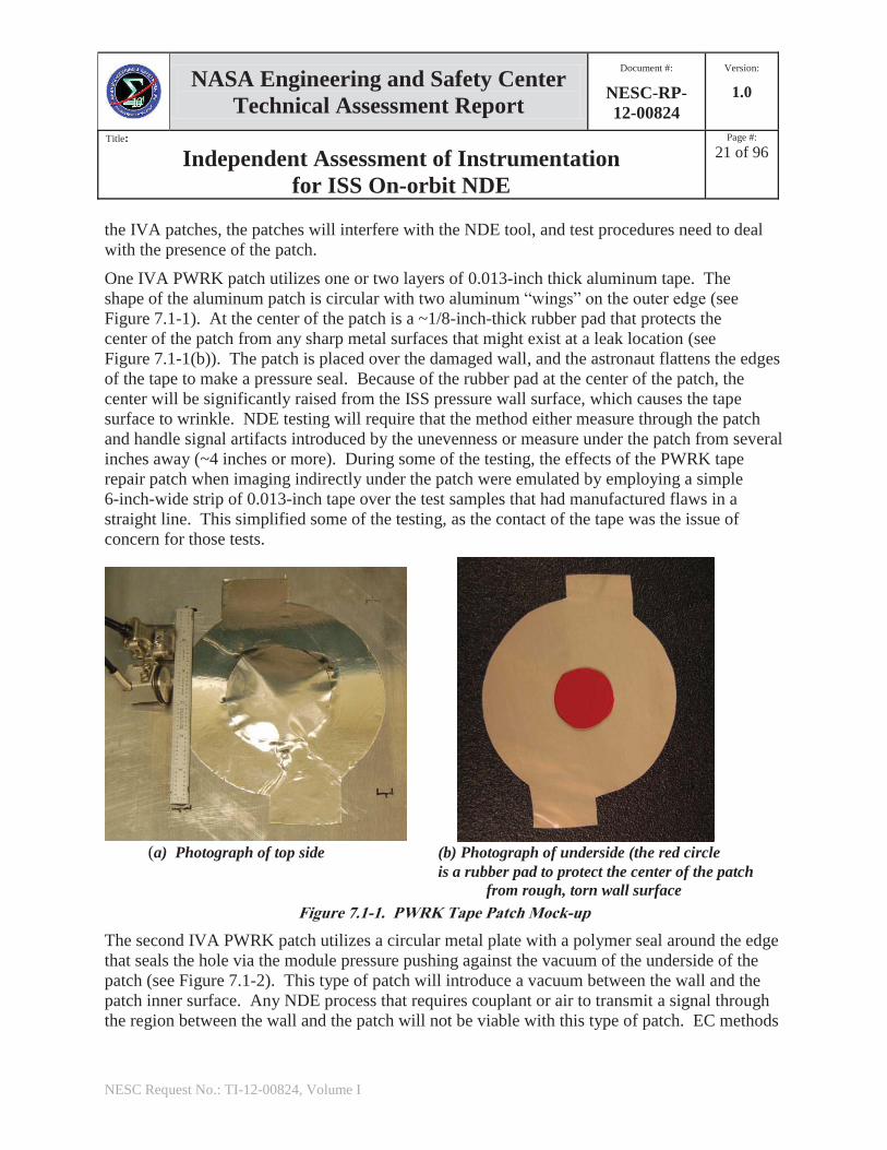
the IVA patches, the patches will interfere with the NDE tool, and test procedures need to deal with the presence of the patch.
One IVA PWRK patch utilizes one or two layers of 0.013-inch thick aluminum tape. The shape of the aluminum patch is circular with two aluminum “wings” on the outer edge (see Figure 7.1-1). At the center of the patch is a ~1/8-inch-thick rubber pad that protects the center of the patch from any sharp metal surfaces that might exist at a leak location (see Figure 7.1-1(b)). The patch is placed over the damaged wall, and the astronaut flattens the edges of the tape to make a pressure seal. Because of the rubber pad at the center of the patch, the center will be significantly raised from the ISS pressure wall surface, which causes the tape surface to wrinkle. NDE testing will require that the method either measure through the patch and handle signal artifacts introduced by the unevenness or measure under the patch from several inches away (~4 inches or more). During some of the testing, the effects of the PWRK tape repair patch when imaging indirectly under the patch were emulated by employing a simple 6-inch-wide strip of 0.013-inch tape over the test samples that had manufactured flaws in a straight line. This simplified some of the testing, as the contact of the tape was the issue of concern for those tests.
(a) Photograph of top side (b) Photograph of underside (the red circle is a rubber pad to protect the center of the patch from rough, torn wall surface
Figure 7.1-1. PWRK Tape Patch Mock-up
The second IVA PWRK patch utilizes a circular metal plate with a polymer seal around the edge that seals the hole via the module pressure pushing against the vacuum of the underside of the patch (see Figure 7.1-2). This type of patch will introduce a vacuum between the wall and the patch inner surface. Any NDE process that requires couplant or air to transmit a signal through the region between the wall and the patch will not be viable with this type of patch. EC methods
NASA Engineering and Safety Center Technical Assessment Report
Document #:
NESC-RP-12-00824
Version:
1.0
Title:
Independent Assessment of Instrumentation for ISS On-orbit NDE
Page #:
22 of 96
NESC Request No.: TI-12-00824, Volume I
will have to transmit the electromagnetic field through the patch, the center of which might be ~1/2 inch above the surface, as well as through the pressure wall to interrogate the pressure wall for defects. Ultrasonic methods will need to send ultrasonic energy along the pressure wall from outside the patch to the area of interest under the patch that will be several inches away (~4 inches or more).
Figure 7.1-2. PWRK Plate Patch
7.1.2 Test Standards and Samples The term “test standards” will be used to refer to machine-manufactured test objects. Test samples will refer to test objects that are made by less exact operations, such as hypervelocity impacts.
Standards 1A and 1B, which were rib-stiffened plates, represented a typical geometry from the Russian hardware with a small-rib wall separation (~3-inch square, 1/16-inch thin wall) (see Figure 7.1-3). This wall type is found on the Russian SM (Zvezda) and FGB (Zarya). In the case of the SM, the waffle pattern was on the inside of the module; for the FGB, the pattern was on the outside of the module. Standard 1A had flaws generated on the waffle side of the plate, while Standard 1B had the flaws place on the smooth side. To emulate cracks and pits in the FGB and SM standards, EDM notches 0.100 inch long and either 0.010 or 0.020 inch deep were manufactured. To emulate pits, partial through-the-thickness holes were drilled with a 3/64-inch-diameter drill to depths of 0.010 and 0.020 inch. These flaws were mostly located adjacent to the ribs of the waffle pattern.
NASA Engineering and Safety Center Technical Assessment Report
Document #:
NESC-RP-12-00824
Version:
1.0
Title:
Independent Assessment of Instrumentation for ISS On-orbit NDE
Page #:
23 of 96
NESC Request No.: TI-12-00824, Volume I
(a) SM wall with manufactured flaws (red dots on left side are EDM notch
locations; red dots on right side are partial through-the-wall hole locations)
(b) FGB wall with manufactured flaws (red dots on left side are EDM notch
locations; red dots on right side are partial through-the-wall hole locations
Figure 7.1-3. FGB and SM Style Rib-stiffened Walls
For the U.S. ISS modules, there are large acreage areas with 3/16-inch thick walls, with widely spaced stiffening ribs. Standard 2 was a flat aluminum 3/16-inch plate that contained a row of EDM notches two inches from one edge and a row of partial through-the-thickness holes 2 inches from another edge (see Figure 7.1-4). The EDM notches ranged from depths of 0.025 to 0.125 inch and lengths of 0.032 to 0.094 inch. The holes had diameters of 1/32 to 3/32 inch and depths of 0.025 to 0.100 inch.
NASA Engineering and Safety Center Technical Assessment Report
Document #:
NESC-RP-12-00824
Version:
1.0
Title:
Independent Assessment of Instrumentation for ISS On-orbit NDE
Page #:
24 of 96
NESC Request No.: TI-12-00824, Volume I
Figure 7.1-4. Standard 4, with the Same Manufactured Flaw Pattern as in Standard 2 (red dots on right side are EDM notch locations; red dots along top side are partial through-the-thickness hole
locations)
Standard 3 represented a multisite damaged plate that was 3/16-inch-thick aluminum plate and had partial through-the-thickness holes placed in concentric circular patterns (see Figure 7.1-5). The outer circle (4-inch diameter) consisted of 24 0.031-inch-diameter holes ranging in depth from 0.025 to 0.125 inch. Next was a ring (3-inch diameter) of 12 0.063-inch-diameter holes ranging in depth from 0.025 to 0.125 inch. Finally, there was a ring (2-inch diameter) of 12 0.094-inch-diameter holes ranging in depth from 0.025 to 0.125 inch. With this sample, one could begin to understand the effects of multisite damage on the NDE signals and images.
NASA Engineering and Safety Center Technical Assessment Report
Document #:
NESC-RP-12-00824
Version:
1.0
Title:
Independent Assessment of Instrumentation for ISS On-orbit NDE
Page #:
25 of 96
NESC Request No.: TI-12-00824, Volume I
Figure 7.1-5. Standard 3, with Partial Through-the-wall Holes Organized as Three Rings
around 1-inch, Large Flat-bottom Partial Through-hole at Plate Center
Standard 4 mimicked Standard 2, except that the aluminum plate was only 0.063 inch thick (Russian hardware thickness). In this standard, the EDM notches were either 0.100 or 0.200 inch long with depths ranging from 0.005 to 0.040 inch (see Figure 7.1-4).
Standard 5 mimicked Standard 3, except that the aluminum plate was only 0.063 inch thick (Russian hardware thickness) (see Figure 7.1-6). In this standard, the holes were in the same patterns and diameters as for Standard 3, but the depths ranged from 0.005 to 0.040 inch.
Figure 7.1-6. Standard 5, with Partial Through-the-wall Holes Organized as Three Rings
around 1-inch Large Through-hole at Plate Center
Standard 6A and 6B mimics Standard 2, except that these test standards had an 84-inch-radius curvature in the aluminum plate (see Figure 7.1-7). Plate 6A had the curvature parallel to the
NASA Engineering and Safety Center Technical Assessment Report
Document #:
NESC-RP-12-00824
Version:
1.0
Title:
Independent Assessment of Instrumentation for ISS On-orbit NDE
Page #:
26 of 96
NESC Request No.: TI-12-00824, Volume I
row of EDM notches, while Plate 6B had the curvature parallel to the row of partial through-the-thickness holes. The purpose of this standard was to demonstrate the ability of the NDE method to correctly handle the curvature of an ISS module.
Figure 7.1-7. Standard 6A, which has the Same Manufactured Flaw Pattern as Created in
Standard 2 (red dots on right side are EDM notch locations, and red dots along the topside are partial through-the-wall hole locations; Standard 6B is the same size, except that the EDM notches and partial through-the-thickness hole locations are transposed; the photo on the left side indicates
the curvature of the plate)
Standard 7A and 7B mimicked Standards 6A and 6B, except that the radius of curvature was more severe at 25 inches (see Figure 7.1-8). The purpose of these standards was to demonstrate the ability of the NDE method to correctly handle the small radii of curvature found in some parts of the ISS modules.
NASA Engineering and Safety Center Technical Assessment Report
Document #:
NESC-RP-12-00824
Version:
1.0
Title:
Independent Assessment of Instrumentation for ISS On-orbit NDE
Page #:
27 of 96
NESC Request No.: TI-12-00824, Volume I
Figure 7.1-8. Standard 7B, which has the Same Manufactured Flaw Pattern as Created in
Standard 2 (red dots on the left side are EDM notch locations, and red dots along the topside are partial through-the-wall hole locations; Standard 7A is the same size, except that the EDM notches and partial through-the-thickness hole locations are transposed; the photo on the left side indicates
the curvature of the plate)
Figure 7.1-9 is a photograph of an impact-damaged plate, numbered 186. This plate had one small penetration and a small region of severe pitting, and the surface was also deformed.
NASA Engineering and Safety Center Technical Assessment Report
Document #:
NESC-RP-12-00824
Version:
1.0
Title:
Independent Assessment of Instrumentation for ISS On-orbit NDE
Page #:
28 of 96
NESC Request No.: TI-12-00824, Volume I
Figure 7.1-9. Backside of Impact Plate 186 (this plate shows one visible penetration, a region of
deformation of the plate, and a small area of pitting)
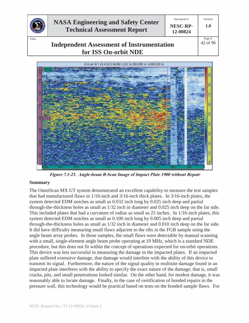
Figure 7.1-10 is a photograph of an impact damaged plate, numbered 1900. This plate had one large penetration (>1 inch) and a large region of severe pitting; further, the surface was heavily deformed. The penetration was in the form a large, long C-shaped crack.
NASA Engineering and Safety Center Technical Assessment Report
Document #:
NESC-RP-12-00824
Version:
1.0
Title:
Independent Assessment of Instrumentation for ISS On-orbit NDE
Page #:
29 of 96
NESC Request No.: TI-12-00824, Volume I
Figure 7.1-10. Backside of Impact Plate 1900, a 1/8-inch-thick Panel (this plate shows major cracking at the plate’s center; the whole center region is deformed, pushing away from the
backside; and there is extensive pitting around the center regions)
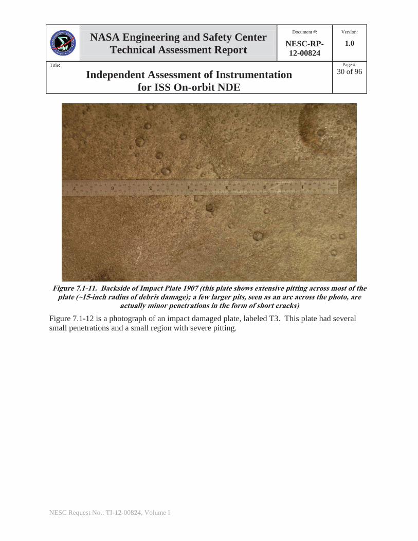
Figure 7.1-11 is a photograph of an impact-damaged plate, numbered 1907. This plate had several small penetrations and a large region of pitting. There were numerous small bumps corresponding to deep pits and the small penetrations. The small penetrations often had small short cracks emanating from them.
NASA Engineering and Safety Center Technical Assessment Report
Document #:
NESC-RP-12-00824
Version:
1.0
Title:
Independent Assessment of Instrumentation for ISS On-orbit NDE
Page #:
30 of 96
NESC Request No.: TI-12-00824, Volume I
Figure 7.1-11. Backside of Impact Plate 1907 (this plate shows extensive pitting across most of the
plate (~15-inch radius of debris damage); a few larger pits, seen as an arc across the photo, are actually minor penetrations in the form of short cracks)
Figure 7.1-12 is a photograph of an impact damaged plate, labeled T3. This plate had several small penetrations and a small region with severe pitting.
NASA Engineering and Safety Center Technical Assessment Report
Document #:
NESC-RP-12-00824
Version:
1.0
Title:
Independent Assessment of Instrumentation for ISS On-orbit NDE
Page #:
31 of 96
NESC Request No.: TI-12-00824, Volume I
Figure 7.1-12. Backside of Impact Plate T3 (his plate shows major pitting near the center of the
plate; a few larger pits are penetrations through the plate)
Figure 7.1-13 is a photograph of backside of impact plate 243. This plate represents the FGB wall configuration and was impacted with a hypervelocity projectile on the waffle side of the plate. There were several small penetrations, some of which are highlighted in red, as well as two major penetrations. This plate shows major pitting near the center of the plate. A few larger pits were penetrations through the plate. The areas in between the waffle walls showed deformation.
NASA Engineering and Safety Center Technical Assessment Report
Document #:
NESC-RP-12-00824
Version:
1.0
Title:
Independent Assessment of Instrumentation for ISS On-orbit NDE
Page #:
32 of 96
NESC Request No.: TI-12-00824, Volume I
Figure 7.1-13. Backside of Impact Plate 243, which Represents FGB Wall and was Impacted with a Hypervelocity Projectile (the impact was performed from the waffled side of the plate; because of the thin wall, there are many small penetrations, some of which are highlighted in red, as well as
two major penetrations; this plate shows major pitting near the center of the plate, and a few larger pits are penetrations through the plate; the areas in between the waffle walls show deformation)
7.1.3 Testing Configurations
7.1.3.1 Phased Array Ultrasonic Testing Phased array instruments are high-end ultrasonic testing instruments that allow significant flexibility in testing. For the concepts of operations that were envisioned in this series of tests, there will be a repair patch covering the area of concern, as discussed in Section 7.1.2. With ultrasonics, there will be a need to be able to inject ultrasonic energy into the pressure wall outside the repair area and have that energy travel in the pressure wall into the region of interest. This will be accomplished by having the array probe mounted on an “angle beam” block that will direct the energy in the direction desired (see Figure 7.1-14). Many beam angles are available from an array probe, and those many angles are denoted in the figure as the array sector beam. Each single beam from the array probe will result in the beam being refracted at the angle beam
NASA Engineering and Safety Center Technical Assessment Report
Document #:
NESC-RP-12-00824
Version:
1.0
Title:
Independent Assessment of Instrumentation for ISS On-orbit NDE
Page #:
33 of 96
NESC Request No.: TI-12-00824, Volume I
block to pressure shell interface, according to Snell’s Law. If the component under test is thin, then each beam will be reflected repeatedly against the top and bottom of the pressure wall as it transmits toward the region of interest. This concept will allow the ultrasonic energy to pass under a repair patch (denoted as a plate repair cross section in this figure) and to interrogate the region of interest. In the case of the tape repair patch, the presence of the tape and adhesive causes additional attenuation at each reflection off the aluminum-to-tape interface.
Figure 7.1-14. Phased Array-angle Beam Block Probe Geometry for
Scanning under a Patch Repair
In ultrasonics, there are several imaging formats that are common. The simplest format is called an A-scan. An A-scan represents a graph where the time or horizontal axis is the depth into a part and the vertical axis is the signal strength.
A second format is called a B-scan. This type of image represents an image where one direction denotes the time of flight of the signal into the sample (or by knowing the sample’s speed of sound, the depth into the sample that the signal travels), while the other direction represents the spatial location of the probe. In a sense, each scan location is like a separate A-scan, and all of the A-scans are being combined into a composite image. The image color or shade represents the signal strength or amplitude of the A-scans. Typically, a B-scan would show an image of the cross section of a part. In Figure 7.1-14, the B-scan is an image made from one refracted/ reflected beam path as the probe is scanned along.
A third format is called a C-scan. In that imaging format, an x-y scan is made, and at each (x, y) position, the signal amplitude is computed (usually the maximum signal at that point). For array probes, a zero-angle probe (see Figure 7.1-15) can be used to generate a C-scan by letting the probe length measure one dimension and scanning the probe in the perpendicular direction to produce a C-scan image that is as wide as the probe and as long as the scan dimension.
A fairly new scan format, called a Top-scan, is possible with ultrasonic arrays. This scan is presented in a B-scan format, but instead of utilizing a single beam path from an array sector
Array probe Angle beam block
Pressure wall
crack
One refracted/reflected beam path Array sector beam
Plate repair cross section
NASA Engineering and Safety Center Technical Assessment Report
Document #:
NESC-RP-12-00824
Version:
1.0
Title:
Independent Assessment of Instrumentation for ISS On-orbit NDE
Page #:
34 of 96
NESC Request No.: TI-12-00824, Volume I
beam (see Figure 7.1-14), a range of beam paths is used and averaged to produce a more stable image of the underlying structure. Each ultrasonic device tested was equipped to display A-scans, B-scans, and C-scans. Only one of the instruments tested supported the Top-scan feature, but it was considered a significant improvement for less skilled operators.
For areas where the repair patch does not interfere with the ultrasonics beam path, in addition to the angle beam block a zero-angle beam can be used (see Figure 7.1-15) to produce a C-scan. Using this probe configuration, a direct thickness map of a damaged outer wall would be possible. The advantage of this configuration is that wide swaths of the plate are measured at one time. This method is also applicable to scanning of bond lines. For both the B-scan and C-scan, when the probe is coupled with an accurate encoder wheel it is expected that an accurate map of the damage area will be possible.
Figure 7.1-15. Phased Array Zero-angle Beam Block Probe Geometry for
Scanning Pressure-Wall Thickness
Excellent tutorial materials for PAUT scanning are available at the Olympus knowledge Web page [ref. 6].
7.1.3.2 EC Testing EC technologies are attractive for use in metal pressure vessel structures, especially when the flaw is on the same side as the probe. They do not require a couplant and have excellent sensitivity to vertical cracks at the surface. For the case where the flaw is on the far side of the wall, the issue of radio frequency (RF) penetration is a concern. Figure 7.1-16 illustrates this point, showing an EC probe and indicating the RF field depth of penetration. RF penetration in metals can be limited. Since the penetration is inversely proportional to frequency, operating at
Array
Array sector beam One reflected beam path
Zero-angle beam block
Pressure wall
NASA Engineering and Safety Center Technical Assessment Report
Document #:
NESC-RP-12-00824
Version:
1.0
Title:
Independent Assessment of Instrumentation for ISS On-orbit NDE
Page #:
35 of 96
NESC Request No.: TI-12-00824, Volume I
low frequencies can allow some penetration through metal for detection of flaws on the far side of a part. But, as the frequency lowers, the spatial resolution also declines.
The ability to manufacture thin EC arrays on flexible substrates is one feature that is attractive for imaging purposes on the ISS. Two of the units tested for this assessment were able to support array imaging, while the third device incorporated a rapid mechanical scanning system. C-scan styled images based on array probes or rapid mechanical scanning instruments increase throughput significantly.
Figure 7.1-16. EC Probe Geometry for Scanning near Patch Repair
Tutorial materials for EC and EC array testing are available at the Olympus knowledge Web page [ref. 7].
7.1.4 Olympus Omniscan MX UT The OmniScan MX is an advanced, multi-technology flaw detector. It offers a high acquisition rate and extensive software features in a portable, modular instrument to efficiently perform both manual and automated inspections. One unique aspect of this device is that by exchanging a hardware module in the rear, this system has the ability to operate as either an ultrasonic phased array and conventional ultrasound system or, alternatively, as a conventional EC and EC array system.
The system can run on batteries, direct current (DC) power, or 115 Volts alternating current (AC) power. Setup is quick, with just a few connectors, some of which are keyed connectors. A setup configuration file can be saved for use by others. There is a memory port for a compact flash card, ports for a keyboard and computer mouse, and a video graphics array (VGA) output for displaying images on a separate terminal. Data scans can be saved to memory. There is an Ethernet connector for connection to a local area network (LAN). Personal computer (PC)-based software exists to reanalyze data after it has been taken and stored. There are several display modes that can be selected, such as phased array sector scans and conventional A-scan, B-scan, and C-scan; these can be shown in groups or individually. Encoder wheeled systems are
EC probe
Pressure wall
Crack or pit
Plate repair cross section
RF beam penetration pattern
RF field lines
NASA Engineering and Safety Center Technical Assessment Report
Document #:
NESC-RP-12-00824
Version:
1.0
Title:
Independent Assessment of Instrumentation for ISS On-orbit NDE
Page #:
36 of 96
NESC Request No.: TI-12-00824, Volume I
available to track sensor position, which will help with defect sizing. With a phased array sensor, only a single encoder wheel is required to make a two-dimensional B-scan.
The system has physical menu buttons on the left and bottom sides (see Figure 7.1-17). These buttons activate menu items on the screen. There is a keypad and a click wheel on the right for setting values. The keypad on the right also can be used to activate specific operation controls. The menu buttons often activate additional submenus, which may activate another layer of submenus.
Figure 7.1-17. Olympus Omniscan MX UT Model
Figure 7.1-18 shows the results of scanning the simplest standard used in this testing, Standard 2. Figure 7.1-18(a) shows a linear B-scan across a row of notches, scanned from 4 inches away from the notches, while 7.1-18(b) shows a similarly configured linear B-scan across a row of partial through-the-thickness holes. The black circles highlight the location of the EDM notches and the partial through-the-thickness holes in the images. In a B-scan image, the reverberation of the signal causes the short horizontal lines that appear in the echo from a flaw. Both of these scans were performed using an angle beam phased array setup. In addition, the test standard also had a layer of 0.013-inch aluminum tape applied to the scanned area to emulate the effect of the PWRK tape patch. For that scanning configuration, the tape caused between 6 to 10 dB of signal loss compared with the same scans without the tape present, where the reflections of the ultrasonic beam between the top surface and the tape were lossy. Scanning with a PWRK plate patch or scanning without a patch had more signal-to-noise and sensitivity/resolution. As can be seen, all of the holes and notches were detected with this instrument. The smallest hole was 1/32 inch in diameter and 0.025 inch deep. The smallest notch was 0.032 inch long and 0.025 inch deep. This compares favorably with detection requirements specified under
NASA Engineering and Safety Center Technical Assessment Report
Document #:
NESC-RP-12-00824
Version:
1.0
Title:
Independent Assessment of Instrumentation for ISS On-orbit NDE
Page #:
37 of 96
NESC Request No.: TI-12-00824, Volume I
NASA-STD-5009 for conventional scanning methods [ref. 4]. The signal form caused by the flaw in the figure represents the local reverberation pattern of the ultrasonic echo. That pattern will shift around slightly for different beam angles, but the overall echo location should be constant.
(a) Row of notches detected with layer of tape covering the area to emulate effects of PWRK
tape patch
(b) Row of partial through-the-thickness holes detected with layer of tape covering the area to
emulate effects of PWRK tape patch Figure 7.1-18. Angle-beam Scans of Standard 2 (B-scan image representations show the distance the ultrasonic beam travels (Y-axis, with the top at y = 0 and the bottom at y ~ 4 inches) and the
physical horizontal probe position (X-axis, 0 to 11 inches); the variations in the intensity represent the beam’s echo strength)
Figure 7.1-19 shows a series of angle beam B-scans images made on Standard 3. This panel represents multisite damage in the form of partial through-the-thickness holes (emulating pits in the material). The holes were drilled in a series of concentric rings of holes, with the largest diameter holes in the inner ring and the smallest diameter holes in the outer ring. Figure 7.1-19(a) shows that all of the holes near the transducer are detected. As the signal travels further along the plate, detection degrades in part due to interference from holes in the beam’s path as well as from signal diffraction and attenuation. The black circle indicates a location where the location of a hole is uncertain. Figure 7.1-19(b) shows the effects of placing a PWRK tape patch on the sample. One of the small holes (0.031-inch diameter and 0.025-inch depth) was lost in the noise indicated by the black circle, while all of the remaining holes were still detected. Figure 7.1-19(c) shows the detection of all of the holes in the full composite image, except for two small holes (one with a 0.031-inch diameter and 0.025-inch depth, and one with a 0.031-inch diameter and 0.050-inch depth), and one hole with a 0.063-inch diameter and 0.025-inch depth. This image shows that utilizing multiple scans can help capture a full image of the area under a patch.
NASA Engineering and Safety Center Technical Assessment Report
Document #:
NESC-RP-12-00824
Version:
1.0
Title:
Independent Assessment of Instrumentation for ISS On-orbit NDE
Page #:
38 of 96
NESC Request No.: TI-12-00824, Volume I
(a) Image of partial through-the-thickness holes detected without a PWRK patch present
(b) Image of partial through-the-thickness holes detected with PWRK tape patch
(c) Composite image using image from panel (a) and complementary image
made from opposite side of tape patch
Figure 7.1-19. Angle-beam Scans of Standard 3
Figure 7.1-20 shows a composite image of five 0-degree beam C-scans of Standard 3. This image shows that this system can detect pits without the presence of a repair patch. This would be the case for imaging hidden damage that extends beyond the patch repair area, which is common for some types of MMOD damage. By setting certain imaging parameters, the C-scan can be set up so that the depth of the pits would be resolvable.
NASA Engineering and Safety Center Technical Assessment Report
Document #:
NESC-RP-12-00824
Version:
1.0
Title:
Independent Assessment of Instrumentation for ISS On-orbit NDE
Page #:
39 of 96
NESC Request No.: TI-12-00824, Volume I
Figure 7.1-20. Composite Image from Five Zero Beam C-scans of Standard 3
Figure 7.1-21 shows an angle beam B-scan image of Sample 186, which shows an impact region that includes one penetration, deformation, and pitting in the region of impact. The yellow and red signals represent the deepest damage regions, including the through-the-wall penetration. This type of scan does not allow specific differentiation of the damage type, whether it is a penetration or a pit, but it does allow location of damage. The red circle highlights the penetration, and the black circles highlight regions of severe pitting.
NASA Engineering and Safety Center Technical Assessment Report
Document #:
NESC-RP-12-00824
Version:
1.0
Title:
Independent Assessment of Instrumentation for ISS On-orbit NDE
Page #:
40 of 96
NESC Request No.: TI-12-00824, Volume I
Figure 7.1-21. Angle Beam B-scan Image of Impact Plate 186 without Repair
Figure 7.1-22 shows an angle beam B-scan image of impact plate 1907. This plate had an extensive damage region with a few deep pits, some of which penetrated through the sample and are seen as the dark blue, yellow, and red colors in the figure, circled in red. A smaller probe was useful for scanning this plate because of the uneven surface caused by some of the dents. The deepest dents are evident in the image in the proper position.
NASA Engineering and Safety Center Technical Assessment Report
Document #:
NESC-RP-12-00824
Version:
1.0
Title:
Independent Assessment of Instrumentation for ISS On-orbit NDE
Page #:
41 of 96
NESC Request No.: TI-12-00824, Volume I
Figure 7.1-22. Angle-beam B-Scan Image of Impact Plate 1907 without Repair
Figure 7.1-23 is an angle beam B-scan image of impact plate 1900. The top of the image represents the position y = 0; the bottom of the image represents a distance of ~4 inches from the probe. This plate was 1/8 inch thick, the same as the Russian and U.S. hardware wall thicknesses. It suffered broad area damage in the form of severe pitting, as well as a large crack at the center of the plate. For this configuration, the pitting damage scattered the signal so strongly that the signal was quickly attenuated before it could travel the necessary distance to the center of the sample where a critical, large crack was located. In this figure, the red, yellow, and green signals represent the severe pitting of the damage. As the distance reaches about 2.5 inches from the probe, the beam’s signal is falling into the noise, and damage is no longer being imaged clearly. If the signal had not been attenuated, the critical crack would have been seen at the bottom of the scan. The artifacts on the left side of the image are caused by the operator losing contact between the probe and the sample. While a 0-degree scan can also image the severe pitting, it would be unable to image the center region under the patch because of the surface deformation. It could only scan areas outside the patch area.
NASA Engineering and Safety Center Technical Assessment Report
Document #:
NESC-RP-12-00824
Version:
1.0
Title:
Independent Assessment of Instrumentation for ISS On-orbit NDE
Page #:
42 of 96
NESC Request No.: TI-12-00824, Volume I
Figure 7.1-23. Angle-beam B-Scan Image of Impact Plate 1900 without Repair
Summary The OmniScan MX UT system demonstrated an excellent capability to measure the test samples that had manufactured flaws in 1/16-inch and 3/16-inch thick plates. In 3/16-inch plates, the system detected EDM notches as small as 0.032 inch long by 0.025 inch deep and partial through-the-thickness holes as small as 1/32 inch in diameter and 0.025 inch deep on the far side. This included plates that had a curvature of radius as small as 25 inches. In 1/16-inch plates, this system detected EDM notches as small as 0.100 inch long by 0.005 inch deep and partial through-the-thickness holes as small as 1/32 inch in diameter and 0.010 inch deep on the far side. It did have difficulty measuring small flaws adjacent to the ribs in the FGB sample using the angle beam array probes. In those samples, the small flaws were detectable by manual scanning with a small, single-element angle beam probe operating at 10 MHz, which is a standard NDE procedure, but this does not fit within the concept of operations expected for on-orbit operations. This device was less successful in measuring the damage in the impacted plates. If an impacted plate suffered extensive damage, that damage would interfere with the ability of this device to transmit its signal. Furthermore, the nature of the signal quality in multisite damage found in an impacted plate interferes with the ability to specify the exact nature of the damage; that is, small cracks, pits, and small penetrations looked similar. On the other hand, for modest damage, it was reasonably able to locate damage. Finally, in the case of certification of bonded repairs in the pressure wall, this technology would be practical based on tests on the bonded sample flaws. For
NASA Engineering and Safety Center Technical Assessment Report
Document #:
NESC-RP-12-00824
Version:
1.0
Title:
Independent Assessment of Instrumentation for ISS On-orbit NDE
Page #:
43 of 96
NESC Request No.: TI-12-00824, Volume I
the Omniscan MX UT testing, these results were not saved for this report but were equivalent to the results for the Sonatest Veo (Appendix E). The available results for the Olympus Omniscan MX UT system are shown in Appendix D.
7.1.5 Sonatest Veo The Sonatest Veo Phased Array ultrasonic flaw detector is an advanced flaw detector with an easy-to-view visual display (see Figure 7.1-24). The Veo’s simple controls are another notable feature. The simple play, pause, record, and stop buttons are reminiscent of a video control remote or digital video disc controller, which is familiar to most people. The menu setup is easy to follow, with only one level of menus. The system has both a keypad and a click wheel on the left side for setting values. The display is set up as a four-panel system with the ability to quickly step through the individual display panels and to expand or condense the panels. The system can run on batteries or 115 Volts AC power.
Setup is quick with keyed connectors. A setup configuration file can be saved for use by others. There are universal serial bus (USB) ports for memory sticks, keyboard, computer mouse, and a VGA output for displaying images on a separate terminal. Data scans can be saved to memory. There is an Ethernet connector for connection to a LAN. PC software exists to reanalyze data after it has been taken and stored. There are dozens of display modes. One signal processing display that is unique and beneficial is the Top-scan, which the Omniscan MX does not provide. Top-scan is similar to a B-scan in presentation format, but it has the advantage of averaging many array sector angles together to give a much “smoother” view of flaws, while the B-scan by definition only presents one sector angle from the array probe. While someone skilled in the art can use either display type to quantify a flaw equally well, the Top-scan may be easier for less skilled individuals to see and comprehend images. Plus, more importantly, when saving the data from a Top-scan process, all the angles of data are saved and can be used for further processing later. If one scan angle is not clear enough for a given purpose, another one might be far superior. While this represents a great deal more data, it does allow someone on the ground to post-process the data and make adjustments to use angles that might provide better views of a flaw than what was originally estimated. For on-orbit operations with subsequent ground-based evaluation, this is an advantage over the Omniscan MX UT instrument and is a significant finding. The system comes with an encoder wheel to be used with the array probe, which will provide one of the scan dimensions seen in a B-scan or a Top-scan.
NASA Engineering and Safety Center Technical Assessment Report
Document #:
NESC-RP-12-00824
Version:
1.0
Title:
Independent Assessment of Instrumentation for ISS On-orbit NDE
Page #:
44 of 96
NESC Request No.: TI-12-00824, Volume I
Figure 7.1-24. Front Panel of Sonatest Veo System
Figure 7.1-25 shows several scan views of Standard 2 in a Top-scan mode. In each of these images, the probe is just beyond the edge of the tape at the top of the images. The top of the figures represents y ~ 1 inch, and the bottom is about 4.5 inches from the probe. Panel (a) represents a Top-scan of the row of partial through-the-thickness holes in the plate with 0.013-inch aluminum tape on the surface (marked with circles). The smallest hole (0.032 inch in diameter and 0.025 inch deep), marked by a red circle, is barely detectable (near the noise floor). As was mentioned in the Omniscan MX testing, the tape added about 6 to 10 dB of signal loss. Panel (b) represents the same region shown as a composite image, made with the plate patch. The increased signal gain that was lost in the tape patch is evident. All of the holes were detected in that scan and are marked with circles. Panel (c) represents a scan of the row of EDM notches in the plate with 0.013-inch aluminum tape on the surface. The EDM notches are marked with circles. The smallest hole (0.032 inch in diameter and 0.025 inch deep) is easily detected. Panel (d) represents the same region shown as a composite image, but with the plate patch. All of the detected notches in the scan are marked with black circles. The one notch not detected is marked with a red circle and is the smallest notch (0.032 inch in length and 0.025 inch deep). The variability in these images reflects the operator’s skill and shows that the flaw detection limit is at the 0.032-inch length and 0.025-inch depth. In all these scans, the effects of the Top-scan imaging make for a more easily viewed image.
NASA Engineering and Safety Center Technical Assessment Report
Document #:
NESC-RP-12-00824
Version:
1.0
Title:
Independent Assessment of Instrumentation for ISS On-orbit NDE
Page #:
45 of 96
NESC Request No.: TI-12-00824, Volume I
(a) Holes with tape repair
(b) Holes with repair plate
(c) Notches with tape repair
NASA Engineering and Safety Center Technical Assessment Report
Document #:
NESC-RP-12-00824
Version:
1.0
Title:
Independent Assessment of Instrumentation for ISS On-orbit NDE
Page #:
46 of 96
NESC Request No.: TI-12-00824, Volume I
d) Notches with repair plate
Figure 7.1-25. Top-scan Images of Standard 2
Figure 7.1-26 shows a series of angle beam Top-scan images made on Standard 3. This panel represents multisite damage in the form of partial through-the-thickness holes (pits). The holes were drilled in a series of concentric rings of holes, with the largest diameter holes in the inner ring and the smallest diameter holes in the outer ring. Figure 7.1-26(a) shows that all of the holes near the transducer were detected. As the signal traveled further along the plate, detection degraded, in part due to interference from holes in the beam’s path, and from signal diffraction and attenuation. Figure 7.1-26(b) shows the effects of placing 0.013-inch aluminum tape on the sample. One of the shallower holes (0.063 inch in diameter and 0.025 inch deep) was lost in the noise, while the remaining holes were detected. Figure 7.1-26(c) shows the detection of all of the holes in the full composite image. This image demonstrates that by utilizing multiple scans one could capture a full image of the area under a patch. Figure 7.1-26(d) shows a composite image of three 0-degree beam scans of Standard 3. This image shows that this system can detect pits without the presence of a repair patch. This would be the case for imaging hidden damage that extends beyond the patch repair area, which is common for some types of MMOD damage. By setting certain imaging parameters, this C-scan can be set so that the depth of the pits would be resolvable.
NASA Engineering and Safety Center Technical Assessment Report
Document #:
NESC-RP-12-00824
Version:
1.0
Title:
Independent Assessment of Instrumentation for ISS On-orbit NDE
Page #:
47 of 96
NESC Request No.: TI-12-00824, Volume I
(a) Angle beam Top-scan, scanning from right to left without any repair
on Standard 3
(b) Same view as panel (a), except for the addition of the PWRK tape repair patch
(c) Composite view, with one Top-scan operated from bottom to top and the other
in the reverse orientation
NASA Engineering and Safety Center Technical Assessment Report
Document #:
NESC-RP-12-00824
Version:
1.0
Title:
Independent Assessment of Instrumentation for ISS On-orbit NDE
Page #:
48 of 96
NESC Request No.: TI-12-00824, Volume I
(d) A Composite view of 0-degree C-scan with ultrasonic energy traveling straight
down into the sample and back out Figure 7.1-26. Views of Standard 3
Figure 7.1-27 illustrates that ability of these arrays to operate on curved surfaces. When water is used as a couplant, the issue becomes whether the water layer can stay in contact with a curved surface and the probe as scanning is conducted. The surface tension of water causes water to stick to both surfaces. Another question is whether the curvature causes image degradation. In Figure 7.1-27(a), the image indicates the ability to detect all of the partial through-the-thickness holes in the sample with the long axis of the probe in contact with the smallest curvature of the ISS pressure wall. This image was made on the 25-inch-radius curvature surface with a PWRK plate repair. Figure 7.1-27(b) shows the ability to image EDM notches with a WPRK tape repair in place. Again, all of the holes were visible; hence, the system appears to be able to handle the 25-inch curvature with adequate clarity.
(a) Images from Standard 7A holes with a PWRK plate repair
NASA Engineering and Safety Center Technical Assessment Report
Document #:
NESC-RP-12-00824
Version:
1.0
Title:
Independent Assessment of Instrumentation for ISS On-orbit NDE
Page #:
49 of 96
NESC Request No.: TI-12-00824, Volume I
(b) Images from Standard 7B EDM notches with a tape repair
Figure 7.1-27. Top-scan Images from a Curved Sample
Figure 7.1-28 shows two image views of impact plate 186, which had a central region of damage, deformation, pitting, and one penetration. Panel (a) was scanned in a bottom to top direction, while panel (b) was scanned from the opposite direction. One of the images was flipped so that the orientation of the damage is the same in both images. The circle highlights the region of the penetration. The effect of the intervening damage regions modifies an image and is a strong argument for making multiple images from different directions to attain the most quantitative data.
(a) Scanning from the direction bottom
toward the top (b) Scanning from the direction top toward
the bottom Figure 7.1-28. Angle Beam Top-scan Images of Impact Plate 186
NASA Engineering and Safety Center Technical Assessment Report
Document #:
NESC-RP-12-00824
Version:
1.0
Title:
Independent Assessment of Instrumentation for ISS On-orbit NDE
Page #:
50 of 96
NESC Request No.: TI-12-00824, Volume I
Figure 7.1-29 shows an attempt to image damage in impact plate 1900 with a PWRK repair plate in place. The image shows the limitation of the angle beam scans when trying to travel long paths with badly damaged surfaces. In this image, the probe is at the bottom of the image with y ~ 1 inch at the bottom and y ~ 4.5 inch at the top of the image. As a result of the strong scattering from the damage, the bottom of the image indicates significant pitting and damage, shown as the black and blue regions at the bottom; however, the ultrasonic beam has been strongly attenuated by the scattering, so it has failed to penetrate all the way to the center and top area, which contains a long critical crack-like structure. Hence, there is no reflected signal making it back to the transducer. The yellow signals at the top of the image represent weak signals.
Figure 7.1-29. Impact Plate 1900 with Plate Patch
Figure 7.1-30 shows the Top-scan image results of impact plate T3, which has a local region of deep pits and a single penetration. Rows and groups of deep pits were detected. The deep pits are imaged as blue regions. The penetration lies in the circled region.
NASA Engineering and Safety Center Technical Assessment Report
Document #:
NESC-RP-12-00824
Version:
1.0
Title:
Independent Assessment of Instrumentation for ISS On-orbit NDE
Page #:
51 of 96
NESC Request No.: TI-12-00824, Volume I
Figure 7.1-30. Top-scan Image of Impact Plate T3 (image was scanned from left to right)
Figure 7.1-31 shows one of the most difficult impact samples to scan with ultrasonics. This panel is an emulation of the FGB skin. The figure indicates several regions of damage, including two large penetrations. The major difficulty with this sample was the presence of the rib structures, which caused large reflections. If a scan was performed perpendicular to these ribs, the reflections were so large that they disguised any damaged regions while highlighting the ribs. The ability to image the rib patterns is helpful for understanding the orientation of the damage relative to the structure, but at the cost of detecting damage that is close to the ribs. By scanning at 45 degrees to the ribs, most of the energy is lost in the reflections, and the reflections from the ribs miss the probe; thus, the important signals (i.e., those from the damaged areas) are greatly reduced. The array probes do not have enough energy to penetrate to and reflect off the damaged regions. By using a single-element angle beam transducer, a much larger pulser signal is allowed, which allows the signal to penetrate farther, but the flaw indications in the image still are not strong. In Figure 7.1-31, indications that correspond to the damaged areas are highlighted. The red circles indicate large penetrations. The blue ovals are regions where extensive pitting and small penetrations exist.
NASA Engineering and Safety Center Technical Assessment Report
Document #:
NESC-RP-12-00824
Version:
1.0
Title:
Independent Assessment of Instrumentation for ISS On-orbit NDE
Page #:
52 of 96
NESC Request No.: TI-12-00824, Volume I
Figure 7.1-31. Impact Plate 243 (FGB Impacted Plate) (a single-element angle beam scan (B-scan) was made by scanning at 45 degrees to the rib structure; the damaged areas are identified with red
circles (holes) and blue ovals (regions of pitting and small penetrations))
Summary The Sonatest Veo system demonstrated an excellent capability to measure the test standards that had manufactured flaws in 1/16-inch and 3/16-inch thick plates. In 3/16-inch plates, the system detected EDM notches as small as 0.032 inch long by 0.025 inch deep and partial through-the-thickness holes as small as 1/32 inch in diameter and 0.025 inch deep on the far side. This included plates that had a curvature of radius as small as 25 inches. In 1/16-inch plates, this system detected EDM notches as small as 0.100 inch long by 0.005 inch deep and partial
NASA Engineering and Safety Center Technical Assessment Report
Document #:
NESC-RP-12-00824
Version:
1.0
Title:
Independent Assessment of Instrumentation for ISS On-orbit NDE
Page #:
53 of 96
NESC Request No.: TI-12-00824, Volume I
through-the-thickness holes as small as 1/32 inch in diameter and 0.010 inch deep on the far side. The system did have difficulty measuring small flaws adjacent to the rib in FGB samples using the angle beam array probes. This device was less successful in measuring the damage in the impacted plates. If an impacted plate suffered extensive damage, that damage interfered with the device’s ability to transmit its signal. Furthermore, the signal quality for multisite damage that occurs on an impacted plate made determination of the specific nature of the damage difficult (i.e., small cracks, pits, and small penetrations looked similar). While the system was not specific in identifying the damage type, in the case of modest damage it was able to locate the position of damage. In the case of certification of bonded repairs in the pressure wall, this technology was practical based on testing on the bonded sample flaws. Those results are given in Appendix E, in addition to other scan and evaluation information on the Sonatest Veo system.
Finally, the Top-scan imaging modality was helpful for highlighting flaws and should prove beneficial to astronauts as a tool for visualizing whether a scan is being performed correctly; it should be helpful for post-processing as more scan data are saved.
7.1.6 GE Phasor XS The GE Phasor XS is an ultrasonic phased array flaw detector (see Figure 7.1-32). The Phasor has a series of buttons on the left and bottom side of the device face. There is a click wheel for dialing in values on the left side. The screen is smaller than the displays for the Veo and the Omniscan. The menu operation is fairly straightforward. The system can run on batteries or 115 Volt AC power.
Setup and hook up of the connectors is quick. The array connector can be quickly snapped in place, as opposed to using threaded screws to anchor the plug. As with the other systems, a setup configuration file can be saved for use by others. There is a VGA output for displaying images on a separate terminal. Data scans can be saved to memory. There are fewer display modes, but the system does support a Top-scan capability similar to that of the Veo system. An encoder wheel can be purchased to support B-scan and Top-scan capabilities.
NASA Engineering and Safety Center Technical Assessment Report
Document #:
NESC-RP-12-00824
Version:
1.0
Title:
Independent Assessment of Instrumentation for ISS On-orbit NDE
Page #:
54 of 96
NESC Request No.: TI-12-00824, Volume I
Figure 7.1-32. GE Phasor XS System
One issue that was problematic for this testing was the limitation placed by the system on the range of the data that could be displayed. The system would only allow the image to display out to five plate reverberations when using an angle beam transducer configuration. This meant that the image display would cut off at less than an inch distance for a 3/16-inch thick plate (imaging was required out to a 4- to 6-inch distance to image under a plate patch). By declaring the plate to be much thicker (i.e., 0.5 to 1 inch in thickness), the system could be tricked into displaying a longer distance, but the imaged flaws were badly distorted.
Figure 7.1-33 shows a B-scan image result from scanning Standard 3, the sample with multiple partial through-the-thickness holes placed in concentric rings. This image shows the distortion in the image that resulted from declaring the sample to be 1inch thick instead of its actual thickness of 3/16 inch. While the scan shows several inches of the sample, it is a sufficient distance to fully image under a PWRK patch. The distortions also smear out the edges of the holes, making sizing more difficult. When the image was resized to make the indications circular, the holes appeared closer together than they actually were.
NASA Engineering and Safety Center Technical Assessment Report
Document #:
NESC-RP-12-00824
Version:
1.0
Title:
Independent Assessment of Instrumentation for ISS On-orbit NDE
Page #:
55 of 96
NESC Request No.: TI-12-00824, Volume I
Figure 7.1-33. A B-scan Image of Standard 3 showing the Results of Imaging the Multisite Partial
Through-the-thickness Holes
While the system was lacking in its ability to perform the type of angle beam scan desired, it was quite capable of performing 0-angle scans. Figure 7.1-34 shows a 0-angle scan of Standard 3 without any repair patch. In this type of imaging, the detectability depends strongly on the phased array focal laws that are used for imaging and for ISS operations; ground personnel would provide these for the ISS crew. This array focal law enhances the ability to cleanly detect major flaws. The large diameter holes (0.094 inch) are easily detected. In the next ring, some of the 0.063-inch diameter holes are detectable. Those detected flaws correspond to 0.100- and 0.125-inch deep holes on the backside. None of the 0.031-inch holes can be seen in this image.
NASA Engineering and Safety Center Technical Assessment Report
Document #:
NESC-RP-12-00824
Version:
1.0
Title:
Independent Assessment of Instrumentation for ISS On-orbit NDE
Page #:
56 of 96
NESC Request No.: TI-12-00824, Volume I
Figure 7.1-34. A 0-angle C-scan Image of Standard 5 showing the Results of Imaging the Multisite Partial Through-the-thickness Holes without a Repair Patch to Block the Probe's Access to Flaws
Figure 7.1-35 is a B-scan image of impact test plate 1907, which had several deep pits on its backside. In this slice of the plate, two indications of deep pits are seen at the center and on the right side of the scan. The echoes occur slightly above the strong back wall, indicating a measure of their depth (see white circles). Shallow pitting on the backside of the panel was too small to detect in this image.
NASA Engineering and Safety Center Technical Assessment Report
Document #:
NESC-RP-12-00824
Version:
1.0
Title:
Independent Assessment of Instrumentation for ISS On-orbit NDE
Page #:
57 of 96
NESC Request No.: TI-12-00824, Volume I
Figure 7.1-35. A B-scan Image of Impact Test Plate 1907 showing the Results of Imaging the Pits
Through-the-Thickness of the Plate without a Repair Patch
Summary Strictly speaking, with the software limitations that were encountered with the GE Phasor XS, it would be difficult for this device to adequately measure any of the manufactured test plates that were generated with EDM notches and partial through-the-wall holes, as well as the impact test plates, in the manner required. Although the system could measure thicknesses of samples, it would not be able to work in the regions under the PWRK patches, as required. This technology would be practical for the bonded sample flaws. No bond-line tests were recorded with this device. The results for the GE Phasor XS system are shown in Appendix F.
7.1.7 Olympus Omniscan MX EC This is the same unit that is displayed in Figure 7.1-17, except that this one has an EC module attached to the back. The operation of this unit was similar to that of the ultrasonic version. The graphical user interface (GUI) has a similar feel to the ultrasonic unit, except that the displays and operation menus are for an EC device. Figure 7.1-36 shows an example of the display. The best results from this device were obtained with a low-frequency array sensor (5 kHz), which was able to detect signals through nearly 1/8 inch of aluminum. The following tests with this instrument were made with the 5-kHz array probe. A C-scan of a multi-notch sample is used to calibrate the instrument for crack depth and liftoff effects. The following C-scans show a top view of the average through-the-thickness EC results.
Figure 7.1-36(a) shows an EC C-scan image of hidden partial through-the-thickness holes in Standard 4 without any PWRK patches. All of the flaws are visible in that part of the scan: hole diameters from 1/32 to 3/32 inch and hole depths from 0.010 to 0.040 inch. Figure 7.1-36(b) shows what happened with a 0.013-inch tape layer over the holes. Figure 7.1-36(b) appears to
NASA Engineering and Safety Center Technical Assessment Report
Document #:
NESC-RP-12-00824
Version:
1.0
Title:
Independent Assessment of Instrumentation for ISS On-orbit NDE
Page #:
58 of 96
NESC Request No.: TI-12-00824, Volume I
have shifted about 2 inches to the left from image (a). All of the holes are visible; the two smallest holes, with 1/32-inch diameter and 0.020- and 0.030-inch depths are faint.
(a) Detected notches on Standard 4 without any patches
(b) Effect of application of 0.013-inch aluminum tape on the test plate
Figure 7.1-36. EC C-scan Images of Partial Through-the-thickness Holes in Standard 4
Figure 7.1-37 shows an EC C-scan image of the EDM notches in Standard 4 without any PWRK patches. The slots at depths 0.005 inch are at the noise floor of the scan. All of the notches are identified with black circles. In this standard, the notches are oriented horizontally, so one would expect that the images would be longer in the x-direction, but this type of probe caused the notches to appear longer in the y-direction. It does not appear that the lengths of the notches were discerned well with this type of probe.
NASA Engineering and Safety Center Technical Assessment Report
Document #:
NESC-RP-12-00824
Version:
1.0
Title:
Independent Assessment of Instrumentation for ISS On-orbit NDE
Page #:
59 of 96
NESC Request No.: TI-12-00824, Volume I
Figure 7.1-37. EC C-scan Image of EDM Notches in Standard 4, showing the Detected Notches on
Standard 4 without any Patches
Figure 7.1-38 is an EC C-scan image of Standard 3, which is a thicker panel (Standard 4 is 0.1875 inch thick). The deep flaws are visible and are identified with black circles. The center hole, which is 1 inch in diameter, only has 0.0875 inch of metal remaining (0.100-inch deep hole). The deepest holes (0.125 inch) leave only 0.0625 inch of metal remaining. In the first ring of holes (with diameters of 0.094 inch), there are three holes with a depth of 0.0625 inch and three holes with a depth of 0.0875 inch; these are seen in the correct orientation in the figure. In the next ring, with 0.063-inch-diameter holes, two holes have a depth of 0.125 inch and two have a depth of 0.100 inch; these are seen in the correct locations in the second ring. For the smallest holes (the outer ring, 0.063-inch-diameter holes) only two of the five holes with a depth of 0.125 inch are seen as faint indications. The other three holes are outside the scan dimensions. The 0.100-inch-deep holes are not seen at the 0.063-inch-diameter hole size.
Figure 7.1-38. EC C-scan Image of Partial Through-the-thickness Holes in Standard 3,
showing the Detected Deeper Partial Through-the-thickness Holes on a Thick Test Plate (3/16-inch) without Patches
Summary This lower frequency 5-kHz probe was obtained near the end of this assessment, and the NESC team did not have adequate time to pursue testing with this sensor, as would have been preferred. The earlier (100-kHz) probe, which this system had, was too high a frequency to work on even thin metal samples, which initially yielded null results on all of the test samples from this device. By using this lower frequency probe, the Omniscan MX EC system should be able to see the
NASA Engineering and Safety Center Technical Assessment Report
Document #:
NESC-RP-12-00824
Version:
1.0
Title:
Independent Assessment of Instrumentation for ISS On-orbit NDE
Page #:
60 of 96
NESC Request No.: TI-12-00824, Volume I
deepest damage to some of the impact plates. Thus, test plates Standards 2, 3, 6A, 6B, 7A, and 7B can be scanned and the deepest pits would be detectable, but most of the shallower defects from those test panels were not deep enough for the 5-kHz probe to detect. Further, the results would be affected by the surface flatness. Bumps caused by deep pits would also have an effect on the image, which makes it unlikely that the system could give an unambiguous interpretation of the local wall thicknesses of the impacted plates. Thus, this type of system would have less success when applied to an impacted plate because if the pits were deep enough to detect it is probable that there would be surface deformation.
It should be noted that this EC array technology did not have good resolution of flaws when scanning near the ribs of a waffle structure. The array probes used in this assessment have large elements compared with the more point-like probes used in conventional EC systems. Finally, this technology would not be practical for the bonded sample flaws. The results for the Olympus Omniscan MX EC system are given in Appendix G.
7.1.8 UniWest 454A ECS3 The core of the UniWest System is the 454A EC system. As can be seen in Figure 7.1-39, the system was coupled to a mechanical scanner/encoder, which also houses a single small probe that spins around an approximately 1-inch wheel (the blue device at the lower left of the image). The 1-inch wheel can be partially seen at the far left bottom of the probe. The outputs of the probe and the 454A unit (which is at the upper left) are fed into a computer to display the data (shown at the top right). While the device has extra hardware to deal with, it is well constructed and not overly complicated to operate once set up.
The US-454A is a portable, hand-held battery-operated multi-frequency EC instrument that can be connected to a laptop, PC, and motion controllers for use in semi- or fully automatic data collection applications. Two encoder inputs enable position stamping of data. Ethernet and USB capabilities allow instrument control along with time- and position-stamped data transfer to the client computer. The 454A system is a widely used EC model that is robust. For this testing, the ECS3 scanner used a 20-KHz probe that was operated in the 12 KHz regime.
NASA Engineering and Safety Center Technical Assessment Report
Document #:
NESC-RP-12-00824
Version:
1.0
Title:
Independent Assessment of Instrumentation for ISS On-orbit NDE
Page #:
61 of 96
NESC Request No.: TI-12-00824, Volume I
Figure 7.1-39. UniWest 454A ECS3 System with Laptop Computer, which Records Data and
Displays Images
Figure 7.1-40 shows that hidden EDM notches were detected on the far side of Standard 1B. The resolution is sufficient to detect the orientation of the flaws. The rib pattern is easily seen in the top half of the image. The top half of the image is the conductivity image, while the bottom half of the image is the probe liftoff image. In these scans, the liftoff images should be uniform. In panel (a), white circles highlight the detectable flaws. The flaws that are 0.010 inch deep and those in the corners of the rib patterns are of questionable detectability, while the 0.01-inch-deep notches along the ribs are detectable (on the right half of the image). All of the 0.02-inch-deep notches (on the left side) were easily resolved. Panel (b) is an image of the same region as in panel (a), but with 0.013-inch tape applied to the surface. While the grid pattern might be vaguely discernible, none of the flaws can be resolved with any certainty.
NASA Engineering and Safety Center Technical Assessment Report
Document #:
NESC-RP-12-00824
Version:
1.0
Title:
Independent Assessment of Instrumentation for ISS On-orbit NDE
Page #:
62 of 96
NESC Request No.: TI-12-00824, Volume I
(a) Detected notches (indicated with white circles) on Standard 1b without any patches
(b) Effect of application of 0.013-inch aluminum tape on the test plate
Figure 7.1-40. EC C-scan Images of EDM Notches in Standard 1B, the FGB Patterned Test Plate
Figure 7.1-41 shows the ability to detect hidden partial through-the-thickness holes on the far side of Standard 1 (upper half of the image). The resolution is sufficient to determine that these are circular flaws. The rib pattern is easily seen. In panel (a), flaws that are either 0.010 or 0.02 inch deep are detectable and are outlined with white circles. Panel (b) is an image of the same region as in panel (a), but with 0.013-inch tape applied to the surface. Again, the grid pattern might be vaguely discernible, but none of the flaws can be resolved with any certainty.
NASA Engineering and Safety Center Technical Assessment Report
Document #:
NESC-RP-12-00824
Version:
1.0
Title:
Independent Assessment of Instrumentation for ISS On-orbit NDE
Page #:
63 of 96
NESC Request No.: TI-12-00824, Volume I
(a) Detected holes on Standard 1b without any patches
(b) Effect of putting 0.013” aluminum tape on the test plate
Figure 7.1-41. EC C-scan Images of Partial Through-the-thickness Holes in Standard 1B, the FGB Patterned Test Plate
Figure 7.1-42 shows the ability to detect flaws on the far side of Standard 4, highlighted by white circles in the upper half of the image. In panel (a), for this thickness (1/16 inch), the resolution is sufficient to determine that these are circular flaws. All of the holes were detected down to sizes as small as 1/32-inch diameter and 0.010-inch depth. In panel (a), flaws are 1/32, 1/16, or 3/32 inch in diameter and range from 0.010 to 0.04 inch in depth. Panel (b) shows the imaging of the EDM notches in this plate. It is evident that these flaws are oriented horizontally, suggesting notches. The notches that are 0.2 inch long are detectable down to 0.01-inch depth, while the 0.005-inch depth is not resolved. For the 0.1-inch-long notches, the notches are detectable down to the 0.02-inch depth in this image.
NASA Engineering and Safety Center Technical Assessment Report
Document #:
NESC-RP-12-00824
Version:
1.0
Title:
Independent Assessment of Instrumentation for ISS On-orbit NDE
Page #:
64 of 96
NESC Request No.: TI-12-00824, Volume I
(a) Detected partial through-the-thickness holes on Standard 4 without patches
(b) Detected EDM notches on Standard 4 without patches
Figure 7.1-42. Scans of Partial Through-the-thickness Holes and EDM Notches in Thin Plate, Standard 4
Summary Scans were completed with this UniWest system on thicker test standards with no detectability through the necessary 3/16-inch thickness. Thus, test plate Standards 2, 3, 6A, 6B, 7A, and 7B were beyond capability of this system to address. Similarly, the flat impacted plates were too thick to resolve the hidden damage. This system would have had difficulty with uneven surfaces with this particular style of the scanner. A scan of Standard 5 was attempted with a PWRK tape patch, with the scanner scanning along the sides of the center-raised area of the patch. While the edges of the tape patch can be easily discerned, none of the hidden holes were resolved. Finally, this technology would not be practical for the bonded sample flaws.
Compared to EC array technologies, this type of scanner probe demonstrated better resolution of flaws, especially when scanning near ribs. The array probes used in this study had rather large sensor elements compared with the small point-like probe typically used with this device. The results for the UniWest® 454A/ECS3 system are given in Appendix H.
NASA Engineering and Safety Center Technical Assessment Report
Document #:
NESC-RP-12-00824
Version:
1.0
Title:
Independent Assessment of Instrumentation for ISS On-orbit NDE
Page #:
65 of 96
NESC Request No.: TI-12-00824, Volume I
7.1.9 Jentek GridStation The Jentek MWM-Array GridStation used was a laboratory bench unit (see Figure 7.1-43). Jentek Sensors, Inc. is developing smaller models for portable use, but the model used in this testing was deemed adequate for demonstration purposes. The MWM-Array is an inductive sensor and is based on the original MWM® developed at the Massachusetts Institute of Technology in the 1980s [ref. 8]. A rapid multivariate inverse method converts the impedance data measured with an MWM-Array into images of surface geometry (from the liftoff response), stress and microstructure changes (based on the permeability response), and metal loss from a combination of the liftoff and wall thickness images. While most EC devices are designed to work at high frequencies for the purpose of finding small surface cracks, the GridStation was designed to work at low frequencies.
Figure 7.1-43. Jentek GridStation MWM System
Unlike conventional EC systems, the Jentek GridStation system uses precomputed grid/lattice databases, which are generated offline by Jentek using physics-based models of the sensor response for the material under test and stored for use by the GridStation software (see Figure 7.1-44). The models are used to translate sensor impedance measurements into liftoff and conductivity data for the material under test with the conformable MWM EC sensors. These results are then presented in a C-scan display. A part of this measurement requires a preliminary (baseline) scan of a material to remove offsets and electronic and cabling effects. This extra scan would need to be performed by the ISS crew on-orbit.
NASA Engineering and Safety Center Technical Assessment Report
Document #:
NESC-RP-12-00824
Version:
1.0
Title:
Independent Assessment of Instrumentation for ISS On-orbit NDE
Page #:
66 of 96
NESC Request No.: TI-12-00824, Volume I
Figure 7.1-44. Signal Processing Steps Used in Jentek GridStation MWM System
The GridStation system that the NESC used during testing did not have an encoder with the test system. In the following figures, scanning was performed by operating in a “time” mode (instead of using the encoder for position, the image position was advanced at a constant rate). By moving the array probe at a constant speed, a fairly consistent scan can be generated.
The results of scanning Standard 1B (the FGB waffle plate with flaws) at a frequency of ~8 Khz are shown in Figure 7.1-45. The array scan easily detected the regions that were 1/16 inch thick versus the thick rib structure, but it was unable to detect any of the EDM notches with this probe. That included notches that were 0.01 and 0.02 inch deep on the far side, away from the waffle ribs. Even scanning at a 45-degree angle did not improve detectability. The notches along the ribs were oriented at 0, ±45, and 90 degrees from the ribs, so angle presentation was not the only issue with detectability in this test. In Figure 7.1-45(b), some of the holes were visible and are marked by white circles. Away from the ribs, two holes, with depths of 0.02 and 0.01 inch, were detectable. Also, along the ribs, the three holes that were 0.02 inch deep were detectable (those in the corners were more difficult). One of the 0.01-inch holes along the rib (not located in a corner) was minimally detectable; the same size hole in a corner was not detectable. None of the holes on the ribs were detectable, as the metal was too thick for penetration and sensing of the EC field from these flaws. It appears that the proximity of the rib structure to the EDM notches had a significant effect on the EC sensitivity.
NASA Engineering and Safety Center Technical Assessment Report
Document #:
NESC-RP-12-00824
Version:
1.0
Title:
Independent Assessment of Instrumentation for ISS On-orbit NDE
Page #:
67 of 96
NESC Request No.: TI-12-00824, Volume I
(a) Notches
(b) Partial through-the-thickness holes
Figure 7.1-45. Jentek GridStation EC C-scan Results from Scans on Standard 1B (the waffle grid pattern is fully visible in each figure; some partial through-the-thickness holes are detectable in
panel (b), while EDM notches are not visible in panel (a); In both panels, there are two horizontal lines representing bad sensors in the linear array)
Scans made on the thin flat Standard 4 (1/16 inch thick) are shown in Figure 7.1-46. Panel (a) shows the detection of all of the small holes (1/32-inch diameter and 0.010- to 0.030-inch depth) (marked by white circles). Panel (b) shows the detection of all of the holes (marked by white circles), except for the two smallest/shallowest holes (1/32-inch diameter and 0.010- and 0.020-inch depth). This image was flipped over to align with image (a). The effects of the 0.013-inch thick tape are evident as a fogging of the image, as well as some minor waviness in the image, which comes about because of the unevenness of the tape layer (creating an uneven liftoff situation).
NASA Engineering and Safety Center Technical Assessment Report
Document #:
NESC-RP-12-00824
Version:
1.0
Title:
Independent Assessment of Instrumentation for ISS On-orbit NDE
Page #:
68 of 96
NESC Request No.: TI-12-00824, Volume I
(a) View of plate without patches
(b) View of test plate with tape over test region, emulating the effects of a PWRK tape patch (the
effects of the presence of the 0.013” aluminum tape are visible)
Figure 7.1-46. Jentek GridStation Results from Scans on Standard 4 of Partial Through-the-thickness Holes
Scanning of the EDM notches in Standard 4 without a patch is shown in Figure 7.1-47. The direction of the notches is evident in the longer length notches (0.200 inch) on the left side of the image. For these 0.1- and 0.2-inch-long notches, only the 0.005-inch deep notches were missed. Notches 0.010 inch or deeper were detected.
NASA Engineering and Safety Center Technical Assessment Report
Document #:
NESC-RP-12-00824
Version:
1.0
Title:
Independent Assessment of Instrumentation for ISS On-orbit NDE
Page #:
69 of 96
NESC Request No.: TI-12-00824, Volume I
Figure 7.1-47. Jentek GridStation Results from Scans on Standard 4 of EDM Notches (partial through-the-thickness holes on right side of scan are also visible)
Summary All of the PWRK plate repairs were beyond the capability of the Jentek GridStation system. For the thicker samples, the RF signal was not able to penetrate the metal using the array probe and scanner frequency in this test. Thus, test plates Standard 2, 3, 6A, 6B, 7A, and 7B were beyond the capability of this instrument. Similarly, the flat impacted plates were too thick for this system to resolve hidden damage. One of the waffle patterned impact plates was thin enough but was too rough for the probe to scan. Finally, this technology would not be practical for the bonded sample flaws. The results for the Jentek GridStation system are given in Appendix I.
7.1.10 NDE Instrument Test Assessment Scoring for this NDE assessment was based on a score of 0, 1, or 2. A score of 0 represented a failure to detect important features (signal-to-noise was very poor), a score of 1 indicated that some features were detectable but not many (signal-to-noise was poor), and a score of 2 indicated that features were clearly detected (signal-to-noise was generally adequate). This score was assessed per test article, which might involve the average of multiples scan attempts. The following tables summarize the NDE scoring for the six units tested. Note that in the following tables, Eng. Est. is shorthand for engineering estimate, which is based on knowledge or other scan information, as explained at the end of Section 7.1. A table for each device (see Tables 7.1-1 through 7.1-6) lists the test panel’s scores and the summary scores.
NASA Engineering and Safety Center Technical Assessment Report
Document #:
NESC-RP-12-00824
Version:
1.0
Title:
Independent Assessment of Instrumentation for ISS On-orbit NDE
Page #:
70 of 96
NESC Request No.: TI-12-00824, Volume I
Table 7.1-1. Olympus Omniscan MX UT NDE Assessment Scoring Olympus Omniscan MX UT
Test Article Score Notes Test Article Score Notes NDE Standard 1A: 0 Eng. Est. Impacted plate 186: 2 NDE Standard 1B: 0 Not Saved Impacted plate 1900: 0
NDE Standard 2: 2 Impacted plate 1907: 1 NDE Standard 3: 2 Impacted Plate T3: 2 NDE Standard 4: 2 Impacted Plate 243: 1 Eng. Est. NDE Standard 5: 2
NDE Standard 6A: 2 Eng. Est. Bond Plate 123: 2 Not Saved NDE Standard 6B: 2 Eng. Est. Bond Plate 158: 2 Not Saved NDE Standard 7A: 2 Eng. Est. Bond Plate 028B: 2 Not Saved NDE Standard 7B: 2 Eng. Est. Bond Plate 132A: 2 Not Saved
Average RATING amongst NDE Standard scans: 1.60 Average RATING amongst impacted plate scans: 1.27
Average RATING amongst bond plate scans: 2.00
Average RATING amongst three sets of scans: 1.62
Table 7.1-2. Sonatest Veo NDE Assessment Scoring
Sonatest Veo Test Article Score Notes Test Article Score Notes
NDE Standard 1A: 0 Eng. Est. Impacted Plate 186: 2 NDE Standard 1B: 0 Not Saved Impacted Plate 1900: 0
NDE Standard 2: 2 Impacted Plate 1907: 1 NDE Standard 3: 2 Impacted Plate T3: 2 NDE Standard 4: 2 Eng. Est. Impacted Plate 243: 1 NDE Standard 5: 2
NDE Standard 6A: 2 Bond Plate 123: 2 NDE Standard 6B: 2 Bond Plate 158: 2 NDE Standard 7A: 2 Bond Plate 028B: 2 NDE Standard 7B: 2 Bond Plate 132A: 2
Average RATING amongst NDE Standard Scans: 1.60
NASA Engineering and Safety Center Technical Assessment Report
Document #:
NESC-RP-12-00824
Version:
1.0
Title:
Independent Assessment of Instrumentation for ISS On-orbit NDE
Page #:
71 of 96
NESC Request No.: TI-12-00824, Volume I
Average RATING amongst impacted plate scans: 1.27 Average RATING amongst bond plate scans: 2.00
Average RATING amongst three sets of scans: 1.62
Table 7.1-3. GE Phasor XS NDE Assessment Scoring
GE Phasor XS Test Article Score Notes Test Article Score Notes
NDE Standard 1A: 0 Eng. Est. Impacted Plate 186: 1 Eng. Est. NDE Standard 1B: 0 Eng. Est. Impacted Plate 1900: 0 Eng. Est.
NDE Standard 2: 1 Impacted Plate 1907: 0 NDE Standard 3: 1 Eng. Est. Impacted Plate T3: 0 Eng. Est. NDE Standard 4: 1 Eng. Est. Impacted Plate 243: 0 Eng. Est. NDE Standard 5: 1 Eng. Est.
NDE Standard 6A: 1 Eng. Est. Bond Plate 123: 2 Eng. Est. NDE Standard 6B: 1 Eng. Est. Bond Plate 158: 2 Eng. Est. NDE Standard 7A: 1 Eng. Est. Bond Plate 028B: 2 Eng. Est. NDE Standard 7B: 1 Eng. Est. Bond Plate 132A: 2 Eng. Est.
Average RATING amongst NDE Standard Scans: 0.80 Average RATING amongst impacted plate scans: 0.15
Average RATING amongst bond plate scans: 2.00
Average RATING amongst three sets of scans: 0.98
Table 7.1-4. Olympus Omniscan MX EC NDE Assessment Scoring
Olympus Omniscan MX EC Test Article Score Notes Test Article Score Notes
NDE Standard 1A: 0.00 Eng. Est. Impacted Plate 186: 0.00 Eng. Est. NDE Standard 1B: 0.00 Eng. Est. Impacted Plate 1900: 0.00 Eng. Est.
NDE Standard 2: 0.67 Eng. Est. Impacted Plate 1907: 0.00 Eng. Est. NDE Standard 3: 0.67 Impacted Plate T3: 0.00 Eng. Est. NDE Standard 4: 1.00 Impacted Plate 243: 0.00 Eng. Est. NDE Standard 5: 1.00 Eng. Est.
NDE Standard 6A: 0.67 Eng. Est. Bond Plate 123: 0.00 Eng. Est.
NASA Engineering and Safety Center Technical Assessment Report
Document #:
NESC-RP-12-00824
Version:
1.0
Title:
Independent Assessment of Instrumentation for ISS On-orbit NDE
Page #:
72 of 96
NESC Request No.: TI-12-00824, Volume I
NDE Standard 6B: 0.67 Eng. Est. Bond Plate 158: 0.00 Eng. Est. NDE Standard 7A: 0.67 Eng. Est. Bond Plate 028B: 0.00 Eng. Est. NDE Standard 7B: 0.67 Eng. Est. Bond Plate 132A: 0.00 Eng. Est.
Average RATING amongst NDE Standard Scans: 0.60 Average RATING amongst impacted plate scans: 0.00
Average RATING amongst bond plate scans: 0.00
Average RATING amongst three sets of scans: 0.20
Table 7.1-5. UniWest 454A ECS3 NDE Assessment Scoring
UniWest 454A ECS3 Test Article Score Notes Test Article Score Notes
NDE Standard 1A: 0.00 Impacted Plate 186: 0.00 Eng. Est. NDE Standard 1B: 0.67 Impacted Plate 1900: 0.00
NDE Standard 2: 0.00 Impacted Plate 1907: 0.00 Eng. Est. NDE Standard 3: 0.00 Eng. Est. Impacted Plate T3: 0.00 Eng. Est. NDE Standard 4: 0.67 Impacted Plate 243: 0.00 Eng. Est. NDE Standard 5: 0.67 Eng. Est.
NDE Standard 6A: 0.00 Bond Plate 123: 0.00 Eng. Est. NDE Standard 6B: 0.00 Bond Plate 158: 0.00 Eng. Est. NDE Standard 7A: 0.00 Eng. Est. Bond Plate 028B: 0.00 Eng. Est. NDE Standard 7B: 0.00 Eng. Est. Bond Plate 132A: 0.00 Eng. Est.
Average RATING amongst NDE Standard Scans: 0.20 Average RATING amongst impacted plate scans: 0.00
Average RATING amongst bond plate scans: 0.00
Average RATING amongst three sets of scans: 0.07
Table 7.1-6. Jentek GridStation NDE Assessment Scoring
Jentek GridStation Test Article Score Notes Test Article Score Notes
NDE Standard 1A: 0.00 Eng. Est. Impacted Plate 186: 0.00 Eng. Est. NDE Standard 1B: 0.17 Impacted Plate 1900: 0.00 Eng. Est.
NASA Engineering and Safety Center Technical Assessment Report
Document #:
NESC-RP-12-00824
Version:
1.0
Title:
Independent Assessment of Instrumentation for ISS On-orbit NDE
Page #:
73 of 96
NESC Request No.: TI-12-00824, Volume I
NDE Standard 2: 0.00 Eng. Est. Impacted Plate 1907: 0.00 Eng. Est. NDE Standard 3: 0.00 Eng. Est. Impacted Plate T3: 0.00 Eng. Est. NDE Standard 4: 0.83 Impacted Plate 243: 0.00 Eng. Est. NDE Standard 5: 0.33
NDE Standard 6A: 0.00 Eng. Est. Bond Plate 123: 0.00 Eng. Est. NDE Standard 6B: 0.00 Eng. Est. Bond Plate 158: 0.00 Eng. Est. NDE Standard 7A: 0.00 Eng. Est. Bond Plate 028B: 0.00 Eng. Est. NDE Standard 7B: 0.00 Eng. Est. Bond Plate 132A: 0.00 Eng. Est.
Average RATING amongst NDE Standard Scans: 0.13 Average RATING amongst impacted plate scans: 0.00
Average RATING amongst bond plate scans: 0.00
Average RATING amongst three sets of scans: 0.04
Table 7.1-7 lists the summary of the individual instruments results. All six devices were high-end, excellent NDE systems. From an NDE point of view, the ISS is a challenging environment in which to work. The concept of operations is not friendly to NDE equipment. It was expected that the ultrasonic equipment would perform better than the EC equipment under the constraints of the concept of operations. Still, there is some interest in having both types of instruments on the ISS to provide additional capabilities other than performing NDE of a structural repair after an impact. Other potential needs could be addressed by this equipment. Hence, this assessment provided an opportunity to evaluate both technologies for possible future requirements.
Table 7.1-7. Summary NDE Assessment Scores Model NDE Score
Based on the concept of operations and for the purpose of this assessment, the NDE capabilities of the Olympus Omniscan MX UT and the Sonatest Veo were both outstanding and showed significant potential for ISS operations. The few differences noted between these units had a more significant impact on aspects of this assessment other than the NDE. For example, as noted, the Sonatest Veo had an imaging modality denoted as Top-scan, unlike the Olympus MX system. An expert in NDE testing would be able to reach a similar conclusion from either device
NASA Engineering and Safety Center Technical Assessment Report
Document #:
NESC-RP-12-00824
Version:
1.0
Title:
Independent Assessment of Instrumentation for ISS On-orbit NDE
Page #:
74 of 96
NESC Request No.: TI-12-00824, Volume I
regarding the flaw, whether using a Top-scan or a B-scan, although a Top-scan gives a clearer image to untrained individuals.
7.2 Operations/Astronaut Assessments 7.2.1 Astronauts The astronauts were presented with each instrument and a simple one-page instruction for assembly and operations. Although each COTS NDE instrument had different GUIs, menus, button layouts, and accessories, the overall astronaut feedback indicated that these instruments were roughly the same with respect to device complexity and ease of use. They indicated that all devices performed similarly in categories of operation, setup, teardown, crew time required, crew training required, and stowage volume. Ease of on-orbit operations will come down to having clear training videos and good procedures to operate any single instrument. However, device complexity and ease of use should be secondary to the device’s overall function and performance (as evaluated by the NDE community). But, if the Crew Office were to select a single COTS NDE instrument to fly to the ISS in the near future, the Sonatest Veo would be the preferred system. This instrument was a favorite of several astronauts due to the combination of capability and good display imagery. Further, from an NDE engineering standpoint it possesses a slight advantage over other ultrasonic phased array devices by utilizing assessment features such as multiple angle data acquisition (Top-scan).
From a technology perspective, no showstoppers were identified. Any of the evaluated COTS NDE equipment could be flown to ISS (pending typical certification requirements) and would provide NDE data. The Crew Office participants felt that ultrasonic phased array devices provided more capability than EC devices since PAUT devices could scan across material where access might be blocked by the application of a pressure wall repair kit.
The majority of the astronaut feedback centered on the operation of the NDE hand-held scanner/encoder. Several different techniques and encoder configurations were evaluated with mixed results. In all cases, the need was identified for a method to identify the specific area of a panel to be scanned. The use of rulers, tape, Sharpie markers, and cameras were all potential suggestions to provide reference points, which would be necessary to obtain repeatable scan results. Most crew members felt that using a guide or ruler increased scanning accuracy (see Figure 7.2-1).
NASA Engineering and Safety Center Technical Assessment Report
Document #:
NESC-RP-12-00824
Version:
1.0
Title:
Independent Assessment of Instrumentation for ISS On-orbit NDE
Page #:
75 of 96
NESC Request No.: TI-12-00824, Volume I
Figure 7.2-1. Scanning using a Metal Ruler as a Guide
A variety of probes will be needed on the ISS. A large probe is easier to operate but will not fit in confined areas of the ISS (e.g., behind racks and other secondary structures). Therefore, a small probe will be required for these areas. Also, an integrated probe that includes a combination of encoder and transducer would be beneficial, and fewer wires would minimize the scanning difficulties in a microgravity environment. The use of a wheel encoder was met with mixed reviews. Some crew members liked the wheel; others felt that it was a “definite no-go.” The apprehension with a wheel encoder was due to the spring-force required to hold the wheel against the pressure shell. This action would require two hands, which is a difficult task in microgravity because one hand is required to brace the crew member while performing the scan.
Most crew members felt that an optical or noncontact scanner would work better than the wheel/mechanical encoder. Alternatively, a time-based scan could be used as a backup method, in the event that a mechanical encoder did not work in microgravity. See Figures 7.2-2 through 7.2-4 below for example probes and encoders used during the evaluation.
Figure 7.2-2. Ultrasound Array with Mechanical Wheel Encoder
NASA Engineering and Safety Center Technical Assessment Report
Document #:
NESC-RP-12-00824
Version:
1.0
Title:
Independent Assessment of Instrumentation for ISS On-orbit NDE
Page #:
76 of 96
NESC Request No.: TI-12-00824, Volume I
Figure 7.2-3. Large EC Probe with Mechanical Wheel Encoder
Figure 7.2-4. Large EC Probe (wheel encoder is housed in the blue casing)
Several crew members recommended that the NDE operations concept should mimic that of the HRF. The HRF system also uses crew-operated ultrasound scanners, but the output is relayed to the ground so that HRF engineers can provide feedback to the crew in real time. This would provide the crew with an immediate response from NDE experts as to the quality of the scans.
Preflight training should be kept to a minimum because there is only a minimal chance that crew will even need to operate this contingency-type equipment during their stay on ISS. Once an event occurs that warrants the use of the NDE equipment (and all vehicle safing is complete), the crew can train on the NDE equipment using on-orbit resources. The on-orbit resources should include video and computer-based training, clear procedures, and a few reference samples for crew to practice scanning.
The majority of crew members felt that PAUT devices provided greater capability than the EC devices because PAUT devices can scan sideways across material where access might be blocked by application of a pressure wall repair kit. A device with the ability to perform both types of scans might provide the most benefit to ISS.
The Crew Office agreed that the NDE instruments that were evaluated during this assessment can potentially assist in evaluating the degree of damage sustained to ISS primary structures after an MMOD impact. The ISSP should continue to develop this capability for use on ISS. The astronaut’s assessment report is given in Appendix J.
NASA Engineering and Safety Center Technical Assessment Report
Document #:
NESC-RP-12-00824
Version:
1.0
Title:
Independent Assessment of Instrumentation for ISS On-orbit NDE
Page #:
77 of 96
NESC Request No.: TI-12-00824, Volume I
7.2.2 Operations After testing, each device was scored against the others in each category using a five-point scale. The points were weighted and added to produce a final score for each device, which could be used as a quantitative measurement to make an operations recommendation. The operations recommendation should be used in conjunction with the engineering recommendation in determining which specific device to use on the ISS.
Most of the devices required a similar amount of crew interaction to take measurements. All of the devices required 100-percent crew attention to take measurements, so none were simple in that regard. Setup and tear down time for each device was similar, but none were extremely difficult to set up. Each device required only a couple of simple plug-in connections, and each system required a simple water spray as a coupling medium. The Uniwest system requires a second, dedicated laptop to make measurements, so it received a lower score than the others in this category.
Some astronauts commented on their preference for the use of water for an ultrasonic couplant as opposed to the use of materials such as sonagels (used in medical ultrasound testing) or grease. Water is readily available and is easy to clean up. It has good surface tension for sticking to the metal wall and is easy to handle on-orbit. For operational purposes, other materials add extra burden to monitor and maintain as a supply.
Expertise required by the crew was the area where the NESC team noted differences between devices. Some devices had easy-to-navigate user interfaces (UI), fewer buttons, and easy-to-load configuration files; these received the highest scores in this category. Other devices had UI menus that were more difficult to navigate or did not have a good method for loading configuration files. For on-orbit NDE work, the astronauts would be trained using a video or computer-based training (CBT) program in addition to several practice runs with the instrument to obtain immediate experience with the operation of the system. As mentioned previously, a common recommendation from the astronaut testers was to follow the HRF model for doing body ultrasound imaging. Operations personnel felt that each device tested could be operated in this manner. Adopting this operations model could allow crew members to get away with much less training to effectively take measurements.
Each device uses a small, handheld sensor array, which can be attached to a mechanical wheel encoder. Only the phased array ultrasound devices were successful in generating images around either of the leak repair patches. Ultrasonic phased array sensors can send a shear wave through the module wall, whereas the EC devices can only image straight down underneath the probe footprint. Therefore, the straight down scanned image is affected by the presence of both the PWRK rigid dome patch and the flexible tape patch. While EC imaging serves an important purpose in the NDE assessment, from an ISS operations perspective if the device cannot measure underneath a patch it should not be considered for this purpose.
NASA Engineering and Safety Center Technical Assessment Report
Document #:
NESC-RP-12-00824
Version:
1.0
Title:
Independent Assessment of Instrumentation for ISS On-orbit NDE
Page #:
78 of 96
NESC Request No.: TI-12-00824, Volume I
None of the probes were small enough to operate under racks and fixed structures. Some modifications will be required for accessibility issues.
All of the devices had similar power requirements, which can be accommodated on ISS. Most of the devices had the ability to export video using VGA connections, and most had an Ethernet connection or USB compatibility.
In terms of number of crew members required and overall device size, all of the devices were nearly identical. The Omniscan model also was capable of doing ultrasound and EC scans, by simply swapping a control module out of the back of the main unit and connecting a different probe, although this would require additional equipment. Unfortunately, the Omniscan MX unit is now obsolete, and the new Omniscan MX2 model does not support this capability. The operations assessment report is given in Appendix K.
7.2.3 Operations/Astronaut Scoring For scoring, only five of the six devices were available for evaluation at the time that the astronauts and operations personnel were available. The Jentek GridStation arrived later. The NESC team decided that if testing of the GridStation indicated the device might be a viable alternative, efforts to have astronauts and operations personnel return to the lab and make additional assessments would be pursued. In the end, the NDE assessment did not warrant further astronaut/operations evaluation of this device (Table 7.2-1 summarizes the results). The Sonatest Veo had the highest score (3.5), followed by the Omniscan MX UT system (3.15).
7.3 Engineering Assessments As pointed out in Section 6.2.1.3, only the top three contenders based on the results from the other two assessment groups were subjected to engineering assessments. These tests included EMI radiated emissions and susceptibility, power inverter compatibility testing, thermal analysis, materials analysis for off-gassing, and high-level safety analysis.
7.3.1 EMI Radiated Emissions and EMI Susceptibility Each unit was tested for U.S. radiated emissions (RE02), Russian radiated emissions (Russian RE), and radiated susceptibility (RS03). The hardware layout for each unit remained the same throughout all three tests.
The radiated RF emissions tests identify frequency bands between 14 kHz and 15.5 GHz within which the units may introduce excessive RF noise that may interfere with other systems. The radiated susceptibility test identifies any frequency bands between 121 MHz and 15.6 GHz in which RF emissions from existing hardware may interfere with a unit’s operation.
For the Omniscan MX unit, there were ten emission failures in the horizontal polarization of the RE02 testing in the frequency range of 280 to 600 MHz. The failures occurred while the unit was powered on and running. The largest margin was 8.385 dB at 440.200 MHz (see Figure 7.3-1). Note that in Figures 7.3-1 through 7.3-4, failures are indicated when the data exceeds the purple limit line.
NASA Engineering and Safety Center Technical Assessment Report
Document #:
NESC-RP-12-00824
Version:
1.0
Title:
Independent Assessment of Instrumentation for ISS On-orbit NDE
Page #:
80 of 96
NESC Request No.: TI-12-00824, Volume I
Figure 7.3-1. RE02: OmniScan MX, Hardware Powered On
For the Sonatest Veo unit, there were 32 emission failures in the horizontal polarization of RE02 in the frequency ranges of 300 to 700 MHz and 1000 to 1365 MHz. There were also six failures in the vertical polarization of RE02 in the frequency range of 1186 to 1365 MHz. The failures occurred while the unit was powered on and running. The largest margins were 13.189 dB at 1200 MHz (horizontal) and 6.559 dB at 1200 MHz (vertical) (see Figure 7.3-2).
NASA Engineering and Safety Center Technical Assessment Report
Document #:
NESC-RP-12-00824
Version:
1.0
Title:
Independent Assessment of Instrumentation for ISS On-orbit NDE
Page #:
81 of 96
NESC Request No.: TI-12-00824, Volume I
Figure 7.3-2. RE02: Sonatest VEO, Hardware Powered On
For the UniWest 454A ECS3 system, there were five failures in the horizontal polarization of RE02 in the frequency range of 450 to 700 MHz. There were also 21 failures in the vertical polarization of RE02 in the frequency range of 0.0185 to 21 MHz. The failures occurred while the unit was powered on and running. The largest margins were 2.273 dB at 451.6 MHz (horizontal) and 13.38 dB at 0.06 MHz (vertical) (see Figure 7.3-3).
The configuration with AC powered on and equipment under test (EUT) powered off was also tested. This configuration had five failures in the vertical polarization of RE02 in the frequency range of 0.42 to 0.66 MHz. The largest margin was 5.29 dB at 0.66 MHz (see Figures 7.3-3 and 7.3-4).
NASA Engineering and Safety Center Technical Assessment Report
Document #:
NESC-RP-12-00824
Version:
1.0
Title:
Independent Assessment of Instrumentation for ISS On-orbit NDE
Page #:
82 of 96
NESC Request No.: TI-12-00824, Volume I
Figure 7.3-3. RE02: UniWest, Hardware Powered On
NASA Engineering and Safety Center Technical Assessment Report
Document #:
NESC-RP-12-00824
Version:
1.0
Title:
Independent Assessment of Instrumentation for ISS On-orbit NDE
Page #:
83 of 96
NESC Request No.: TI-12-00824, Volume I
Figure 7.3-4. RE02: UniWest, AC Power On, EUT Off
Expected impacts from the various frequencies were measured by the three instruments.
The spurious emission at 400 MHz is close to several ISS RF systems:
a. 0.5 MHz from the COTS ultrahigh frequency (UHF) communication unit (CU) (400.5 MHz)
Interference is expected for this system. Coordination may be required because the receiver’s noise spectral density (NSD) is degraded more than 9 dB by the interferer’s Power Spectral Density (PSD).
b. 0.575 MHz from CU Version 2 (V2) (400.575 MHz)
Because the receiver’s NSD is degraded more than 11 dB by the interferer’s PSD, interference is expected for this system. Coordination may be required.
c. 0.6 MHz from the wireless video system (WVS) UHF command link (400.575 MHz)
The emission is in the bandwidth of the WVS command link. The interferer’s PSD is much greater than the WVS NSD; therefore, interference is possible.
NASA Engineering and Safety Center Technical Assessment Report
Document #:
NESC-RP-12-00824
Version:
1.0
Title:
Independent Assessment of Instrumentation for ISS On-orbit NDE
Page #:
84 of 96
NESC Request No.: TI-12-00824, Volume I
The spurious emission at 1226 MHz is close to the following ISS RF system:
a. 1.6 MHz from the global positioning system (GPS) L2 (1227.6 MHz)
Because the received interferer’s PSD is close to 20 dB higher than the effective receiver’s NSD, interference is possible.
The spurious emission at 400 MHz is also close to several ISS RF systems:
a. 0.1 MHz from the SM global timing system (GTS) (400.1 MHz)
The receiver for GTS at this frequency is on the ground, so no interference is expected.
b. 14.2 MHz from the space-to-space communication system (SSCS) (414.2 MHz)
The emission is outside the intermediate frequency (IF) band pass filter, so no interference is expected.
c. 0.18 MHz from the Global Awareness Data-exfiltration International Satellite (GLADIS) (400.18 MHz)
The receiver’s beam is very narrow, so no interference is expected.
The spurious emission at 407.7 MHz is close to the following ISS RF system:
a. 9.4 MHz from SSCS (417.1 MHz)
The emission is outside the SSCS IF band pass filter, so no interference is expected.
The spurious emission at 440.2 MHz is close to several ISS RF systems:
a. 3.7 MHz from the Functional Cargo Block (FCB) Sirius Radio (436.5 MHz)
The receiver’s bandwidth is 1.2 MHz, so no interference is expected.
b. 9.8 MHz from SM GTS (449.9875 MHz)
The receiver on the ISS has a very narrow band, so no interference is expected.
c. 3.7 MHz from the SM Amateur Radio on ISS (ARISS) (436.5 MHz)
The ARISS is a voice system, which has a very narrow bandwidth, so no interference is expected.
7.3.2 Power The power inverter compatibility test was performed to evaluate in-rush current and steady-state power draw. The test also verified that the COTS NDE unit was compatible with the ISS power inverter.
NASA Engineering and Safety Center Technical Assessment Report
Document #:
NESC-RP-12-00824
Version:
1.0
Title:
Independent Assessment of Instrumentation for ISS On-orbit NDE
Page #:
85 of 96
NESC Request No.: TI-12-00824, Volume I
The values recorded below were taken during the power inverter compatibility test performed in the Power Quality Laboratory at JSC with a 120 V power inverter.
For the OmniScan MX the power and current values were:
Steady-state power = 22 watts
Maximum in-rush current = 17.34 A (absolute value)
The OmniScan MX was also informally tested with a 28 Volt inverter, which is the desired power supply for operating within the Russian segments. An A31p 28 V Emerald Brick DC voltage converter was tested as a backup option. The unit functioned normally with both power supplies.
For the Sonatest VEO, the power and current values were:
Steady-state power = 22 watts
Maximum in-rush current = 35 A
The Sonatest VEO was not tested with the 28-Volt inverter due to scheduling conflicts, but no issues are expected.
7.3.3 Thermal Analysis A thermal analysis was performed to evaluate how well the units might operate in an unpressurized module. This would be a worst-case scenario, where an astronaut would have to suit up to work in the unpressurized module.
The thermal analysis used the steady-state power draw obtained from the power inverter test and the sink temperature range of either 40 or 140 °F (suggested by the experts in the Active Thermal Controls Group at JSC) to determine the amount of heat that was generated by the units themselves.
Little was known about the specific layout or contents of either unit; therefore, the following assumptions were made to obtain a basic analysis of each unit’s thermal behavior in a vacuum:
1. The infrared emissivity of the outer surface of each unit was 0.8. This number is characteristic of nonmetallic paints, most anodized aluminum, beta cloth, plastic, and dull nonmetallic surfaces.
2. The specific heat of each unit’s materials was 0.2 Btu/lb-°F.
3. The initial temperature of each unit was 75 °F.
4. The heat is transferred out of each unit strictly by thermal radiation (because it is in a vacuum) to a constant sink temperature of either 40 or 140 °F.
NASA Engineering and Safety Center Technical Assessment Report
Document #:
NESC-RP-12-00824
Version:
1.0
Title:
Independent Assessment of Instrumentation for ISS On-orbit NDE
Page #:
86 of 96
NESC Request No.: TI-12-00824, Volume I
5. The surface area of each unit was based on the dimensions shown in the respective user manual specifications: Omniscan, 12.6 inches × 8.2 inches × 5.0 inches; Sonatest Veo, 8.66 inches × 13.19 inches × 4.52 inches.
6. The mass of each box was taken from the respective specifications given in the user’s manuals: Omniscan, 10.1 lbm; Sonatest with one battery, 11.6 lbm.
7. The 22-watt heat load measured from the power inverter test was evenly distributed over the outer dimensions of each unit.
Using these broad assumptions, it was modeled to show that the units generated about the same amount of heat (see Figure 7.3-5). However, the Sonatest VEO uses a fan for cooling, but the OmniScan MX does not use a fan. Thus, in a vacuum environment, the OmniScan may perform somewhat better. Both units will work during a cold cycle when the ISS is out of the sun for an extended period of time. Neither unit will operate for long in a hot cycle when the ISS is in the sun for an extended period of time. During a hot cycle, the units will exceed touch temperature within 30 minutes.
Figure 7.3-5. Thermal Analysis Results
7.3.4 Material Evaluation: Off-gassing Analysis A materials analysis was requested to ensure that no off-gassing from the units could be deemed harmful to people or equipment. Unfortunately, only minimal materials information was
NASA Engineering and Safety Center Technical Assessment Report
Document #:
NESC-RP-12-00824
Version:
1.0
Title:
Independent Assessment of Instrumentation for ISS On-orbit NDE
Page #:
87 of 96
NESC Request No.: TI-12-00824, Volume I
available from the vendors at the time of this assessment. Because of the invasive nature of an actual off-gas test, off-gas tests could not be run since two of the pieces of equipment that were used for this part of the assessment test were rented. Instead, a material’s evaluation by analysis was performed based on the information that could be discerned from product data sheets and visual inspections of the hardware.
The Omniscan MX model did present a potential off-gas issue because of the rubber materials on the casing. The large rubber bumpers on the corners would not pose an issue, but the entire front panel interface uses rubber buttons. This rubber could be removed, or the rubber components could be redesigned.
7.3.5 Safety Analysis Basic hazards were examined prior to and during each test. No sharp edges or pinch points were found. The units are durable and were designed to withstand falls and other impacts, so there were no concerns about parts of the units shattering. During EMI susceptibility testing of the UniWest system, the device emitted very high levels of RF energy from one side of the box, which interfered with the RF susceptibility instrumentation. While this test is a reliability test, the high levels of RF emitted by the UniWest system were concerning enough to cause this to be listed as a possible safety issue. More testing would be required to complete the EMI susceptibility and to verify the emissions and their potential as a safety issue.
A full safety analysis would be required for certification.
7.3.6 Engineering Summary EMI testing was performed on the Omniscan MX UT, the Sonatest Veo, and the UniWest 454A ECS3 models. In addition, the EMI testing was also performed on the Omniscan MXII model that will replace the Omniscan MX system.
The Omniscan MX unit suffered a modest ten EMI RF exceedances, which appeared to be frequencies that could be handled by waiver processes. The Omniscan MXII model proved to be better, with only one exceedance. The Omniscan MX model presented a potential off-gassing issue. However, potential off-gassing risks could be mitigated by additional procedures, such as bake out.
On the other hand, to certify the Sonatest VEO, the ISS spectrum analysis team would need to assess the impact of the exceedances of this device with the ISS GPS in the frequency range at which an exceedance near 1.2 GHz arose during RE02. If the ISS spectrum analyst determines that interference is possible, an operational work around may be possible by limiting the operation of the device during critical periods, which would minimally impact the certification of this product. Additional invasive methods could involve coating the interior of the enclosure with an EMI spray, adding another clear panel over the liquid crystal display screen, replacing a component, adding shielding around a specific section of the box, or designing an entirely new enclosure. However, it was not deemed conclusive that the potential frequencies of interference
NASA Engineering and Safety Center Technical Assessment Report
Document #:
NESC-RP-12-00824
Version:
1.0
Title:
Independent Assessment of Instrumentation for ISS On-orbit NDE
Page #:
88 of 96
NESC Request No.: TI-12-00824, Volume I
would actually impact the GPS. Further analysis will need to be performed to verify potential interference issues.
Each element was scored on a scale where zero was the lowest performance score and five was the highest. The various test elements were weighted so that the weighted net score also ranged from 1to 5. Table 7.3-1 shows the evaluation scores and the resulting engineering score. The ratings for the Omniscan MX UT and the Sonatest Veo were equal. The Engineering Assessment Report is provided in Appendix L.
7.4 Assessment Summary Table 7.4.1 summarizes the results of this assessment. The scoring was based on the following process. Both the engineering assessment and the operations/astronaut assessment were considered strong cost drivers. The engineering assessment is coupled to certification issues, which would incur costs before a system is launched. In the same manner, operations represent costs to the Program after a system is launched, in the form of astronauts’ time and ground support costs. For this assessment, these scores were viewed as equally weighted. These two scores were added together to obtain a composite score that represented the overall “expense” or “cost impact” of each system. Generally, higher scores in both areas reflected lower cost impact to the Program. In contrast, the NDE assessment component score represented the more fundamental issue of how well a device performed the NDE on-orbit, which is not so much a cost issue as a mission-success factor. Thus, the NESC team multiplied that score by the cost impact score to obtain a general score that reflected both cost and mission-success impact. With this scoring process, a device that was able to succeed in its mission but had high associated costs would have a low score, and a device that was able to succeed in its mission but had low associated would have a higher score. Thus, the net score would indicate the device that was less expensive for the Program but still met the requirements. If a device failed to meet the mission requirements, then its score would be low, eliminating the device from consideration.
NASA Engineering and Safety Center Technical Assessment Report
Document #:
NESC-RP-12-00824
Version:
1.0
Title:
Independent Assessment of Instrumentation for ISS On-orbit NDE
In Table 7.4.1, an entry of “N/A” indicates that a device was not fully evaluated. For example, the Jentek GridStation was received late in the testing phase and missed the window of time for the operations and astronaut assessment. Still, the NDE score was not encouraging for this device (as all of the EC systems earned low NDE scores). Based on the NDE scores and the operations/astronaut scores, the decision was made to complete testing only on the Olympus Omniscan MX UT, the Sonatest Veo, and the UniWest 454A systems. Because the Omniscan MX and the Sonatest Veo units were far ahead of the GE Phasor, the NESC team decided to test only those two ultrasonic arrays. The NESC team decided to apply the engineering assessment evaluation to at least one EC system so there would be some knowledge to answer future questions if EC technology should become important to the ISS. Therefore, the NESC team selected the UniWest system, which was the leader at the time of this assessment. Further, a new array probe and updated software for the Omniscan MX EC system was not obtained until testing was nearly completed. The UniWest system is a widely used EC device. Should the Program need to fly an EC unit at some point, this device could be considered for flight applications; the results of this assessment provide NASA with some engineering information regarding at least one EC system for future reference.
The scoring results closely correlate with the NESC team’s overall evaluation of these devices. Based on all three assessments, both the Olympus Omniscan MX UT and the Sonatest Veo were the best NDE devices given the specific need. Both systems performed equally well on the NDE and engineering assessments; the Sonatest Veo was the preferred system based on the operations/astronaut assessment. The costs for the two devices were comparable; thus, the scoring reflected this preference. However, should one of these two systems were to prove problematic to certify for launch, the other system would be a suitable alternative, although the operational issues would need to be considered since that evaluation favors one device over the other, which could result in a significant impact to this recommendation.
NASA Engineering and Safety Center Technical Assessment Report
Document #:
NESC-RP-12-00824
Version:
1.0
Title:
Independent Assessment of Instrumentation for ISS On-orbit NDE
Page #:
90 of 96
NESC Request No.: TI-12-00824, Volume I
8.0 Findings, Observations, and NESC Recommendations 8.1 Findings The following NESC team findings were identified:
NDE Testing F-1. The NDE systems evaluated were sensitive to detecting structural features, such as
isogrid webs.
F-2. The systems evaluated were unable to detect damage directly adjacent to the isogrid web under a PWRK patch.
F-3. PAUT systems were more capable than EC array/scanner systems in detecting and assessing damage to the manufactured test plates from simulated MMOD impacts with the PWRK patches in place on ISS pressure wall specimens.
a. The Sonatest Veo and Olympus Omniscan MX-UT systems performed equally, while the GE Phasor had software limitations.
F-4. The Sonatest Veo Top-scan process saves the data from different inspection angles, allowing additional analysis of the results on the ground.
Astronaut/Operations Testing F-5. Astronauts, without any additional training, were able to quickly assemble and operate
the NDE instruments evaluated using simple one-page procedures.
F-6. The need for an additional computer for image display, as required by the UniWest 454A EC system with the ECS3 scanner, was deemed more complicated than desirable for on-orbit operations.
F-7. Spring-loaded position encoders used in a zero-G environment will require a reaction force to keep the sensor in contact with the part undergoing inspection, which will complicate operations.
F-8. The probes/scanning components of NDE systems evaluated are too large (i.e., diameter and height) to permit inspections underneath racks and fixed structures and behind panels, which limits the inspection regions (i.e., approximately 70 percent of the U.S. module surface area and 30 percent of the Russian module surface area).
F-9. All NDE systems evaluated were deemed usable, but a preference for the Sonatest Veo system was identified because of its simpler operating controls, computer-human interface, and visual display.
NASA Engineering and Safety Center Technical Assessment Report
Document #:
NESC-RP-12-00824
Version:
1.0
Title:
Independent Assessment of Instrumentation for ISS On-orbit NDE
Page #:
91 of 96
NESC Request No.: TI-12-00824, Volume I
Engineering Certification Testing F-10. The Sonatest Veo and Olympus Omniscan MX-UT and MX2 systems had EMI emission
exceedances.
F-11. The Olympus Omniscan MX-UT and Sonatest Veo systems can be operated without batteries in the U.S. ISS modules with existing 120-Volt power inverters.
F-12. The Olympus Omniscan MX-UT system can also be operated with a 28-Volt inverter.
F-13. The Olympus Omniscan MX-UT and Sonatest Veo systems would exceed thermal touch temperatures in a vacuum in approximately 30 minutes.
F-14. The identification of materials of construction for the NDE systems evaluated was incomplete.
F-15. The Sonatest Veo and Olympus Omniscan MX-UT systems were equal in impacts on certification.
8.2 Observations The following NESC team observations were identified:
O-1. The development of nonstandard methods and procedures was required to enable quantitative damage measurements under a PWRK patch.
O-2. The ISS crew would prefer water as an ultrasonic couplant instead of ultrasonic gel.
O-3. The HRF operations model for conducting body ultrasound was identified as a guide for the development of NDE on-orbit module inspection procedures.
O-4. The Olympus Omniscan MX-UT system has been replaced by the MX2-UT system.
8.3 NESC Recommendations The following NESC recommendations are directed to the ISS Program if a decision is made to utilize commercial field portable NDE instrumentation aboard the ISS to mitigate IRMA risk 4669 [ref. 1].
R-1. Select the Sonatest Veo PAUT system for further testing, modification, and eventual certification for flight. (F-1 through F-6 and F-9 through F-15)
a. If the Sonatest Veo system should prove inappropriate for ISS requirements, then the Olympus Omniscan MX UT system would be an appropriate alternative. (F-3)
NASA Engineering and Safety Center Technical Assessment Report
Document #:
NESC-RP-12-00824
Version:
1.0
Title:
Independent Assessment of Instrumentation for ISS On-orbit NDE
Page #:
92 of 96
NESC Request No.: TI-12-00824, Volume I
R-2. Develop methods to enable the ISS crew to apply reaction forces against scanning system spring-loaded encoders in a zero-G environment or identify alternative scanning system designs that do not require reaction forces. (F-7)
R-3. Develop compatible sensors and scanning system components to enable inspections over the maximum percentage of ISS modules surface area. (F-8)
9.0 Alternate Viewpoints There were no alternate viewpoints.
10.0 Other Deliverables There were no other deliverables.
11.0 Lessons Learned There were no lessons learned.
12.0 Recommendations for NASA Standards and Specifications There are no recommendations for NASA standards and specifications for this assessment.
13.0 Definition of Terms Corrective Actions Changes to design processes, work instructions, workmanship practices,
training, inspections, tests, procedures, specifications, drawings, tools, equipment, facilities, resources, or material that result in preventing, minimizing, or limiting the potential for recurrence of a problem.
Finding A relevant factual conclusion and/or issue that is within the assessment scope and that the team has rigorously based on data from their independent analyses, tests, inspections, and/or reviews of technical documentation.
Lessons Learned Knowledge, understanding, or conclusive insight gained by experience that may benefit other current or future NASA programs and projects. The experience may be positive, as in a successful test or mission, or negative, as in a mishap or failure.
Observation A noteworthy fact, issue, and/or risk, which may not be directly within the assessment scope, but could generate a separate issue or concern if not addressed. Alternatively, an observation can be a positive
NASA Engineering and Safety Center Technical Assessment Report
Document #:
NESC-RP-12-00824
Version:
1.0
Title:
Independent Assessment of Instrumentation for ISS On-orbit NDE
Page #:
93 of 96
NESC Request No.: TI-12-00824, Volume I
acknowledgement of a Center/Program/Project/Organization’s operational structure, tools, and/or support provided.
Problem The subject of the independent technical assessment.
Proximate Cause The event(s) that occurred, including any condition(s) that existed immediately before the undesired outcome, directly resulted in its occurrence and, if eliminated or modified, would have prevented the undesired outcome.
Recommendation A proposed measurable stakeholder action directly supported by specific Finding(s) and/or Observation(s) that will correct or mitigate an identified issue or risk.
Root Cause One of multiple factors (events, conditions, or organizational factors) that contributed to or created the proximate cause and subsequent undesired outcome and, if eliminated or modified, would have prevented the undesired outcome. Typically, multiple root causes contribute to an undesired outcome.
Supporting Narrative A paragraph, or section, in an NESC final report that provides the detailed explanation of a succinctly worded finding or observation. For example, the logical deduction that led to a finding or observation; descriptions of assumptions, exceptions, clarifications, and boundary conditions. Avoid squeezing all of this information into a finding or observation.
14.0 Acronyms List AC Alternating Current ARISS Amateur Radio on ISS BTU British thermal unit CBT Computer-based Training CIRD Common Interface Requirements Document COTS Commercial off the Shelf CR Change Request CU Communication Unit dB Decibel DC Direct Current EC Eddy Current EDM Electric Discharge Machining EMI Electromagnetic interference EMS Electromagnetic Susceptibility EUT Equipment Under Test EVA Extravehicular Activity
NASA Engineering and Safety Center Technical Assessment Report
Document #:
NESC-RP-12-00824
Version:
1.0
Title:
Independent Assessment of Instrumentation for ISS On-orbit NDE
Page #:
94 of 96
NESC Request No.: TI-12-00824, Volume I
FCB Functional Cargo Block FGB Functional and Cargo Module (Zarya) GHz Gigahertz GLADIS Global Awareness Data-exfiltration International Satellite GPS Global Positioning System GTS Global Timing System GUI Graphical User Interface HRF Human Research Facility IRMA ISS Risk Management Application ISS International Space Station ISSP ISS Program IVA Intravehicular Activity JSC Johnson Space Center kHz Kilohertz KSC Kennedy Space Center LAN Local Area Network LaRC Langley Research Center MHz Megahertz MIT Massachusetts Institute of Technology MMOD Micro Meteoroid and Orbital Debris MOD Mission Operation Directorate M&P Materials and Processing MPLM Multi-Purpose Logistics Module MWM Meandering Winding Magnetometer NASA National Aeronautics and Space Administration NDE Nondestructive Evaluation NESC NASA Engineering and Safety Center NRB NESC Review Board NSD Noise Spectral Density OSO Operation Support Office PAUT Phase Array Ultrasonic Test PC Personal Computer PSD Power Spectral Density PWRK Pressure Wall Repair Kit RE Radiated Emissions RE02 United States Radiated Emissions RF Radio Frequency RSO3 Radiated Susceptibility SM Service Module (Zvezda) SSCS Space-to-Space Communication System SSP Space Station Program
NASA Engineering and Safety Center Technical Assessment Report
Document #:
NESC-RP-12-00824
Version:
1.0
Title:
Independent Assessment of Instrumentation for ISS On-orbit NDE
Page #:
95 of 96
NESC Request No.: TI-12-00824, Volume I
STD Standard TIM Technical Interchange Meeting UHF Ultra-high Frequency UI User Interface (pop-up menus) U.S. United States USB Universal Serial Buss UT Ultrasonic Testing VGA Video Graphics Array
15.0 References 1. Nagy, K., “Pressurized Module Leak Detection and Repair,” IRMA ISS watch Item 4669,
Feb. 2003. 2. Christiansen, E., “Systems Engineering and Integration Office Review of ISS Resources and
their Allocations,” Presented to the SRB, dated April, 26, 2013 (p. 11, “10 Year Risk Assessment”).
3. Leak Detection and Repair Team 8A.4,” Leak Detection and Repair and Leak Location System Requirements,” Presented at the ISS On-Orbit ISS Leak Detection and Repair Committee’s International Technical Interchange Meeting, Moscow, Russia, May 16–20, 2011.
4. “Nondestructive Evaluation Requirements for Fracture Critical Metallic Components,” NASA-STD-5009, April 7, 2008.
5. Hansen, C., Nagy, K., and Parrish, A., “MPLM Post-Proof Test Inspection Status,” Presented to the SSPCB, dated Feb. 14, 2005 (p. 9, “Analysis”).
6. Nelligan, T. and Kass, D., “Intro to Ultrasonic Phased Array,” Olympus Corporation, URL: http://www.olympus-ims.com/en/ultrasonics/intro-to-pa/, accessed May 10, 2013.
7. “Eddy Current Array Tutorial,” Olympus Corporation, URL: http://www.olympus-ims.com/en/ndt-tutorials/eca-tutorial/, accessed May 10, 2013.
8 Melcher, J. and Zaretsky, M., “Apparatus and Methods for Measuring Permittivity in Materials,” U.S. Patent 4 814 690, Mar. 21, 1989.
16.0 Volume II: Appendices (separate volume) Appendix A. “MPLM Post-Proof Test Inspection Status,” Presented to the SSPCB, February 14, 2005 Appendix B. Presentation to SRB: MMOD Excerpts Appendix C. Manufactured Test Articles Appendix D. Olympus Omniscan MX UT Results Appendix E. Sonatest Veo Results Appendix F. General Electric® PhasorTM Results Appendix G. Olympus Omniscan MX EC Results Appendix H. UniWest® 454A/ECS3 Results
NASA Engineering and Safety Center Technical Assessment Report
Document #:
NESC-RP-12-00824
Version:
1.0
Title:
Independent Assessment of Instrumentation for ISS On-orbit NDE
Page #:
96 of 96
NESC Request No.: TI-12-00824, Volume I
Appendix I. Jentek® GridStation® Results Appendix J. Astronaut Assessment Report Appendix K. Operations Assessment Report Appendix L. Engineering Assessment Report
REPORT DOCUMENTATION PAGE Form ApprovedOMB No. 0704-0188
2. REPORT TYPE Technical Memorandum
4. TITLE AND SUBTITLEIndependent Assessment of Instrumentation for ISS On-Orbit NDE
5a. CONTRACT NUMBER
6. AUTHOR(S)
Madaras, Eric I.
7. PERFORMING ORGANIZATION NAME(S) AND ADDRESS(ES)NASA Langley Research CenterHampton, VA 23681-2199
9. SPONSORING/MONITORING AGENCY NAME(S) AND ADDRESS(ES)National Aeronautics and Space AdministrationWashington, DC 20546-0001
8. PERFORMING ORGANIZATION REPORT NUMBER
L-20301 NESC-RP-12-00824
10. SPONSOR/MONITOR'S ACRONYM(S)
NASA
13. SUPPLEMENTARY NOTES
12. DISTRIBUTION/AVAILABILITY STATEMENTUnclassified - UnlimitedSubject Category 16-Space Transportation and SafetyAvailability: NASA CASI (443) 757-5802
International Space Station (ISS) Structural and Mechanical Systems Manager, requested that the NASA Engineering and Safety Center (NESC) provide a quantitative assessment of commercially available nondestructive evaluation (NDE) instruments for potential application to the ISS. This work supports risk mitigation as outlined in the ISS Integrated Risk Management Application (IRMA) Watch Item #4669, which addresses the requirement for structural integrity after an ISS pressure wall leak in the event of a penetration due to micrometeoroid or debris (MMOD) impact. This document contains the outcome of the NESC assessment.
15. SUBJECT TERMSInternational Space Station; Nondestructive evaluation; MicroMeteoroid and Orbital Debris; NASA Engineering and Safety Center; ISS Risk Management Application
18. NUMBER OF PAGES
10119b. TELEPHONE NUMBER (Include area code)
(443) 757-5802
a. REPORT
U
c. THIS PAGE
U
b. ABSTRACT
U
17. LIMITATION OF ABSTRACT
UU
Prescribed by ANSI Std. Z39.18Standard Form 298 (Rev. 8-98)
3. DATES COVERED (From - To)August 2012 - May 2013
5b. GRANT NUMBER
5c. PROGRAM ELEMENT NUMBER
5d. PROJECT NUMBER
5e. TASK NUMBER
5f. WORK UNIT NUMBER
869021.05.07.09.21
11. SPONSOR/MONITOR'S REPORT NUMBER(S)
NASA/TM-2013-218021/Volume I
16. SECURITY CLASSIFICATION OF:
The public reporting burden for this collection of information is estimated to average 1 hour per response, including the time for reviewing instructions, searching existing data sources, gathering and maintaining the data needed, and completing and reviewing the collection of information. Send comments regarding this burden estimate or any other aspect of this collection of information, including suggestions for reducing this burden, to Department of Defense, Washington Headquarters Services, Directorate for Information Operations and Reports (0704-0188), 1215 Jefferson Davis Highway, Suite 1204, Arlington, VA 22202-4302. Respondents should be aware that notwithstanding any other provision of law, no person shall be subject to any penalty for failing to comply with a collection of information if it does not display a currently valid OMB control number.PLEASE DO NOT RETURN YOUR FORM TO THE ABOVE ADDRESS.