Abstract. In this paper, a hybrid constellation of both quadrature amplitude modulation/phase shift keying (QAM/PSK) and pulse amplitude modulation (PAM) aided index spatial modulation (ISM), which called ISM-Q/P scheme, is presented to exploit the potential spatial gain from both spatial domain of transmit antennas and spatial multiplexing in multiple input multiple output (MIMO) channel system. In the proposed system, the incoming bit stream is split into two sub-streams. One sub-stream is mapped to the antenna index, another sub-stream is modulated on the hybrid constellations from both multi-QAM/PSK (M-QAM/PSK) and multiple PAM (M'-PAM). Through spatial modulation/generalized spatial modulation (SM/GSM) and quadrature spatial modulation (QSM) technologies, the resulting hybrid constellation with antenna index modulation is mapped into a transmitted spatial vector. Finally, the performances of the proposed scheme, including the bit error rate (BER) and squared minimum Euclidean distance (MED), are analyzed and the results demonstrate that our proposed scheme achieve higher spectral efficiency and the reliability in wireless communication network.
Key words: A hybrid constellation, Index Spatial Modulation, Spatial domain.
INTRODUCTION
Spatial modulation (SM) technology [1], as compared with the vertical Bell Labs layered space-time (V-BLAST) [2] scheme, can significantly combat the inter-channel interference (ICI), relax inter-antenna synchronization requirements and reduce the complexity of detection at the receiver. Owing to each time duration activating only one transmit antenna by antenna index bits to transmit a certain data symbol mapped by constellation mapping bits. However, the other inactivated transmit antennas are idle.
Subsequently, many relational research works have been done. In [3]– [6], the generalized SM (GSM) schemes are proposed to exploit the potential gain from spatial domain of transmit antennas. Thus, more additional index bits are transmitted, and both multiplexing and diversity gain are achieved by using more than one index antennas to transmit certain symbols.
Recently, the idea of SM is extended to quadrature spatial modulation (QSM) [7], which improves both the reliability and the spectral efficiency. The QSM scheme employs twofold base-two logarithm of the number of transmit antennas to carry more additional spatial antenna index bits than SM scheme does. More importantly, QSM scheme achieves underly diversity gain since the real and imaginary part of a complex signal are mapped dispersedly to different spatial domain of transmit antennas, and thus providing better bit error rate (BER) than SM/GSM, V-BLAST with the identical-throughput of QSM. In addition, in order to further improve the spectral efficiency, the Double Spatial Modulation (DSM) scheme [8] directly superimposes two independently SM transmission vectors by using constellation rotation, and enhanced spatial modulation (ESM) [9] expands the number of antenna indexes by transmitting a or two constellation symbols at each time slot.
Considering the previous works, in this paper a new schematic of ISM called ISM-Q/P scheme is proposed to modulate the information bits with both two spatial antenna indexes and two signal constellations M-QAM/PSK and
International Conference on Network, Communication, Computer Engineering (NCCE 2018)
Advances in Intelligent Systems Research, volume 147
1083
M'-PAM. The presented scheme further exploits the spatial gain from the spatial domain of transmit antenna and the spatial multiplexing.
SYSTEM MODEL
In this section, we commence by introducing the transmitter structure of our novel ISM-Q/P scheme, including SM/GSM and QSM idea.
We consider the ISM-Q/P system with tN transmit and rN receive antennas, as illustrated in Fig.1. The real
and imaginary part of one conventional M-QAM/PSK symbol are respectively modulated on two activated antennas
of tN available transmit antennas by GSM mapper, and the resulting constellation vector is considered as the real
part of the transmitted spatial vector. One M'-PAM symbol is modulated on one activated antenna of tN available
transmit antennas by SM mapper, and the resulting vector is considered as the imaginary part of the transmitted spatial vector.
m ms
Antennaindex
-QAM/PSK
M Bit StreamSplitter
txNT
1xT
SpatialMapper
'-PAMM
'ieAntennaindex e
'ms
1B
2B
1S
2S
GSM
j
SM
FIG.1. System model of ISM-O/P transmitter In our ISM-Q/P scheme, it has two parameters of modulation order given by M, M. We employ the parameter-
based system description of ISM-Q/P (M, M’). Assuming that there are B incoming data bits to be transmitted via the transmitter of ISM-Q/P system. The B
data bits are first divided into two data streams: data stream 1B used for GSM mapper and data stream 2B used for
SM mapper.
Then the group of data stream 1B bits are further mapped onto one point 1 2, , , , ,m m Ms s s s s of M-
QAM/PSK signal constellations and the index i from the set of two activated antenna combinations
2log 21 2, , , , , , 2 tN
i N N
( ,) , where denotes the set of all possible two activated
antennas combinations ( , 2)tN . To be more specific, the mapping rule table is shown in Table 1.
Advances in Intelligent Systems Research, volume 147
1084
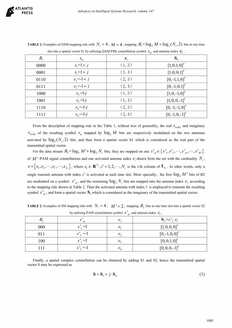
TABLE 1. Examples of GSM mapping rule with 4tN , 4M , mapping 1 2 2= log log ( , 2)tB M N bits at one time
slot into a spatial vector S1 by utilizing QAM/PSK constellation symbol ms and antenna index i .
1B ms i 1S
0000 1=1s j (1,3) [1,0,1,0]T
0001 1=1s j (1,4) [1,0,0,1]T
0110 2 =-1s j (2,3) [0, -1,1,0]T
0111 2 =-1s j (2,4) [0, -1,0,1]T
1000 3 =1-s j (1,3) [1,0, -1,0]T
1001 3 =1-s j (1,4) [1,0,0, -1]T
1110 4 =-1-s j (2,3) [0, -1, -1,0]T
1111 4 =-1-s j (2,4) [0, -1,0, -1]T
From the description of mapping rule in the Table 1, without loss of generality, the real Rems , and imaginary
,Imms of the resulting symbol ms mapped by 2log M bits are respectively modulated on the two antennas
activated by 2log ( ,2)tN bits, and then form a spatial vector S1 which is considered as the real part of the
transmitted spatial vector.
For the data stream 2 2 2= log ' log tB M N bits, they are mapped on one 1 2 '' ' , ' , , ' , , 'm m Ms s s s s
of 'M -PAM signal constellations and one activated antenna index 'ie drawn from the set with the cardinality tN ,
1 2 ', , , , ,ti Ne e e e e , where ' , ' 1, 2, ,tN
i te i N R is the i-th column of tNI . In other words, only a
single transmit antenna with index 'i is activated at each time slot. More specially, the first 2log 'M bits of B2
are modulated on a symbol 'ms , and the remaining 2log tN bits are mapped into the antenna index 'ie according
to the mapping rule shown in Table 2. Then the activated antenna with index i’ is employed to transmit the resulting
symbol 'ms , and form a spatial vector 2S which is considered as the imaginary of the transmitted spatial vector.
TABLE 2. Examples of SM mapping rule with 4tN , ' 2M , mapping 2B bits at one time slot into a spatial vector S2
by utilizing PAM constellation symbol 'ms and antenna index 'ie .
2B 'ms 'ie 2 2 '= ' is eS
000 1' =1s 1e [1,0,0,0]T
011 2' =-1s 2e [0, -1,0,0]T
100 1' =1s 3e [0,0,1,0]T
111 2' =-1s 4e [0,0,0, -1]T
Finally, a spatial complex constellation can be obtained by adding S1 and S2, hence the transmitted spatial
vector S may be expressed as
1 2j S S S (1)
Advances in Intelligent Systems Research, volume 147
1085
where = -1j denotes the imaginary unit.
Thus, it can be seen that B = B1 + B2 bits are transmitted simultaneously using ISM-Q/P scheme in r tN N
MIMO channel. Hence the transmitted maximum number of bits per ISM-Q/P symbol can be calculated as
2 2 2= log ,2 log log 't tN N MM (2)
At the receiver, the received spatial signal at the receive antennas is expressed as:
',1 ,Re ,2 ,Im= '
i i im m e mE s s j s SY H S N h h h N (3)
where 1rNC Y , r tN NC H represents the channel response matrix, each element of which obeys the
independent and identically distributed (i.i.d) complex-valued Gaussian random variables with zero mean and
variance 2h . 1rNC N denotes additive Gaussian white noise (AWGN) vector with zero mean and variance 2n .
ES denotes the transmitted power, ,i xh denotes the column fading channel h that corresponds to the antenna
activated by the x -th element of the index i , 'ieh denotes the column fading channel h that corresponds to the
'i -th activated antenna. Assuming that the perfect channel state information (CSI) can be retrieved at the receiver, after the ML
detection which performs the exhaustive search among the whole spatial symbol S , the estimated indexes and symbols are obtained as:
2
ˆ ˆ ˆ ˆ, ', , ' arg minm mi i s s Y E f S S (4)
where i , ˆ 'i , ˆms , ˆ 'ms are the detected value,
',1 ,Re ,2 ,Im( ) 'i i im m e mf s s j s S h h h .
PERFORMANCE ANALYSIS OF ISM-Q/P SCHEME
In this section, the BER performances and the squared minimum Euclidean distance (MED) are analyzed to demonstrate the outstanding performances of our proposed ISM-Q/P scheme.
From [10], we can derive the union bound of the average Bit Error Probability (ABEP) performances of the proposed ISM-Q/P scheme from the expectation of the conditional pairwise error probability (CPEP).
With the assumption of perfect CSI, the CPEP can thereby be calculated by
2 2
2 2
1 1
2
21
ˆ ˆ( ( ) ( ) | ) ( ( ) ( ) )
ˆ( ( ) ( ) | )
ˆ( ( ) ( ) )2
r r
r
N N
r r r rr r
N
r rr
P f f P E f E f
P E f E f
EQ f f
S S
S S
S
S S H Y S Y S
Y S Y S H
S S
(5)
where S is the detected value, Q () denotes the Gaussian Q function.
The closed form expression for the expectation of the CPEP can be given as [10]
Advances in Intelligent Systems Research, volume 147
1086
'1
0
1 '1- 1+ˆ( ( ) ( ))'2 2
r rN rN
r
r
N rP f f
r
S S (6)
where =1+
, is the mean of an exponential random variable, namely 2
2ˆ( ) ( )
4 r r
EE f f
S S S .
Then ABEP of the ISM-Q/P scheme can be derived as:
2 2
1 1
1 ˆ ˆ( ( ) ( )) ( ( ) ( ))2
m m
b v w v wmv w
P P f f e f fm
S S S S (7)
where ˆ( ( ) ( ))v we f fS S is the total number of erroneous bits associated with the corresponding PEP event.
Minimum Euclidean Distance
At high signal noise ratio (SNR), since the asymptotic system performance of ABEP is mainly determined by the worst-case PEP which corresponds to the squared MED between the spatial vectors S when employing the fixed receiver antennas.
Thereby, we further analyze the squared MED and compare the proposed scheme with SM, GSM, QSM, ESM schemes. It can be observed from Table 3 that the spatial symbols generated from ISM-Q/P scheme have the larger squared MED value than other schemes. Hence, the performance of ISM-Q/P scheme is more reliable than other schemes.
TABLE 3. the squared minimum ED value 2
minˆD S S for the proposed scheme and various scheme.
Schemes Nt = 4, η= 7 Nt = 8, η= 10 SM S’1=1 4/82
GSM S’2=-1 4/82 QSM S’3=1 2/10 ESM S4=-1 4/11.5
ISM-Q/P 0.5 0.5
NUMERICAL RESULTS AND DISCUSSIONS
In this section, Monte Carlo simulations are performed to investigate the BER performances in various schemes. Firstly, the analytical ABEP and the simulated BER results are compared, as shown in Fig. 2(a), in scenarios of
both , = 4,4t rN N , 7 bits/symbol with ( , ') (4, 2)M M and , = 8,4 8,8t rN N , , 10
bits/symbol with ( , ') (4, 2)M M . It can be observed from the figure that our derived BER at high SNR matches
well with the simulated BER for the different spectrum efficiency and antenna number, which verifies the effectiveness of our derivations.
Second, considering the different spectrum efficiency and transmit antennas, as shown in Fig. 2(b). In the
scenario of , = 4, 4t rN N , 7 bits/symbol, it could be observed that the BER performance of ISM-Q/P
outperforms 2 dB SNR gains over that of QSM, and approximately 3.8 dB SNR gains over that of SM at BER value
of 10-2. Another scenario of , = 8, 4t rN N , 10 bits/symbol, more about 3.8 dB SNR gains than that of
Advances in Intelligent Systems Research, volume 147
1087
QSM and more 6 dB SNR gains than that of SM at BER value of 10-2 are achieved owing to increasing the MSED from spatial domain.
(a)Simulation and theoretical BER (b)BER of ISM-Q/P, SM,QSM schemes (c) BER performance
among ISM-Q/P, SM/GSM, QSM, DSM, ESM.
FIG. 2. BER performance of ISM-Q/P with various schemes
Thirdly, in the scenario of , = 8,8t rN N , 10 bits/symbol, as shown in Fig. 2(c). Since exploiting
spatial transmit and receive diversity gain, it can be seen from the figure that ISM-Q/P achieves better performance than the other schemes such as SM with 128QAM, GSM with 64QAM, QSM with 16QAM, DSM with 4QAM, and ESM with 16QAM. ISM-Q/P can achieve 9 dB, 6 dB, 4 dB, approximately 1 dB SNR gains than SM, GSM, QSM, DSM/ESM at BER value of 10-3, respectively. Therefore, the spatial domain in MIMO channel is worth of further investigating and exploiting.
CONCLUSION
In this paper, we present a scheme of ISM-Q/P structure to further exploit the spatial diversity to enhance the reliability of the MIMO-based communication system. Owing to the larger MSED between the spatial vectors, our proposed scheme achieves better BER performance than other schemes. Furthermore, BER performance and MSED
Advances in Intelligent Systems Research, volume 147
1088
are analyzed. Finally, the numerical results demonstrate that our proposed scheme improves significantly the performance of the MIMO-based system.
ACKNOWLEDGEMENTS
This research was supported by South China Institute of Software Engineer GU, Guangdong in China under Grant No.ky201703.
REFERENCES
1. R. Mesleh, H. Haas, S. Sinanovic, C. W. Ahn, and S. Yun, “Spatial modulation,” IEEE Trans. Veh. Technol, vol. 57, no. 4, pp. 2228–2241, July 2008.
2. P. Wolniansky, G. Foschini, G. Golden, and R. Valenzuela, “V-BLAST: an architecture for realizing very high data rates over the rich-scattering wireless channel,” in Proc. International Symposium on Signals, Systems, and Electronics (ISSSE’98), Pisa, Italy, Sept. 1998, pp. 295–300.
3. A. Younis, N. Serafimovski, R. Mesleh, and H. Haas, “Generalised spatial modulation,” in Proc. 2010 Forty Fourth Asilomar Conference on Signals, System and Computers, Nov. 2010, pp. 1498–1502.
4. J. Wang, S. Jia, and J. Song, “Generalised spatial modulation system with multiple active transmit antennas and low complexity detection scheme,” IEEE Trans. Wireless Commun, vol. 11, no. 4, pp. 1605–1615, Mar. 2012.
5. J. Fu, C. Hou, W. Xiang, L. Yan, and Y. Hou, “Generalized spatial modulation with multiple active transmit antennas,” in IEEE Globecom Workshops, Dec. 2010, pp. 839–844.
6. T. Datta, H. S. Eshwaraiah, and A. Chockalingam, “Generalized Space-and-Frequency Index Modulation,” IEEE Trans. Veh. Technol, vol. 65, no. 7, pp. 4911–4924, July 2016.
7. R. Mesleh, S. S. Ikki, and H. M. Aggoune, “Quadrature spatial modulation,” IEEE Trans. Veh. Technol, vol. 64, no. 6, pp. 2738–2742, June 2015.
8. Z. Yigit and E. Basar, “Double spatial modulation: A high-rate index modulation scheme for MIMO systems,” in 2016 International Symposium on Wireless Communication Systems (ISWCS), Sept. 2016, pp. 347–351.
9. C.-C. Cheng, H. Sari, S. Sezginer, and Y. T. Su, “Enhanced spatial modulation,” IEEE Trans. Commun, vol. 63, no. 6, pp. 2237–2248, June 2015.
10. M. K. Simon and M. Alouini, Digital communication over fading channels. Wiley, USA: Wiley Series in Telecommunications and Signal Processing, 2nd edition, 2005.
Advances in Intelligent Systems Research, volume 147