IEEE TRANSACTIONS ON INSTRUMENTATION AND MEASUREMENT, VOL. IM-23, NO. 1, MARCH 1974 that the accuracy of the phasemeter SPI does not depend upon the signal-to-noise ratio when a < 1. For the realization of the sequential phasemeters, the only parameter which has to be known is K, as seen in (12). This parameter is determined by the input filters of signal y (t) receiver, and the computation of K does not cause any larger difficulties. It is easy to notice that in the case of accurate radio-signal phase-difference measure- ment (navigation, time service), we have to apply weak introductory filtering, because the instability of the filters causes measurement error, and the need for phase differ- ence measurement at a small signal-to-noise ratio is not rare. The optimal, unbiased, asymptotically efficient and nonsequential estimator x0 of the phase x is given by the formula [2] xo = arctan y(t) sin wotdt/ (t) coscootdt]. (44) The realization of the described sequential estimators, as well .as the nonsequential estimator xsp, is simpler in practice. The limitation causes some measurement infor- mation loss, but as it is shown in [2], the loss of informa- tion is negligible. REFERENCES [1] R. A. Krajewski, "The statistical analysis of the quadrature polarity-coincidence correlator," Arch. Automat. Telemech., vol. 18, no. 1, 1973. [2] R. A. Krajewski, "Impulse phasemeter error involved by the additive Gaussian disturbances," Ph.D. dissertation, Gdan'sk, Poland, 1971. [3] H. Crame6r, "Mathematical methods of statistics," PWN, Warszawa, 1958. [4] D. Middleton, An Introduction to Statistical Communication Theory. New York: McGraw-Hill, 1960. Inductive and Transformative Transducers with Short-Circuiting Ring ALBERT WECKENMANN Abstract-An ideal short-circuiting ring (R = 0) represents an infinite magnetic resistance for magnetic flux. A core of suitable shape allows an influence to be exercised upon the path of magnetic flux in a ferromagnetic circuit by displacing a short-circuiting ring. This fact may be utilized to construct transformative or inductive transducers. Two practical arrangements are described, and the effects on the characteristics of various parameters such as short- circuit resistance, core geometry, frequency of the energizing current, etc., are explained. The transducers examined attain a linearity error of 0.3 percent for displacement of 10 cm. The transducers, as de- scribed, do not show any wear, and the force of the short-circuiting ring exerted on the object of measurement remains a factor of 1000 below the force of the transducer used previously. Consequently, transducers (for linear travel or angular rotation) with short-cir- cuiting rings are suitable both for use as rugged shop instruments and for precision transducers in metrology and control. I. INTRODUCTION SENSORS for nonelectric quantities are increasing in usage in the age of automation [1], [2], [4]. Par- ticularly important are transducers used for medium lengths of travel (about 10 cm). The relation between the displacement and the resultant output voltage should be as nearly proportional as possible. Such transducers are used both with automatic machine tools and for indicating such Manuscript received June 25, 1973; revised November 13, 1973. The author is at D-8501 Altenberg, Nurenberger Strasse 12, Germany. things as valve positions, door positions, tank levels, and water level. In compensographs (both XY and Xt re- corders), transducers with particular precision are needed. Apart from sensitivity and linearity, resistance to wear and the force exerted by the transducer on the object of measurement are important characteristics. The methods previously used for large travels show a small linearity (inductive and transformative plunger-type instruments) or wear (all types of resistance transmitters), or resulting large forces occur (plunger instruments > 10-3 N). Capacitive transmitters for an effective travel of about 10 cm are not realizable practically, because the needed mechanical precision is not readily achievable. In this paper, a magnetic transducer is described which does not show any wear, obtains a linearity error of 0.3 percent with a displacement of 10 cm, and in which the force remains below 10-6 N and only a small mass is to be moved. II. THE SHORT-CIRCUITING RING In nearly all magnetic transducers in common use (inductive and transformative), a ferromagnetic core is moved, which necessarily results in large masses and large forces. Only with eddy-current transducers adapted to measure small displacements (millimeter range) is ad- vantage taken of the variation of the inductance of a coil caused by moving a copper plate in an axial direction. A generalization of this principle is the use of movable short- 67
Transcript
IEEE TRANSACTIONS ON INSTRUMENTATION AND MEASUREMENT, VOL. IM-23, NO. 1, MARCH 1974
that the accuracy of the phasemeter SPI does not dependupon the signal-to-noise ratio when a < 1.
For the realization of the sequential phasemeters, theonly parameter which has to be known is K, as seen in(12). This parameter is determined by the input filtersof signal y (t) receiver, and the computation of K does notcause any larger difficulties. It is easy to notice that inthe case of accurate radio-signal phase-difference measure-ment (navigation, time service), we have to apply weakintroductory filtering, because the instability of the filterscauses measurement error, and the need for phase differ-ence measurement at a small signal-to-noise ratio is notrare.The optimal, unbiased, asymptotically efficient and
nonsequential estimator x0 of the phase x is given by theformula [2]
xo = arctan y(t) sin wotdt/ (t) coscootdt]. (44)
The realization of the described sequential estimators, as
well .as the nonsequential estimator xsp, is simpler inpractice. The limitation causes some measurement infor-mation loss, but as it is shown in [2], the loss of informa-tion is negligible.
REFERENCES[1] R. A. Krajewski, "The statistical analysis of the quadrature
[2] R. A. Krajewski, "Impulse phasemeter error involved by theadditive Gaussian disturbances," Ph.D. dissertation, Gdan'sk,Poland, 1971.
[3] H. Crame6r, "Mathematical methods of statistics," PWN,Warszawa, 1958.
[4] D. Middleton, An Introduction to Statistical CommunicationTheory. New York: McGraw-Hill, 1960.
Inductive and Transformative Transducers with Short-Circuiting RingALBERT WECKENMANN
Abstract-An ideal short-circuiting ring (R = 0) represents aninfinite magnetic resistance for magnetic flux. A core of suitableshape allows an influence to be exercised upon the path of magneticflux in a ferromagnetic circuit by displacing a short-circuiting ring.This fact may be utilized to construct transformative or inductivetransducers. Two practical arrangements are described, and theeffects on the characteristics of various parameters such as short-circuit resistance, core geometry, frequency of the energizing current,etc., are explained. The transducers examined attain a linearity errorof 0.3 percent for displacement of 10 cm. The transducers, as de-scribed, do not show any wear, and the force of the short-circuitingring exerted on the object of measurement remains a factor of 1000below the force of the transducer used previously. Consequently,transducers (for linear travel or angular rotation) with short-cir-cuiting rings are suitable both for use as rugged shop instrumentsand for precision transducers in metrology and control.
I. INTRODUCTION
SENSORS for nonelectric quantities are increasing inusage in the age of automation [1], [2], [4]. Par-
ticularly important are transducers used for mediumlengths of travel (about 10 cm). The relation between thedisplacement and the resultant output voltage should be asnearly proportional as possible. Such transducers are usedboth with automatic machine tools and for indicating such
Manuscript received June 25, 1973; revised November 13, 1973.The author is at D-8501 Altenberg, Nurenberger Strasse 12,
Germany.
things as valve positions, door positions, tank levels, andwater level. In compensographs (both XY and Xt re-corders), transducers with particular precision are needed.Apart from sensitivity and linearity, resistance to wear andthe force exerted by the transducer on the object ofmeasurement are important characteristics. The methodspreviously used for large travels show a small linearity(inductive and transformative plunger-type instruments)or wear (all types of resistance transmitters), or resultinglarge forces occur (plunger instruments > 10-3 N).Capacitive transmitters for an effective travel of about 10cm are not realizable practically, because the neededmechanical precision is not readily achievable. In thispaper, a magnetic transducer is described which does notshow any wear, obtains a linearity error of 0.3 percentwith a displacement of 10 cm, and in which the forceremains below 10-6 N and only a small mass is to be moved.
II. THE SHORT-CIRCUITING RINGIn nearly all magnetic transducers in common use
(inductive and transformative), a ferromagnetic core ismoved, which necessarily results in large masses and largeforces. Only with eddy-current transducers adapted tomeasure small displacements (millimeter range) is ad-vantage taken of the variation of the inductance of a coilcaused by moving a copper plate in an axial direction. Ageneralization of this principle is the use of movable short-
67
IEEE TRANSACTIONS ON INSTRUMENTATION AND MEASUREMENT, MARCH 1974
_ _ _ _ _ _ _ _ _ _ _ _ _ _
V w=1000 1IIT
SR
0 I=llVcmFig. 1. Inductive transducer with short-circuiting ring. Cross
section of a core leg: 3 mm X 3 mm (15 sheets of Mumetal, 0.2mm thick).
circuiting windings on ferromagnetic circuits in the designof the transducer (or rotation angle transmitter). Onthe basis of the analogy between the electric and magneticcircuit, a short-circuiting coil (electric resistance to con-duction R; number of turns w) represents a positivereactance in the magnetic circuit with the value
Xm R (co: angular frequency). (1)
With skin effect neglected, a short-circuiting ring withconductor cross section aR will have the same effect as ashort-circuited winding (number of turns w, wire crosssection a,), if aK is equal to w*a,. On the idealizing supposi-tion that the short-circuiting ring does not show anyelectric resistance, the ring represents an infinite magneticreactance. The short-circuiting ring arranged to be mov-able on a ferromagnetic core, so as to represent a slidingmagnetic reactance, allows variation of the path of themagnetic flux. In this way, an inductive or a transformativetransducer may be designed.
III. THE INDUCTIVE TRANSDUCER WITHSHORT-CIRCUITING RING
One of the possible arrangements for an inductive trans-ducer with short-circuiting ring is shown in Fig. 1. On thecore without air gap and with the winding on the coreyoke, a plate of copper with holes for the core legs ismoved, i.e., each core limb is enclosed by a short-circuitingring. The location of the short-circuiting ring is charac-terized by s.On the ideal presuppositions that: 1) there is no leakage
flux with the short-circuiting ring in the position s = 0(i.e., L = 0 for s = 0); 2) there is no leakage flux aroundthe short-circuiting ring, leaving the core in front of theshort-circuiting ring and reentering behind it; 3) theelectric resistance of the short-circuiting ring is equal tozero; and 4) the permeability g, of the core material isinfinite, the effect of the transducer is explained in thefollowing discussion.The magnetic flux produced by the coil must close via
the core window between the coil and the short-circuitingring. The magnetic permeance A of the window betweenthe coil and the short-circuiting ring is linearly dependenton s. This means that the inductance is dependent linearlyon the position of the short-circuiting plate, giving
L = k-s. (2)
The factor of proportionality k is essentially a function ofthe core geometry, particularly of the window width.
The exactly linear characteristic represented by (2)will not be obtained when the ideal presuppositions 1-4are not fully met. Influences are as follows.
1) Around the coil there is always a leakage flux evenif the short-circuiting rings are in the position s = 0.The leakage flux results in a parallel displacement of thecharacteristic by LI, as seen by
L = k.s + Lr. (3)
2) Around the short-circuiting rings there is also aleakage flux which may be reduced by using a very largecopper plate, or increased by ferromagnetic sheets placedparallel to the core leg. If conditions 3 and 4 are effective,a leakage flux independent of the position also produces aparallel displacement of the characteristic by LII, asshown by
L = k.s + LI + LII. (4)3) When the electric resistance R of the short-circuiting
rings is not exactly zero, a positive reactance j(wIR)must be included when computing the characteristic. Withthe condition IA,, -+ oo, this leads to the equation
L = k.s +R+ LI + LII.
Jw(5)
Particularly at lower frequencies, a finite resistance of theshort-circuiting plate for small s results in a curvature tothe left, whereby L(s = 0) increases. To obtain a charac-teristic linear for a large range, the electric resistance of theshort-circuiting ring must be kept low, and the frequencymust be selected as high as possible.
4) The influence of a finite complex permeability, alsodependent on the frequency, cannot be given by a simpleformula, but a closed computation of the characteristic ispossible, especially with a rectangular core. The influenceof the finite permeability may be clearly explained bysaying that the magnetic resistance of the core legs isadded to the resistance of the core window. The result isthat the permeance provided to close the magnetic fluxincreases less than proportionally to s. Consequently, thecharacteristic has a curvature to the left, especially forlarge values of s. For a linear characteristic, the permea-bility of the core material must be as large as possible,which is obtained with a given core material and constantfrequency by using extremely thin core laminations.Thus there are two opposite requirements. On the one
hand, a low frequency should be selected to obtain therequired permeability of the ferromagnetic sheets. On theother hand, the frequency should be high to keep low theinfluence of the finite resistance of the short-circuiting ring.It is expected that optimal linearity may be obtained withan intermediate frequency (see Fig. 2 and Table I.)
Fig. 2 shows the characteristic L = f(s) measured fordifferent frequencies. Measurements were carried out witha core arranged in layers of 15 Mumetal sheets of 0.2 mminsulated from each other. (The core may be also of ferritematerial, but the permeability of the ferrites, approxi-mately independent of the frequency, is lower than that
68
WECKENMANN: INDUCTIVE AND TRANSFORMATIVE TRANSDUCERS
I1 W, = 620 1_,% L\k;XEE \XI lll T
V2 =w300 1,4cm
SR0 11,7cm 5
0
Fig. 2. Characteristics L
5cm 10 cm
= f(s), given by the transducer accordingto Fig. 1.
Fig. 3. Transformative transducer with short-circuiting ring. Crosssection of a core leg: 5 mm X 5 mm (25 sheets of Mumetal, 0.2mm thick).
flowing through the windings between the initial winding(s = 0) and the position of the short-circuiting ring, i.e.,the magnetic circulation responsible for the yoke fluxincreases proportionally to s. The magnetic permeance ofthe core window designed to close the flux also increasesproportionally to s. The exact computation gives thecharacteristic equation
V2 =k- S9-I,. (6)
TABLE ILINEARITY ERROR OF MEASURED CHARACTERISTICS OF THE
INDUCTIVE TRANSDUCER
Frequency Linearity Error(Hz) (percent)
300 8500 2800 0.81000 0.91500 2
a
of the sheets.) The overall dimensions of the core are
120 mm X 15 mm, with the limb width being uniformly3 mm, and the coil having 1000 turns. Table I shows thelinearity error for different frequencies. With the experi-mental arrangement, optimum linearity is obtained at800 Hz. The force on the short-circuiting plate remainsbelow 2. 10-6 N over the whole length.
IV. THE TRANSFORMATIVE TRANSDUCERWITH SHORT-CIRCUITING RING
In addition to the inductive transducer, a transformativetransducer with short-circuiting ring may be designed(see Fig. 3). On one leg of the long-shaped enclosedrectangular core made of single sheets arranged in layers,there is the primary coil, .as a single layer winding, evenlydistributed over the whole length. On the other core leg a
short-circuiting ring is moved. The secondary coil ismounted on the core yoke. The sinusoidal alternatingcurrent I, through the primary coil is low enough tomagnetize the ferromagnetic core only in the initial range;
the secondary current A is zero. Under the ideal conditionsthat the electric resistance of the short-circuiting ring iszero, there is no leakage flux escaping in front of the short-circuiting coil from the core and then reentering behind it,and the permeability of the core is co. The effect may beexplained in the following discussion.The flux through the core yoke with the secondary coil
mounted thereupon is produced by the energizing current
The constant ki is determined essentially by the windingdensity and the window width.
Including the magnetic permeance A, parallel to theshort-circuiting ring for the leakage flux, around the short-circuiting ring and the finite electric resistance R of theshort-circuiting ring, the characteristic equation obtainedis
Equation (7) discloses that a linear characteristic may beobtained with a suitable selection of Ap = Ap(s). Whenusing only one short-circuiting ring, as described, A, be-comes a function of the location, since the governing inputand output surfaces for the leakage flux depend on theplace of the short-circuiting ring. Through this positionaldependency, an approximately linear characteristic is ob-tained. Further possibilities ofInfluencing A, are offered byproviding ferromagnetics or surfaces having good con-
ducting properties.When the finite complex permeability of the core
material (dependent on frequency) is taken into account, a
closed computation of the characteristic is practical, but itwill be very extensive and complex. In principle, the same
tendency as with the inductive transducers appears. Thefinite permeability results in the characteristic for large s
having a curvature to the right.Fig. 4 shows the characteristics measured experi-
mentally with constant energizing current II. With lowfrequency, the finite resistance of the short-circuiting ringis responsible for the poor linearity for small values of s,
whereas with high frequency, the low permeability forlarge values of s results in a poor linearity. Table II showsthe linearity error of the measured characteristics withdifferent frequencies noted with displacements of As = 10cm. With about 4 kHz, an optimum linearity of 0.5 percentappears. The reason the frequency of optimum linearityis much higher than that with the inductive transducer isthat the linear characteristic of the transformative trans-ducer is obtained through nonideal conditions from a
L
2H
O Hz
10 kHz
69
IEEE TRANSACTIONS ON INSTRUMENTATION AND MEASUREMENT, MARCH 1974
V2
=0)0.5 V-
O0-0.1 1 10 100 1000 R 2/kQ
Fig. 6. Maximum voltage (V2(s = 1)) and minimum voltage(V2(s = 0)) plot as a function of secondary coil load R2 takenup with the transducer according to Fig. 3 (I, = 1 mA).
Fig. 4. Measured characteristics V2 = f(s) of the transduceraccording to Fig. 3 (II = 1 mA).
TABLE IILINEARITY ERROR OF MEASURED CHARACTERISTICS OF THE
TRANSFORMATIVE TRANSDUCER
Frequency Linearity Error(kHz) (percent)
2 1.23 0.84 0.55 0.87 1.1
v2 t
ikHz
kHz
U0 5 Cm 10cm
Fig. 5. Measured characteristics V2 = f(s) of the transformativetransducer with generator source resistance zero. Standardized onthe same voltage difference, AV2 = V2(s 1) - V2(s = 0);(V1 = 1.46 V).
characteristic which is a quadratic in the ideal case, so some
compensation occurs. The inductive transducer requiresconditions to be as ideal as possible.
Since the primary coil represents a variable load for thegenerator when the short-circuiting ring is moved, theinternal resistance of the generator of current I, must be as
large as possible, if a linear characteristic is to be obtained.In Fig. 5, some measured curves are shown with the in-ternal generator resistance at zero. For these measure-
ments, the same voltage difference AV (zAV = V2 (s = 1)-V2(s = 0)), was adopted to make the variations clear.The load resistance of the secondary side is also relevantto the shape of the characteristic when the secondary coilis loaded, because linearity gets lost. Fig. 6 shows the
V2
V
0 5cm 10cm
Fig. 7. Measured characteristics V2 = f(s) with concentratedexciting coil of 300 windings (I, = 1 mA, core shape accordingto the transducer of Fig. 3); Va is the coil at s = 0, Vb is the coilat s = 1/2, and V, is the coil at s = 1.
variations of the voltages V2(s = 0) and V2 (S = 1) as
functions of load resistance. With decreasing load resist-ance, the linearity of the V2(s) characteristic will changefor the worse. Since influence of load resistance is com-
parable to the influence of low permeability, it will bepossible to nearly restore the original linearity of thecharacteristic by reducing the frequency, which results inan increase of permeability.When using concentrated exciting coils (300 windings)
located at s = 0, s = 1/2, or s = 1, the characteristicsplotted in Fig. 7 are obtained. It is remarkable that in thecase of the single coil at s = 1, the positionally dependentpermeance Ap(s) for the leakage flux around the short-circuiting ring is measured in parallel with the constantmagnetic reactance of the imperfect short-circuiting ring.By such additional concentrated exciting coils, it ispossible to purposively improve the linearity of thecharacteristic.The effect on the characteristic, by means of different
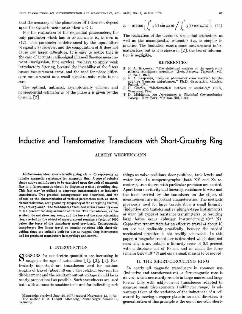
core shapes, is shown in Fig. 8. Modified core shapes to-gether with single concentrated exciting coils offer theopportunity to produce nearly any sha.pe of characteristicrequired (for example, logarithmic for limited ranges).With the transformative transducer, a differential
arrangement using two secondary coils on the core yokesmay be constructed. The sensitivity is doubled and thelinearity is improved.
V2
1V+
,13 kHz
,10 kHz
,75kHz
0
, 5 kHz
- 3SkHz
- 2kHz
- 1kHz
-I
5cm 10cm
u, .. .I
n
70
WECKENMANN: INDUCTIVE AND TRANSFORMATIVE TRANSDUCERS
V2
lv +
0
15cm 10cm S
C
A
Fig. 8. Qualitative characteristics V2 = f (s), taken up withmodified core shapes.
After rectification of the difference voltage by means ofa synchronous rectifier, the output voltage will assumepositive and negative values, so as to transfer the mechani-cal zero into the center of the configuration. To a displace-ment of As = 10 cm with the differential configuration alinearity error of 0.3 percent, and with As = 0.2 cm a linear-ity of 6 percent is obtained. Since the characteristic at zeroshows a point of inflection, the linearity error for smallerdisplacements will rapidly decrease. It seems to be quitepossible to operate the differential arrangement with asuitable core shape and corresponding short-circuiting ringwith line frequency and still obtain good results.
It is also possible, in lieu of the closed core, to use anopen core where the wound coil may be put upon the core.With nonsinusoidal energizing current, other forms of
characteristic are obtained, due to the harmonic contentand the dependence of permeability on frequency.
V. CONCLUSION
The short-circuiting ring a component having hadlittle attention until now allows us to construct inductiveand transformnative transducers in a very simple way. Thecore sections shown in this paper present but a few of themany practicable core geometries. An example of anothertransformative transducer with short-circuiting ringpresenting quite another flux course is given in [3].
Transducers with short-circuiting rings are distinguished
by high ruggedness because they do not show any wear andall parts may be provided with plastic coatings for use in acorrosive environment. The force exerted by the trans-ducer upon the measuring object is extremely low; it isin the range of 10-6 N, or below 10-7 N with inductivedifferential transducers. The typical comparative valuewith the plunger transducer is 10-3 N. The short-circuitingring of suitable construction has a mass of only about1-2 g, so that it cannot misrepresent the result even withdynamic measurements. The core for simple coil mountingmay also be disposed in layers of open sheets. The sensi-tivity of the inductive transducer constructed experi-mentally was about 2 mH/mm. With the transformativetransducer, a sensitivity of about 10 mV/,mm was reached.This may easily be augmented to 100 mV/mm by raisingthe number of secondary turns and increasing the current.The installation length is only 20 percent longer than theeffective displacement, which may be of importance withlimited space availability. (In comparison with the plungertransducer, installation length is triple the effective dis-placement.) The mechanical precision required for produc-tion does not present any problems, for the optimumlinearity in the ready-mounted transducer is obtained bysetting the proper frequency. The constancy of the fre-quency and the energizing current as well must be adaptedto the precision required. The linearity obtained may beimproved by another core shape, another core material, orby additional ferromagnetic sheets of suitable shape, sothat a linearity of 0.05 percent on 10-cm displacementseeins to be quite realizable. By means of purposive varia-tion of parameters, quite another shape of characteristicmay be produced. With a suitable core shajpe and windingdistribution, the method may be used for rotating angletransmitters. Because of its excellent properties, the trans-ducer with short-circuiting ring is superior to the othermethods of analog transducers presently used for dis-placements in the 10-cm range (from about 3 to about25 cm). The method is of particular interest in precisionindustrial measuring instruments, but it is suitable alsofor the simplest transducers for operation with line fre-quency.
REFERENCES[1]
[21[3]
[4]
H. K. P. Neubert, Instrument Transducers. London: Oxford,1963.T. G. Beckwith and N. L. Buck, Mlechanical Measurements.Reading, Mass.: Addison-Wesley, 1961.Prospectus of Clevite Corporation, Brush Instruments Division,Cleveland, Ohio.Ch. Itohrbach, Handbuchffur Elektrisches. Messen MechanischerGrossen, VDI-Verlag, Dusseldorf, 1967.