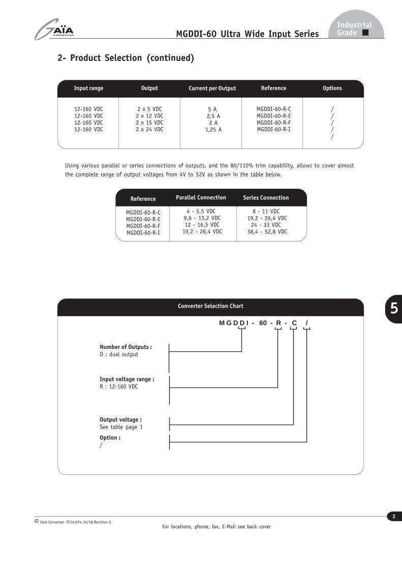
C : 2 x 5 VDCE : 2 x 12 VDCF : 2 x 15 VDCI : 2 x 24 VDC
Output
The MGDDI-60 ultra wide input series designatesa full family of DC/DC power modules designedfor use in distributed power architecture wherevariable input voltage for multiple battery andtransient are prevalent making them idealparticularly for transportation/mass transit,railways or high-end industrial applications. Thesemodules use a high frequency fixed swichingtopology at 270KHz providing excellent reliability,low noise characteristics and very high efficiencyover the entire input voltage range.Standard models are available with a permanentultra wide input voltage range of 12-160 voltsfully compatible with 24V/36V/72V/110V/125Vbattery applications. The serie includes dual out-put voltage choices individually isolated of 2 x 5volts , 2 x 12 volts, 2 x 15 volts and 2 x 24 voltswith easy configurability.
Permanent
R : 12-16O VDC
12:1 Ultra Wide InputDual Outputs
Metallic Case - 2 250 VDC Isolation
The MGDDI-60 serie is designed in conformitywith safety standards EN60950.All the modules are designed with LC networkfilters to minimize reflected input current rippleaccording to ease EN55022 standard.The modules include a soft-start, an inputundervoltage lock-out, a permanent short cir-cuit protection, a thermal protection and an out-put overvoltage limitation to ensure efficient mo-dule protections. The soft-start allows currentlimitation and eliminates inrush current duringstart-up. The short circuit protection completelyprotects the modules against short-circuits ofany duration by a shut-down and restores tonormal when the overload is removed.
3- Electrical SpecificationsData are valid at +25°C, unless otherwise specified.
Note : Modules have to be mounted with heatsink for electrical tests..
Note (1) : From 12V to 14V and from 140V to 160V a derating of 66% of total maximum permanent power should be observed.Note * : Regulation is measured with both outputs in parallel configuration.
Note ** : The ripple output voltage is the periodic AC component imposed on the output voltage, an aperiodic and random component (noise) has also to be considered.This noise can be reduced by adding 1 external decoupling capacitor connected between Gin and Gout. These capacitance should be layed-out as close as possible from
the converter. The ripple output voltage is measured by connecting a ceramic chip capacitor Co accross Vo and Go pins (C=100µF if Vo<5Vdc C=10µF if Vo>5Vdc).
Parameter ConditionsLimit ortypical
Units Dual Output
MGDDI-60 - R
Input
Nominal input voltage Full temperature range Nominal VDC 48
Permanent inputvoltage range (Ui)
Full temperature rangeFull load see note (1)
Min. - Max. VDC 12-160
Undervoltage lock-out(UVLO)
Turn-on voltage (pin Uvlo open)Turn-off voltage (pin Uvlo open)
MaximumMaximum
VDCVDC
11,810,8
Start up timeUi nominal within 3 msNominal outputFull load : resistive
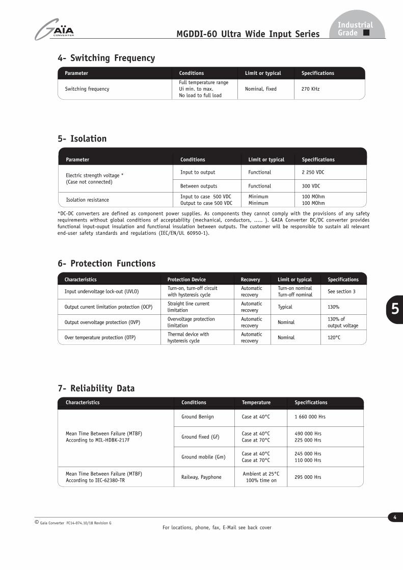
Over temperature protection (OTP)Thermal device withhysteresis cycle
Automaticrecovery
Nominal 120°C
7- Reliability Data
Parameter Conditions Limit or typical Specifications
Switching frequencyFull temperature rangeUi min. to max.No load to full load
Nominal, fixed 270 KHz
5- Isolation
Characteristics Conditions Temperature Specifications
Mean Time Between Failure (MTBF)According to MIL-HDBK-217F
Ground Benign Case at 40°C 1 660 000 Hrs
Ground fixed (Gf)Case at 40°CCase at 70°C
490 000 Hrs225 000 Hrs
Ground mobile (Gm)Case at 40°CCase at 70°C
245 000 Hrs110 000 Hrs
Mean Time Between Failure (MTBF)According to IEC-62380-TR
Railway, PayphoneAmbient at 25°C100% time on
295 000 Hrs
Parameter Conditions Limit or typical Specifications
Electric strength voltage *(Case not connected)
Input to output Functional 2 250 VDC
Between outputs Functional 300 VDC
Isolation resistanceInput to case 500 VDCOutput to case 500 VDC
MinimumMinimum
100 MOhm100 MOhm
*DC-DC converters are defined as component power supplies. As components they cannot comply with the provisions of any safetyrequirements without global conditions of acceptability (mechanical, conductors, ..... ). GAIA Converter DC/DC converter providesfunctional input-ouput insulation and functional insulation between outputs. The customer will be responsible to sustain all relevantend-user safety standards and regulations (IEC/EN/UL 60950-1).
Configuration With a common mode capacitor C c = 10 nFand external filterModels
All models Class B
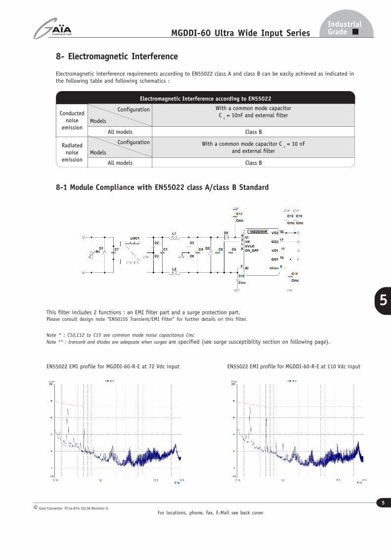
8- Electromagnetic Interference
Electromagnetic interference requirements according to EN55022 class A and class B can be easily achieved as indicated inthe following table and following schematics :
8-1 Module Compliance with EN55022 class A/class B Standard
EN55022 EMI profile for MGDDI-60-R-E at 72 Vdc input EN55022 EMI profile for MGDDI-60-R-E at 110 Vdc input
Note * : C10,C12 to C15 are common mode noise capacitance Cmc
Note ** : transorb and diodes are adequate when surges are specified (see surge susceptibility section on following page).
This filter includes 2 functions : an EMI filter part and a surge protection part.Please consult design note ‘’EN50155 Transient/EMI Filter’’ for further details on this filter.
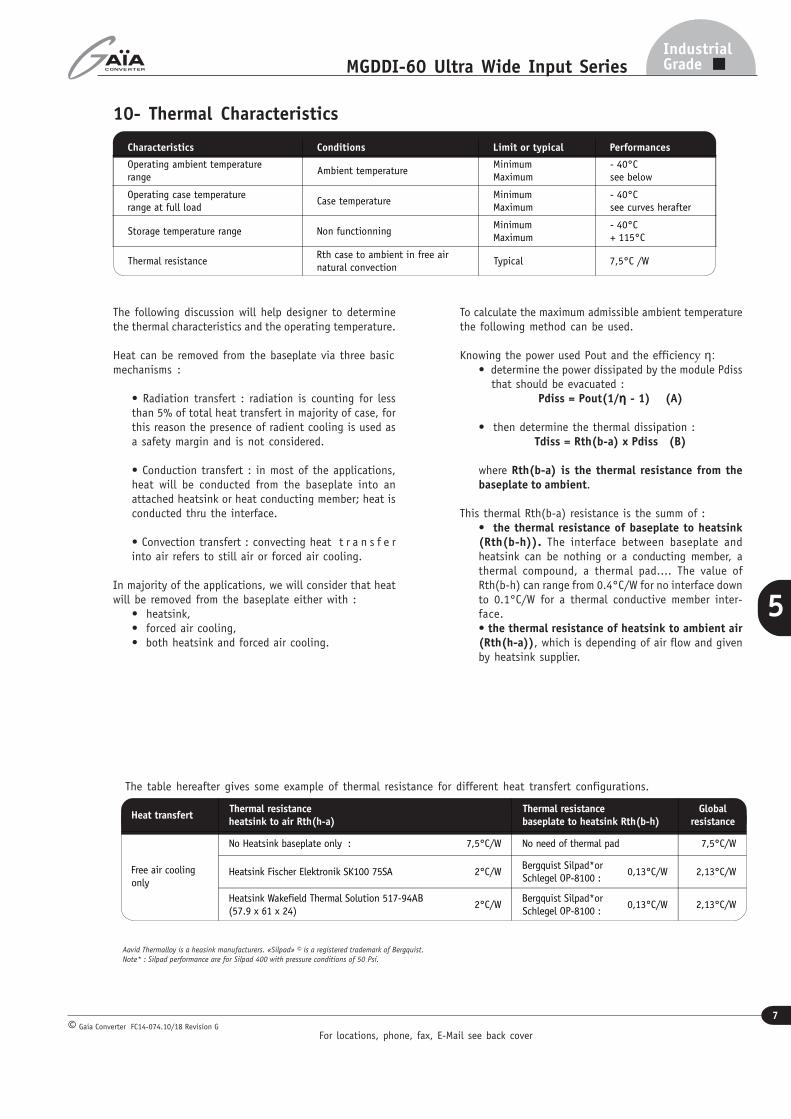
Characteristics Conditions Limit or typical Performances
Operating ambient temperaturerange
Ambient temperatureMinimumMaximum
- 40°Csee below
Operating case temperaturerange at full load
Case temperatureMinimumMaximum
- 40°Csee curves herafter
Storage temperature range Non functionningMinimumMaximum
- 40°C+ 115°C
Thermal resistanceRth case to ambient in free airnatural convection
Typical 7,5°C /W
The following discussion will help designer to determinethe thermal characteristics and the operating temperature.
Heat can be removed from the baseplate via three basicmechanisms :
• Radiation transfert : radiation is counting for lessthan 5% of total heat transfert in majority of case, forthis reason the presence of radient cooling is used asa safety margin and is not considered.
• Conduction transfert : in most of the applications,heat will be conducted from the baseplate into anattached heatsink or heat conducting member; heat isconducted thru the interface.
• Convection transfert : convecting heat t r a n s f e rinto air refers to still air or forced air cooling.
In majority of the applications, we will consider that heatwill be removed from the baseplate either with :
• heatsink,• forced air cooling,• both heatsink and forced air cooling.
To calculate the maximum admissible ambient temperaturethe following method can be used.
Knowing the power used Pout and the efficiency η:• determine the power dissipated by the module Pdiss that should be evacuated :
Pdiss = Pout(1/ηηηηη - 1) (A)
• then determine the thermal dissipation :Tdiss = Rth(b-a) x Pdiss (B)
where Rth(b-a) is the thermal resistance from thebaseplate to ambient.
This thermal Rth(b-a) resistance is the summ of :• the thermal resistance of baseplate to heatsink(Rth(b-h)). The interface between baseplate andheatsink can be nothing or a conducting member, athermal compound, a thermal pad.... The value ofRth(b-h) can range from 0.4°C/W for no interface downto 0.1°C/W for a thermal conductive member inter-face.• the thermal resistance of heatsink to ambient air(Rth(h-a)), which is depending of air flow and givenby heatsink supplier.
The table hereafter gives some example of thermal resistance for different heat transfert configurations.
The MGDD-60 series includes 4 types of protection devices.
12-1 Input Undervoltage Lockout (UVLO)An input undervoltage protection will inhibit the module wheninput voltage drops below the lock-out turn-off threshold (see sec-tion 3 for value) and restores to normal operation automaticallywhen the input voltage rises the lock-out turn-on threshold.
The UVLO voltage can be adjusted using a resistor (Ruvlo) connectedbetween pin (1) and GIA. This value can be ajusted in order toallow converter to stops properly accordingly to the input bus (orbattery) voltage value. The Ruvlo can be determined using thefollowing formula :Ruvlo (KΩ) = [200.3-Vuvlo]/[Vuvlo-11.8]Ruvlo = trimming resistanceVuvlo = desire turn-on voltage
Without resistor, the turn on voltage is 11.8V and turn off voltageis 10.8V
12-2 Output Over Current Limitation Protection (OCP)The MGDD-60 Series incorporates a overcurrent protection circuit.The overcurrent protection detects short circuit or over curentand protects the module according to the hiccup graph . Themaximum detection current Id is depending on input voltage Vin,temperature, and is higher than 105 % maximum nominal outputcurent.When OCP is triggered, the converter falls in hiccup mode bytesting periodically if the overload is still present. The modulerestart automatically in soft-start to normal operation whenovercurrent is removed. Td (detection time) and Th (hiccupperiod) are depending on Vin and temperature. In hiccup modethe average curent is arround 25 % of Inom.
12-3 Output Overvoltage Protection (OVP)The MGDD-60 series has an internal overvoltage limitation protec-tion circuit that monitors the voltage accross the output powerterminals. It is designed to limit the converter output voltageto 130% (+/-10%) of nominal output voltage.
12-4 Over Temperature Protection (OTP)A thermal protection device adjusted at 120°C (+/-5%) internaltemperature with 10°C hysteresis cycle will inhibit the module aslong as the overheat is present and restores to normal operationautomatically when overheat is removed. The efficiency of the OTPfunction is warranty with the module mounted on a heatsink.
13-1-1 Connection of Outputs in SeriesOutputs connected in series allow to achieve 10V, 24V,30V or 48V output voltages up to 60W total power. Thesevalues can be extended using trim adjustment.
13-1-3 Connection of Outputs in SymmetryOutputs connected in symmetry allow to achieve +/-5V,+/-12V, +/-15V or +/-24V voltages (+/-30W each)with possible unbalanced loadup to 50W on primaryoutput, 10W on secondary output and vice versa.
13- Description of Functions13-1 Connection of OutputsThe outputs of MGDDI-60 can be connected in various configurations such as :
- connections in series- connection in parallel- connection in symmetry- connection in independance
Please note that regulation is achieved through output V01/G01 referenced as primary output. When connected in symetrieor independant configurations with unbalanced loads, VO1/GO1 has to be loaded at 6W minimum to insure proper operatingof the converter. The V02/G02 output referenced as secondary output may stay unloaded, but in that case its regulation maydrift up as shown in curve below. There is no minimum load when the two outputs are connected in parallel or balanced serie.
Outputs connected independantlywith floating DC between eachother can be achieved for 2x5V,2x12V, 2x15V or 2x24V voltages(30W each) with possibleunbalanced load up to 50W onprimary output 10W on secondaryoutput and vice versa.
13-1-2 Connection of Outputs in ParallelOutputs connected in paralell allow to achieve single output5V, 12V, 15V or 24V up to 60W power. These values can beextended using trim adjustment.
The control pin 8 (On/Off) can be used for applications requiringOn/Off operation. This may be done with an open collectortransistor, a switch, a relay or an optocoupler. Severalconverters may be disabled with a single switch by connectingall On/Off pins together.
• The converter is disabled by pulling low the pin 8.• No connection or high impedance on pin 1 enables theconverter.
By releasing the On/Off function, the converter will restartwithin the start up time specifications given in table section 3
Parameter Unit Min. Typ. Max. Notes, conditions
On/Off module enable voltage Vdc 2.1 / 3.3 Open, the switch must not sink more than 50µA
On/Off module disable voltage Vdc 0 / 0.5 The switch must be able to sink 0,5mA
On/Off alarm level Vdc 0 / 0.5 OTP faulty module
On/Off module enable delay ms / / 30 The module restarts with the same delay after alarm mode removed
On/Off module disable delay µs / / 100 Vi nominal, full load
13-4 Input Filter Compensation (VIF)
The «VIF» pin is a direct access to the capacitor of the LCinput filter and allows to increase the C value to enhancethe converter’s stability and performance and to reduce theinput current ripple for improved EMI performance.It isrecommended to provide low ESR ceramic capacitors, totalvalue can rate from 2.2µF for high input voltage use to 10µFfor low input voltage use.These capacitors should have theproper voltage rating. Because of high current flowing throughit, it should be connected between «VIF» and «Gin» as closeas possible from the converter, using large copper traces.
The capacitor on Vif helps reducing conducted EMI level : thedifference between bleue green curve beside highlights theeffect of VIF capacitor.
Dimension are given in mm. Tolerance : +/- 0,2 mm (+/- 0.01 “) unless otherwise indicated.Weight : 100 grams (3.6 Ozs) max.
15- Materials
Case : Metallic black anodized coating.Pins : Flash gold plating over nickel underplate.
16- Product Marking
Upper face : Company logo.Side face : Module reference, option, date code : year and week of manufacturing.
The MGDDI-60 series has been designed for on-board mounting.it is recommended not to lay-out any component under the module.
Keep out area
Information given in this datasheet is believed to be accurate and reliable. However, no responsibility is assumed for the consequence of its use nor for any infringement of patents or other rights of third parties which may result from its use.These products are sold only according to GAIA Converter general conditions of sale, unless otherwise confirmed by writing. Specifications subject to change without notice.
Prin
ted
in F
ranc
e by
GAIA
Con
vert
er G
aia
Conv
erte
r F
C14-
074.
03/1
8 Re
visi
on F
. Gr
aphi
sme
: Ph
ilipp
e Cl
icq
Represented by :
For more detailed specifications and applications information, contact :
International HeadquartersGAÏA Converter - France
ZI de la Morandière33185 LE HAILLAN - FRANCETel. : + (33)-5-57-92-12-80Fax : + (33)-5-57-92-12-89
North American HeadquartersGAÏA Converter Canada, Inc4038 Le Corbusier BlvdLAVAL, QUEBEC - CANADA H7L 5R2Tel. : (514)-333-3169Fax : (514)-333-4519