Directional Control Valves Catalog HY14-2502/US 2502-A6.p65, dd A A151 Parker Hannifin Corporation Hydraulic Valve Division Elyria, Ohio, USA Mounting Pattern NFPA D10 , CETOP 10, NG32 Maximum Operating Pressure 207 Bar (3000 PSI) Standard CSA 207 Bar (3000 PSI) Maximum Tank Line Pressure Internal Drain Model: 102 Bar (1500 PSI) Standard 207 Bar (3000 PSI) Optional External Drain Model: 207 Bar (3000 PSI) CSA 102 Bar (1500 PSI) Maximum Drain Pressure 102 Bar (1500 PSI) Standard 207 Bar (3000 PSI) Optional CSA 102 Bar (1500 PSI) Minimum Pilot Pressure 4.4 Bar (65 PSI) Maximum Pilot Pressure 207 Bar (3000 PSI) Standard CSA 207 Bar (3000 PSI) Nominal Flow 378 Liters/Min (100 GPM) Maximum Flow See Quick Reference Chart General Description The D101VW is a five-chamber, pilot operated, solenoid controlled, directional control valve. It is available in 2 or 3-position styles. They are manifold or subplate mounted valves, which conform to NFPA's D10/CETOP 10 mounting pattern. Operation Parker pilot operated valves are standard with low shock spools and pilot orifice. The orifice can be removed if a faster shift is required. However, it is recommended that all systems operating above 2000 PSI use the standard valve to avoid severe shock. Features • Low pressure drop design • Hardened spools provide long life • Fast response option available • Wide variety of voltags and electrical connection options • Explosion proof availability • No tools required for coil removal • Repairable manual override for easy seal replacement A Technical Information Series D101VW Specifications Response Time Nominal response times (milliseconds) are measured at 205 Bar (3000 PSI) and 416 L/M (110 GPM) with various pilot pressures as indicated. Solenoid Pilot Pull-In Drop-Out Type Pressure Std Fast Std Fast 500 180 170 195 195 DC 1000 130 125 195 195 2000 100 95 195 195 500 140 130 185 185 AC 1000 90 85 185 185 2000 60 55 185 185 Because of the high drain line pressure transients generated during shifting, use of the fast response option is not recommended for pilot pressures exceeding 205 Bar (2000 PSI). ▲ ▲
Transcript
Directional Control ValvesCatalog HY14-2502/US
2502-A6.p65, dd
A
A151 Parker Hannifin CorporationHydraulic Valve DivisionElyria, Ohio, USA
Mounting Pattern NFPA D10 , CETOP 10,NG32
Maximum OperatingPressure 207 Bar (3000 PSI) Standard
CSA 207 Bar (3000 PSI)
Maximum Tank LinePressure Internal Drain Model:
102 Bar (1500 PSI) Standard207 Bar (3000 PSI) OptionalExternal Drain Model:207 Bar (3000 PSI)
CSA 102 Bar (1500 PSI)
Maximum DrainPressure 102 Bar (1500 PSI) Standard
207 Bar (3000 PSI) Optional
CSA 102 Bar (1500 PSI)
Minimum PilotPressure 4.4 Bar (65 PSI)
Maximum PilotPressure 207 Bar (3000 PSI) Standard
CSA 207 Bar (3000 PSI)
Nominal Flow 378 Liters/Min (100 GPM)
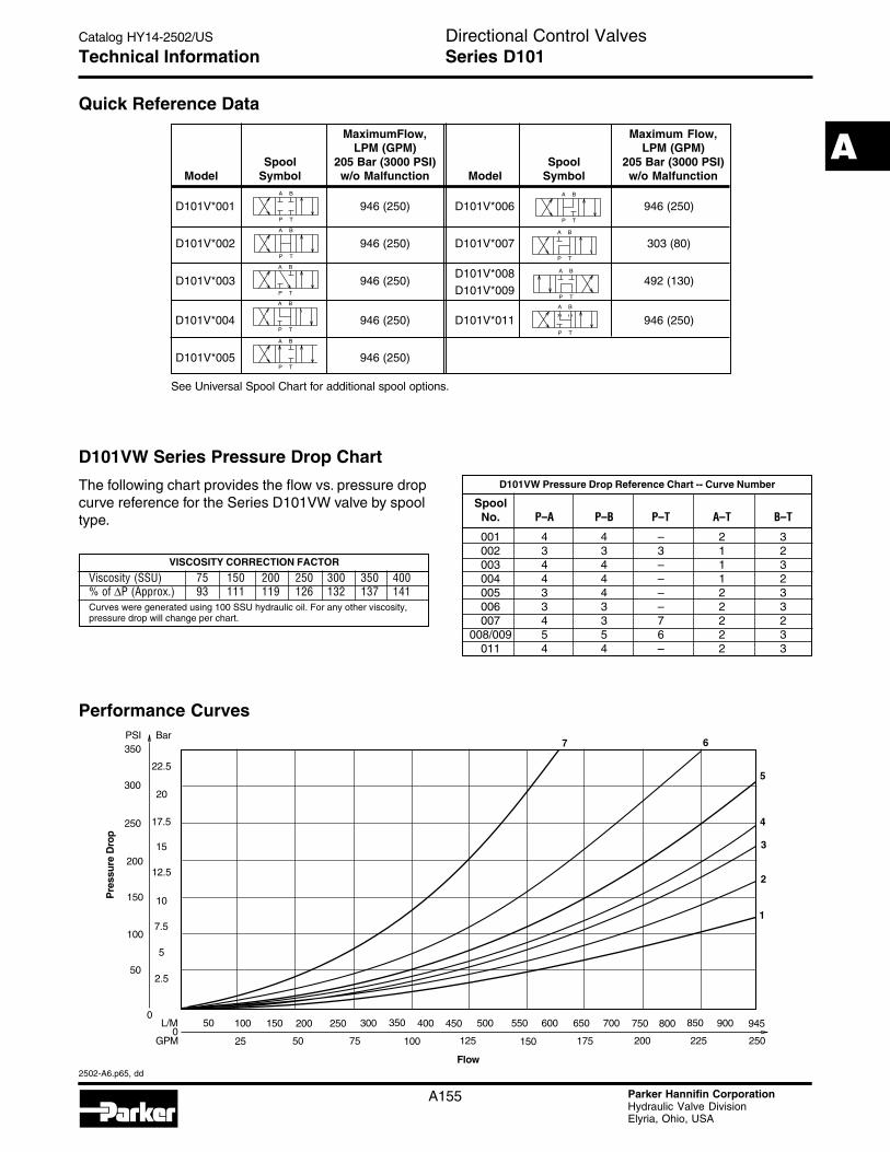
Maximum Flow See Quick Reference Chart
General Description
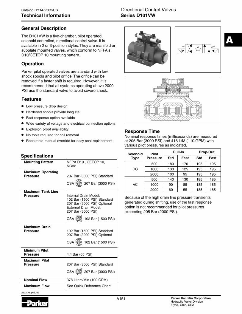
The D101VW is a five-chamber, pilot operated,solenoid controlled, directional control valve. It isavailable in 2 or 3-position styles. They are manifold orsubplate mounted valves, which conform to NFPA'sD10/CETOP 10 mounting pattern.
Operation
Parker pilot operated valves are standard with lowshock spools and pilot orifice. The orifice can beremoved if a faster shift is required. However, it isrecommended that all systems operating above 2000PSI use the standard valve to avoid severe shock.
Features
• Low pressure drop design
• Hardened spools provide long life
• Fast response option available
• Wide variety of voltags and electrical connection options
• Explosion proof availability
• No tools required for coil removal
• Repairable manual override for easy seal replacement
A
Technical Information Series D101VW
Specifications
Response TimeNominal response times (milliseconds) are measuredat 205 Bar (3000 PSI) and 416 L/M (110 GPM) withvarious pilot pressures as indicated.
Because of the high drain line pressure transientsgenerated during shifting, use of the fast responseoption is not recommended for pilot pressuresexceeding 205 Bar (2000 PSI).
▲
▲
Directional Control ValvesCatalog HY14-2502/US
2502-A6.p65, dd
A
A152 Parker Hannifin CorporationHydraulic Valve DivisionElyria, Ohio, USA
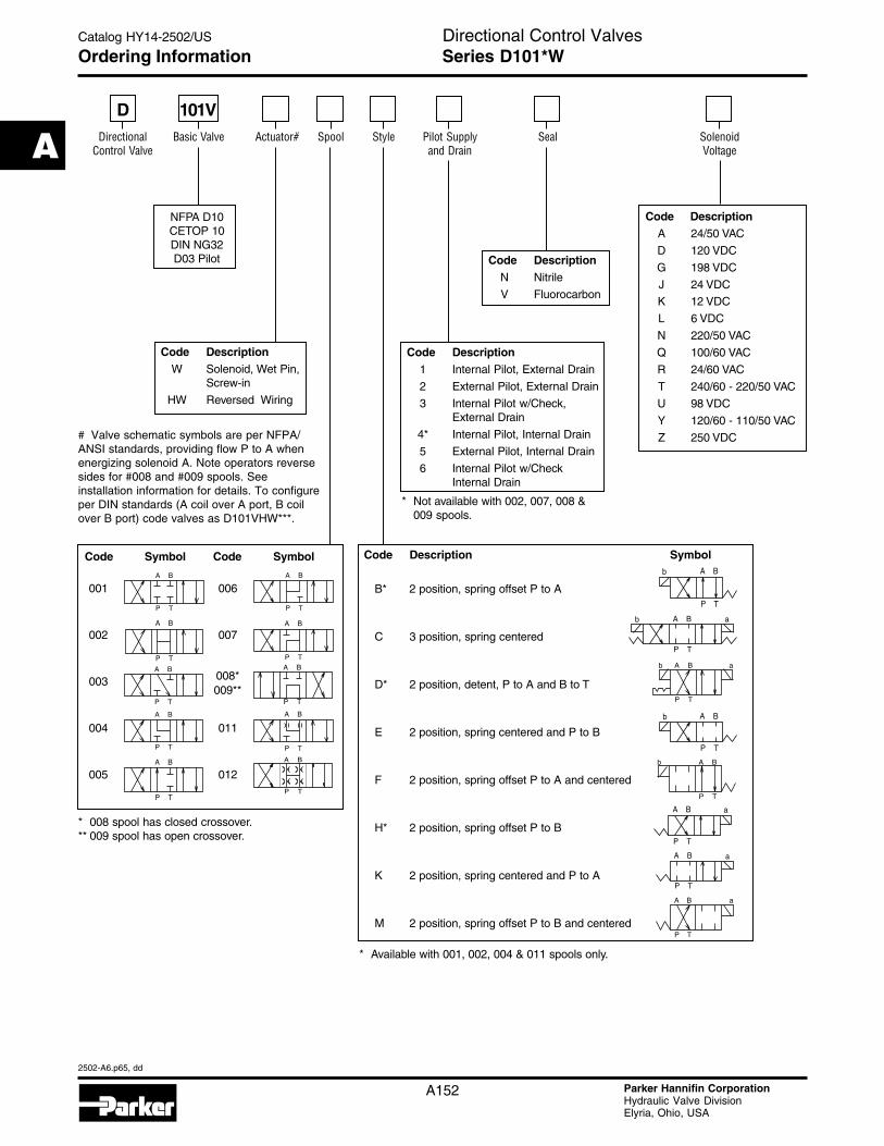
Ordering Information Series D101*W
Code DescriptionN Nitrile
V Fluorocarbon
Code DescriptionA 24/50 VAC
D 120 VDC
G 198 VDC
J 24 VDC
K 12 VDC
L 6 VDC
N 220/50 VAC
Q 100/60 VAC
R 24/60 VAC
T 240/60 - 220/50 VAC
U 98 VDC
Y 120/60 - 110/50 VAC
Z 250 VDC
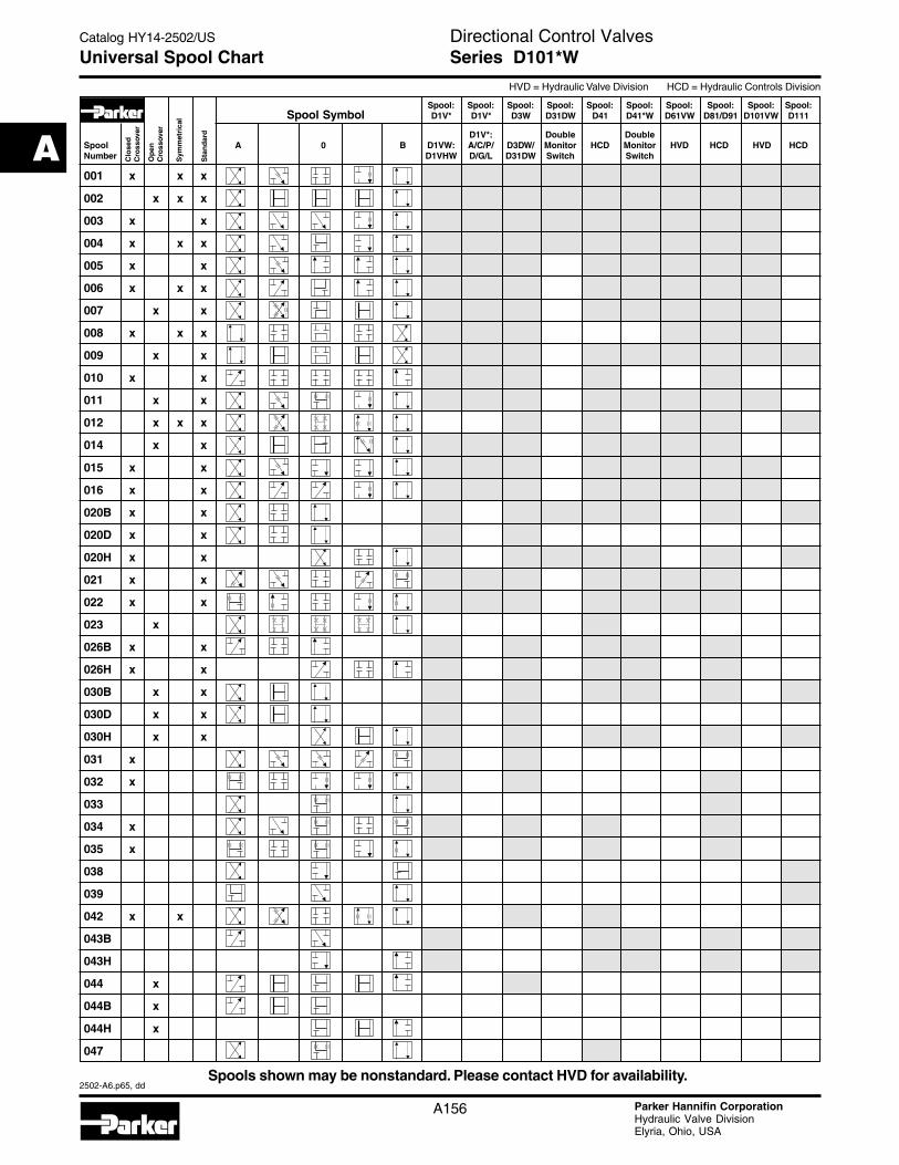
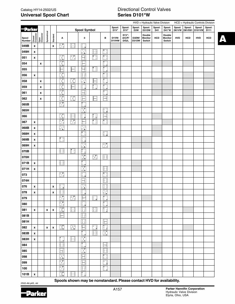
Code Description Symbol
B* 2 position, spring offset P to A
C 3 position, spring centered
D* 2 position, detent, P to A and B to T
E 2 position, spring centered and P to B
F 2 position, spring offset P to A and centered
H* 2 position, spring offset P to B
K 2 position, spring centered and P to A
M 2 position, spring offset P to B and centered
Code Symbol Code Symbol
001 006
002 007
003 008*009**
004 011
005 012
A B
P T
A B
P TA B
P T
A B
P T
A B
P T
A B
P TA B
P T
A B
P T
b A B
P T
A B
P T
b a
b A B
P T
A B
P T
b
b aA B
P T
aA B
P T
aA B
P T
A B
P T
a
A B
P T
DDirectional
Control ValveBasic Valve Actuator# Spool Style Seal Solenoid
Voltage
Code DescriptionW Solenoid, Wet Pin,
Screw-in
HW Reversed Wiring
Pilot Supplyand Drain
Code Description1 Internal Pilot, External Drain
2 External Pilot, External Drain
3 Internal Pilot w/Check,External Drain
4* Internal Pilot, Internal Drain
5 External Pilot, Internal Drain
6 Internal Pilot w/CheckInternal Drain
NFPA D10CETOP 10DIN NG32D03 Pilot
* 008 spool has closed crossover.** 009 spool has open crossover.
A B
P T
101V
# Valve schematic symbols are per NFPA/ANSI standards, providing flow P to A whenenergizing solenoid A. Note operators reversesides for #008 and #009 spools. Seeinstallation information for details. To configureper DIN standards (A coil over A port, B coilover B port) code valves as D101VHW***.
* Not available with 002, 007, 008 &009 spools.
* Available with 001, 002, 004 & 011 spools only.
Directional Control ValvesCatalog HY14-2502/US
2502-A6.p65, dd
A
A153 Parker Hannifin CorporationHydraulic Valve DivisionElyria, Ohio, USA
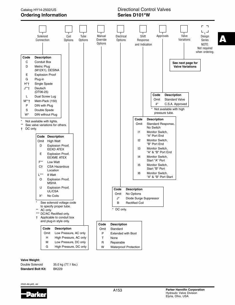
Ordering Information Series D101*W
Valve Weight:Double Solenoid 35.0 kg (77.1 lbs.)Standard Bolt Kit: BK229
Code DescriptionC Conduit Box
D Metric Plug(M12X1), DESINA
E Explosion Proof
G Plug-in
H*† Single Spade
J**† Deutsch(DT06-25)
L Dual Screw Lug
M**† Metri-Pack (150)
P DIN with Plug
S Double Spade
W* DIN without Plug
Code DescriptionOmit High Watt
D Explosion Proof,EEXD ATEX
E Explosion Proof,EEXME ATEX
F** Low Watt
C† CSA HazardousLocation
L*** 8 Watt
O Explosion Proof,MSHA
U Explosion Proof,UL/CSA
X* No Coils
SolenoidConnection
TubeOptions
Approvals DesignSeriesNOTE:
Not requiredwhen ordering.
ManualOverrideOptions
Code DescriptionOmit Standard
P Extended with Boot
T None
R Repairable
W Waterproof Protection
Code DescriptionOmit Low Pressure, AC only
H High Pressure, AC only
M Low Pressure, DC only
G High Pressure, DC only
CoilOptions
ElectricalOptions
Code DescriptionOmit No Options
J* Diode Surge Suppressor
B Rectified Coil
ShiftResponse
and Indication
* See solenoid voltage codeto specify proper tube.
** AC only.*** DC/AC Rectified only.† Applicable to conduit box
and plug-in style only.
* Not available with lights.** See valve variations for others.† DC only.
Code DescriptionOmit Standard Response,
No Switch
I1 Monitor Switch,"A" Port End
I2 Monitor Switch,"B" Port End
I3 Monitor Switch,"A" & "B" Port End
I4 Monitor Switch,Start "A" Port
I5 Monitor Switch,Start "B" Port
I6 Monitor Switch,"A" & "B" Port Start
Code DescriptionOmit Standard Valve
4* C.S.A. Approved
ValveVariations
See next page forValve Variations
* Not available with highpressure tube.
* DC only.
Directional Control ValvesCatalog HY14-2502/US
2502-A6.p65, dd
A
A154 Parker Hannifin CorporationHydraulic Valve DivisionElyria, Ohio, USA
Ordering Information Series D101*W
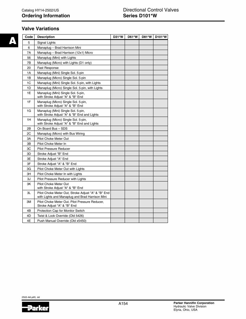
Valve Variations
Code Description D31*W D61*W D81*W D101*W
5 Signal Lights
6 Manaplug – Brad Harrison Mini
7A Manaplug – Brad Harrison (12x1) Micro
56 Manaplug (Mini) with Lights
7B Manaplug (Micro) with Lights (D1 only)
20 Fast Response
1A Manaplug (Mini) Single Sol. 5-pin
1B Manaplug (Micro) Single Sol. 5-pin
1C Manaplug (Mini) Single Sol. 5-pin, with Lights
1D Manaplug (Micro) Single Sol. 5-pin, with Lights
1E Manaplug (Mini) Single Sol. 5-pin,with Stroke Adjust "A" & "B" End
1F Manaplug (Micro) Single Sol. 5-pin,with Stroke Adjust "A" & "B" End
1G Manaplug (Mini) Single Sol. 5-pin,with Stroke Adjust "A" & "B" End and Lights
1H Manaplug (Micro) Single Sol. 5-pin,with Stroke Adjust "A" & "B" End and Lights
2B On Board Bus – SDS
2C Manaplug (Micro) with Bus Wiring
3A Pilot Choke Meter Out
3B Pilot Choke Meter In
3C Pilot Pressure Reducer
3D Stroke Adjust "B" End
3E Stroke Adjust "A" End
3F Stroke Adjust "A" & "B" End
3G Pilot Choke Meter Out with Lights
3H Pilot Choke Meter In with Lights
3J Pilot Pressure Reducer with Lights
3K Pilot Choke Meter Outwith Stroke Adjust "A" & "B" End
3L Pilot Choke Meter Out, Stroke Adjust "A" & "B" Endwith Lights and Manaplug and Brad Harrison Mini
3M Pilot Choke Meter Out, Pilot Pressure Reducer,Stroke Adjust "A" & "B" End
4B Protection Cap for Monitor Switch
4D Twist & Lock Override (Old 5426)
4E Push Manual Override (Old x5450)
Directional Control ValvesCatalog HY14-2502/US
2502-A6.p65, dd
A
A155 Parker Hannifin CorporationHydraulic Valve DivisionElyria, Ohio, USA
VISCOSITY CORRECTION FACTOR
Viscosity (SSU) 75 150 200 250 300 350 400% of ∆P (Approx.) 93 111 119 126 132 137 141Curves were generated using 100 SSU hydraulic oil. For any other viscosity,pressure drop will change per chart.
D101VW Pressure Drop Reference Chart -- Curve Number
A158 Parker Hannifin CorporationHydraulic Valve DivisionElyria, Ohio, USA
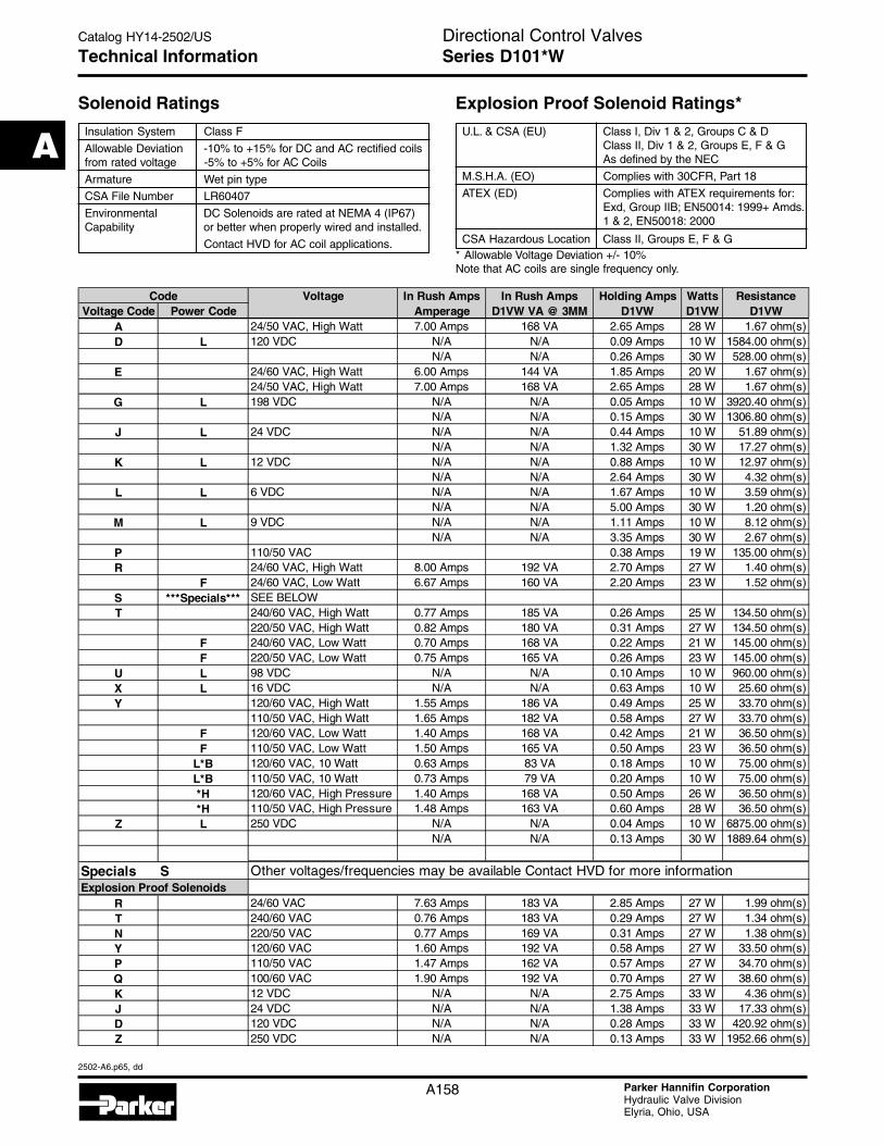
Solenoid Ratings
Insulation System Class F
Allowable Deviation -10% to +15% for DC and AC rectified coilsfrom rated voltage -5% to +5% for AC Coils
Armature Wet pin type
CSA File Number LR60407
Environmental DC Solenoids are rated at NEMA 4 (IP67)Capability or better when properly wired and installed.
Contact HVD for AC coil applications.
Explosion Proof Solenoid Ratings*
U.L. & CSA (EU) Class I, Div 1 & 2, Groups C & DClass II, Div 1 & 2, Groups E, F & GAs defined by the NEC
M.S.H.A. (EO) Complies with 30CFR, Part 18
ATEX (ED) Complies with ATEX requirements for:Exd, Group IIB; EN50014: 1999+ Amds.1 & 2, EN50018: 2000
CSA Hazardous Location Class II, Groups E, F & G* Allowable Voltage Deviation +/- 10%Note that AC coils are single frequency only.
Technical Information Series D101*W
Voltage In Rush Amps In Rush Amps Holding Amps Watts ResistanceVoltage Code Power Code Amperage D1VW VA @ 3MM D1VW D1VW D1VW
A 24/50 VAC, High Watt 7.00 Amps 168 VA 2.65 Amps 28 W 1.67 ohm(s)D L 120 VDC N/A N/A 0.09 Amps 10 W 1584.00 ohm(s)
N/A N/A 0.26 Amps 30 W 528.00 ohm(s)E 24/60 VAC, High Watt 6.00 Amps 144 VA 1.85 Amps 20 W 1.67 ohm(s)
24/50 VAC, High Watt 7.00 Amps 168 VA 2.65 Amps 28 W 1.67 ohm(s)G L 198 VDC N/A N/A 0.05 Amps 10 W 3920.40 ohm(s)
N/A N/A 0.15 Amps 30 W 1306.80 ohm(s)J L 24 VDC N/A N/A 0.44 Amps 10 W 51.89 ohm(s)
N/A N/A 1.32 Amps 30 W 17.27 ohm(s)K L 12 VDC N/A N/A 0.88 Amps 10 W 12.97 ohm(s)
N/A N/A 2.64 Amps 30 W 4.32 ohm(s)L L 6 VDC N/A N/A 1.67 Amps 10 W 3.59 ohm(s)
N/A N/A 5.00 Amps 30 W 1.20 ohm(s)M L 9 VDC N/A N/A 1.11 Amps 10 W 8.12 ohm(s)
N/A N/A 3.35 Amps 30 W 2.67 ohm(s)P 110/50 VAC 0.38 Amps 19 W 135.00 ohm(s)R 24/60 VAC, High Watt 8.00 Amps 192 VA 2.70 Amps 27 W 1.40 ohm(s)
F 24/60 VAC, Low Watt 6.67 Amps 160 VA 2.20 Amps 23 W 1.52 ohm(s)S ***Specials*** SEE BELOWT 240/60 VAC, High Watt 0.77 Amps 185 VA 0.26 Amps 25 W 134.50 ohm(s)
220/50 VAC, High Watt 0.82 Amps 180 VA 0.31 Amps 27 W 134.50 ohm(s)F 240/60 VAC, Low Watt 0.70 Amps 168 VA 0.22 Amps 21 W 145.00 ohm(s)F 220/50 VAC, Low Watt 0.75 Amps 165 VA 0.26 Amps 23 W 145.00 ohm(s)
U L 98 VDC N/A N/A 0.10 Amps 10 W 960.00 ohm(s)X L 16 VDC N/A N/A 0.63 Amps 10 W 25.60 ohm(s)Y 120/60 VAC, High Watt 1.55 Amps 186 VA 0.49 Amps 25 W 33.70 ohm(s)
110/50 VAC, High Watt 1.65 Amps 182 VA 0.58 Amps 27 W 33.70 ohm(s)F 120/60 VAC, Low Watt 1.40 Amps 168 VA 0.42 Amps 21 W 36.50 ohm(s)F 110/50 VAC, Low Watt 1.50 Amps 165 VA 0.50 Amps 23 W 36.50 ohm(s)
L*B 120/60 VAC, 10 Watt 0.63 Amps 83 VA 0.18 Amps 10 W 75.00 ohm(s)L*B 110/50 VAC, 10 Watt 0.73 Amps 79 VA 0.20 Amps 10 W 75.00 ohm(s)*H 120/60 VAC, High Pressure 1.40 Amps 168 VA 0.50 Amps 26 W 36.50 ohm(s)*H 110/50 VAC, High Pressure 1.48 Amps 163 VA 0.60 Amps 28 W 36.50 ohm(s)
Z L 250 VDC N/A N/A 0.04 Amps 10 W 6875.00 ohm(s)N/A N/A 0.13 Amps 30 W 1889.64 ohm(s)
Specials S Other voltages/frequencies may be available Contact HVD for more informationExplosion Proof Solenoids
R 24/60 VAC 7.63 Amps 183 VA 2.85 Amps 27 W 1.99 ohm(s)T 240/60 VAC 0.76 Amps 183 VA 0.29 Amps 27 W 1.34 ohm(s)N 220/50 VAC 0.77 Amps 169 VA 0.31 Amps 27 W 1.38 ohm(s)Y 120/60 VAC 1.60 Amps 192 VA 0.58 Amps 27 W 33.50 ohm(s)P 110/50 VAC 1.47 Amps 162 VA 0.57 Amps 27 W 34.70 ohm(s)Q 100/60 VAC 1.90 Amps 192 VA 0.70 Amps 27 W 38.60 ohm(s)K 12 VDC N/A N/A 2.75 Amps 33 W 4.36 ohm(s)J 24 VDC N/A N/A 1.38 Amps 33 W 17.33 ohm(s)D 120 VDC N/A N/A 0.28 Amps 33 W 420.92 ohm(s)Z 250 VDC N/A N/A 0.13 Amps 33 W 1952.66 ohm(s)
Code
Directional Control ValvesCatalog HY14-2502/US
2502-A6.p65, dd
A
A159 Parker Hannifin CorporationHydraulic Valve DivisionElyria, Ohio, USA
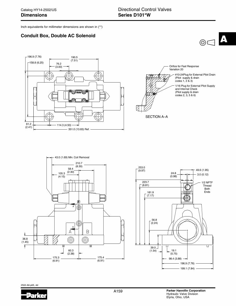
Dimensions
Inch equivalents for millimeter dimensions are shown in (**)
Series D101*W
Conduit Box, Double AC Solenoid
196.9 (7.76)
158.8 (6.25)
190.5(7.51)
76.2(3.00)
351.0 (13.83) Ref.
114.3 (4.50)61.2(2.41)
Orifice for Fast ResponseVariation 20
#10-24Plug for External Pilot Drain(Pilot supply & draincodes 1, 2 & 3)
1/16 Plug for External Pilot Supplyand Internal Check(Pilot supply & draincodes 2, 3, 5 & 6)
SECTION A–A
43.0 (1.69) Min. Coil Removal
210.7(8.30)
58.4(2.30)105.3
(4.15)
175.3(6.91)
175.4(6.91)
60.3(2.38)
36.8(1.45)
253.0(9.97)
24.8(0.98)
223.7(8.81)
181.9(7.17)
56.8(2.24)
39.0(1.54) 19.1
(0.75)
98.4 (3.88)
196.9 (7.76)
199.1 (7.84)
49.6 (1.95)
3.0 (0.12)
1/2 NPTFThreadBothEnds
Directional Control ValvesCatalog HY14-2502/US
2502-A6.p65, dd
A
A160 Parker Hannifin CorporationHydraulic Valve DivisionElyria, Ohio, USA
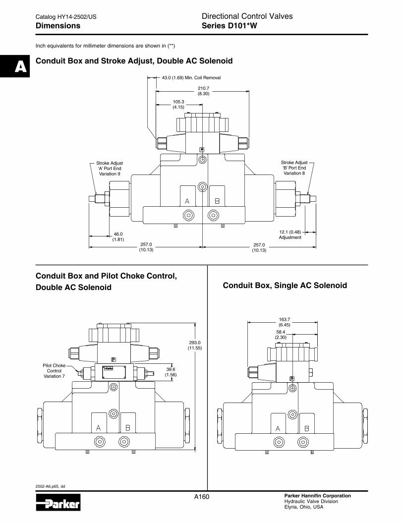
Series D101*W
Inch equivalents for millimeter dimensions are shown in (**)
Dimensions
Conduit Box and Stroke Adjust, Double AC Solenoid
Conduit Box and Pilot Choke Control,Double AC Solenoid Conduit Box, Single AC Solenoid
43.0 (1.69) Min. Coil Removal
210.7(8.30)
105.3(4.15)
Stroke Adjust‘A’ Port EndVariation 9
Stroke Adjust‘B’ Port EndVariation 8
257.0(10.13)
12.1 (0.48)Adjustment
257.0(10.13)
46.0(1.81)
293.0(11.55)
39.6(1.56)
Pilot ChokeControl
Variation 7
163.7(6.45)
58.4(2.30)
Directional Control ValvesCatalog HY14-2502/US
2502-A6.p65, dd
A
A161 Parker Hannifin CorporationHydraulic Valve DivisionElyria, Ohio, USA
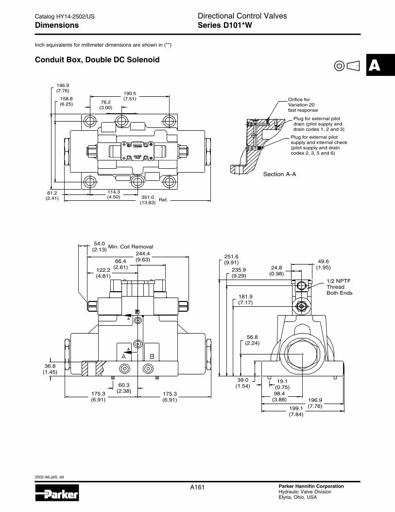
Series D101*W
Inch equivalents for millimeter dimensions are shown in (**)
Dimensions
Conduit Box, Double DC Solenoid
190.5(7.51)
196.9(7.76)
158.8(6.25)
61.2(2.41) 351.0
(13.83)Ref.
Section A-A
Orifice forVariation 20fast response
Plug for external pilotsupply and internal check(pilot supply and draincodes 2, 3, 5 and 6)
Plug for external pilotdrain (pilot supply anddrain codes 1, 2 and 3)
54.0(2.13)
122.2(4.81)
36.8(1.45)
175.3(6.91)
175.3(6.91)
39.0(1.54)
56.8(2.24)
181.9(7.17)
251.6(9.91)
235.9(9.29)
24.8(0.98)
49.6(1.95)
1/2 NPTFThreadBoth Ends
196.9(7.76)
98.4(3.88)
199.1(7.84)
19.1(0.75)60.3
(2.38)
66.4(2.61)
244.4(9.63)
Min. Coil Removal
114.3(4.50)
76.2(3.00)
Directional Control ValvesCatalog HY14-2502/US
2502-A6.p65, dd
A
A162 Parker Hannifin CorporationHydraulic Valve DivisionElyria, Ohio, USA
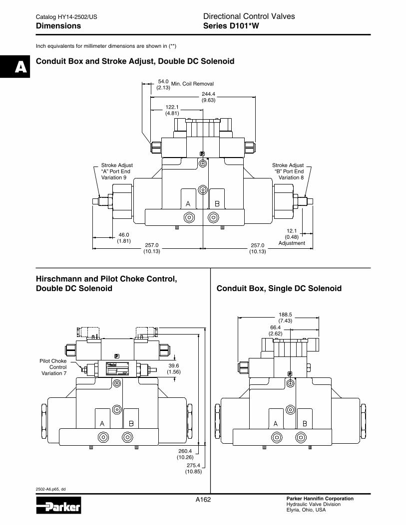
Series D101*W
Inch equivalents for millimeter dimensions are shown in (**)
Dimensions
Conduit Box and Stroke Adjust, Double DC Solenoid
Hirschmann and Pilot Choke Control,Double DC Solenoid Conduit Box, Single DC Solenoid