114
DOUD- 70857 Revision 2 May 2002 U.S. Department of Energy Idaho Operations Off ice INEEL CERCLA Disposal Facility Construction Quality Assurance Plan
DOUD- 70857 Revision 2 May 2002
U.S. Department of Energy Idaho Operations Off ice
INEEL CERCLA Disposal Facility Construction Quality Assurance Plan

DOWID-10851 Revision 2
INEEL CERCLA Disposal Facility Construction Quality Assurance Plan
May 2002
Prepared for the U.S. Department of Energy
Idaho Operations Office
ABSTRACT
This Construction Quality Assurance Plan describes the construction quality assurance responsibilities and procedures for work anticipated during Cell 1, Phase 2, and Cell 2 construction for the INEEL CERCLA Disposal Facility. This shall include construction of the liner, leachate collection piping, and operation layer for Cell 1, Cell 2, and the evaporation ponds. This Construction Quality Assurance Plan is prepared as a stand-alone document to be implemented by an independent, third-party Construction Quality Assurance certifying officer.
... 111


CONTENTS ... ABSTRACT ................................................................................................................................................ 111
ACRONYMS ...............................................................................................................................................xi
SECTION 1-GENERAL .......................................................................................................................... I- 1
1 . INTRODUCTION ........................................................................................................................... 1-1
1.1 Purpose .................................................................................................................................. 1-1
1.2 Scope ..................................................................................................................................... 1-2
1.3 Change Control Procedures ................................................................................................... 1-2
1.4 Regulatory Agencies ............................................................................................................. 1-2
2 . PROJECT ORGANIZATION ......................................................................................................... 1-4
2.1 Responsibility and Authority ................................................................................................. 1-4
2.1.1 Project Team ............................................................................................................... 1-4 2.1.2 Field Team .................................................................................................................. 1-6
2.2 Project Meetings .................................................................................................................... 1-8
2.2.1 Pre-Construction Meeting ........................................................................................... 1-8 2.2.2 Daily Meetings ............................................................................................................ 1-9 2.2.3 Bi-Weekly Progress Meetings .................................................................................... 1-9 2.2.4 Problem or Work Deficiency Meetings .................................................................... 1-10
2.3 Hold Points .......................................................................................................................... 1-10
3 . PERSONNEL QUALIFICATIONS AND TRAINING ................................................................ 1-11
3.1 CQA Certifying Officer ....................................................................................................... I- 11
3.2
3.3
3.4
CQA Monitor ...................................................................................................................... I- 11
Field Inspector ..................................................................................................................... I- 12
Soils Laboratory Technician ............................................................................................... 1-12
3.5
DEFINITIONS RELATING TO CONSTRUCTION QUALITY ASSURANCE ........................ 1-14
Geos ynthetic Laboratory ..................................................................................................... I- 12
4 .
4.1 Construction Quality Assurance and Construction Quality Control ................................... 1-14
4.2 Use of the Terms in This Plan ............................................................................................. 1-14
V

5 . REFEWNCES .............................................................................................................................. I- 15
5.1 Applicable Organizations .................................................................................................... I- 15
5.2 Applicable Standards ........................................................................................................... 1-15
6 . CONSTRUCTION ACTWRIES AND SUBMITTAL REQUREMENTS ................................ 1-16
6.1 Construction Activities ........................................................................................................ 1-16
6.2 Submittal Requirements ...................................................................................................... I- 17
SECTION 11-SOILS CONSTRUCTION QUALITY ASSURANCE .................................................... 11-1
1 . INTRODUCTION .......................................................................................................................... II- 1
2 . FILL PLACEMENT AND COMPACTION .................................................................................. 11-2
2.1
PREPARED SUBGRADE .............................................................................................................. 11-4
3.1 Layer Completion Certification ............................................................................................ 11-4
Construction Quality Assurance Evaluation ........................................................................ 11-2
3 .
4 . SOIL BENTONITE LINER AND TEST PAD .............................................................................. 11-5
4.1 Test Pad ................................................................................................................................ 11-5
4.1.1 Construction Quality Assurance Evaluation .............................................................. 11-5
4.2 Soil Bentonite Liner ............................................................................................................. 11-6
4.2.1 Construction Quality Assurance Evaluation .............................................................. 11-6 4.2.2 Layer Completion Certification ............................................................................... 11-10
5 . GRAVEL AND SAND ................................................................................................................. 11-11
5.1
5.2
5.3
Conformance Evaluation .................................................................................................... 11- 1 1
Placement and Compaction ................................................................................................ 11-1 1
Construction Quality Assurance Evaluation ...................................................................... 11-12
5.4 Layer Completion Certification .......................................................................................... 11-12
6 . OPERATIONS LAYER ............................................................................................................... 11-1 3
6.1 Conformance Evaluation .................................................................................................... II- 13
7 . SOIL SURVEYING ................................................................................................... J .................. 11-15
vi

SECTION 111-GEOSYNTHETIC CLAY LINER CONSTRUCTION QUALITY ASSURANCE ...... 111- 1
1 . GEOSYNTHETIC CLAY LINER MANUFACTURE AND DELIVERY ................................... 111-1
1 . 1 Labeling .............................................................................................................................. .I1 I. 1
1.2 Transportation and Handling .............................................................................................. .III . 1
1.3 Storage ................................................................................................................................ .I1 I. 1
1.4 . Inventory ............................................................................................................................. 111-1
1.5 Quality Assurance Conformance Testing ............................................................................ 111-3
2 . GEOSYNTHETIC CLAY LINER INSTALLATION ................................................................. .II I 5
2.1 Earthworks ........................................................................................................................... 111.5
2.1.1 Surface Preparation .................................................................................................. .II I 5 2.1.2 Anchor Trenches and Sumps ...................................................................................... 1-5
2.2 Geosynthetic Clay Liner Deployment ................................................................................. 111-6
2.2.1 Field Panel Identification ......................................................................................... x1-6 2.2.2 Field Panel Placement .............................................................................................. .I1 1-6 2.2.3 Field Panel Protection .............................................................................................. .I1 1-7
2.3 Defects and Repairs ............................................................................................................ .I1 1-7
2.3.1 Identification ............................................................................................................ x1-7 2.3.2 Repair Procedures ......................................................................................................I- 7
SECTION N-GEOMEMBRANE CONSTRUCTION QUALITY ASSURANCE ............................ IV- 1
1 . GEOMEMBRANE MATERIAL .................................................................................................. 1v-1
1.1 Labeling .............................................................................................................................. 1v-1
1.2 Transportation and Handling .............................................................................................. 1v-1
1.3 Storage ................................................................................................................................ 1v-1
1.4 Inventory ............................................................................................................................ 1v-1
1.5 Quality Assurance Conformance Testing ........................................................................... 1v-3
2 . GEOMEMBRANE INSTALLATION ......................................................................................... 1v-5
2.1 Earthworks .......................................................................................................................... 1v-5
2.1.1 Surface Preparation .................................................................................................. 1v-5 2.1.2 Anchor Trenches and Sumps ................................................................................... N-5
vii

Geomembrane Deployment ................................................................................................ IV-6
2.2.2 Field Panel Identification ......................................................................................... iv-6 2.2.1 Layout Drawing ....................................................................................................... iv-6
2.2.3 Field Panel Placement .............................................................................................. iv-6
Field Seaming ..................................................................................................................... 1v-7
2.3.1 Seam Layout ............................................................................................................ 1v-7 2.3.2 Seaming Equipment and Products ........................................................................... 1v-7
2.3.4 Weather Conditions for Seaming ............................................................................. 1v-7 2.3.5 Trial Seams .............................................................................................................. 1v-7
2.3.7 Destructive Seam Testing ........................................................................................ 1v-8
Defects and Repairs .......................................................................................................... 1v-1 1
2.3.3 Seam Preparation ..................................................................................................... 1v-7
2.3.6 Nondestructive Seam Continuity Testing ................................................................ 1v-8
2.4.1 Identification .......................................................................................................... N-11 2.4.2 Evaluation .............................................................................................................. 1v-11
2.4.4 Repair Procedures .................................................................................................. 1v-1 1 2.4.5 Testing of Repairs .................................................................................................. 1v-1 1
Appurtenances .................................................................................................................. 1v-11
2.4.3 Large Wrinkles ....................................................................................................... 1v-11
3 .
4 .
GEOMEMBRANE PANEL LAYOUT SURVEY ..................................................................... 1v-13
LAYER COMPLETION CERTIFICATION ............................................................................. 1v-14
SECTION V-GEOTEXTILE CONSTRUCTION QUALITY ASSURANCE ...................................... V- 1
GEOTEXTLE MATERIAL AND INSTALLATION ................................................................... V-1 1 .
1 .1
1.2
1.3
1.4
1.5
1.6
1.7
1.8
Labeling ................................................................................................................................ V.1
Transportation and Handling ................................................................................................ V-1
Storage .................................................................................................................................. V-1
Inventory .............................................................................................................................. V-1
Conformance Testing ........................................................................................................... V-3
Deployment .......................................................................................................................... V-4
Seams and Overlaps ............................................................................................................. V-4
Repair ................................................................................................................................... V-5
viii

SECTION VI-GEOCOMPOSITE CONSTRUCTION QUALITY ASSURANCE ............................. VI- 1
1 . GEOCOMPOSITE MATERIAL AND INSTALLATION .......................................................... vi-1
1.1 Labeling .............................................................................................................................. vi-1
1.2 Transportation and Handling .............................................................................................. vi-1
1.3 Storage ................................................................................................................................ v1-1
1.4 Inventory ............................................................................................................................ v1-1
1.5 Conformance Testing ......................................................................................................... v1-3
1.6 Deployment ........................................................................................................................ v1-3
1.7 Seams and Overlaps ........................................................................................................... v14
1.8 Repair ................................................................................................................................. v1-5
SECTION VII-POLYETHYLENE PIPE AND FITTINGS ................................................................ VII- 1
1 . PIPE AND FITTINGS ................................................................................................................. v11-1
1.1 Labeling ............................................................................................................................. v11-1
1.2 Transportation and Handling ............................................................................................. VII- 1
1.3 Storage ............................................................................................................................... v11-1
1.4 Inventory ........................................................................................................................... v11-1
1.5 Conformance Testing ........................................................................................................ v11-2
1.6 Handling and Laying ......................................................................................................... v11-2
1.7 Joints and Connections ...................................................................................................... v11-2
1.8 Surveying ........................................................................................................................... v11-3
SECTION VIII-CONSTRUCTION QUALITY ASSURANCE DOCUMENTATION ......... : .......... VIII -1
1 . DOCUMENTATION ................................................................................................................. VIII-1
1.1
1.2
1.3
1.4
Daily Reports .................................................................................................................... VIII- 1
Inspection Data Sheets ..................................................................................................... VIII-2
Record Drawing Maintenance .......................................................................................... VIII-3
Non Conformance Reporting ........................................................................................... VIII-3
ix

1.5 Construction Interface Document ..................................................................................... VIII-3
1.6 Progress Reports ............................................................................................................... VIII-4
1.7 Final Documentation ........................................................................................................ VIII-4
1.8 Storage of Records ........................................................................................................... V~~I-5
SECTION E-REFERENCES .............................................................................................................. IX- 1
Appendix A-Forms
TABLES
1.1 . Submittals required .......................................................................................................................... I- 18
11-1 . Minimum frequency of testing for CQA evaluation of earthfill ................................................... 11-16
11-2 .
11-3 .
I 1 4 Minimum frequency of testing for CQA evaluation of SBL ......................................................... 11-17
11-5 . Maximum percentage of failed tests for CQA evaluation of soil bentonite liner .......................... 11-18
11-6 . Minimum frequency of testing for CQA evaluation of gravel and sand ....................................... 11-19
11-7 . Minimum frequency of testing for CQA evaluation of operations layer ...................................... 11-19
11-23 . Minimum frequency of testing for CQA evaluation of prepared subgrade ................................... 11-19
Minimum frequency of testing for CQA evaluation of structural fill and base soil ...................... 11-16
Test pad testing methods and minimum frequency ....................................................................... 11- 16
X

A R A R S
ASTM
BBWI
CERCLA
CID
CQA
CQC
DOE
DOE-ID
EDF
EPA
FFNCO
GCL
GRI
HSO
HWMA
ICDF
INEEL
INTEC
LCRS
LDRS
MCP
NCR
OSHA
PCB
ACRONYMS
applicable or relevant and appropriate requirements
American Society for Testing and Materials
Bechtel BWXT Idaho, LLC
Comprehensive Environmental Response, Compensation, and Liability Act
Construction Interface Document
construction quality assurance
construction quality control
Department of Energy
Department of Energy Idaho Operations Office
engineering design file
Environmental Protection Agency
Federal Facilities AgreemenVConsent Order
geosynthetic clay liner
Geosynthetic Research Institute
health and safety officer
Hazardous Waste Management Act
INEEL CERCLA Disposal Facility
Idaho National Engineering and Environmental Laboratory
Idaho Nuclear Technology and Engineering Center
leachate collection recovery system
leak detection recovery system
Management Control Procedures
Non Conformance Report
Occupational Safety and Health Administration
polychlorinated biphenyl
xi
PM
PRD
QA
QC
RAO
RCRA
RDICWP
RG
SBL
SLDRS
STR
TSCA
UCL
VDS
WAG
project manager
Performance Requirements Document
quality assurance
quality control
remedial action objective
Resource Conservation and Recovery Act
remedial desigdconstruction work plan
remedial guideline
soil bentonite liner
secondary leachate detection recovery system
subcontract technical representative
Toxic Substances Control Act
upper control limit
vendor data submittals
waste area group
xii

SECTION I-GENERAL
INEEL CERCLA Disposal Facility Construction Quality Assurance Plan
Section I-General 1. INTRODUCTION
The U.S. Department of Energy (DOE) has tasked Bechtel BWXT Idaho, LLC (BBWI) to construct a Comprehensive Environmental Response, Compensation, and Liability Act (CERCLA) disposal facility and evaporation ponds at the Idaho National Engineering and Environmental Laboratory (INEEL) near Idaho Falls, Idaho. Disposal of remediation waste, primarily contaminated soil, into the INEEL CERCLA Disposal Facility (ICDF) is scheduled to begin in 2003. This Construction Quality Assurance (CQA) Plan describes the quality assurance (QA) activities required for constructing the lining system, operation layer, and leachate collection piping of the ICDF landfill and evaporation ponds.
1.1 Purpose
During construction, QA activities shall be required to ensure the following:
0 Construction of the liner system, leachate collection piping, and operation layer are performed in accordance with the approved Construction Drawings. Technical Specifications (SPC-1475), and the INEEL CERCLA Disposal Facility Remedial DesignlConstruction Work Plan (RD/CWP) (DOE-11) 2002).
0 Borrow and disturbed areas are restored in accordance with the Technical Specifications.
0 Requirements of regulatory agencies related to documentation are satisfied.
0 Construction of the ICDF landfill and evaporation ponds can be certified.
This CQA Plan has been prepared to describe the activities that shall be performed during construction of the lining system, leachate collection system, and operation layer of Cell 1, Cell 2, and the evaporation ponds. Procedures invoked by this CQA Plan are intended to identify problems that may occur during construction and to document that these problems are corrected before accepting the construction.
This CQA Plan is intended to satisfy the regulatory requirements and guidance established in 40 CFR 264.19 and EPA's Technical Guidance Document Quality Assurance and Quality Control for Waste Containment Facilities (EPA 1993).
This CQA Plan is intended to be implemented by an independent, third-party CQA certifying officer familiar with EPA' s Technical Guidance Document Quality Assurance and Quality Control for Waste Containment Facilities and this CQA Plan. The CQA certifying officer will be supported by the number of CQA representatives necessary to implement the requirements in this CQA Plan and document the work.
I- 1

SECTION I-GENERAL
1.2 Scope
This CQA Plan establishes general administrative and documentation procedures that shall be applicable for selected activities of construction. With respect to responsibilities, personnel qualifications, and specific inspection and testing activities, this CQA Plan addresses only those activities associated with the soils, geosynthetics, and related liner and leachate collection system piping components for the ICDF landfill and evaporation ponds. Specific procedures relating to these CQA activities that are not addressed in this plan shall be performed in accordance with manufacturers’ recommendations or as directed by BBWI. The CQA Plan is divided into sections to provide quick access to CQA requirements for individual liner components. The sections are listed below:
Section I: General
Section 11: Soils CQA
Section 111: Geosynthetic Clay Liner CQA
Section IV: Geomembrane CQA
Section V: Geotextile CQA
Section VI: Geocomposite CQA
Section VIl: Polyethylene Pipe and Fittings
Section VIII: CQA Documentation.
1.3 Change Control Procedures
The CQA Plan and all implementing procedures are subject to the Construction Interface Document (CID) change control procedures described in Section VIII of this CQA Plan.
1.4 Regulatory Agencies
The ICDF Complex does not require a permit. It will be an engineered facility meeting the applicable or relevant and appropriate requirements (ARARs), the remedial action objectives (RAOs), and the remedial guidelines (RGs) documented in the Idaho Nuclear Technology and Engineering Center (INTEC), Waste Area Group (WAG) 3, Operable Unit 3-13 Record of Decision (ROD) (DOE-ID 1999); DOE Order 435.1, “Radioactive Waste Management;” Resource Conservation and Recovery Act (RCRA) Subtitle C: Idaho Hazardous Waste Management Act (HWMA); and Toxic Substances Control Act (TSCA) polychlorinated biphenyl (PCB) landfill design and construction requirements. The complex’s primary purpose is to provide a disposal facility for CERCLA-generated waste at INEEL to satisfy the requirements of the ROD. This CQA Plan is specifically designed to support this and regulatory requirements.
The regulatory agencies are responsible for oversight and implementing the responsibilities identified in the Federal Facilities Agreemendconsent Order (FFNCO) (DOE 1991). As provided in the Agreement, each Party to the Agreement is represented by a project manager. The project manager shall:
1-2

SECTION I-GENERAL
Manage INEEL remedial activities including the ICDF construction for their respective agencies pursuant to the Agreement and Action Plan
0 Serve as primary contacts and coordinators for their respective agencies for purposes of implementing the Agreement and Action Plan
0 Prioritize work for their respective agencies
0 Coordinate activities of WAG 3 project managers (PM), who are identified by the PMs, as necessary.
1-3

SECTION I-GENERAL
2. PROJECT ORGANIZATION
This section describes the project organization for the Phase 2 ICDF construction. The following subsections address the organizations involved in the construction, their respective roles in construction activities, and the methods of interactions between organizations.
2.1 Responsibility and Authority
The QA organization chart for the ICDF construction is shown in Figure 2-1. The project organization is divided into two main groups consisting of the project team and field team. The project team consists mainly of management and will be on-site during the ICDF construction periodically to monitor progress, meetings, dispute resolutions, and as needed to ensure that the work is implemented in accordance with the Construction Drawings, Technical Specifications, the RDICWP, and agreements made with the regulatory agencies. The field team will consist of the key personnel on-site during construction. The organization is based on a line and staff concept. Solid lines on the organization chart represent project responsibilities such as scope, cost, and schedule. The dashed lines represent the functional responsibilities of staff for QA, design, and health and safety. The responsibilities and reporting requirements for each project team member are described in the following sections.
2.1.1 Project Team
2.1.1.1 Department of Energy Idaho Operations Office (DOE-ID) PM. The DOE-ID project manager (PM) is the owner’s representative and is responsible for project funding and implementing the responsibilities identified in the FFNCO. The DOE-ID PM will keep the regulatory agencies informed of ICDF construction activities and progress.
2.1.1.2 WAG Manager. The WAG 3 PM is responsible for all WAG 3 activities that include the ICDF construction. The WAG 3 PM serves as the primary contact and coordinator for activities performed at WAG 3 for purposes of implementing the Agreement and Action Plan and interfaces with the INTEC site area director.
2.1.1.3 operation of the INTEC facility. The WAG 3 PM will keep the INTEC site area director informed of ICDF construction activities from an upper-level management perspective.
INTEC Site Area Director. The INTEC site area director is responsible for the overall
2.1.1.4 INTEC Tenant and Support Operations Manager. The INTEC tenant and support operations manager reports directly to the INTEC site area director. The ICDF project manager (ICDF PM) will interface with the INTEC tenant and support operations manager to ensure that ICDF activities are smoothly and safely integrated with ongoing INTEC activities and visa-versa.
2.1.1.5 interfaces with the INTEC tenant and support operations manager and WAG 3 project engineer. The ICDF PM will direct the activities of the ICDF project and field team staff including the WAG 3 quality engineer (for ICDF activities), procurement agent, ICDF project engineer, ICDF health and safety officer (HSO), and subcontract technical representative. Additionally, the ICDF PM functions as the point of contact for the ICDF design and construction subcontractor. Functionally, the ICDF PM reviews and approves quality assurance reports submitted by the ICDF CQA certifying officer.
ICDF PM. The ICDF PM will have overall responsibility for the ICDF construction and
1-4

i i;L m 5-
T
E
= I I-
a, u. .-
I
I
1-5

SECTION I-GENERAL
2.1.1.6 WAG 3 Project Engineer. The WAG 3 project engineer is responsible for providing technical support to the WAG 3 project team. The WAG 3 project engineer is supported by the ICDF project engineer for reviewing andor preparing technical documents related to engineering design and analyses. The WAG 3 project engineer reports to the WAG 3 PM.
2.1.1.7 WAG 3 Quality Engineer. The WAG 3 quality engineer has overall responsibility for the quality control (QC) and QA of remedial activities performed at WAG 3. The WAG 3 quality engineer is responsible for the construction quality engineer and field inspection team in the field. The WAG 3 quality engineer reports quality issues related to the ICDF construction directly to the ICDF PM.
2.7.1.8 accounting, and contract administration activities including approval of contract modifications for the construction subcontractor. The CQA certifying officer contractually reports to the procurement agent. The procurement agent reports to the ICDF PM on ICDF-related procurement activities.
Procurement Agent- The procurement agent is responsible for all purchasing, payables,
2.1.1.9 subcontractor is the design engineer of record and construction subcontractor. Functionally, the ICDF design and construction subcontractor prepares the Construction Drawings, specifications, operation and maintenance (O&M) plans, design studies, construction subcontractor supplier quality control plan, and this QA plan, which are reviewed and approved by the ICDF project engineer and ICDF PM. The ICDF design and construction subcontractor is then responsible for implementing the approved design by providing the necessary labor, equipment, materials, and all other resources necessary to construct the ICDF.
lCDF Design and Construction Subcontractor. The ICDF design and construction
2.1.1.10 lCDF Project Engineer. The ICDF project engineer is responsible for reviewing and/or preparing technical documents related to the ICDF design and construction. The ICDF project engineer reports to the ICDF PM and supports the WAG 3 project engineer.
2.1.1.11 and safety for the ICDF project. The ICDF HSO reports to the ICDF PM and is supported by the design and construction subcontractor’s safety and health officer in the field.
lCDF Health and Safety Officer. The ICDF HSO has overall responsibility for health
Note that when the above individuals are designated to perfom specific functions described in this CQA Plan, the reference to these individuals includes their designee or an alternate who can function on their behalf.
2.1.2 Field Team
2.1.2.1 Subcontract Technical Representative (STR)/construction coordinator oversees the ICDF construction activities in the field and is the on-site representative for the ICDF PM.
Subcontract Technical RepresentativdConstruction Coordinator. The
2.1.2.2 Construction Manager and Site Superintendent. The construction manager and superintendent represent the ICDF design and construction subcontractor and will be responsible for implementing the ICDF construction activities. The construction manager will have overall responsibility for all construction activities related to the ICDF. The superintendent will control the day-today construction tasks and will be the point of contact for the field personnel. The construction manager will visit the site periodically to ensure work is progressing smoothly and will be a substitute for the superintendent, if necessary. The construction manager and superintendent will be supported by the internal QC engineer and safety and health officer and will report to the STIUconstruction coordinator and the ICDF design and construction subcontractor’s project team.
1-6

SECTION I-GENEXAL
2.7.2.3 companies retained by the ICDF design and construction subcontractor to perform specific work activities at the ICDF such as earth moving, geosynthetic lining installation, piping, and fence installation. The construction subcontractors will report directly to the superintendent.
2.1.2.4 provide a construction QC engineer who will support the superintendent. The primary responsibility of the construction QC engineer will be to ensure that the work is performed in accordance with the Technical Specifications and Construction Drawings. Specific duties of the construction QC engineer will include activities such as preparing subconstruction submittals, field documentation, and interfacing with the CQA certifying officer.
Construction Subcontractors. Construction subcontractors will include specialty
Internal Construction Quality Control. The design and construction subcontractor will
2.7.2.5 Safety and Health Officer. The safety and health officer will support the superintendent in ensuring that all work activities are performed in a safe manner and in accordance with the project- specific health and safety plan. Functionally, the safety and health officer will provide health and safety information related to the ICDF construction to the project team’s ICDF HSO.
2.7.2.6 WAG 3 quality engineer and STWconstruction coordinator and is responsible for the field inspection team and quality assurance testing laboratory. The construction quality engineer will be responsible for providing the necessary number of qualified field inspection personnel and laboratory service for the CQA monitor and CQA certifying officer.
Construction Quality Engineer. The construction quality engineer reports to the
2- 1.2.7 a CQA representative, functionally supporting the CQA monitor and CQA certifying officer. The field inspector’s function will be to perform testing and observations in accordance with this CQA Plan under the direction of the CQA monitor and CQA certifying officer.
Field Inspector. The field inspector reports to the construction quality engineer and will be
2.1.2.8 Soils Laboratory Technicians. The laboratory technicians will report to the construction quality engineer and functionally will provide the QA testing required by this CQA Plan and as requested by the CQA monitor and CQA certifying officer.
2.7.2.9 be a CQA representative supported by the field inspection team and laboratory technician. The CQA monitor will ensure that all CQA tests are performed in accordance with this CQA Plan and accepted procedures.
CQA Monitor. The CQA monitor will report directly to the CQA certifying officer and will
2.7.2.10 CQA Certifying Officer. The CQA certifying officer will be an independent third-party and will have the overall responsibility of implementing this CQA Plan and shall directly supervise the CQA monitor, field inspection team, and laboratory technicians. Functionally, the CQA certifying officer will submit CQA reports to the ICDF PM. The CQA certifying officer will be a registered professional engineer in Idaho and will have the authority to certify that the ICDF is constructed in accordance with the approved plans and specifications and any approved changes. An independent third party is a company retained by the owner (or the owner’s representative) that is a separate entity from the company performing the construction. The CQA Certifying Officer also has the authority and responsibility to stop work and recommend remedial actions to the regulatory agencies, if the construction subcontractor is not adhering to the CQA Plan. Even though the CQA Certifying Officer reports to the STWconstruction manager and the ICDF PM, he or she has the independence and authority to stop work.
1-7

SECTION I-GENERAL
2.2 Project Meetings
This section includes a discussion of the various progress and status meetings that will be held throughout the ICDF construction. The purpose of the meetings is to discuss work progress, planning, and other issues related to construction. A portion of these meetings can be dedicated to CQA issues, as necessary, to provide an opportunity for the CQA team to express concerns regarding quality, to relay test results, and to ensure good communication between all organizations involved in the construction of the ICDF.
2.2.1 Pre-Construction Meeting
A preconstruction meeting will be scheduled prior to beginning major construction activities at the ICDF. At a minimum, the meeting will be attended by the ICDF PM, construction manager, STW construction coordinator, CQA monitor, and CQA certifying officer. A portion of the meeting will be dedicated to the discussion of QA issues. These CQA topics shall include, but not be limited to, the following:
’ *
0
Reviewing the responsibilities of each organization
Discussing the authority of agencies and project and field team members to order work stoppages
Reviewing lines of authority and communication for each organization
Providing each organization with all relevant CQA documents and supporting information
Familiarizing each organization with the CQA Plan and its role relative to the design criteria, plans, and specifications
Determining any changes to the CQA Plan that may be needed to document that the facility shall be constructed to meet or exceed the specified design requirements
Discussing the established procedures or protocol for observations and tests, including sampling strategies
Discussing the established procedures or protocol for handling construction deficiencies, repairs, and retesting, including “stop work” conditions
Reviewing methods for documenting and reporting inspection data
Reviewing methods €or distributing and storing documents and reports
Reviewing work area security and safety protocol
Reviewing the proposed project schedule
Discussing procedures for the location and protection of construction materials and for the prevention of damage of the materials from inclement weather or other adverse events
Conducting a site walk-around to review construction materials and inspect equipment storage lxations
1-8

SECTION I-GENERAL
0 Action items, assigned actionees, and minutes shall be recordsd and transmitted to the required distribution list and to meeting attendees.
2.2.2 Daily Meetings
The superintendent will conduct pre-job briefings at the work area. The participants shall include, at a minimum, the construction field personnel including lower tiered subcontractors and CQA representatives. The primary purpose of these meetings is to address the day’s planned activities and health and safety issues. Following the pre-job meeting, the CQA representatives will meet to discuss CQA activities planned for that day and interface needs with the construction personnel. The topics typically covered are listed below:
0 Review the previous day’s activities and accomplishments
0
0
Review the work location and activities for the day (plan of the day)
Discuss the construction subcontractor’s personnel and equipment assignments for the day
0 Address scheduling of resources for upcoming work
0 Review any new test data
Discuss any potential construction problems, including unexpected subsurface conditions that may jeopardize the ability to site the landfill cell or evaporation ponds according to Section 4.3.2.1
0 Discuss CQA-planned activities and interface needs
0 Discuss any health and safety issues.
This meeting shall be documented and the documentation shall be retained on file by the CQA monitor. The documentation shall be distributed to a list of individuals, to be determined at the Pre- Construction Meeting.
2.2.3 Bi-Weekly Progress Meetings
Bi-weekly meetings will be held at the site to discuss construction progress. At a minimum, the bi- weekly progress meetings shall be attended by the superintendent and/or construction manager, the STWconstruction coordinator, the ICDF PM or designated alternate, and the CQA certifying officer or designated alternate. The purpose of the meeting is to accomplish the following:
0 Review the previous week’s activities and accomplishments
0 Review claims, change orders, delays, and similar items
Review planned activities for the upcoming week
Finalize resolution of problems from the previous week
0 Discuss the potential problems with the work planned for the upcoming week.
1-9
SECTION I-GENERAL
Minutes will be recorded by a party identified by the STWconstruction coordinator and transmitted to the required distribution list and meeting attendees.
2.2.4 Problem or Work Deficiency Meetings
Meetings shall be convened as necessary to address CIDs, inspection deficiencies, and non- conformances. Deficiencies observed during construction by the CQA representatives shall be brought to the attention of the superintendent and CQA certifying officer immediately. These deficiencies will be tracked in the CQA representative’s field log book until resolution and included in the daily summary report. These documents shall include the description of the deficiency and actions taken or to be taken to resolve.
2.3 Hold Points
Mandatory hold points shall be established for certain key activities. At these points, the ICDF design and construction subcontractor shall cease work on the affected activity until it has been reviewed by the CQA monitor. Typical hold points would be between construction of liner system components and final operations layer placement. The schedule for hold points shall be determined when the ICDF design and construction subcontractor develops the construction schedule for the project.
I- 10

SECTION I-GENERAL
3. PERSONNEL QUALIFICATIONS AND TRAINING
This section describes the qualifications and training required for CQA personnel. All documentation relating to qualifications shall be maintained with the project CQA records.
3.1 CQA Certifying Officer
The CQA certifying officer shall be employed by an independent third party and have landfill construction certification experience. The CQA certifying officer shall, at a minimum, be a registered civil professional engineer in good standing in the State of Idaho, possess a bachelor’s degree in civil or construction engineering, geotechnical engineering, engineering geology, or a closely related discipline, and shall have sufficient practical, technical, and managerial experience to successfully direct the CQA activities discussed in this CQA Plan. The CQA certifying officer’s qualifications shall be documented by training records and professional resume showing significant field experience in landfill construction and low permeability clay liner construction, having directed CQA activities at a minimum of five landfill construction projects or a minimum of 300 acres of combined landfill area certifying experience. Qualification documentation shall be reviewed by the ICDF PM and WAG 3 project engineer. If acceptable, a project certification form shall be completed and retained in the project QA records. Certifications shall be valid for a period of one year, after which they must be renewed.
The CQA certifying officer shall receive formal training in the requirements of the BBWI quality program, including but not limited to, documentation, receiving inspection, equipment calibration, design control, and personnel training. The CQA certifying officer shall also have completed any DOE, BBWI, or other training required by BBWI’s project health and safety plan as well as activity-specific health and safety plans.
3.2 CQA Monitor
At a minimum, a CQA monitor shall have a high school diploma and at least five years of construction-related experience, including at least three years of experience conducting CQA monitoring for earthwork construction including a minimum of three landfill construction projects or a minimum of 50 acres of combined landfill area experience, or a bachelor of science degree from a four-year college or university, and at least two years of experience conducting CQA monitoring for earthworks construction including a minimum of three landfill construction projects. The CQA monitor must be capable of performing work with little or no daily supervision and shall be certified by a program approved by the CQA certifying officer. The CQA monitor shall be familiar with EPA’s Technical Guidance Document Quality Assurance and Quality Control for Waste Containment Facilities (EPA 1993).
Qualifications of the CQA monitor shall be documented by training records, and professional resumes and shall be reviewed by the ICDF PM and CQA certifying officer, and, if acceptable, shall be certified in the same manner noted in Section 3.1 above. Certifications shall be valid for a period of one year, after which they must be renewed.
The CQA monitor shall receive formal training in the requirements of the BBWI quality program, including but not limited to, documentation, receiving inspection, equipment calibration, design control, and personnel training. The CQA monitor shall also have completed any DOE, BBWI, or other training required by BBWI’s project health and safety plan as well as activity-specific health and safety plans.
1-1 I

SECTION I-GENERAL,
3.3 Field Inspector
At a minimum, a field inspector shall have a high school diploma and at least two yeaii of construction-related experience, including at least one year of experience conducting CQA monitoring for earthwork construction, or a bachelor of science degree from a four-year college or university and at least six months of experience conducting field inspection for earthworks construction. The field inspector must be capable of routine engineering technician work under general daily supervision and shall be certified by a program approved by the CQA certifying officer. The field inspector shall be familiar with EPA' s Technical Guidance Document Quality Assurance and Quality Control for Waste Containment Facilities (EPA 1993).
Qualifications of a field inspector shall be documented by training records and professional resumes and shall be reviewed by the ICDF PM and CQA certifying officer, and, if acceptable, shall be certified in the same manner noted in Section 3.1 above. Certifications shall be valid for a period of one year, after which they must be renewed.
The field inspector shall receive formal training in the requirements of the BB WI quality program, including, but not limited to, documentation, receiving inspection, equipment calibration, design control, and personnel training. The field inspector shall also have completed any DOE, BBWI, or other training required by BBWI's project health and safety plan as well as activity-specific health and safety plans.
3.4 Soils Laboratory Technician
At a minimum, a laboratory technician shall have a high school diploma and at least five years of construction materials laboratory testing related experience, including at least three years of experience performing geotechnical laboratory tests for earthwork construction, including compacted low permeability clay, or a bachelor of science degree from a four-year college or university and at least two years of experience performing geotechnical laboratory tests for earthwork construction, including low permeability clay. The laboratory technician must be capable of routine laboratory technician work under general daily supervision and shall be certified by a program approved by the CQA certifying officer.
Qualifications of a laboratory technician, including training records and professional resumes, shall be reviewed by the ICDF PM and CQA certifying officer, and, if acceptable, shall be certified in the same manner noted in Section 3.1 above. Certifications shall be valid for a period of one year, after which they must be renewed.
A laboratory technician shall receive formal training in the requirements of the BBWI quality program, including, but not limited to, documentation, receiving inspection, equipment calibration, design control, and personnel training. The laboratory technician shall also have completed any DOE, BBWI, or other training required by BBWI's project health and safety plan, as well as activity-specific health and safety plans.
3.5 Geosynthetic Laboratory
The geosynthetic laboratory will be selected by the CQA certifying officer and will provide the geosynthetic QA conformance testing required by this CQA Plan, as requested by the CQA monitor andor CQA certifying officer. The geosynthetics CQA laboratory is a third-party, independent testing laboratory, unaffiliated with the design engineer, materials supplier or manufacturer, or construction contractor or subcontractors. The geosynthetics CQA laboratory will have at least five years of experience in testing geosynthetics and other relevant liner system components, and will be familiar with American
1-12

SECTION I-GENERAL
Society for Testing and Materials (ASTM) and other applicable test standards. The geosynthetics CQA laboratory will be accredited by the Geosynthetics Accreditation Institute.
1-13

SECTION I-GENERAL
4. DEFINITIONS RELATING TO CONSTRUCTION QUALITY ASSURANCE
4.1 Construction Quality Assurance and Construction Quality Control
Construction Quality Assurance-A planned and systematic pattern of the means and actions designed to provide adequate confidence that items or services meet contractual and regulatory requirements, and will perform satisfactorily in service.
Construction Quality Control (CQC)-Those actions that provide a means to measure and control the characteristics of an item or service to meet contractual and regulatory requirements.
4.2 Use of the Terms in This Plan
The definitions used in the context of this CQA Plan are provided below:
0 CQA refers to means and actions employed by the CQA representatives to assure conformity of liner system preparation, production, and installation with this CQA Plan, the Technical Specifications, and the Construction Drawings. CQA is provided by a party independent from the product manufacturer and construction subcontractor.
CQC refers to those actions taken by manufacturers, suppliers, or construction subcontractors, including their designated representatives, to ensure that the materials and the workmanship meet the requircments of the Technical Specifications and the Construction Drawings. In the case of soils, and within this CQA Plan, CQC is typically made a part of the CQA requirements and is provided by the CQA representatives. In the case of geosynthetic and other non-soil components, CQC is provided by the manufacturers and construction subcontractor’s installers of the various geosynthetics.
I- 14

SECTION I-GENERAL
5. REFERENCES
5.1 Applicable Organizations
Organizations whose standards are referenced in the CQA Plan are listed below:
0 ASTM-American Society for Testing and Materials
0 DOE-Department of Energy
0 GRI-Geosynthetic Research Institute
0 OSHA-Occupational Safety and Health Administration
0 EPA-U.S. Environmental Protection Agency.
5.2 Applicable Standards
Any reference to standards of any society, institute, association, or governmental agency will pertain to the edition in effect as of the date of this CQA Plan, unless stated otherwise.
Specific test standards for tests cited in the CQA Plan are provided in the Technical Specifications. These standards may be modified due to technological advances since compilation of the Technical Specifications. All such modifications are to be approved in accordance with the construction interface document procedures described in Section VIII.
1-15

SECTION I-GENERAL
6. CONSTRUCTION ACTIVITIES AND SUBMITTAL REQUIREMENTS
6.1 Construction Activities
This section describes the construction activities and submittal requirements that shall be performed by the construction subcontractor during the ICDF construction. This CQA Plan only addresses selected activities of the Phase 2 portion of Cell 1 construction, which is planned for the 2002 summer construction season. It is also applicable for the same activities associated with Cell 2 construction to be completed at a later date. Phase 1 construction was completed under a separate CQA Plan at the end of the 2001 summer construction season that consisted of the site preparation activities listed below.
0
0
0
Approving work order
Mobilizing construction equipment and personnel
Submitting of vendor data submittals (VDS)
Installing sediment and erosion control
Constructing haul roads
Mobilizing equipment for test pad
Clearing, grubbing, and stripping
Preparing stockpile area subgrade
Excavating ICDF landfill Cell 1
Constructing test pad
Constructing evaporation ponds pad embankments
Restoring site
Demobilizing.
In general, Phase 2 construction activities will consist of installing the secondary leachate detection -
recovery system recovery system and evaporation
(SLDRS), liner system, the leak detection recovery system (LDRS), the leak collection (LCRS), and operations layer and necessary equipment to complete the landfill Cell 1 ponds for waste acceptance. Phase 2 of the Cell 1 construction will consist of the
following activities:
Remobilizing construction equipment and personnel
VDSs
Installing sediment and erosion control
1-16

SECTION I - G E N E W
Preparing soil bentonite material
Fine grading of Cell 1 subgrade and sump construction
Placing the geosynthetics for the tertiary liner
Constructing the secondary leak detection recovery system
Constructing the soil bentonite liner (SBL)
Placing the geosynthetics for the secondary liner
Constructing the primary leak detection recovery system
Placing the geosynthetics for the primary liner
Constructing the leachate collection recovery system
Constructing the liner system for the evaporation ponds
Constructing the operations layer
Site restoration
Demobilization.
Similar activities will be performed during Cell 2 construction. This CQA Plan may be used for these same activities where appiopriate during Cell 2 construction.
Prior to the start of construction activities, the CQA representatives shall review and become familiar with the RD/CWP, including all Construction Drawings and Technical Specifications. The CQA certifying officer should also be familiar with the most recent construction schedule so that adequate resources (ie., laboratory, field testing equipment, staff, and CQA forms) including contingencies (e.g., backup equipment, alternate laboratory, and alternate CQA staff) for CQA activities will be commensurate with the anticipated construction productivity and work schedule. All necessary measures should be taken to avoid delaying construction activities and the completion of the ICDF.
6.2 Submittal Requirements
The construction subcontractor will provide the submittals required by this section to the ICDF PM in accordance with INEEL Program Requirements Document (PRD) 5003, Vendor Data Control. Submittals will be provided far enough in advance of scheduled installation dates to provide time for reviews (allow 2 1 working days), possible revisions and resubmittals, and placing orders and securing delivery. Prior to submittal of vendor data, the construction subcontractor shall initiate INEEL’s project- specific Form 432.37, Subcontractor/Supplier Vendor Data Submittal Log, or approved equivalent, to identify, track, and status all required vendor data. The ICDF PM will respond to each required submittal with one of the following disposition codes:
0 “A”-Related work may proceed
1-17

SECTION I-GENERAL
0 “B”-Related work may proceed only after comments have been incorporated or otherwise reconciled
0 “C”-Related work shall not proceed and a revised vendor data transmittal and disposition form s ubmi tied
0 “D’-No further action is required except for information only copies that m y receive comments by the contractor and the construction subcontractor shall respond to these comments within 20 calendar days.
The submittals presented in Table 1-1 will be required.
Table 1-1. Submittals required.
Submittal Description Requirement Proposed panel layout drawings
Subgrade surface acceptance
GCL material certifications and test data
Proposed layout drawings for each layer of geosynthetic clay liner (GCL) and geomembrane material. Geomembrane layout shall show panel configuration, general dimensions, and seam locations. GCL layout shall be more general showing panel orientation.
Certification in writing that the surface on which the GCL or geomembrane will be installed is acceptable to the installer. A certificate of acceptance will be provided by the construction subcontractor to the CQA representative, who will then verify to the CQA certifying offtcer that the deployment surface has been accepted immediately prior to commencement of GCL or geomembrane installation in the area under consideration.
Provide manufacturers’ QC test data for GCL material to be installed, including:
Bentonite - suppliers’ name and location, brand name, lot number, dated quality control information from supplier, manufacturers’ test data verifying that bentonite meets manufacturers’ specifications.
Geotextile - dated quality control information from supplier.
GCL - manufacturers’ specification measured using appropriate test methods, written guarantee that GCL conforms to the Technical Specification requirements, and QA certificates for each 100,OOO square feet of GCL material including roll numbers, test methods, and test results verifying compliance with the Technical Specification requirements for GCL.
Submitted by the construction subcontractor and approved by the CQA certifying officer prior to the installation of the respective GCL or geomembrane liner.
Certificate signed by the installer and construction subcontractor prior to installation of GCL or geomembrane over the subgrade.
Submitted by the construction subcontractor prior to installation of the GCL material and approved by the CQA certifying officer or CQA monitor.
1-18

SECTION I-GENERAL
Table 1-1. (continued).
Submittal Description Requirement Geomembrane material certifications and test data
Geotextile material certifications and test data
Geocomposite material certifications and test data
Polyethylene Pipe and Fittings
Provide manufacturers’ QC test data for geomembrane material to be installed, including:
Resin - suppliers’ name and location, brand name, lot number, dated quality control information from supplier, manufacturers’ test data verifying that resin meets manufacturers’ specifications.
Geomembrane - percent (by weight) of components including polyethylene, carbon black, and other additives, manufacturers’ specification measured using appropriate test methods, written guarantee that geomembrane conforms to specification requirements, and QA certificates for each 50,000 square feet of geomembrane material including roll numbers, test methods, and test results verifying compliance with the technical specification requirements for geomembrane.
Provide manufacturers’ QC test data for geotextile material to be installed, including:
Geotextile - manufacturers’ specification measured using appropriate test methods, written guarantee that geotextile conforms to specification requirements, certification that manufacturer continuously inspected geotextile for preserice of needles and found it to be needle-free, and QA certificates for each 100,OOO square feet of geotextile material including roll numbers, test methods, and test results verifying compliance with the technical specification requirements for geotextile.
Provide manufacturers’ QC test data for geocomposite material to be installed, including:
Geocomposite - manufacturers’ specificatiori measured using appropriate test methods, written guarantee that geocomposite conforms to specification requirements, manufacturers’ QC test data for the geotextile component as specified above for geotextile, and QA certificates for each 100,000 square feet of geocomposite material and geonet component including roll numbers, test methods, and test results verifying compliance with the technical specification requirements for geocomposite and geonet.
Provide manufacturers’ QC test data for piping and fittings that will be installed on the landfill and evaporation pond floors and slopes.
Submitted by the construction subcontractor prior to installation of the geomembrane material and approved by the CQA certifying officer or CQA monitor.
Submitted by the construction subcontractor prior to installation of the geotextile material and approved by the CQA certifying officer or CQA monitor.
Submitted by the construction subcontractor prior to installation of the geocomposite material and approved by the CQA certifying officer or CQA monitor.
Submitted by the construction subcontractor prior to installation of the pipe.
The CQA monitor shall be responsible for examining the test results included in each material certification and test data submittal and reporting any deviations from the Technical Specifications and Drawings to the ICDF project engineer. If the construction subcontractor cannot provide test results required by the Technical Specifications, the CQA monitor may perform or arrange to perform the tests.
1-19

SECTION 11-SOILS CONSTRUCTION QUALITY ASSURANCE
SECTION II-SOILS CONSTRUCTION QUALITY ASSURANCE
1. INTRODUCTION
Section I1 of the CQA Plan addresses the soils components of the liner systems and specifies the soils CQA program to be implemented with regard to materials selection and evaluation, laboratory test requirements, field test requirements, and corrective action requirements.
11- 1

SECTION I I C O I L S CONSTRUCTION QUALITY ASSURANCE
2. FILL PLACEMENT AND COMPACTION
The Technical Specifications will be followed for the stockpiling, placement, and compaction of earth fill, structural fill, and base soil. The CQA monitor will monitor the fill placement and compaction to verify and document the following:
0 The soil being placed meets the Technical Specifications requirements for earth fill, structural fill, or base soil as determined by the test methods and frequencies specified within this CQA Plan
0 The placement surface has been prepared as specified in the Technical Specifications
0 The compacted lift thickness is in accordance with the requirements of the Technical Specifications
0 The dry unit weight of the earth fill and structural fill meets specifications as determined by the test methods and frequencies described in Table 11-1 for earthfill and Table 11-2 for structural fill and base soil
Material placed in permanent stockpiles meets the appropriate specifications for earth fill or structural fill.
2.1 Construction Quality Assurance Evaluation
The frequency of soils testing for CQA purposes will conform to the minimum frequencies presented in Table 11-1 for earth fill and Table 11-2 for structural fill and base soils. Material properties shall be determined from samples collected either immediately after placement or from stockpiles.
Nuclear density meter test methods will be used for the field testing of the in situ dry unit weight of the in-place, compacted fill. All perforations in the fill will be backfilled and compacted in accordance with the Technical Specifications.
Standard Count Calibrations will be conducted to monitor the aging of the nuclear density gauge sources in accordance with ASTM standards. A 3 ft x 3ft x 1.5ft concrete block will be used to check the density and moisture readings of the nuclear density gauges and correct for any drift in the readings. Oven moisture content tests will be conducted and compared to field moisture content results to determine a field correction factor for moisture. Standard count calibration and in situ moisture content tests shall be performed at the frequencies specified in Tables 11-1 and 11-2. Density and moisture readings on the concrete block shall be determined at a minimum of once a day or at the discretion of the CQA certifying officer.
If an in-place density test result fails to meet specifications, a confirmatory test will be performed immediately adjacent to the failed test. If the confirmatory test meets or exceeds specifications, a second confirmatory test will be performed at a second location immediately next to the failed test. If the second confirmatory test also meets or exceeds specifications, the area will be declared as meeting project specifications and the confirmatory tests will be reported. In the event that either confirmatory test fails to meet specifications, a CQA representative will determine the extent and nature of the defect by observations andor additional testing as necessary to identify the limits of the area that does not meet project specifications.
If a defective area is discovered in the fill, a CQA representative will determine the extent and nature of the defect. If the defect is indicated by an unsatisfactory test result, the CQA representative will
11-2
SECTION 11-SOILS CONSTRUCTION QUALITY ASSURANCE
determine the extent of the defective area by additional tests, observations, a review of records, or other means that the CQA representative deems appropriate. If the defect is related to adverse site conditions, such as excessively wet soils or surface desiccation, the CQA representative will define the limits and nature of the defect by testing or observation. After the extent and nature of a defect is determined and has been remedied by the construction subcontractor, the CQA representative will verify that the deficiency is corrected by retesting repaired areas before any additional work is performed by the construction subcontractor in the area of the deficiency. All confirmatory tests, failing tests, and retests shall be recorded in the CQA representative’s field book or compaction testing form. The approximate location and elevation of each test shall be recorded based on a predefined grid system or survey.
11-3

SECTION 11-SOILS CONSTRUCTION QUALITY ASSURANCE
3. PREPARED SUBGRADE
The CQA representative will verify and document that the prepared subgrade is constructed to the elevations and grades shown in the Construction Drawings, with subgrade meeting the requirements of the Technical Specifications as determined by the test methods and frequencies specified within this CQA Plan.
Upon completion of the excavation of the landfill and evaporation ponds, the CQA monitor will perform the following tasks:
Inspect the subgrade on the side slopes and base of the landfill or evaporation ponds and note areas of weak or excessively weathered subgrade materials.
Observe the proof rolling of the base of the landfill or evaporation ponds and note areas that exhibit excessive rutting, heaving, or softening.
Observe that the surface of the subgrade is free of debris, wet and soft areas, ponded water, vegetation, mud, ice, or frozen material.
Verify that a survey has been conducted to verify that the subgrade grades and elevations conform to the Construction Drawings.
Verify that the prepared subgrade material meets the requirements of the Technical Specifications as determined by the CQA testing methods and frequency in Table 11-2.
Verify that perforations in the prepared subgrade at testing and sampling locations are plugged or backfilled so that the prepared subgrade meets the Technical Specifications.
Document the location and volume of the unsuitable material removed from the prepared subgrade and report any non conformance with the Technical Specifications in accordance with the non- conformance reporting procedures described in Section VIII.
Unsuitable material found in the prepared subgrade will be removed and replaced in accordance with the Technical Specifications. A CQA representative will observe any excavation and backfilling operations.
3.1 Layer Completion Certification
The construction subcontractor will be required to notify the CQA representative when an area of prepared subgrade is complete prior to constructing the overlying layer. The CQA certifying engineer shall provide a certificate of layer completion to the construction subcontractor and the ICDF project engineer, certifying that the area is complete prior to placement of subsequent overlying material. The CQA certifying engineer shall provide a certificate of layer completion to the construction subcontractor and the ICDF project engineer after placement of subsequent overlying material only if the construction subcontractor and the ICDF project engineer agree to proceed with the overlying material prior to CQA certification.
11-4

SECTION 11-SOILS CONSTRUCTION QUALITY ASSURANCE
4. SOIL BENTONITE LINER AND TEST PADS
The SBL is composed of a preselected base soil and bentonite material admix and is herein referred to as the SBL. An SBL test pad was constructed during Phase 1 construction to determine the specific construction methods and CQA testing procedures for the SBL in the ICDF landfill. Since the Phase 1 test pad was constructed prior to excavating the ICDF Cell 1, it was constructed on a level surface. Two test pads are proposed for Phase 2 that will include both horizontal and sloped test pads. The horizontal test pad will be performed to c o n f m results of the Phase 1 test pad and to verify hydraulic conductivity of the SBL in the upper 18 in. The sloped test pad will be constructed on a sloping surface during Phase 2 to verify that compaction methods determined during the horizontal test pad will be adequate for the side slopes of the landfill. The results of the Phase 1 test pad are provided in the Test Pad Post-Construction Report (EDF-2899) and have been incorporated in the Technical Specifications and this CQA Plan. If necessary, the .Technical Specifications and/or CQA Plan may be modified based on the results of the Phase 2 test pad in accordance with construction interface procedures.
4.1 Test Pads
A test pad shall be constructed by the construction subcontractor to determine acceptable placement and compaction methods to produce a low permeable SBL on a horizontal surface and on a 3H: 1V side slope that satisfies the performance requirements of the Technical Specifications.
4.1.1 Construction Quality Assurance Evaluation
4.1.1.1 Preprocessing
The CQA representative shall monitor and verify that the preprocessing methods are performed in. accordance with the SBL described in this CQA Plan and the Technical Specifications.
4.1. 1 .2 Placement
During test pad construction, the CQA representative shall continuously observe and document the construction of the test pad photographing its construction.
In order that the test pad shall accurately represent the performance of the full-scale facility, the guidelines below shall be followed:
Construction of the test pad shall use the same soil material, design specifications, equipment, and procedures as proposed for the full-scale facility.
0 The test pad length, width, and depth shall be as required by the Technical Specifications.
0 The number of lifts used to construct the test pad shall be as required by the Technical Specifications.
The test pad shall be constructed to allow determination of the relationship among density, moisture content, and method of compaction. Field variables can affect this relationship and must be carefully measured and controlled, both in the test pad and during construction of the full-scale liner. At a minimum, the following shall be observed and documented.
0 Test pad configuration and dimensions
11-5

SECTION 11-SOILS CONSTRUCTION QUALITY ASSURANCE
0 Compaction equipment type, configuration, and weight
0 Number of passes and speed of the compaction equipment
0 Speed of the compaction equipment traveling over the liner
0 TJncompacted and compacted lift thickness
Weather conditions, including ambient temperature, humidity, wind speed and direction, and precipitation.
The CQA representative shall provide the necessary surveying and/or reference grid points for adequately and expeditiously determining the elevation and dimensions of the test pad including each lane at every lift.
The CQA representative shall be responsible for all testing, surveying, and documentation necessary to verify that the test pad performs in accordance with the Technical Specifications and that the methods, equipment, and materials used can achieve the same results or better during full-scale construction.
Testing methods and frequencies shall be as indicated in Table 11-3. Additional tests may be conducted at the direction of the CQA certifying officer. All tests shall be conducted in accordance with the methods and procedures specified in Table 11-3. The CQA certifying officer shall compare the results of the test pad constructed on the level surface with the results of the test pad on the side slopes. The CQA certifying officer shall recommend changes to compaction methods, if necessary, to the ICDF project engineer.
4.2 Soil Bentonite Liner
The CQA team will verify and document that the SBL is placed to the elevations, grades, and thicknesses shown in the Construction Drawings, with bentonite-amended material meeting the requirements of the Technical Specifications as determined by the test methods and frequencies specified within this CQA Plan.
4.2.1 Construction Quality Assurance Evaluation
Extensive CQA testing, observation, and data collected during the SBL test pads is required for the SBL. CQA testing will be performed during preprocessing and placement of the SBL. The CQA team will conduct the preprocessing and placement tests specified in Table 11-4. The maximum allowable percentage of failing tests is specified in Table 11-5.
4.2.1.1 verify and document the following:
Preprocessing. Prior to amending the base soil with bentonite, a CQA representative will
0 Equipment and methods are the same or equivalent as determined from the test pad studies.
0 All submittals have been reviewed and approved.
0 The base soil borrow source area has been approved by the design engineer, ICDF PM, or ICDF project engineer.
11-6
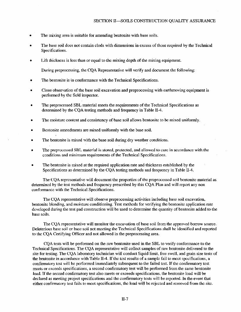
SECTION 11-SOILS CONSTRUCTION QUALITY ASSURANCE
The mixing area is suitable for amending bentonite with base soils.
The base soil does not contain clods with dimensions in excess of those required by the Technical Specifications.
Lift thickness is less than or equal to the mixing depth of the mixing equipment.
During preprocessing, the CQA Representative will verify and document the following:
The bentonite is in conformance with the Technical Specifications.
Close observation of the base soil excavation and preprocessing with earthmoving equipment is performed by the field inspector.
The preprocessed SBL material meets the requirements of the Technical Specifications as determined by the CQA testing methods and frequency in Table 11-4.
The moisture content and consistency of base soil allows bentonite to be mixed uniformly.
Bentonite amendments are mixed uniformly with the base soil.
The bentonite is mixed with the base soil during dry weather conditions.
The preprocessed SBL material is stored, protected, and allowed to cure in accordance with the conditions and minimum requirements of the Technical Specifications.
The bentonite is mixed at the required application rate and thickness established by the Specifications as determined by the CQA testing methods and frequency in Table II-4.
The CQA representative will document the properties of the preprocessed soil bentonite material as determined by the test methods and frequency prescribed by this CQA Plan and will report any non conformance with the Technical Specifications.
The CQA representative will observe preprocessing activities including base soil excavation, bentonite blending, and moisture conditioning. Test methods for verifying the bentonite application rate developed during the test pad construction will be used to determine the quantity of bentonite added to the base soils.
The CQA representative will monitor the excavation of base soil from the approved borrow source. Deleterious base soil or base soil not meeting the Technical Specifications shall be identified and reported to the CQA Certifying Officer and not allowed in the preprocessing area.
CQA tests will be performed on the raw bentonite used in the SBL to verify conformance to the Technical Specifications. The CQA representative will collect samples of raw bentonite delivered to the site for testing. The CQA laboratory technician will conduct liquid limit, free swell, and grain size tests of the bentonite in accordance with Table 11-4. If the test results of a sample fail to meet specifications, a confirmatory test will be performed immediately subsequent to the failed test. If the confirmatory test meets or exceeds specifications, a second confirmatory test will be performed from the same bentonite load. If the second confirmatory test also meets or exceeds specifications, the bentonite load will be declared as meeting project specifications and the confirmatory tests will be reported. In the event that either confirmatory test fails to meet specifications, the load will be rejected and removed from the site.
11-7

SECTION II-SOILS CONSTRUCTION QUALITY ASSURANCE
Test methods for verifying the bentonite application rate developed during the test pad construction will be used to determine the quantity of bentonite added to the base soils. The CQA representative will observe mixing and test the bentonite-amended soil prior to placing it in the ICDF landfill. CQA tests listed in Table 11-4 that do not have acceptance criteria specified in the Technical Specifications will be performed for information purposes.
4.2.7.2 Placement
Prior to the placement of the SBL, the CQA representative will verify and document the following:
The Phase 2 test pad has been constructed with the proposed liner material and production scale equipment to confirm compaction procedures on a 3H: 1V slope. In addition, field testing shall be completed on the test pad to confirm SBL placement specifications will be achieved on the sloped portions of the ICDF landfill.
All or an approved portion of the excavation are complete, and that a survey has been conducted to verify that the subgrade grades and elevations conform to the Construction Drawings.
The prepared subgrade meets specifications as determined by the test requirements of this CQA Plan.
The surface of the subgrade is free of debris, wet and soft areas, ponded water, vegetation, mud, ice, or frozen material.
If frozen subgrade material is encountered, it is removed and replaced in accordance with the Technical Specifications.
The SBL material is free of roots, stumps, vegetation, or any other type of deleterious material that may impact the performance of the placed SBL.
The SBL material does not contain stones with dimensions in excess of those required by the Technical Specifications.
The SBL material meets or exceeds the requirements of the Technical Specifications as determined by the CQA testing methods and frequency in Table II-4.
The moisture content of the SBL material is uniform.
During placement and compaction of the SBL, the CQA Team will verify and document the following :
Close observation of the placement and compaction of SBL material with earthmoving equipment is performed by the field inspectors.
The SBL material meets the requirements of the Technical Specifications as determined by the CQA testing methods and frequency in Table 11-4 and maximum allowable failure rates in Table II-5.
The SBL is placed in accordance with the conditions and minimum requirements of the Technical Specifications.
11-8

SECTION 11-SOILS CONSTRUCTION QUALITY ASSURANCE
Each lift is compacted to the required thickness and minimum dry unit weight within the range of moisture contents established by the Technical Specifications as determined by the CQA testing methods and frequency in Table 11-4.
Shelby tube samples are collected for laboratory permeability testing at the frequency specified in Table 11-4.
Perforations in the SBL at testing and sampling locations are repaired in accordance with the Technical Specifications.
The SBL is maintained until it is covered by the geomembrane liner in accordance with the Technical Specifications.
In areas of inaccessibility by the Cat 285 compactor, in areas of nonstandard SBL placement, and/or in areas of different compaction methods, more frequent testing shall be performed due to thinner lift thicknesses to achieve equivalent compactive effort. Each lift, no matter how thin, will be tested for density and moisture in accordance with Table II-4.
The CQA representative will document the properties of the SBL as determined by the test methods and frequency prescribed by this CQA Plan and will report any non conformance in accordance with the non conformance reporting described in Section VIII.
The CQA representatives will collect samples immediately after a loose lift of SBL materials has been placed for property tests prior to compaction. Once compacted, nuclear density meter test methods will be used for testing the in situ compacted dry unit weight and moisture content of the SBL. Standard Count Calibration and moisture content tests will be used to calibrate the reading of the nuclear density meter and, in cases of uncertainty, with the nuclear density meter readings. Standard Count Calibration and in situ moisture content tests using the oven dry method shall be performed at the frequencies specified in Table 11-3. The results of the oven dry moisture content tests shall be compared with the field moisture content results to determine a field moisture correction factor. The CQA representative shall adjust the field moisture correction factor as test data is collected (Le., moving average). The CQA representative will collect Shelby tube samples of the SBL for laboratory permeability tests as specified in Table II-4.
If in-place density test results fail to meet specifications, a confirmatory test will be performed immediately adjacent to (within 3 ft of) the failed test. If the confirmatory test meets or exceeds specifications, a second confirmatory test will be performed at a second location immediately next to (within 3 ft of) the failed test. If the second confirmatory test also meets or exceeds specifications, the area will be declared as meeting project specifications and the confirmatory tests will be reported. In the event that either confirmatory test fails to meet specifications, additional testing will be performed to identify the limits of the area that does not meet project specifications. All confirmatory tests, failing tests, and retests shall be recorded in the CQA representative’s field book or compaction testing form. The approximate location and elevation of each test shall be recorded based on a predefined grid system or survey.
Rapid laboratory permeability tests such as the constant volume tests should be used when possible to determine permeability. Once the sample has achieved the specified permeability, the test result will be reported immediately to the CQA certifying engineer. The number of failing tests shall be less than the maximum percentage of failing tests specified in Table 11-5. The maximum percentage of failing tests are anticipated to cover mistakes, math errors, or other unknown circumstances that are not discovered until after the layer is covered with the succeeding layer(s).
11-9

SECTION II-SOILS CONSTRUCTION QUALITY ASSURANCE
If a defective area is discovered in the SBL other than a failed in-place density test, the CQA representative will determine the extent and nature of the defect. If the defect is indicated by an unsatisfactory test result, the CQA representative will determine the extent of the defective area by additional tests, observations, a review of records, or other means that the CQA representative deems appropriate. If the defect is related to adverse site conditions, such as excessively wet soils or surface desiccation, the CQA representative will define the limits and nature of the defect by testing or observation. After the extent and nature of a defect is determined and has been remedied by the construction subcontractor, the CQA representative will verify that the deficiency is corrected by retesting repaired areas before any additional work is performed by the construction subcontractor in the area of the deficiency.
The testing frequency during the SBL construction may be increased or modified at the discretion of the CQA certifying engineer when visual observations of construction performance indicate potential problems or when field experience with the proposed SBL material have been obtained.
During construction, the frequency of testing may be increased by the CQA representative during adverse weather conditions, if equipment breaks down, at the start and finish of grading, if the material fails to meet the requirements of the Technical Specifications, or the extent of the work area is reduced.
The construction subcontractor will repair all perforations in the SBL resulting from sampling and other CQA activities in accordance with the Technical Specifications. These perforations shall be identified to the construction subcontractor by the CQA representative. All repairs shall be inspected by the CQA representative.
The construction subcontractor will be required to use all means necessary to protect all prior work, as well as all materials and completed work of other sections. In the event of damage, the construction subcontractor will be required to immediately make all repairs and replacements necessary. The CQA representative will verify and document that all damages are repaired.
4.2.2 Layer Completion Certification
The construction subcontractor will be required to notify the CQA representative when an area of SBL is complete prior to constructing the overlying layer. The CQA certifying engineer shall provide a certificate of layer completion to the construction subcontractor and the ICDF project engineer certifying that the area is complete prior to placement of subsequent overlying material. The CQA certifying engineer shall provide a certificate of layer completion to the construction subcontractor and the ICDF project engineer after placement of subsequent overlying material only if the construction subcontractor and the ICDF project engineer agree to proceed with the overlying material prior to CQA certification.
The CQA certifying engineer shall ensure all CQA tests are complete and that all defective areas have been repaired and retested in accordance with this CQA Plan and the Technical Specifications. The certificate of layer completion will indicate that the SBL meets the low permeability requirement based on laboratory tests and the thickness of the SBL meets the minimum requirement specified in the Technical Specifications.
11-10
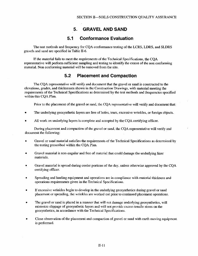
SECTION 11-SOLS CONSTRUCTION QUALITY ASSURANCE
5. GRAVEL AND SAND
5.1 Conformance Evaluation
The test methods and frequency for CQA conformance testing of the LCRS, LDRS, and SLDRS gravels and sand are specified in Table 11-6.
If the material fails to meet the requirements of the Technical Specifications, the CQA representative will perform sufficient sampling and testing to identify the extent of the non conforming material. Non conforming material will be removed from the site.
5.2 Placement and Compaction
The CQA representative will verify and document that the gravel or sand is constructed to the elevations, grades, and thicknesses shown in the Construction Drawings, with material meeting the requirements of the Technical Specifications as determined by the test methods and frequencies specified within this CQA Plan.
Prior to the placement of the gravel or sand, the CQA representative will verify and document that:
The underlying geosynthetic layers are free of holes, tears, excessive wrinkles, or foreign objects.
All work on underlying layers is complete and accepted by the CQA certifying officer.
During placement and compaction of the gravel or sand, the CQA representative will verify and document the following:
Gravel or sand material satisfies the requirements of the Technical Specifications as determined by the testing prescribed within the CQA Plan.
Gravel material is non-angular and free of material that could damage the underlying liner materials.
Gravel material is spread during cooler portions of the day, unless otherwise approved by the CQA certifying officer.
Spreading and hauling equipment and operations are in compliance with material thickness and operations requirements given in the Technical Specifications.
If excessive wrinkles begin to develop in the underlying geosynthetics during gravel or sand placement or spreading, the wrinkles are worked out prior to continued placement operations.
The gravel or sand is placed in a manner that will not damage underlying geosynthetics, will minimize slippage of geosynthetic layers and will not provide excess tensile stress on the geosynthetics, in accordance with the Technical Specifications.
Close observation of the placement and compaction of gravel or sand with earth moving equipment is performed.
11-1 1

SECTION 11-SOILS CONSTRUCTION QUALITY ASSURANCE
5.3 Construction Quality Assurance Evaluation
No density tests will be conducted on the gravel or sand. If the CQA representative suspects damage to pipes or underlying geosynthetic, the construction subcontractor will be required to expose the potentially damaged materials and repair any observed damage.
5.4 Layer Completion Certification
The construction subcontractor will be required to notify the CQA representative when an area of the LCRS gravel is complete prior to constructing the overlying layer. The CQA certifying officer shall provide a certificate of layer completion to the construction subcontractor and the ICDF project engineer certifying that the area is complete prior to placement of subsequent overlying material. The CQA certifying engineer shall provide a certificate of layer completion to the construction subcontractor and the ICDF project engineer after placement of subsequent overlying material only if the construction subcontractor and the ICDF project engineer agree to proceed with the overlying material prior to CQA certification.
11- 12

SECTION 11-SOILS CONSTRUCTION QUALITY ASSURANCE
6. OPERATIONS LAYER
The CQA representative will verify and document that the operations layer is constructed to the elevations, grades, and thicknesses shown in the Construction Drawings, with material meeting the requirements of the Technical Specifications as determined by the test methods and frequencies specified within this CQA Plan.
Prior to the placement of the operations layer, the CQA representative will verify and document the following:
The underlying geosynthetic layer is free of holes, tears, excessive wrinkles, or foreign objects.
All work on underlying layers is complete and accepted by the CQA certifying officer.
During placement of the operations layer, the CQA representative will verify and document that:
The soil is suitable and satisfies the requirements of the Technical Specifications as determined by the test methods and frequencies prescribed in Table 11-7.
The operations soil is placed in accordance with the Technical Specifications and Construction Drawings.
The lift thicknesses and total thickness of the operations layer agree with the requirements of the Construction Drawings.
If excessive wrinkles begin to develop in the underlying geosynthetics during material placemerit or spreading, the wrinkles are worked out prior to continued placement operations.
The operations layer is placed in a manner that will not damage underlying geosynthetics, will minimize slippage of geosynthetic layers, and will not provide excess tensile stress on the geosynthetics, in accordance with the Technical Specifications.
Spreading and hauling equipment and operations are in compliance with material thickness and operations requirements given in the Technical Specifications.
The operations layer is placed on the side slopes to the limits shown in the Construction Drawings.
No operations layer material is placed or compacted during periods of unfavorable weather conditions, such as after heavy rains or snow, in accordance with requirements given in the Technical Specifications.
6.1 Conformance Evaluation
The test methods and frequencies for CQA conformance testing for the operations layer are specified in Table 11-7.
If damage to underlying geosynthetics is suspected, the CQA representative will require that the overlying operations layer material be removed to expose the geosynthetics.
11-13

SECTION 11-SOILS CONSTRUCTION QUALITY ASSURANCE
The construction subcontractor will be required to use all means necessary to protect all prior work, as well as all materials and completed work of other sections. In the event of damage, the construction subcontractor will be required to immediately make all repairs and replacements necessary. The CQA representative will verify and document that all damages are repaired.
11-14

SECTION 11-SOILS CONSTRUCTION QUALUY ASSURANCE
7. SOIL SURVEYING
A survey shall be performed by or under the direction of a professional land surveyor registered in the State of Idaho. The surveyor shall independently survey the elevations and grades of the soil layers including, but not limited to, those listed below:
Landfill
Top of prepared subgrade
Top of SLDRS sand
Top of LCRS gravel
Top of SBL
Top of operations layer.
Evaporation Pond
Top of prepared subgrade
Top of base soil
Top of LDRS gravel
Top of operations layer.
Surveys will be performed on the base and side slopes of the landfill, to confirm that the grades and elevations in the field agree with those shown in the Con&uction Drawings and minimum acceptable tolerances required in the Technical Specifications. The surveys will be performed in accordance with the requirements described in Section VIII. The results of the survey conducted by the surveyor will be compiled in a report signed by the surveyor and the CQA certifying officer.
The surveyor will be required to survey each soil layer of the liner system for the ICDF landfill and evaporation ponds in accordance with the requirements of this CQA Plan. A Record Drawing will be submitted to the CQA certifying officer by the surveyor before the placement of the next liner system layer. The surveys will be conducted at a 50-ft grid across the entire area of the survey. The survey shall include, but not be limited to, the following features of the landfill and evaporation ponds:
e Toeofslope
Crest of slope
Grade breaks
Anchor trench
SLDRS, LDRS, and LCRS sumps.
11- 15
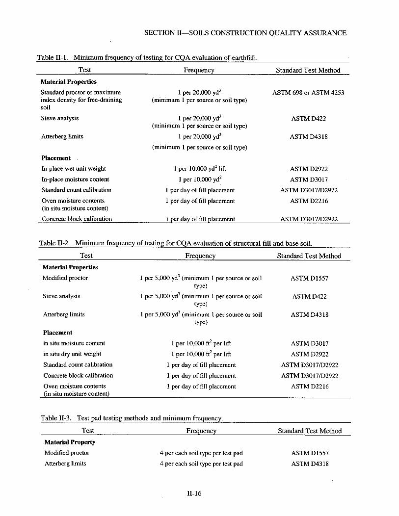
SECTION 11-SOLS CONSTRUCTION QUALITY ASSURANCE
Table 11-1. Minimum frequency of testing for CQA evaluation of earthfill.
Test Frequency Standard Test Method Material Properties Standard proctor or maximuni index density for free-draining soil
Sieve analysis 1 per 20,000 yd3 ASTM D422
Atterberg limits 1 per 20,000 yd3 ASTM D43 18
1 per 20,000 yd3 (minimum 1 per source or soil type)
ASTM 698 or ASTM 4253
(minimum 1 per source or soil type)
(minimum 1 per source or soil type)
Placement In-place wet unit weight
In-place moisture content
1 per 10,OOO yd2 lift
1 per 10,000 yd2
ASTM D2922
ASTM D3017
Standard count calibration 1 per day of fill placement ASTM D3017D2922
Oven moisture contents (in situ moisture content)
1 per day of fill placement ASTM D22 16
Concrete block calibration 1 per day of fill placement ASTM D3017D2922
-- Table 11-2. Minimum frequency of testing for CQA evaluation of structural fill and base soil.
Test Frequency Standard Test Method Material Properties Modified proctor
Sieve analysis
Atterberg limits
Placement in situ moisture content
1 per 5,000 yd3 (minimum 1 per source or soil
1 per 5,000 yd3 (minimum 1 per source or soil
1 per 5,000 yd3 (minimum 1 per source or soil
ASTM D 1557 type)
type)
type)
ASTM D422
ASTM D43 18
1 per 10,000 ft2 per lift ASTM D3017
in situ dry unit weight
Standard count calibration
I per 10,000 ft2 per lift
1 per day of fill placement
ASTM D2922
ASTM D3017D2922
Concrete block calibration
Oven moisture contents (in situ moisture content)
1 per day of fill placement
1 per day of fill placement
ASTM D3017D2922
ASTM D22 16
Table 11-3. Test pad testing methods and minimum frequency.
Test Frequency Standard Test Method Material Property Modified proctor
Atterberg limits
4 per each soil type per test pad
4 per each soil type per test pad
ASTM D1557
ASTM D43 18
- 11-16
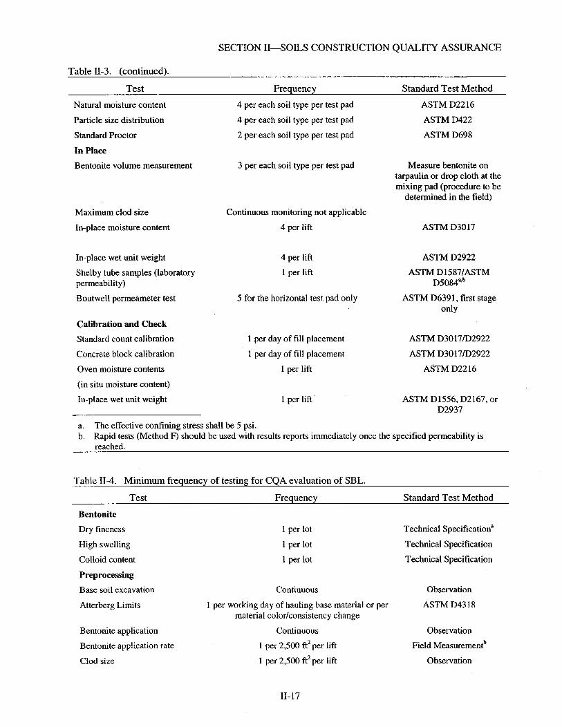
SECTION 11-SOILS CONSTRUCTION QUALITY ASSURANCE
Table 11-3. (continued).
Test Frequency Standard Test Method
Natural moisture content
Particle size distribution
Standard Proctor
In Place Bentonite volume measurement
Maximum clod size
In-place moisture content
In-place wet unit weight
Shelby tube samples (laboratory permeability)
Boutwell permeameter test
Calibration and Check Standard count calibration
Concrete block calibration
Oven moisture contents
(in situ moisture content)
In-place wet unit weight
4 per each soil type per test pad
4 per each soil type per test pad
2 per each soil type per test pad
3 per each soil type per test pad
Continuous monitoring not applicable
4 per lift
4 per lift
1 per lift
5 for the horizontal test pad only
1 per day of fill placement
1 per day of fill placement
1 per lift
1 per lift
ASTM D22 16 ASTM D422 ASTM D698
Measure bentonite on tarpaulin or drop cloth at the mixing pad (procedure to be
determined in the field)
ASTM D3017
ASTM D2922 ASTM D1587/ASTM
D5084"b ASTM D6391, first stage
only
ASTM D3017/D2922 ASTM D3017D2922
ASTM D22 16
ASTM D1556, D2167, or D2937
a. b.
The effective confining stress shall be 5 psi. Rapid tests (Method F) should be used with results reports immediately once the specified permeability is reached.
Table 11-4. Minimum frequency of testing for CQA evaluation of SBL.
Test Freauencv Standard Test Method
Bentonite Dry fineness
High swelling
Colloid content
Preprocessing Base soil excavation
Atterberg Limits
Bentonite application
Bentonite app!ication rate
Clod size
1 per lot
1 per lot
1 per lot
Continuous
1 per working day of hauling base material or per material colorkonsistency change
Continuous
1 per 2,500 ft2 per lift
1 per 2,500 ft2 per lift
Technical specification"
Technical Specification
Technical Specification
Observation
ASTM D43 18
Observation
Field Measurementb
Observation
11- 17

SECTION 11-SOILS CONSTRUCTION QUALITY ASSURANCE
Table 11-4. (continued).
Test Frequency Standard Test Method Curing' 1 per 12 hours Observation
Pre-Compaction Lift thicknessd 1 per 2,500 ft2 per lift Field Measurement
Percent fines 1 per 1,OOO yd3 ASTM D 1 140 (minimum of 1 per day of placement)
1 per 1,OOO yd3 with a minimum of 1 per day of placement
Percent gravel ASTM D422
Atterberg limits 1 per 1,OOO yd3 ASTM D43 18 (minimum of 1 per day of placement)
Placement Continuous Observation
Post Compaction Rapid moisture content 5 per acre per lift ASTM D3017 Rapid dry unit weight ASTM D2922 5 per acre per lift
Oven moisture content
Standard count calibration
1 per 10 rapid moisture content
1 per day of pla, rement
ASTM D22 16 ASTM D2922/ASTM D3017
Concrete block calibration 1 per day of fill placement
Shelby tube samples (laboratory permeability)
1 per acre per lift
ASTM D3017D292" ASTM D 15 87/ ASTM D5084e.f
Number of passesg Observe 1 per acre per lift Observation
Construction oversight Continuous 0bservat.ion
a. b.
The test method is described in the technical specification. The test method for determining the application rate of bentonite shall be the site-specific method selected for the test pad construction during Phase 1. Curing is stockpiling the SBL material for 12 hours to allow the bentonite to hydrate. A loose lift thickness is such that the compacted thickness is 6 in. or less. The effective confining stress shall be 5 psi. Rapid tests (Method F) should be used with results reported immediately once the specified permeability is reached. A single pass is defined as forward and back.
c. d. e. f.
g.
Table 11-5. Maximum percentage of failed tests for CQA evaluation of soil bentonite liner.
Test Maximum percentage Percent gravel
Clod size
Rapid moisture content
Rapid dry unit weight
5% not concentrated in one lift or one area
10% not concentrated in one lift or one area
3% not concentrated in one lift or one area, and no water content less than 2% or more than 3% of the specified value
3% not concentrated in one lift or one area, and no dry unit weight less than 5 pcf below the specified value
11-18

SECTION 11-SOILS CONSTRUCTION QUALITY ASSURANCE
Table 11-5. (continued).
Test Maximum percentage
Shelby tube samples (laboratory 5% not concentrated in one lift or one area permeability)
Table 11-6. Minimum frequency of testing for CQA evaluation of gravel and sand.
Test Frequency Standard Test Method
Pre-Placement Sieve analysis 1 per 2,500 yd3 ASTM D422
Table 11-7. Minimum frequency of testing for CQA evaluation of operations layer.
Test Frequency Standard Test Method
Pre-Placement Sieve analysis 1 per 5,000 yd3 placed (minimum 1 per source) ASTM D422
Table 11-8. Minimum frequency of testing for CQA evaluation of prepared subgrade.
Test Frequency Standard Test Method -
Material Propertiesa Standard proctor or maximum index density for free-draining soil
Sieve analysis 1 per 250,000 ft2 ASTM D422
Atterberg limits 1 per 250,000 ft2 ASTM D43 18
In Placeb In-place wet unit weight
In-place moisture content
1 per 250,000 ft2 (minimum 1 per source or soil type)
ASTM 698 or ASTM 4253
(minimum 1 per source or soil type)
(minimum 1 per source or soil type)
1 per 10,000 ft2
1 per 10,oOo ft2
ASTM D2922
ASTM D3017
ASTM D3017/D2922
ASTM D3017D2922
Standard count calibration
Concrete block calibration
Over moisture content (in situ moisture content)
a. Prior to final grading. b. After final grading.
1 per day when in place tests are performed
1 per day when in place tests are performed
1 per day when in place tests are performed
11- 19

SECTION III-GEOSYNTHETIC CLAY LINER CONSTRUCTION QUALITY ASSURANCE
Section Ill-Geosynthetic Clay Liner Construction Quality Assurance
1. GEOSYNTHETIC CLAY LINER MANUFACTURE AND DELIVERY
1.1 Labeling
The CQA representative will verify and document that the GCL manufacturer has labeled each roll of GCL and includes the information required by the Technical Specifications.
The CQA representative will examine GCL rolls upon delivery and deviation from the above requirements will be reported to the CQA certifying officer prior to installation of the GCL.
1.2 Transportation and Handling
The CQA representative will observe and document that the type of GCL handling equipment used by the installer minimizes damage to the material.
Upon delivery at the site, the CQA representative conducts a visual inspection of all rolls for defects and for damage. This examination will be conducted without unrolling rolls unless visible defects or damages are found. The CQA representative will indicate to the CQA certifying officer:
0 Any rolls that should be unrolled to allow for their inspection
Any rolls, or portions thereof, that should be rejected and removed from the site because they have severe flaws
0 Any rolls that include minor repairable flaws.
1.3 Storage
The CQA representative will verify and document that storage of the GCL is in accordance with the Technical Specifications.
1.4 Inventory
All geosynthetic materials that arrive on-site will be inventoried in accordance with INEEL PRD) 5008 and this CQA Plan. The inventory shall include the specific roll numbers delivered with each shipment. The inventory will be compared to the QC testirfg information supplied by the manufacturer to ensure that the material tested is the same material that was delivered to the site. Material for which QC testing data has been supplied will be sampled for conformance testing. Conformance samples may be obtained by the CQA representative at the manufacturing plant or taken upon delivery of the material to the site by a CQA representative.
In addition to the requirements in PRD-5008, as shipments arrive at the site, a CQA representative will monitor the unloading operations and will inventory the material. Rolls selected for conformance testing should be set aside for sampling as soon as possible.
The CQA representative shall record the information listed below, at a minimum, for each roll.
111- 1

SECTION III-GEOSYNTHETIC CLAY LINER CONSTRUCTION QUALITY ASSURANCE
e
e
e
e
e
e
e
e
e
e
e
e
e
e
Manufacturer-Indicate the manufacturer of the material that is being inventoried, which may not be the same as the installer.
Date of Inventory-Date that the material was inventoried.
Date of Delivery-Enter date when the truck arrived on-site, if known.
Truck Type-Indicate type of truck used for shipping geosynthetics (flatbed [covered or uncovered], box trailer, etc.).
Bill-of-Lading No.-If the bill-of-lading is available, indicate number and date (also attach copy to inventory form).
CQA Representative-Indicate name of CQA representative performing inventory.
Unloading Equipment-Indicate the type and model number of the equipment unloading the geosynthetic material. Also note any special attachments that are used to unload the material (stinger, straps, forks, etc.).
Weather Conditions-Describe the weather conditions, including temperature, wind, cloud cover, and precipitation, during unloading and conformance sampling operation.
Material Type-Indicate type of geosynthetic material.
Roll Number-Indicate each roll number that is indicated on the roll. The roll numbers contain a variety of information regarding the material and the manufacturing process.
Lot Number-Lot number.
Roll (L x W)-Indicate the roll width as indicated on the roll label. If two materials are bonded together (i.e., geonedgeotextile), obtain measurements for both materials.
Area (sq. ft)-Indicate the total square footage of the roll.
Damage Remarks-Document any visible damage to the roll. If possible, indicate if damage was present prior to unloading or if it occurred during unloading.
The CQA representative will be responsible for affixing yellow “Quality Hold for Lnspection” (INEEL form 416.23) tags provided by BBWI to each roll immediately after the material is delivered to the site. After the inventory has been completed and the conformance test results have been reviewed, the CQA representative shall remove the yellow “Quality Hold for Inspection” Tag and attach one of the following INEEL tags as appropriate:
e Green tag-Quality Accepted (INEEL form 416.22)
e Green tagkicker-Acceptance (INEEL form 432.69/69A)
e Red tag-Non conformance (INEEL form 230.3)
e Red tag--Conditional use (INEEL form 230.4)
111-2

SECTION III-GEOSYNTHETIC CLAY LINER CONSTRUCTION QUALITY ASSURANCE
The CQA representative shall immediately notify the STWconstruction coordinator if a nonconforming or conditional use tag is attached to any of the inventoried items.
Items that are restricted from further use until the inspections have been completed shall be clearly delineated by the CQA representative. Accepted materials shall be kept separate or clearly delineated from inventoried and approved items to the extent possible. The CQA representative shall be responsible for coordinating with the construction subcontractor during material delivery, so that the material is not moved more than necessary after it is unloaded and damage due to handling is minimized.
The CQA representative shall perform the inventory immediately after the material arrives on the site to avoid delaying construction. The CQA representative shall be responsible for verifying that only accepted material is installed at the ICDF landfill and evaporation pond and all inventories and inspections are documented and maintained in accordance with PRD-5008.
1.5 Quality Assurance Conformance Testing
Either at the manufacturers’ plant or upon delivery of the rolls of GCL, the CQA representative will ensure that samples are removed at the specified frequency and forwarded to the Geosynthetics CQA Laboratory for testing to verify and document conformance with the Technical Specifications.
Conformance samples will be taken across the entire width of the roll and will not include the first 3 ft along the length of the roll. Unless otherwise specified, samples will be 1.5-ft (minimum) long by the roll width. The CQA representative will mark the machine direction on the samples with an arrow.
Unless otherwise specified, samples will be taken at a rate of one per lot or one per 100,OOO ft2, whichever is greater. These samples will be tested for the following:
0 Bentonite Moisture Content ASTM I34643
0 GCL Permeability
0 Bentonite Mass per Unit Area ASTM D5993
0 Swell Index Test ASTM D5890.
Test shall be conducted in accordance with the test procedure presented in the Technical Specifications.
The CQA representative will examine all results from laboratory conformance testing and will compare the results to the specifications presented in the Technical Specifications. In addition, the CQA representative will report any non conformance to the CQA certifying officer as soon as practical after the test results become available.
The following procedure will apply whenever a sample fails a conformance test that is conducted by the Geosynthetics CQA Laboratory:
0 The construction subcontractor will be required to replace the roll (or rolls) of GCL not in conformance with the specifications with a roll that meets the requirements of the Technical Specifications .
111-3

SECTION III-GEOSYNTHETIC CLAY LINER CONSTRUCTION QUALITY ASSURANCE
The CQA representative will ensure that conformance samples are removed for testing by the Geosynthetics CQA Laboratory from the closest numerical roil on both sides of the roll from which the failing sample was obtained. These two samples must pass the above conformance tests. If either of these samples fail to meet the requirements, samples will be collected from the five numerically closest untested rolls on both sides of the failed samples and tested by the Geosynthetics Laboratory. These 10 samples must pass the above conformance tests. If any of these samples fail, a sample from every roll of GCL on-site and a sample from every roll that is subsequently delivered from the same manufacturer must be conformance tested by the Geosynthetics CQA Laboratory.
The CQA representative will document actions taken in conjunction with conformance test failures and report all actions to the certifying officer.
111-4

SECTION III-GEOSYNTHETIC CLAY LINER CONSTRUCTION QUALITY ASSURANCE
2. GEOSYNTHETIC CLAY LINER INSTALLATION
2.1 Earthworks
2.1.1 Surface Preparation
For fill surfaces that will underlay a GCL layer, prior to placement of GCL, the CQA representative will verify and document the following:
The surface of the fill does not contain holes, ruts, protrusions, or other surface irregularities in excess of those dimensions specified by the Technical Specifications.
The surface of the fill has been compacted to form a firm stable base.
The surface of the fill is free of any type of deleterious material that may cause damage to GCL, including debris, organic material, frozen soil, ice, and rocks.
The surface of the fill is free of standing water or excessive moisture.
The construction subcontractor has certified in writing that the surface on which the GCL will be installed is acceptable.
The subgrade surface will be inspected immediately prior to commencement of GCL installation. If any change in the surface requires repair work, in accordance with the Technical Specifications, the construction subcontractor will be responsible for repairing the fill surface.
A certificate of subgrade surface acceptance will be required from the construction subcontractor. The CQA representative shall verify that the subgrade is accepted by the GCL installer immediately prior to commencement of GCL installation.
After the surface on which the GCL is to be installed has been accepted by the construction subcontractor, it will be the CQA representative’s responsibility to indicate to the CQA certifying officer any change in the underlying layer that may, in accordance with the Technical Specifications, require repair work. If the CQA certifying officer requires repair work, it will be the responsibility of the construction subcontractor to repair the underlying layer.
2.1.2 Anchor Trenches and Sumps
Prior to placement of geosynthetics in the anchor trenches or sumps, the CQA representative will verify and document the following:
The sumps and anchor trenches are excavated to the grades and dimensions shown in the construction drawings. Any anomalies in the soil encountered during excavation will be brought to the attention of the ICDF project engineer and removed as directed.
The anchor trench excavation surface is prepared for installation of geosynthetics, with rounded comers, and free of loose soil or deleterious material.
111-5

SECTION 111-GEOSYNTHETIC CLAY LINER CONSTRUCTION QUALITY ASSURANCE
After geosynthetics deployment into the anchor trench is complete, the CQA representative will verify and document that the bacidill for the geosynthetic anchor trenches is placed and compacted in accordance with the Technical Specifications.
2.2 Geosynthetic Clay Liner Deployment
2.2.1 Field Panel Identification
A field panel is the unit area of GCL that is to be placed in the field, Le., a field panel is a roll or a portion of roll cut in the field.
The CQA representative shall track the placement location of each GCL panel by assigning an identification code (number or letter-number) or by an equivalent tracking method. The identification method shall be agreed upon by the CQA certifying officer and the construction subcontractor. This field panel identification scheme should be as simple and logical as possible. (Note: manufacturing plant roll numbers are usually cumbersome and are not related to location in the field.) It will be the responsibility of the construction subcontractor to ensure that each field panel placed is marked with the manufacturing plant roll number. The roll number will be marked in the center of the panel in a color to allow for easy inspection.
The CQA representative will establish a table or chart showing correspondence between manufacturing plant roll numbers and field panel identification codes. The field panel identification code will be used for all CQA records.
2.2.2 Field Panel Placement
2.2.2.1 lnstallation Schedule. The CQA representative will evaluate significant changes in the . schedule proposed by the construction subcontractor and advise the CQA certifying officer on the acceptability of that change. The CQA representative will verify and document that the condition of the underlying layer has not changed detrimentally during installation. Any damage to the surface of the underlying layer will be repaired by the construction subcontractor in accordance with the Technical Specifications.
2.2.2.2 Weather Conditions. The CQA representative will verify and document that GCL is not placed during inclement weather conditions, as specified within the Technical Specifications. Additionally, the CQA monitor will verify and document that the existing underlying layer has not been damaged by weather conditions.
2.2.2.3 damage. The CQA representative will inform the construction subcontractor which panels, or portions of panels, should be rejected, repaired, or accepted. Damaged panels or portions of damaged panels that have been rejected by the CQA representative will be marked, and their removal from the work area will be documented by the CQA representative.
Damage. The CQA representative will visually observe each panel, after placement, for
2.2.2.4 document that the seam overlaps and bentonite material placed between panels, if required, along the seams meets specification guidelines. The CQA representative will verify overlap width and will observe bentonite seal placement.
Seam Overlap and Bentonite Seal. The construction subcontractor will observe and
111-6
SECTION III-GEOSYNTHETIC CLAY LINER CONSTRUCTION QUALITY ASSURANCE
2.2.3 Field Panel Protection
The CQA representative will observe and document that the GCL is completely covered with geomembrane at the end of each workday and protected from damage and hydration due to weather. The CQA representative will verify and document that equipment does not operate directly on the GCL and that a smooth rub sheet is used to maneuver textured geomembrane over the GCL to prevent damage to the GCL.
2.3 Defects and Repairs
2.3.1 Identification
All seams and non-seam areas of the CJCL will be inspected by the CQA representative for evidence of defects, holes, contamination of geotextiles, displaced panels, premature hydration, and any sign of contamination by foreign matter. The CQA representative will observe and document repair procedures described below.
2.3.2 Repair Procedures
Prior to cover material placement, damage to the GCL shall be identified and repaired by the installer.
2.3.2.7 Rip and Tear Repair (Flat Surfaces). Rips or tears may be repaired by completely exposing the affected area, removing all foreign objects or soil, and by then placing a patch cut from unused GCL over the damage (damaged material may be left in place), with a minimum overlap of 12 in. on all edges.
Accessory bentonite should be placed between the patch edges and the repaired material at a rate of a quarter pound per lineal ft of edge spread in a continuous 6-in. fillet.
2.3.2.2 the same procedures above, however, the overlapped edges of the patch should be wide enough to ensure the patch will keep its position during backfill or cover operations.
Rip and Tear Repair (Slopes). Damaged GCL material on slopes shall be repaired by
2.3.2.3 orientation. The adjusted panel shall then be inspected for any geotextile damage or bentonite loss. Damage shall be repaired by the above procedure.
Displaced Panels. Displaced panels shall be adjusted to the correct position and
2.3.2.4 Premature Hydration. If the GCL is subjected to premature hydration, the construction subcontractor shall notify the CQA certifying officer for a site-specific determination as to whether the material is acceptable or if alternative measures must be taken to ensure the quality of the design dependent upon the degree of damage.
111-7

SECTION IV-GEOMEMBRANE CONSTRUCTION QUALITY ASSURANCE
Section IV-Geomembrane Construction Quality Assurance
1. GEOMEMBRANE MATERIAL
1.1 Labeling
The CQA representative will verify and document that the geomembrane manufacturer has labeled each roll of geomembrane and includes the information required by the Technical Specifications.
The CQA representative will examine geomembrane rolls upon delivery and deviation from the above requirements will be reported to the CQA certifying officer prior to installation of the geomembrane.
1.2 Transportation and Handling
Upon delivery at the site, the CQA representative will conduct a visual inspection of all rolls for defects and for damage. This examination will be conducted without unrolling rolls unless visible defects or damages are found. The CQA representative will indicate the following to the CQA certifying officer:
0
0
Any rolls that should be unrolled to allow for their inspection
Any rolls, or portions thereof, which should be rejected and removed from the site because they have severc flaws
0 Any rolls that include minor repairable flaws.
1.3 Storage
The CQA representative will verify and document that storage of the geomembrane is in accordance with the Technical Specifications.
1.4 Inventory
All geosynthetic materials that arrive on-site will be inventoried in accordance with PRD 5008 and this CQA Plan. The inventory shall include the specific roll numbers delivered with each shipment. The inventory will be compared to the QC testing information supplied by the manufacturer to ensure that the material tested is the same material that was delivered to the site. Material for which QC testing data has been supplied will be sampled for conformance testing. Conformance samples may be obtained by the CQA representative at the manufacturing plant or taken upon delivery of the material to the site by a CQA representative.
In addition to the requirements in PRD-5008, as shipments arrive at the site, a CQA representative will monitor the unloading operations and will inventory the material. Rolls selected for conformance testing should be set aside for sampling as soon as possible.
The CQA representative shall record the information listed below, at a minimum, for each roll.
IV-1
SECTION IV-GEOMEMBRANE CONSTRUCTION QUALITY ASSURANCE
Manufacturer-Indicate the manufacturer of the material that is being inventoried, which may not be the same as the installer.
Date of Inventory-Date that the material was inventoried.
Date of Delivery-Enter date when the truck arrived on-site, if known.
Truck Type-Indicate type of truck used for shipping geosynthetics (flatbed [covered or uncovered], box trailer, etc.).
Bill-of-Lading No.-If the bill-of-lading is available, indicate number and date (also attach copy to inventory form).
CQA Representative-Indicate name of CQA representative performing inventory.
Unloading Equipment-Indicate the type and model number of the equipment unloading the geosynthetic material. Also note any special attachments that are used to unload the material (stinger, straps, forks, etc.).
Weather Conditions-Describe the weather conditions, including temperature, wind, cloud cover, and precipitation, during unloading and conformance sampling operation.
Material Type-Indicate type of geosynthetic material (HDPE, geotextile, or geonet).
Roll Number-Indicate each roll number that is indicated on the roll. The roll numbers contain a variety of information regarding the material and the manufacture process. The National Seal Company, for instance, uses a number such as U6L-2456-lD12031 for HDPE where:
U = Resin type
6=60mi l
L = Liner
2456 = The resin blend number. A blend is usually a railcar load or approximately 180,000 lbs.
1 = 1991-year of production
D = April-month of production (4th month = D, 4th letter of alphabet)
12 = Date of production
03 = third roll started on the 12th (from midnight)
1 = the roll was manufactured on line No. 1
Lot Number-Lot number as indicated (2456 in example shown above).
Roll (L x W)-Indicate the roll width as indicated on the roll label. If two materials are bonded together (Le., gecnetlgeotextile), obtain measurements for both materials.
N-2
SECTION IV-GEOMEMBRANE CONSTRUCTION QUALITY ASSURANCE
0 Area (sq. ft)-Indicate the total square footage of the roll.
0 Damage Remarks-Document any visible damage to the roll. If possible, indicate if damage was present prior to unloading or if it occurred during unloading.
The CQA representative will be responsible for affixing yellow “Quality Hold for Inspection” (INEEL form 416.23) tags provided by BBWI to each roll immediately after the material is delivered to the site. After the inventory has been completed and the conformance test results have been reviewed, the CQA representative shall remove the yellow “Quality Hold for Inspection” Tag and attach one of the following INEEL tags as appropriate:
Green tag-Quality Accepted (INEEL form 416.22)
Green tadsticker-Acceptance (INEEL form 432.69/69A)
Red tag-Non conformance (INEEL form 230.3)
0 Red tag-conditional use (INEEL form 230.4)
The CQA representative shall immediately notify the STWconstruction coordinator if a non conforming or conditional use tag is attached to any of the inventoried items.
Items that are restricted from further use until the inspections have been completed shall be clearly delineated by the CQA representative. Accepted materials shall be kept separate or c!early delineated from inventoried and approved items to the extent possible. The CQA representative shall be responsible for coordinating with the construction subcontractor during material delivery, so that the material is not moved more than necessary after it is unloaded and damage due to handling is minimized.
The CQA representative shall perform the inventory immediately after the material arrives on the site to avoid delaying construction. The CQA representative shall be responsible for verifying that only accepted material is installed at the ICDF landfill and evaporation pond and all inventories and inspections are documented and maintained in accordance with PRD-5008.
1.5 Quality Assurance Conformance Testing
Either at the manufacturers’ plant or upon delivery of the rolls of geomembrane, the CQA representative will ensure that samples are removed at the specified frequency and forwarded to the Geosynthetics CQA Laboratory for testing to verify and document conformance with the Technical Specifications.
Conformance samples will be taken by the CQA representative across the entire width of the roll and will not include the first 3 ft. Unless otherwise specified, samples will be 1.5-ft (minimum) long by the roll width. The CQA representative will mark the direction of the machine used to cut the samples with an arrow.
Unless otherwise specified, samples will be taken at a rate of one per lot or one per 100,000 ft2 whichever is greater. These samples will be tested for:
Specific gravity
Thickness
N-3
SECTION IV-GEOMEMBRANE CONSTRUCTION QUALITY ASSURANCE
0 Yield strength and yield elongation
0 Carbon black content
0 Carbon black dispersion
0 Puncture resistance.
Test shall be conducted in accordance with the test procedure presented in the Technical Specifications.
The CQA representative will examine all results from laboratory conformance testing and will report any non conformance after the test results become available.
The following procedure will apply whenever a sample fails a conformance test that is conduckd by the CQA representative:
0 The construction subcontractor will be required to replace the roll (or rolls) of geomembrane in non conformance with the Technical Specifications with a roll that meets the Technical Specifications.
0 The CQA certifying officer will ensure that conformance samples are removed for testing by the Geosynthetics Laboratory from the closest numerical roll on both sides of the failed roll. These two samples must pass the above conformance tests. If either of these samples fail, samples will be collected from the five numerically closest untested rolls cn both sides of the failed sample and tested by the Geosynthetics Laboratory. These 10 samples must pass the above conformance tests. If ariy of these samples fail, a sample from every roll of geornembrane on-site and every roll . . subsequently delivered from the same manufacturer must be conformance tested by the Geosynthetics Laboratory.
Iv-4
SECTION IV-GEOMEMBRANE CONSTRUCTION QUALITY ASSURANCE
2. GEOMEMBRANE INSTALLATION
2.1 Earthworks
2.1.1 Surface Preparation
For SBL surfaces that will underlay a geomembrane layer, prior to placement of geomembrane, the CQA representative will verify and document the following:
0 The surface of the subgrade or SBL does not contain holes, depressions, or protrusions in excess of those dimensions specified by the Technical Specifications.
The surface of the subgrade or SBL has been rolled with a smooth-drum roller to form a firm stable base without ridges, wheel ruts, and surface irregularities.
0 The surface of the subgrade or SBL is free of any type of deleterious material that may cause damage to geomembrane.
The construction subcontractor has certified in writing that the surface on which the geomembrane will be installed is acceptable.
The subgrade and SBL surface will be inspected immediately prior to commencement of geomembrane installation. If any change in the surface requires repair work, in accordance with the Technical specifications, the construction subcontractor will be responsible for repairing the surface.
A certificate of subgrade surface acceptance will be required from the construction subcontractor. The CQA.representative shall verify that the subgrade is accepted by the geomembrane installer immediately prior to commencement of geornembrane installation.
After the surface on which the geomembrane is to be installed has been accepted by the construction subcontractor, it will be the CQA representative’s responsibility to indicate to the CQA certifying officer any change in the underlying layer that may, in accordance with the Technical Specifications, require repair work. If the CQA certifying officer requires repair work, it will be the responsibility of the construction subcontractor to repair the underlying layer.
2.1.2 Anchor Trenches and Sumps
Prior to placement of geosynthetics in the anchor trenches or sumps, the CQA representative will verify and document the following:
The excavation of the sumps and anchor trenches is performed in accordance with the Technical Specifications. Any anomalies in the soil encountered during excavation will be brought to the attention of the ICDF project engineer and removed as directed.
The anchor trench excavation surface is prepared for installation of geosynthetics, with rounded comers and is free of loose soil or deleterious material.
After geosynthetics deployment into the anchor trench is complete, the CQA representative will verify and document that the backfill for the geosynthetic anchor trenches is placed and compacted in accordance with the Technical Specifications and Construction Drawings.
w-5

SECTION IV-GEOMEMBRANE CONSTRUCTION QUALITY ASSURANCE
2.2 Geomembrane Deployment
2.2.1 Layout Drawing
The construction subcontractor will be required to produce layout drawings that show the geomembrane panel configuration, dimensions, details, seam locations, etc. The layout drawings must be approved by the CQA certifying officer prior to the installation of the geomembrane.
2.2.2 Field Panel Identification
A field panel is the unit area of geomembrane that is to be seamed in the field, i.e., a field panel is a roll or a portion of roll cut in the field.
The CQA representative will verify that each field panel is given an identification code (number or letter-number) consistent with the layout plan. This identification code will be agreed upon by the CQA representative and the construction subcontractor. This field panel identification code should be as simple and logical as possible. (Note: manufacturing plant roll numbers are usually cumbersome and are not related to location in the field.) It will be the responsibility of the construction subcontractor to ensure that each field panel placed is marked with the manufacturing plant roll number. The roll number will be marked in the center of the panel in a color to allow for easy inspection.
The CQA representative will establish a table or chart showing correspondence between manufacturing plant roll numbers and field panel identification codes. The field panel identification code will be used for all CQA records.
2.2.3 Field Panel Placement
2.2.3.7 the locations and positions indicated in the constructlon subcontractor’s layout plan, as approved or modified by the CQA certifying officer.
Location. The CQA representative will verify and document that field panels are installed at
2.23.2 schedule proposed by the construction subcontractor and advise the CQA certifying officer on the acceptability of that change. The CQA representative will verify and document that the condition of the underlying layer has not changed detrimentally during installation. Any damage to the surface of the underlying layer will be repaired by the construction subcontractor in accordance with the Technical Specifications.
installation Schedule. The CQA representative will evaluate significant changes in the
The CQA representative will record the identification code, location, and date of installation of each field panel.
2.2.3.3 geomembrane is not placed during inclement weather conditions as specified within the Technical Specifications.
Weather Conditions. The CQA representative will verify and document that
Additionally, the CQA representative will verify and document that the underlying layer has not been damaged by weather conditions.
2.2.3.4 prior to seaming, for damage (e.g., holes, blisters, and creases). The CQA representative will inform the construction subcontractor which panels, or portions of panels, should be rejected, repaired, or accepted.
Damage. The CQA representatives will visually observe each panel, after placement and
IV-6

SECTION IV-GEOMEMBRANE CONSTRUCTION QUALITY ASSURANCE
Damaged panels or portions of damaged panels that have been rejected by the CQA certifying officer will be marked, and their removal from the work area will be documented by the CQA representative.
2.3 Field Seaming
2.3.1 Seam Layout
The CQA certifying officer will verify and document that the seam layout shown in the Panel Layout Drawing (Part 2.2.1) is consistent with the Technical Specifications. A seam numbering system compatible with the panel numbering system will be agreed upon by the construction subcontractor and CQA certifying officer.
2.3.2 Seaming Equipment and Products
Processes approved by the Technical Specifications for field seaming are: (i) extnision seaming; and (ii) fusion seaming. Proposed alternate processes will be required to be documented and submitted to the CQA certifying officer for approval. The construction subcontractor will be required to use a pyrometer to ensure that accurate temperatures of the extrudate and seamer nozzle are being achieved.
The extrusion seaming apparatus will be equipped with gauges indicating the temperatures of the extrudate and nozzle. The construction subcontractor will be required to provide to the CQA certifying officer the manufacturers’ certification that the extrudate is compatible with the geomembrane material and is comprised of the same resin as the geomembrane.
The CQA representative will log ambient temperatures, seaming apparatus temperatures, and extrudate temperatures or fusion seaming apparatus speeds. Ambient temperatures will be measured to verify compliance with the Technical Specifications.
2.3.3 Seam Preparation
The CQA certifying officer will verify and document the following:
0 Prior to seaming, the seam area is clean and free of moisture, dust, dirt, debris, and foreign material.
0 Preparation of seams is in accordance with the Technical Specifications.
2.3.4 Weather Conditions for Seaming
The CQA representative will verify and document that weather conditions for seaming are within the limits specified in the Technical Specifications.
2.3.5 Trial Seams
The construction subcontractor will be required to make trial seams on fragment pieces of geomembrane liner to verify that seaming conditions are adequate. The construction subcontractor will be required to make and test trial seams at the frequency and in accordance with the methods specified in the Technical Specifications.
The CQA representative will observe all trial seam procedures. The trial seam samples will be assigned a number and marked accordingly by the CQA representative, along with the date, hour, ambient
IV-7

SECTION IV-GEOMEMBRANE CONSTRUCTION QUALITY ASSURANCE
temperature, number of seaming unit, name of seamer, and pass or fail description. A sample of the trial seam will be retained by the CQA team until the construction of the liner is complete and the liner has been accepted by the CQA certifying officer.
2.3.6 Nondestructive Seam Continuity Testing
2.3.6.7 subcontractor will nondestructively test all field seams over their full length in accordance with the Technical Specifications. The purpose of nondestructive tests is to check the continuity of seams. Continuity testing will be carried out as the seaming work progresses, not at the completion of all field seaming. Nondestructive testing will not be permitted before sunrise or after sunset unless the construction subcontractor demonstrates to the CQA certifying officer that the construction subcontractor has the capabilities to perform continuity testing under reduced light conditions.
Introduction. Except as otherwise noted in the Technical Specifications, the construction
The CQA representative will perform the following tasks:
Observe the continuity testing.
Record location, date, test unit number, name of tester, and outcome of all testing.
0 Document and inform the construction subcontractor of any required repairs.
The construction subcontractor will be required to complete any required repairs in accordance with the Technical Specifications.
The CQA representative will perform the following tasks:
Observe the repair and re-testing of the repair.
0 Mark on the geomembrane that the repair has been made.
0 Document the results.
The CQA representative will verify and document the procedures specified in the Technical Specifications where seams cannot be nondestructively tested.
The location, date of visual observation, name of tester, and outcome of the test or observation will be recorded by the CQA representative and reported to the CQA certifying officer.
2.3.7 Destructive Seam Testing
2.3.7.1 these tests is to evaluate seam strength and integrity. Seam strength testing will be done as the seaming work progresses, not at the completion of all field seaming.
Concept. Destructive seam tests will be performed at selected locations. The purpose of
2.3.7.2 samples will be cut out for laboratory testing. In general, destructive tests shall be located in noncritical areas, such as seam run-out areas or near three-panel intersections or other areas that would require a patch anyway. In addition, because extrusion welding may be limited on a daily basis, extrusion destructive samples may be welded after a passing trial seam on scrap material not used for construction.
Location and Frequency. The CQA representative will select locations where seam
IV-8

SECTION N-GEOMEMBRANE CONSTRUCTION QUALITY ASSURANCE
However, when significant lengths (greater than 100 ft) of seams or caps are extrusion welded, a destructive test of the weld will be taken.
An initial testing frequency of 1 per 500 ft of fusion seaming and 1 destructive test per day for extrusion welding will be met for each combination of welding machine and technician (this minimum frequency is to be determined as an average taken throughout the entire landfill and evaporation ponds). Control charts will be used to track the performance of each welding machine and technician to allow for biased sampling according to performance. An upper control limit (UCL) will be established to statistically identify the sources of test failures. Machines and technicians whose failure rates exceed the UCL will then be identified and destructively tested at twice the original frequency (1 per 250 for fusion and 2 per day for extrusion) to better monitor their performance. Once the failure rate drops back into compliance with the UCL, the original testing frequency will be reinstated. Machines and technicians whose failure notes are below the UCL will be identified to decrease the original frequency as approved by the CQA certifying officer.
The UCL is established based on the failure rate for all destructive tests plus three standard deviations with a ceiling of 3.5%. The ceiling is the maximum failure rate determined to be acceptable as agreed upon jointly by the construction subcontractor and CQA certifying officer. The initial UCL will be calculated once a single machine or technician fails two destructive tests and will typically be updated daily with the most recent destructive testing results. Destructive tests tracking a failed destructive will not be included in the calculation of the failure rates.
Additional destructive test locations may be required during seaming operations. The necessity for such additional sampling and testing will be determined by CQA representatives and will be implemented when there is cause to suspect the presence of excess crystallinity, contamination, offset welds, or any other reason to suspect potentially defective seams. The location selection of the additional testing will be based on the CQA representative’s judgment and observation of a suspected problem.
The construction subcontractor will not be informed in advance of the locations where the seam samples will be taken.
2.3.7.3 directed by the CQA representative as the seaming progresses in order to have laboratory test results before the geomembrane is covered by another material. The CQA representative will perform the following tasks:
Sampling Procedure. The construction subcontractor will be required to cut samples as
Observe sample cutting.
Assign a number to each sample and mark it accordingly.
Record the sample number and location on the panel layout drawing.
Record the reason for taking the sample at this location (e.g., routine testing, suspicious feature of the geomembrane, etc.).
All holes in the geomembrane resulting from destructive seam sampling will be covered by the construction subcontractor immediately after sampling and repaired in accordance with the repair procedures described in the Technical Specifications. The continuity of the new seams in the repaired area will be nondestructively tested according to the Technical Specifications.
Tv -9

SECTION N-GEOMEMBRANE CONSTRUCTION QUALITY ASSURANCE
2.3.7.4 taken by the construction subcontractor.
Size of Samples. At a given sampling location, two types of samples will be required to be
First, two specimens for field testing will be taken. Each of these specimens will be 1 in. wide by 6 to 12 in. long, with the seam centered parallel to the width. The distance between these two specimens will be approximately 42 in. If both specimens pass the field test described in the Technical Specifications, a sample for laboratory testing will be taken.
The sample for laboratory testing will be required to be taken between the two specimens for field testing. The destructive sample will be 12 in. wide by 42 in. long with the seam centered lengthwise. The sample will be cut into three parts and distributed as follows:
One portion to the construction subcontractor, 12 in. long
0 One portion to the CQA certifying officer for archive storage, 12 in. long
0 One portion to the CQA certifying officer for CQA Laboratory testing, 18 in. long.
Final determination of the sample sizes will be made at the preconstruction meeting.
2.3.7.5 in the field, by the CQA representative, by tensiometer for peel and should not fail in the seam. If any field test sample fails to pass, the procedures outlined in the Technical Specifications will be required to . be followed.
Field Testing. The two 1-in.-wide specimens specified above will be required to be tested
The CQA representative will mark all samples and portions with their number, date, and tinie.
2.3.7.6 Geosynthetic Construction Quality Assurance Laboratory Testing. Laboratory destructive test samples will be packaged and shipped to the INEEL Materials Testing Laboratory located at the Central Facilities Area building 602 by the CQA representative in a manner that will not damage the test sample. The CQA representative will store the archive samples until the completion of the project. Laboratory destructive test samples will be tested by the INEEL Laboratory.
Testing will include “Shear Strength” and “Peel Strength” (ASTM D6392) with 1-in.-wide strip, tested at 2 in. per minute. The minimum acceptable values to be obtained in these tests are those indicated in the Technical Specifications. At least five specimens will be tested for each test method. Specimens will be selected alternately by test from the samples @e., peel, shear, peel, shear). At least four out of five of the specimens for each test must pass.
The Laboratory will provide test results verbally to the CQA certifying officer in a timely manner after they receive and test the samples. The CQA certifying officer will review laboratory test results as soon as they become available, and inform the CQA certifying officer of the test results.
2.3.7.7 Technical Specifications will be required whenever a sample fails a destructive test, whether that test is conducted by the Geosynthetics CQA Laboratory or by field tensiometer. The CQA certifying officer will verify and document that one of the options specified within the Technical Specifications is followed. The CQA representative will document all actions taken in conjunction with destructive test failures.
Procedures for Destructive Test Failure. The procedures specified within the
Iv-10

SECTION IV-GEOMEMBRANE CONSTRUCTION QUALITY ASSURANCE
2.4 Defects and Repairs
2.4.1 Identification
All seams and non-seam areas of the geomembrane will be inspected by the CQA representative for evidence of defects, holes, blisters, undispersed raw materials, and any sign of contamination by foreign matter. Because light reflected by the geomembrane helps to detect defects, the surface of the geomembrane will be required to be clean at the time of examination. The geomembrane surface will be required to be swept or washed by the construction subcontractor if the amount of dust or mud inhibits examination.
2.4.2 Evaluation
Each suspect location both in seam and non-seam areas will be required to be either non- destructively tested using the methods described in the Technical Specifications, or repaired as appropriate as determined by the CQA certifying officer. Each location that fails the non-destructive testing will be marked by the CQA representative and will be required to be repaired by the construction subcontractor. Materials should not be placed over geomembrane locations that have been repaired until the CQA representative has approved the repair.
2.4.3 Large Wrinkles
When seaming of the geomembrane is completed (or when seaming of a large area of the geomembrane is completed) and prior to placing overlying materials, the CQA representative will visually inspect the geomembrane for wrinkles. Based on the requirements of the Technical Specifications, the CQA representative will indicate to the construction subcontractor which wrinkles, if any, should be cut, overlapped, and seamed to remove the wrinkle. The seam thus produced will be tested
L like any other seam.
2.4.4 Repair Procedures
Any portion of the geomembrane exhibiting a flaw, or failing a destructive or nondestructive test, will be repaired by the construction subcontractor in accordance with the applicable method specified within the Technical Specifications. Each repair will be located and logged by the CQA representative.
2.4.5 Testing of Repairs
Each repair will be non-destructively tested using the methods described in the Technical Specifications as appropriate. Repairs that pass the nondestructive test will be considered as an adequate repair. Large caps may be of sufficient extent to require destructive testing, at the discretion of the CQA certifying officer. Failed tests will require the repair to be redone and retested until passing test results are obtained. The CQA representative will observe the nondestructive testing of repairs and will document the date of the repair and test outcome.
2.5 Appurtenances
The CQA representative will verify and document the following:
Installation of the geomembrane around, and connection of geomembrane to, appurtenances have been made according to the Technical Specifications or manufacturers’ reconmendations.
lv-11
SECTION N-GEOMEMBRANE CONSTRUCTION QUALJTY ASSURANCE
0 Extreme care is taken while seaming around appurtenances since neither non-destructive nor destructive testing may be feasible in these areas.
0 The geomembrane has not been visibly damaged while being connected to appurtenances.
The CQA representative will inform the CQA certifying officer if the above conditions are not fulfilled.
Iv-12

SECTION IV-GEOMEMBRANE CONSTRUCTION QUALITY ASSURANCE
3. GEOMEMBRANE PANEL LAYOUT SURVEY
A survey shall be performed by or under the direction of a professional land surveyor registered in the State of Idaho. The surveyor will independently survey the elevations and location of each panel intersection and destructive sample. The surveys will be performed in accordance with the requirements described in Section VIII. The results of the survey conducted by the surveyor will be compiled in a report signed by the surveyor and the CQA certifying officer.
The surveyor will be required to survey each geomembrane panel intersection and destructive sample location for the ICDF landfill and evaporation ponds in accordance with the requirements of this CQA Plan. A Record Drawing will be submitted to the CQA certifying officer by the surveyor. The survey will include enough information to confirm that the geomembrane layout is in accordance with the panel layout and include, but not be limited to, the information listed below:
e
e
0
e
0
e
e
e
Geomembrane panel intersections
Destructive sample location and identification
Edge of geomembrane liner
Panel identification numbers.
Each geomembrane layer shall be surveyed including, but not be limited to:
Tentiary geomembrane
Secondary geomembrane
Primary geomembrane
Sacrificial geomembrane (evaporation pond only).
IV-13

SECTION IV-GEOMEMBRANE CONSTRUCTION QUALEY ASSURANCE
4. LAYER COMPLETION CERTIFICATION
The construction subcontractor will be required to notify the CQA representative when an area of geomembrane is complete prior to constructing the overlying layer. The CQA certifying officer shall provide a certificate of layer completion to the construction subcontractor and the ICDF project engineer certifying that all CQA tests are complete and all defects have been repaired and tested prior to placement of subsequent overlying material. The CQA certifying engineer shall provide a certificate of layer completion to the construction subcontractor and the ICDF project engineer after placement of subsequent overlying material only if the construction subcontractor and the ICDF project engineer agree to proceed with the overlying material prior to CQA certification.
N-14

SECTION V- GEOTEXTILE CONSTRUCTION QUALRY ASSURANCE
Section V-Geotextile Construction Quality Assurance
1. GEOTEXTILE MATERIAL AND INSTALLATION
1.1 Labeling
The CQA representative will verify and document that the geotextile manufacturer has labeled all rolls of geotextile with the information specified in the Technical Specifications.
The CQA representative will examine rolls upon delivery and any deviation from the above requirements will be reported to the CQA certifying officer. Geotextile rolls that are not labeled or that have illegible labels will be removed and disposed by the construction subcontractor.
1.2 Transportation and Handling
The CQA representative will observe rolls of geotextile upon delivery at the site and any deviation from the transportation and handling requirements specified within the Technical Specifications will be reported to the CQA certifying officer. Any damaged rolls will be rejected by the CQA certifying officer and required to be repaired or replaced by the construction subcontractor.
1.3 Storage
The CQA representative will verify and document that storage of the geotextile is in accordance with the Technical Specifications.
1.4 Inventory
All geosynthetic materials that arrive on-site will be inventoried in accordance with PRD-5008 and this CQA Plan. The inventory shall include the specific roll numbers delivered with each shipment. The inventory will be compared to the QC testing information supplied by the manufacturer to ensure that the material tested is the same material that was delivered to the site. Material for which QC testing data has been supplied will be sampled for conformance testing. Conformance samples may be obtained by the CQA representative at the manufacturing plant or taken upon delivery of the material to the site by a CQA representative.
In addition to the requirements in PRD-5008, as shipments arrive at the site, a CQA representative will monitor the unloading operations and will inventory the material. Rolls selected for conformance testing should be set aside for sampling as soon as possible.
The CQA representative shall record the information listed below, at a minimum, for each roll.
0 Manufacturer-Indicate the manufacturer of the material that is being inventoried, which may not be the same as the installer.
0 Date of Inventory-Date that the material was inventoried.
0 Date of Delivery-Enter date when the truck arrived on-site, if known.
v- 1

SECTION V- GEOTEXTlLE CONSTRUCTION QUALITY ASSURANCE
Truck Type-Indicate type of truck used for shipping geosynthetics (flatbed [covered or uncovered], box trailer, etc.).
Bill-of-Lading No.-If the bill-of-lading is available indicate number and date (also attach copy to inventory form).
CQA Representative-Indicate name of CQA representative performing inventory.
Unloading Equipment-Indicate the type and model number of the equipment unloading the geosynthetic material. Also note any special attachments that are used to unload the material (stinger, straps, forks, etc.).
Weather Conditions-Describe the weather conditions, iricluding temperature, wind, cloud cover, and precipitation, during unloading and conformance sampling operation.
Material Type-Indicate type of geosynthetic material.
Roll Number-Indicate each roll number that is indicated on the roll.
Lot Number-Lot number.
Roll (L x W)--Indicate the roll width as indicated on the roll label. If two materials are bonded together (i.e., geonedgeotextile). obtain measurements for both materials.
Area (sq. ft)-Indicate the total square footage of the roll.
Damage Remarks-Document any visible damage to the roll. If possible, indicate if damage was present prior to unloading or if it occurred during unloading.
The CQA representative will be responsible for affixing yellow “Quality Hold for Inspection” (INEEL form 416.23) tags provided by BBWI to each roll immediately after the material is delivered to the site. After the inventory has been completed and the conformance test results have been reviewed, the CQA representative shall remove the yellow “Quality Hold for Inspection” Tag and attach one of the following INEEL tags as appropriate:
Green tag-Quality Accepted (INEEL form 416.22)
8 Green tadsticker-Acceptance (INEEL form 432.69/69A)
8 Red tag-Non conformance (INEEL form 230.3)
8 Red tag-conditional use (INEEL form 230.4)
The CQA representative shall immediately notify the STWconstruction coordinator if a nonconforming or conditional use tag is attached to any of the inventoried items.
Items that are restricted from further use until the inspections have been completed shall be clearly delineated by the CQA representative. Accepted materials shall be kept separate or clearly delineated from inventoried and approved items to the extent possible. The CQA representative shall be for coordinating with the construction subcontractor during material delivery, so that the material is not moved more than necessary after it is unloaded and damage due to handling is minimized.
v-2

SECTION V- GEOTEXTILE CONSTRUCTION QUALITY ASSURANCE
The CQA representative shall perform the inventory immediately after the material arrives on the site to avoid delaying construction. The CQA representative shall be responsible for verifying that only accepted material is installed at the ICDF landfill and evaporation pond and all inventories and inspections are documented and maintained in accordance with PRD-5008.
1.5 Conformance Testing
Either at the manufacturers’ factory or upon delivery of the geotextile rolls, the CQA representative will ensure that samples are removed and forwarded to the Geosynthetics CQA Laboratory for testing to verify and document conformance with the requirements of the Technical Specifications.
Conformance samples will be taken across the entire width of the roll and will not include the first 3 ft along the edge of the roll. Unless otherwise specified, samples will be 1.5 ft (minimum) long by the roll width. The CQA representative will mark the machine direction on the samples with an arrow.
Samples will be taken at a rate of one per material lot or one per 100,000 ft2, whichever is greater. These samples will be tested for the following:
0 Mass per unit area
Grab strength
0 Tear strength
0 Puncture strength.
(Note: All tests should be conducted in accordance with the test methods !isted in the Technical Specifications.)
If the geotextile is being used as a filter or separator, the samples will also be tested for apparent opening size.
The CQA representative will examine all results of laboratory conformance testing and report any non conformance to the CQA certifying officer as soon as results become available.
The following procedure will apply whenever a sample fails a conformance test that is conducted by the Geosynthetics CQA Laboratory:
0 The construction subcontractor will be required to replace the roll (or rolls) of geotextile not in conformance with the specifications with a roll that meets the requirements of the Technical Specifications.
The CQA representative will ensure that conformance samples are removed for testing by the Geosynthetics CQA Laboratory from the closest numerical roll on both sides of the roll from which the failing sample was obtained. These two samples must pass the above conformance tests. If either of these samples fail to meet the requirements, samples will be collected from the five numerically closest untested rolls on both sides of the failed sample and tested by the Geosynthetics CQA Laboratory. These 10 samples must pass the above conformance tests. If any of these samples fail, a sample from every roll of geotextile on-site and a sample from every roll that is subsequently delivered from the same manufacturer must be conformance tested by the
v-3

SECTION V- GEOTEXTILE CONSTRUCTION QUALITY ASSURANCE
Geosynthetics CQA Laboratory. The cost of all such tests are to be borne by the construction subcontractor.
The CQA representative will document actions taken in conjunction with conformance test failures and report all actions taken to the CQA certifying officer.
1.6 Deployment
The construction subcontractor will be required to handle all geotextile in such a manner as to ensure the geotextile is not damaged in any way.
It shall be the CQA representative’s responsibility to indicate to the CQA certifying officer any change in the underlying layer that may, in accordance with the Technical Specifications, require repair work. If the CQA certifying officer requires repair work; it will be the responsibility of the construction subcontractor to repair the underlying layer.
The CQA representative will verify and document compliance with the following:
Just prior to geotextile placement, the layer that underlies the geotextile, if it is a geosynthetic, is clean and free of excessive amounts of dust, dirt, stones, rocks, or other obstructions that could potentially damage the liner system.
In the presence of excessive wind, the geotextile is weighted with sandbags (or equivalent weight approved by the CQA representative).
Geotextile is kept under tension to minimize the presence of wrinkles in the geotextile. If necessary, the geotextile is positioned by hand after being unrolled to minimize wrinkles.
Geotextile is cut using a geotextile cutter approved by the geotextile manufacturer and the CQA representative. If in place, special care is taken to protect other materials (such as underlying geosynthetics) from damage that could be caused by the cutting of the geotextiles.
The construction subcontractor takes any necessary precautions to prevent damage to the underlying layers during placement of the geotextile.
During placement of geotextiles, care is taken not to entrap stones, excessive dust, or moisture that could damage the underlying layers, generate clogging of drains or filters, or hamper subsequent seaming.
Geotextile is not left exposed for an excess of 8 weeks after placement to prevent damage from exposure to ultraviolet radiation (sunlight).
The CQA representative will document any non compliance with the above requirements and report them to the CQA certifying officer.
1.7 Seams and Overlaps
The CQA representative will verify and document that all geotextile seams are oriented and overlapped in accordance with the Technical Specifications.
v-4

SECTION V- GEOTEXTILE CONSTRUCTION QUALITY ASSURANCE
The construction subcontractor will be required to pay close attention at seams to ensure that no protective soil layer material could be inadvertently placed beneath the geotextile.
1.8 Repair
The CQA representative will verify and document that any holes or tears in the geotextile are repaired in accordance with the requirements of the Technical Specifications.
The CQA representative will document any noncompliance with the above requirements and report it to the CQA certifying officer.
v-5

SECTION VI-GEOCOMPOSITE CONSTRUCTION
Section VI-Geocomposite Construction Quality Assurance
1. GEOCOMPOSITE MATERIAL AND INSTALLATION
1.1 Labeling
The CQA representative will verify and document that the geocomposite manufacturer has labeled all rolls of geocomposite as specified within the Technical Specifications.
The CQA representative will examine rolls upon delivery and any deviation from the above requirements will be reported to the CQA certifying officer prior to installation of the geocomposite.
1.2 Transportation and Handling
The CQA representative will observe rolls of geocomposite upon delivery at the site and any deviation from the requirements of the Technical Specifications will be reported to the CQA certifying officer. Any damaged rolls will be rejected by the CQA representative and be required to be repaired or replaced by the construction subcontractor.
1.3 Storage
The CQA representative will verify and document that the storage of the geocomposite is in accordance with the Technical Specifications.
1.4 Inventory
All geosynthetic materials that arrive on-site will be inventoried in accordance with PRD-5008 and this CQA Plan. The inventory will record the specific roll numbers delivered with each shipment. The inventory will be compared to the QC testing information supplied by the manufacturer to ensure that the material tested is the same material that was delivered to the site. Material for which QC testing data has been supplied will be sampled for conformance testing. Conformance samples may be obtained by the CQA representative at the manufacturing plant or taken upon delivery of the material to the site by a CQA representative.
In addition to the requirements in PRD-5008, as shipments arrive at the site, a CQA representative will monitor the unloading operations and will inventory the material. Rolls selected for conformance testing should be set aside for sampling as soon as possible.
The CQA representative shall record the information listed below, at a minimum, for each roll.
Manufacturer-Indicate the manufacturer of the material that is being inventoried, which may not be the same as the installer.
0 Date of Inventory-Date that the material was inventoried.
Date of Delivery-Enter date when the truck arrived on-site, if known.
VI- 1

SECTION VI-GEOCOMPOSITE CONSTRUCTION
0
0
0
0
0
0
0
0
0
0
0
Truck Type-Indicate type of truck used for shipping geosynthetics (flatbed [covered or uncovered], box trailer, etc.).
Bill-of-Lading No.-If the bill-of-lading is available indicate number and date (also attach copy to inventory form).
CQA Representative-Indicate name of CQA representative performing inventory.
Unloading Equipment-Indicate the type and model number of the equipment unloading the geosynthetic material. Also note any special attachments that are used to unload the material (stinger, straps, forks, etc.).
Weather Conditions-Describe the weather conditions, including temperature, wind, cloud cover, and precipitation, during unloading and conformance sampling operation.
Material Type-Indicate type of geosynthetic material (high-density polyethylene, geotextile, or geonet).
Roll Number-Indicate each roll number that is indicated on the roll.
Lot Number-Lot number as indicated (2456 in example shown above).
Roll (L x W)-Indicate the roll width as indicated on the roll-label. If two materials are bonded together @e-, geonetlgeotextile), obtain measurements for both materials.
Area (sq. ft)-Indicate the total square footage of the roll.
Damage Remarks-Document any visible damage to the roll. If possible, indicate if damage was present prior to unloading or if it occurred during unloading.
The CQA representative will be responsible for affixing yellow “Quality Hold for Inspection” (INEEL form 416.23) tags provided by BBWI to each roll immediately after the material is delivered to the site. After the inventory has been completed and the conformance test results have been reviewed, the CQA representative shall remove the yellow “Quality Hold for Inspection” Tag and attach one of the following INEEL tags as appropriate:
Green tag-Quality Accepted (INEEL form 416.22)
0 Green tadsticker-Acceptance (INEEL form 432.69/69A)
0 Red tag-Non conformance (INEEL form 230.3)
0 Red tagxonditional use (“EEL form 230.4)
The CQA representative shall immediately notify the STWconstruction coordinator if a nonconforming or conditional use tag is attached to any of the inventoried items.
Items that are restricted from further use until the inspections have been completed shall be clearly delineated by the CQA representative. Accepted materials shall be kept separate or clearly delineated from inventoried and approved items to the extcnt possible. The CQA representative shall be
VI-2

SECTION VI-GEOCOMPOSITE CONSTRUCTION
for coordinating with the construction subcontractor during material delivery, so that the material is not moved more than necessary after it is unloaded and damage due to handling is minimized.
The CQA representative shall perform the inventory immediately after the material arrives on the site to avoid delaying construction. The CQA representative shall be responsible for verifying that only accepted material is installed at the ICDF landfill and evaporation pond and all inventories and inspections are documented and maintained in accordance with PRD-5008.
1.5 Conformance Testing
Either at the manufacturers’ plant or upon delivery of the geocomposite rolls, the CQA representative will ensure that samples are removed and forwarded to the Geosynthetics CQA Laboratory for testing to verify and document conformance with the requirements of the Technical Specifications.
Conformance samples will be taken across the entire width of the roll and will not include the first 3 ft. Unless otherwise specified, samples will be 1.5-ft long (minimum) by the roll width. The CQA representative will mark the machine direction on the samples with an arrow.
Samples will be taken at a rate of one per lot or one per 100,000 ft2, whichever is greater. These samples will be tested for peel strength and hydraulic transmissivity, in accordance with the test methods presented in the specification.
The CQA representative will examine all results from laboratory conformance. testing and will report any noli conformance to the CQA certifying officer as soon as the results become available.
The following procedure will apply whenever a sample fails a conforniance test that is conducted by the Geosynthetics CQA Laboratory:
0 The construction subcontractor will be required to replace the roll (or rolls) of geocomposite not in conformance with the specifications with a roll that meets the requirements of the Technical Specifications.
0 The CQA representative will ensure that conformance samples are removed for testing by the Geosynthetics CQA Laboratory from the closest numerical roll on both sides of the failed roll. These two samples must pass the above conformance tests. If either of these samples fail, samples will be collected from the five numerically closest untested rolls on both sides of the failed sample and tested by the Geosynthetics CQA Laboratory. These 10 samples must pass the above conformance tests. If any of these samples fail, a sample from every roll of geocomposite on-site and a sample from every roll that is subsequently delivered from the same manufacturer must be conformance tested by the Geosynthetics CQA Laboratory. The cost of such tests is to be borne by the construction subcontractor.
The CQA representative will document actions taken in conjunction with conformance test failures and report all actions to the CQA certifying officer.
1.6 Deployment
The construction subcontractor will be required to handle all geocomposite in such a manner as to ensure it is not damaged.
VI-3

SECTION VI-GEOCOMPOSITE CONSTRUCTION
The construction subcontractor responsible for geocomposite installation will be required to certify in writing that the surface on which the geocomposite will be installed is complete and acceptable. The certificate of partial completion will be required to be given by the construction subcontractor to the CQA representative, who will then verify to the CQA certifying officer that the deployment surface is complete prior to commencement of geocomposite installation in the area under consideration.
After the surface on which the geocomposite is to be installed has been accepted by the construction subcontractor, it will be the CQA representative’s responsibility to indicate to the CQA certifying officer any change in the underlying layer that may, in accordance with the Technical Specifications, require repair work. If the CQA certifying officer requires repair work, it will be the responsibility of the construction subcontractor to repair the underlying layer.
The CQA representative will verify and document compliance with the following:
e
e
0
0
e
0
e
e
Just. prior to geocomposite placement, the layer that will underlie the geocomposite is clean and free of excessive amounts of dust, dirt, stones, rocks, or other obstructions that could potentially damage the underlying layers or clog the drainage system
In the presence of excessive wind, the geocomposite is weighted with sandbags (or equivalent weight approved by the CQA certifying officer).
Geocomposite is kept under tension to minimize the presence of wrinkles in the geocomposite. If necessary, the geocomposite is positioned by hand after being unrolled to minimize wrinkles.
Geocomposites are cut using a geocomposite cutter approved by the geocomposite manufacturer and the CQA representative. If in place, special care is taken to protect other materials from damage that could be caused by the cutting of the geocomposites.
The geosynthetics construction subcontractor takes all necessary precautions to prevent damage to the underlying layers during placement of the geocomposite.
Geocomposite is not welded to geomembranes.
During placement of clean geocomposite, care is taken not to entrap stones, excessive dust, or moisture that could damage the underlying geomembrane, generate clogging of drains or filters, or hamper subsequent seaming.
A visual examination of the geocomposite is carried out over the entire surface, after installation, to ensure that no potentially harmful foreign objects, such as needles, are present.
Geocomposite is not left exposed for an excess of 8 weeks after placement to prevent damage from exposure to ultraviolet radiation (sunlight).
The CQA representative will document any noncompliance with the above requirements and report it to the CQA certifying officer.
1.7 Seams and Overlaps
The components of the geocomposite (e.g.. geotextile-geonet-geotextile) are not bonded together at the ends and edges of the rolls. The CQA representative will document that the geocomposite is overlapped and secured in accordance with the Technical Specifications.
V I 4

SECTION VI-GEOCOMPOSITE CONSTRUCTION
1.8 Repair
The CQA representative will verify that any holes or tears in the geocomposite are repaired in accordance with the Technical Specifications.
The CQA representative will observe any repair, document any noncompliance with the above requirements, and report the noncompliance to the CQA certifying officer.
VI-5

SECTION VII-POLYETHYLENE PIPE AND FITTINGS
Section VII-Polyethylene Pipe and Fittings 1. PIPE AND FllTlNGS
The CQA representative shall monitor the placement of the SLDRS and LCRS pipe located on the ICDF landfill floor and river pipes located on the landfill slopes.
1.1 Labeling
The CQA representative will verify that the pipe is labeled with the information specified in the Technical Specifications. Any deviations from the labeling requirements will be reported to the CQA certifying officer prior to pipe installation.
1.2 Transportation and Handling
The CQA representative will verify and document that the pipe and fittings are handled in accordance with the Technical Specifications.
The CQA representative will visually inspect the pipe upon delivery at the site and any deviations from the requirements of the Technical Specifications will be reported to the CQA certifying officer.
1.3 Storage
The CQA representative will verify and document that storage of the pipe and fittings is in accordance with the Technical Specifications.
1.4 Inventory
The CQA representative shall inventory the polyethylene piping and fitting delivered to the site that will be installed at the bottom and on the slopes of the landfill and evaporation pond. The inventory shall be performed in accordance with INEEL Program Requirements Document (PRD) 5008 for control of purchased items. The CQA representative shall perform the following tasks:
0 Verify the material for conformance with the specifications and drawings
0 Check the material for damage, mishandling, and adverse exposure
0 Attach the “Quality Hold for Inspection” tags to the materials (INEEL Form 416.23).
The CQA representative will be responsible for affixing yellow “Quality Hold for Inspection” (INEEL form 416.23) tags provided by BBWI to each roll immediately after the material is delivered to the site. After the inventory has been completed and the conformance test results have been reviewed, the CQA representative shall remove the yellow “Quality Hold for Inspection” Tag and attach one of the following INEEL tags as appropriate:
0 Green tag-Quality Accepted (INEEL form 416.22)
Green tagkicker-Acceptance (IKiEL form 432.69/69A)
VII- 1

SECTION VII-POLYETHYLENE PIPE AND FITTINGS
0 Red tag-Non conformance (INEEL form 230.3)
0 Red tagxonditional use (INEEL form 230.4).
The CQA representative shall immediately notify the STWconstruction coordinator if a nonconforming or conditional use tag is attached to any of the inventoried items.
Items that are restricted from further use until the inspections have been completed shall be clearly delineated by the CQA representative. Accepted materials shall be kept separate from inventoried and approved items to the extent possible. The CQA representative shall be responsible for coordinating with the construction subcontractor during material delivery, so that the material is not moved more than necessary after it is unloaded and damage due to handling is minimized.
The CQA representative shall perform the inventory immediately after the material arrives on the site to avoid delaying construction. The CQA representative shall be responsible for verifying that only accepted material is installed at the ICDF landfill and evaporation pond and all inventories and inspections are documented and maintained in accordance with PRD-5008.
1.5 Conformance Testing
No conformance testing will be conducted on the materials delivered to the site.
1.6 Handling and Laying
The CQA representative will verify and document that the pipe is installed at the specified locations and grades and that placement of backfill around and over the pipe is conducted in accordance with the requirements of the Technical Specifications, and in a manner intended to prevent damage to the pipe.
The pipe and fittings will be carefully examined before installation by the CQA representative. The CQA representative will verify and document that cracks, damage, or defects are not present in the pipe and fittings in excess of that allowed by the Technical Specifications.
The CQA representative will also note the condition of the interior of pipes and fittings. Foreign material shall be removed from the pipe interior before it is moved into final position. No pipe will be permitted to be placed until the CQA representative has observed the condition of the pipe. The CQA representative will document any deviation from the above requirements and report it to the CQA certifying officer.
1.7 Joints and Connections
Lengths of pipe will be required to be assembled into suitable installation lengths by the butt-fusion process. Butt-fusion refers to the butt-joining of the pipe by softening the aligned faces of the pipe ends in a suitable apparatus and pressing them together under controlled pressure.
The CQA representative will spot-monitor butt fusion welding operations to ensure that the construction subcontractor follows the Technical Specifications.
The CQA representative will document any noncompliance with the above requirements and report it to the CQA certifying officer.
VII-2
SECTION VII-POLYETHYLENE PIPE AND FITTINGS
1.8 Surveying
A survey shall be performed by or under the direction of a professional land surveyor registered in the State of Idaho. The surveyor will independently survey the final elevation and alignment of the top of the pipe and fittings. Surveys will be performed on all pipe locations within the footprint of the landfill and evaporation ponds to confirm that the alignment and elevations in the field agree with those shown in the Construction Drawings. The surveys will be performed in accordance with the requirements described in Section VIII. The results of the survey conducted by the survey will be compiled in a report signed by the surveyor and the CQA certifying officer.
The surveyor will be required to survey each pipe location within the ICDF landfill and evaporation ponds in accordance with the requirements of this CQA Plan. A Record Drawing will be submitted to the CQA certifying officer by the surveyor before the placement of the next liner system layer. The surveys will be conducted every 50 ft along the pipe alignment and appurtenances. The survey will include enough information to confirm that the following features of the landfill and evaporation pond piping are constructed in accordance with the Construction Drawings:
Beginning and end top of pipe elevations
Connection location
Grade breaks
Riser pipes
Sump extensions.
The piping that shall be surveyed will include, but not be limited to, the following:
SLDRS piping
LDRS piping
LCRS piping.
The CQA certifying officer will approve the survey results for each layer before the subsequent component of the lining system is constructed.
VII-3

SECTION VIII-CONSTRUCTION QUALITY ASSURANCE DOCUMENTATION
Section Vlll-Construction Quality Assurance Documentation
1. DOCUMENTATION
A major function of CQA is to properly and adequately document the work. This section describes the minimum required documentation. The CQA certifying officer may recommend to the STWconstruction coordinator additional documentation for performing CQA tasks that are for certification. In addition, the CQA,certifying officer shall prepare forms, field data sheets, sample labeling schemes, and chain-of-custody procedures and submit them to the STWconstruction coordinator and ICDF PM for approval prior to construction. These forms are included in Appendix A of this CQA Plan.
1.1 Daily Reports
Daily reports shall be completed by the CQA representatives when they are on-site. All CQA personnel shall be assigned field books by the CQA certifying officer, which shall be labeled with a unique number. The CQA certifying officer shall coordinate with the WAG 3 quality engineer to ensure the field book numbering complies with the BBWI requirements. The CQA representatives, including the CQA certifying officer, shall record all field observations and the results of field tests either in their assigned field book or on BBWI-approved field data sheets. When not in use, all field books will be left in the field records file. After each book is filled (or at the end of the project), the field book shall be retumed to the CQA certifying officer and routed to the project files.
Each page of the field book shall be numbered, dated, and initialed by CQA personnel. At the start of a new work shift, CQA personnel shall list the following information at the top of the page:
0 , Jobname
0 Jobnumber
Date
Name
0 Weather conditions
0 Page number (if pages are not pre-numbered).
The remaining individual entries shall be prefaced by an indication of the time at which they occurred. If the results of test data are being recorded on separate sheets, it shall be noted in the field book. Entries in the field book shall include, but not be limited to, the following information:
Reports on any meetings held and their results
Equipment and personnel being used in each location, including construction subcontractors
Descriptions of areas being observed and documented
VIII- 1

SECTION VIII-CONSTRUCTION QUALITY A S S W N C E DOCUMENTATION
0 Descriptions of materials delivered to the site, including any quality verification (vendor certification) documentation
0 Descriptions of materials incorporated into construction
0 Calibrations, or recalibrations, of test equipment, including actions taken as a result of recalibration
Decisions made regarding use of material and/or corrective actions to be taken in instances of substandard quality
0 Unique identifying sheet numbers of inspection data sheets and/or problem reporting and corrective measures reports used to substantiate the decisions described in the preceding item.
At the end of each day, the field CQA monitor shall summarize the day's activities on a daily field monitoring report form. The field report shall include a brief summary of the day's activities and highlight any unresolved issues that must be addressed by the CQA certifying officer or by CQA representatives the following day.
The daily field monitoring report shall be filled out in triplicate. The CQA monitor shall attach three copies of the field book notes for that day. The three copies shall be distributed as follows:
0 Original shall be filed in field office
0 One copy transmitted to the CQA certifying officer
0 One copy transmitted to the STWconstruction coordinator.
The CQA certifying officer shall review and initial each summary field report before distributing to the project quality records and the STWconstruction coordinator.
1.2 Inspection Data Sheets
All observed field and laboratory test data shall be recorded on an inspection data sheet. At a minimum, each inspection data sheet shall include the following information:
0 Unique identifying sheet number for cross-referencing and document control
Description of the inspection activity
0 If appropriate, location of the inspection activity or location from which the sample was obtained
0 Type of inspection activity and/or procedure used (reference to standard method when appropriate)
0 Any recorded observation or test data, with all necessary calculations
0 Results of the inspection activity and comparison with specification requirements
0 Identification of any personnel involved in the inspection activity
VIII-2

SECTION VIII-CONSTRUCTION QUALITY ASSURANCE DOCUMENTATION
0 Signature of the individual(s) performing the CQA representative activity and concurrence by the CQA certifying officer.
Forms used for the data sheets shall be prepared and submitted to the STWconstruction coordinator and ICDF PM in accordance with this section. The data sheets shall include, but are not limited to, the forms listed below:
0 Samplelog
Compaction test result log
0 Soil test result summary form
Equipment calibration log.
1.3 Record Drawing Maintenance
The construction subcontractor will maintain a complete set of Construction Drawings labeled “Red-Line” as-built drawings. At the completion of the project, the as-built drawings will be produced in electronic format and submitted to the CQA certifying officer. The CQA certifying officer will review the completed set of as-built drawings and certify the drawing set as the Record Drawings for the ICDF.
1.4 Non Conformance Reporting
A non conformance is considered to be a deficiency in characteristics, documentation, or procedures that renders the quality of an item or activity unacceptable or indeterminate. If a deficiency cannot be repaired or replaced to the satisfaction of the CQA certifying officer within the guidelines established by this CQA Plan, then such a deficiency shall be considered a non conformance and shall be documented on a Non Conformance Report (NCR) form in accordance with INEEL’s Management Control Procedure (MCP)-538. The non conformance shall be referred to the STWconstruction coordinator, for disposition and initiation of corrective action processes. All NCR situations shall be brought to the attention of the CQA certifying officer for concurrence prior to initiating the NCR. Upon issuance of the non conformance report, the CQA certifying officer shall notify the ICDF PM and ICDF design and construction subcontractor, WAG 3 quality engineer, and WAG 3 PM that the report has issued. Other individuals as directed by the ICDF PM shall participate in NCR disposition, resolution, and corrective action processes as needed. All documentation relating to NCR situations shall be retained in the project quality records.
A deficiency that is discovered during the work that has a process already established to correct the deficiency (i.e., failed compaction test or failed geomembrane destructive test) shall be tracked by the CQA representative until it is corrected. A non conformance report is not required in these cases. All other issues shall be addressed in accordance with MCP-538 as described above.
1.5 Construction Interface Document
Requests for changes to the Technical Specifications or Construction Drawings shall be referred to the STWconstruction coordinator and initiated on the standard BBWI CID form. Changes shall be completed in accordance with standard BBWI procedures. All design changes shall be approved by the appropriate project team member including, at a minimum, the procurement agent and the ICDF project engineer prior to implementation. Requests for modifications to the CQA Plan shall also be made by
VIII-3

SECTION VIII-CONSTRUCTION QUALITY ASSURANCE DOCUMENTATION
completing a CID to the STWconstruction coordinator and procurement agent with copies to the WAG 3 quality engineer and ICDF project engineer.
If, during the course of construction, questions arise regarding interpretation of the plans and/or specifications, the STWconstruction coordinator shall be contacted by the CQA certifying officer. Any clarification of the drawings shall be documented by a CID or telephone conversation records, and routed to the ICDF design and construction subcontractor superintendent, and ICDF PM. The CID shall also be routed to the project files.
1.6 Progress Reports
The CQA certifying officer shall prepare a summary progress report each week, or at time intervals established at the preconstruction meeting. At a minimum, this report shall include the following information:
A unique identifying sheet number for cross-referencing and document control
The date, project name, location, and other information
A summary of work activities accomplished during the progress reporting period
Identification of areas or items inspected and/or tested during the reporting period that are addressed by the report
A summary of the quality characteristics being evaluated, with appropriate cross-refeiences to specifications and/or drawings
References to the specifications or drawings defining the acceptance criteria for each inspected characteristic
A summary of inspection and test results, failures, and retests
A summary of construction situations, deficiencies, andor defects occurring during the progress reporting period
A summary of other problem resolutions and dispositions
The signature of the CQA certifying officer.
The progress report shall be submitted to the ICDF PM no more than two days after the last reporting day in the progress report. Copies shall also be submitted to the ICDF PM, WAG 3 quality engineer, and STWconstruction subcontractor.
1.7 Final Documentation
All daily inspection summary reports, inspection sheets, problem identification and corrective measures reports, acceptance reports, CIDs, NCRs, photographic records, progress reports, drawings, drawing revisions, and other pertinent documentation shall be retained as permanent project quality records. At the completion of the project, a final CQA report that incorporates all such information, along with as-built drawings, shall be prepared by the CQA certifying officer and submitted to the ICDF PM.
VI114

SECTION VIII-CONSTRUCTION QUALITY ASSURANCE DOCUMENTATION
The CQA certifying officer shall prepare an interim report for Phase 1 construction that shall include the test pad report described in Section 4.4.4.1. A final CQA report shall be completed at the end of the Phase 2 construction that will include and certify both the Phase 1 and Phase 2 construction.
The CQA certifying officer shall coordinate the completion of the as-built record drawings, which shall be generated by a land surveyor licensed in the State of Idaho as described in Section 4.2.3. The as- built records shall include scale drawings depicting depths, plan dimensions, elevations, fill thicknesses, and geosynthetic panel layouts. The report shall include documentation of each construction component monitored by CQA personnel and shall be signed, stamped, and certified by the CQA certifying officer.
1.8 Storage of Records
During the construction of the ICDF, the CQA certifying officer shall be responsible for all CQA documents. This includes the CQA certifying officer’s copy of the design criteria, plans, procedures, and specifications; the CQA Plan; and the originals of all the data sheets and reports. The field records shall be kept in lockable, metal cabinets or on metal shelving within a facility protected by a fire alarm and/or a communication system that provides fire department response and/or fire suppression systems; or, in an Underwriters Laboratory listed one-hour fire-rated cabinet in accordance with Appendix A Section 1.2.8.4 of MCP-557. At the completion of the project, all completed documents shall be routed to the project quality records in compliance with BBWI’ s project QA records management requirements, including all the original field books, maintenance of a records index, access control, and duplicate records requirements.
1.9 Storage of Archive Construction Material Samples
The CQA monitor shall be responsible for storing construction material samples collected during the duration of the project.
The CQA monitor shall coordinate with BBWI on which samples shall be archived at the completion of the project. All samples shall be kept in small containers (i.e., 5-gallon plastic buckets). Each container shall be labeled with the information listed below:
Project Name
Date
Sample I.D.
Material Type
Point of Contact.
All samples shall be stored neatly in a cool, dry location as approved by the CQA certifying engineer. The CQA certifying engineer shall coordinate with BBWI to determine which sample will be archived at the project completion.
VIII-5

SECTION Ix-REFEXENCES
Section IX-References 40 CFR 264.19, 1994, “Standards for Owners and Operators of Hazardous Waste Treatment, Storage, and
Disposal Facilities.” Section 19, “Construction quality assurance program,” Code of Federal Regulations, Office of the Federal Register, July 9, 1999.
ASTM, 1997, 1997Annual Book of ASTM Standards, Volume 4.08: Soil and Rock (I), American Society for Testing and Materials, Philadelphia, Pennsylvania.
DOE-ID, 2002, INEEL CERCLA Disposal Facility Remedial DesigdConstruction Work Plan, DOE/ID-10848, Rev. 1, U.S. Department of Energy Idaho Operations Office, Idaho Falls, Idaho, May 2002.
DOE-ID, 1999, Final Record of Decision, Idaho Nuclear Technology and Engineering Center, Operable Unit 3-13, DOWID-10660, Rev. 0, Department of Energy Idaho Operations Office, Idaho Falls, Idaho, U.S. Environmental Protection Agency Region 10, and State of Idaho Department of Health and Welfare.
DOE-ID, 199 1, Federal Facility Agreement and Consent Order for the Idaho National Engineering Laboratory, U.S. Department of Energy Idaho Operations Office, U S . Environmental Protection Agency Region 10, State of Idaho Department of Health and Welfare.
DOE 0 435.1, “Radioactive Waste Management,” 1J.S. Department of Energy, August 28,2001.
EDF-2899,2002, “Test Pad Post-Construction Report,” Rev. 0, Environmental Restoration Program, Idaho National Engineering and Environmental Laboratory, May 2002.
EPA, 1993, Technical Guidance Document: Quality Assurance and Quality Control for Waste Containment Facilities, EPA/6OO/R-93-182, U.S. Environmental Protection Agency, Office of Research and Development, Cincinnati, Ohio.
SPC- 1475,200 1, ‘‘INEEL CERCLA Disposal Facility Specifications for Excavation and Constructing and Testing of Clay Liner and Test Pad,” Rev. 0, U.S. Department of Energy Idaho Operations Office, Idaho Falls, Idaho, April 2001.
Ix- 1

THE CONTENTS OF THIS SECTION ARE THE HIGHEST QUALITY AVAILABLE
I
INITIAL ,f/% DATE j/,j?/a PAGE NUMBERING SEQUENCE IS INCONSISTENT
I
I

Appendix A
Forms
A- 1

VECTOR ENGINEERING, INC.
IO8 No. 01 121 1.00
-OCATIoE( INEEL
CONSTRUCTION PROGRESS HELD REPORT 1 I
INEEL CERCLA DISPOSAL FACILIW PH2
BBWI
"RoJEcT Don Vernon
c(uMoNrm Erik Olhoffer
l o f 1
REPORT SEaUENCE NO. 1
OAYOFWEEK MA
seebelow.
cmEtrKUNEER Bryan Fritzlet
R N I E W E D BY: Wan FriMef
wPE OF Field/Soils/G8asynthetics CQA
REPORT BY ErikOlhoffer ,
WIPMWT USEDlON SITE:
REWON Sm:
A-3

v€CTOR €NG/N€f RING, I".
eNo 011211.00 INEEL CERCLA DISPOSAL FACUTY PH2 '*OE 1 of 1
I
REVIEWED BY: Brvan Fritzler 1 REPORT BY: Erik Olhoffer
INEEL REPORTSEQUENCE NO BBWI I
mcTT)R CW2M HILL Construdors, INC. 4/29/01 D A ~ ~ W E E ' Monday
aOECTMANAGER DonVernon
u\ 'ONrrOR Erik OlhofFM
foggy AM, 30 to 45,
CUENO- Bryan FriMer

y. 0 w, S 0
0 W
2i
3 m E W P 0 W <3
c j z m
0 Z m 0 3
A-5

A-6
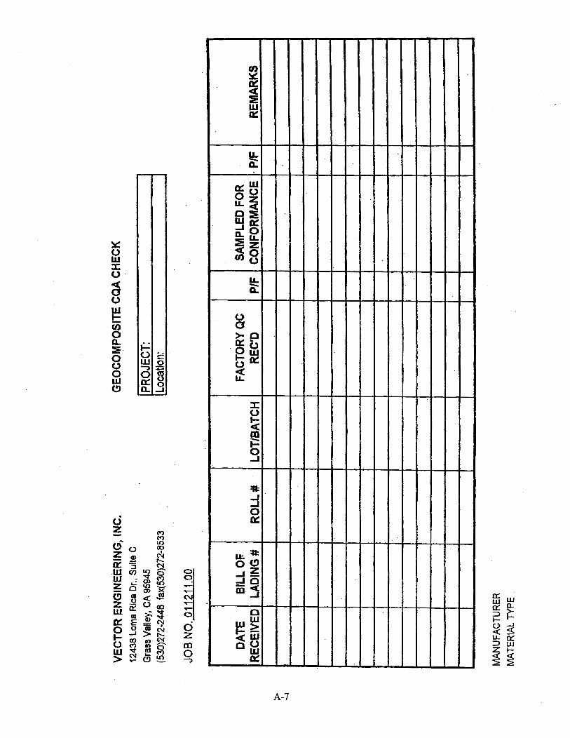
A-7

A-8

6, 0, m a
A-9
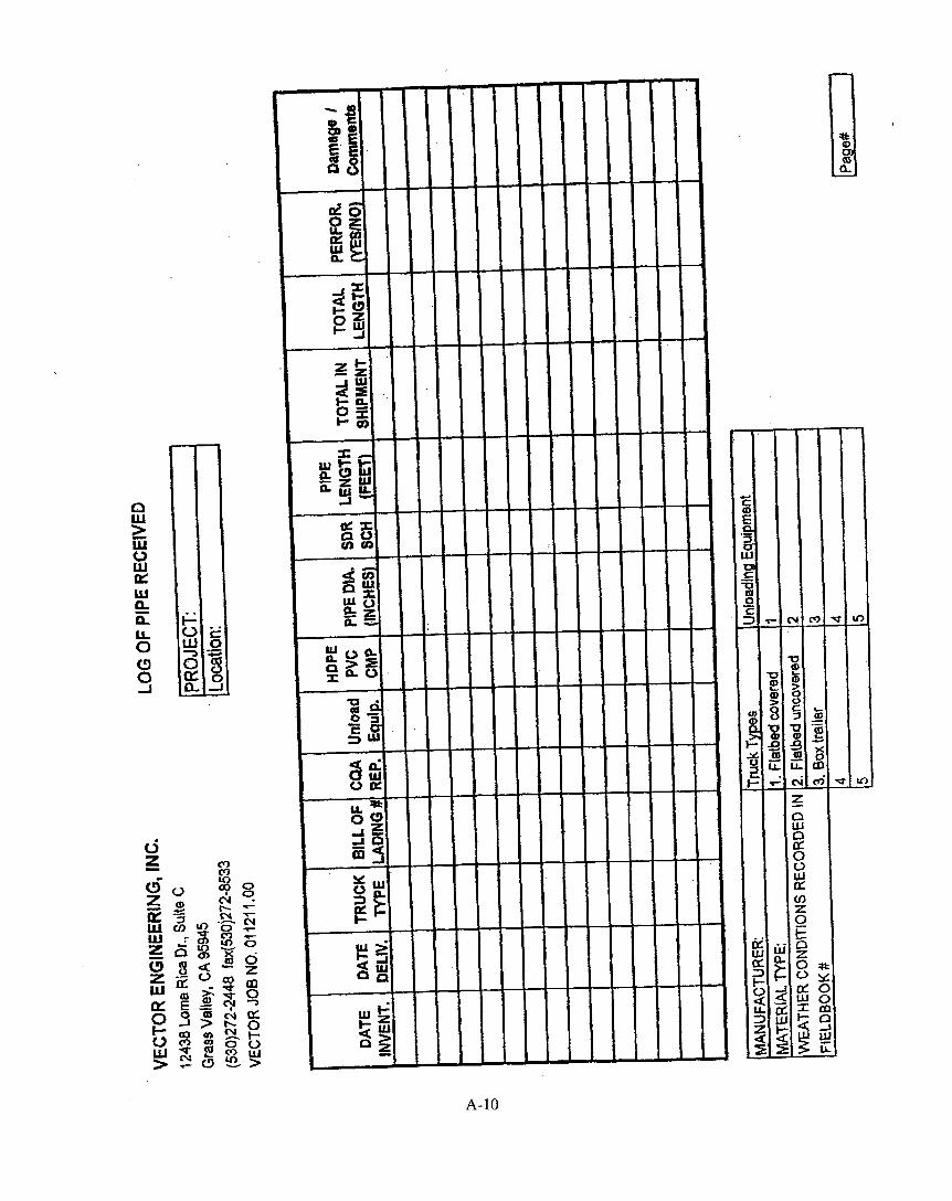
A- 10

A-1 1

I
A-12

A-13

A-14

A-15

u u m u
A-16

A-17

CHAIN OF CUSTODY RECORD
;OMPANY: 'ROJECT W E : E L 0 PHONE:
SEAM
0.0 9.0 9.0 6.0
PROJECT LOCATION: PROJECT NUMBER: FAX RESULTS TO:
Mstedaf IdeaUlPcatlan
1.
2 3.
4.
5.
6.
7.
8.
9.
io.
4.
5.
6.
7.
8.
-..
Released by:
Organ izatian:
Date:
T i e:
. _ _ ._
Received by:
Organization:
Date:
T i e :
Method af Delivery:
A- 18

CHAIN OF CUSTODY RECORD
SAMPLE IDJNUMBER ITESlYNG REWESIED . I
Released by: Received w. Organization: Organ'btian: Date: Date: Time: Time:
Method of Delivery:
A-19

SUMMARY REPORT OF
Project Name: Project No.:
VECTOR
DESTRUCTIVE SEAM TESTS
Material Type: Manufacturer:
Thickness (mils) Shear (ppi) I Peel (ppi) TestNa. SeamNo. TestOate TestAve. Spec. TestAve. Spec. I Test Ave. Spec.
- I I
Reviewed By:
A-20

A-2 1

DESTRUCTIVE
Banded Seam Seam ID Thickness Strength (Shear)
Sample Seam TOP Bottom Load Break No. No. (mil) (ma) bpi) TYQe
I
I I I I I
Average: #DIVIO! #owla! I #DIV/O! { #DIVIO! I J
A
Project Name: Material Type: Project No.: Manufacturer:
Tested By: Checked By:
Sample Location:
Table 1- Shear t 1 I Bonded Seam
Crosshead Speed: Tensile Machine: Grip Dimension:
PROJECT SPECIFICATIONS:
Seam Method: Seam Date:
Machine No.: Welder LO:
SHEAR - PPi
Note: Break Code for Dual W&Qe AD -Adhesion Failure BRK - Break in Sheet SEI- Break in outer edge Qf seam SE2- Break in inner edge of seam through bath sheets AD-BRK - Break in seam after some adheston failure SIP- Separation in Plane
~
PEEL - PPi THICKNESS - mils
Break Cork fw Fusion
AS-WU) -Break UIrcugh the filkt BRK - Break in Sheet SE1- Break in wter edge of seam in the bottom sheet (shear only) SE2- Break In outer edge of seam in the top sheet (shear only) SE3- Break in outer edge of seam in the bottm sheet (peel only) A D W - Break in seam after some adhesion failure
SIP- Separation in Plane
P
A-22

VECTOR
GEOMEMBRANE REPAIR LOG ProJect Name: Material Type:
Project No.:
I I
1 I I
I I
1 I 1
'VT-veUM E S T
SP - SPARK TEST
AL - 41R LANCE RNlEWED BY:
A-23
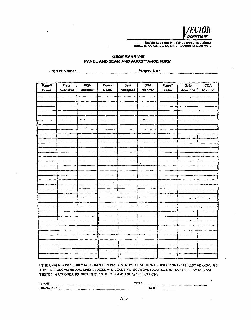
I 1
i I r
I THE UNDERSIGNED. DULY AUTHORIZED REPRESWTATIVE OF VECTOR ENGINEERING 00 HEREBY ACKNOWLED~ THAT THE GEOMEMBRANE UNER PANELS AN0 SEAMS NOTED ABOVE HAVE BEEN INSTALLEO, EXAMINED AND TESTED IN ACCOROANCE WITH THE PROJECT PuWs AN0 SPECJFICATIONS.
NAME TITLE SIGNATURE DATE
A- 24


