Influence of interface roughness in quantum cascade lasers Krivas, K. A.; Winge, David; Franckie, Martin; Wacker, Andreas Published in: Journal of Applied Physics DOI: 10.1063/1.4930572 2015 Document Version: Publisher's PDF, also known as Version of record Link to publication Citation for published version (APA): Krivas, K. A., Winge, D., Franckie, M., & Wacker, A. (2015). Influence of interface roughness in quantum cascade lasers. Journal of Applied Physics, 118(11), [114501]. https://doi.org/10.1063/1.4930572 General rights Copyright and moral rights for the publications made accessible in the public portal are retained by the authors and/or other copyright owners and it is a condition of accessing publications that users recognise and abide by the legal requirements associated with these rights. • Users may download and print one copy of any publication from the public portal for the purpose of private study or research. • You may not further distribute the material or use it for any profit-making activity or commercial gain • You may freely distribute the URL identifying the publication in the public portal Take down policy If you believe that this document breaches copyright please contact us providing details, and we will remove access to the work immediately and investigate your claim.
Transcript
LUND UNIVERSITY
PO Box 117221 00 Lund+46 46-222 00 00
Influence of interface roughness in quantum cascade lasers
Krivas, K. A.; Winge, David; Franckie, Martin; Wacker, Andreas
Published in:Journal of Applied Physics
DOI:10.1063/1.4930572
2015
Document Version:Publisher's PDF, also known as Version of record
Link to publication
Citation for published version (APA):Krivas, K. A., Winge, D., Franckie, M., & Wacker, A. (2015). Influence of interface roughness in quantumcascade lasers. Journal of Applied Physics, 118(11), [114501]. https://doi.org/10.1063/1.4930572
General rightsCopyright and moral rights for the publications made accessible in the public portal are retained by the authorsand/or other copyright owners and it is a condition of accessing publications that users recognise and abide by thelegal requirements associated with these rights.
• Users may download and print one copy of any publication from the public portal for the purpose of private studyor research. • You may not further distribute the material or use it for any profit-making activity or commercial gain • You may freely distribute the URL identifying the publication in the public portalTake down policyIf you believe that this document breaches copyright please contact us providing details, and we will removeaccess to the work immediately and investigate your claim.
Influence of interface roughness in quantum cascade lasersK. A. Krivas, D. O. Winge, M. Franckié, and A. Wacker Citation: Journal of Applied Physics 118, 114501 (2015); doi: 10.1063/1.4930572 View online: http://dx.doi.org/10.1063/1.4930572 View Table of Contents: http://scitation.aip.org/content/aip/journal/jap/118/11?ver=pdfcov Published by the AIP Publishing Articles you may be interested in Leakage current in quantum-cascade lasers through interface roughness scattering Appl. Phys. Lett. 103, 161102 (2013); 10.1063/1.4825229 Importance of interface roughness induced intersubband scattering in mid-infrared quantum cascade lasers Appl. Phys. Lett. 101, 171117 (2012); 10.1063/1.4764516 Influence of the growth temperature on the performances of strain-balanced quantum cascade lasers Appl. Phys. Lett. 98, 091105 (2011); 10.1063/1.3561754 Role of interface roughness in the transport and lasing characteristics of quantum-cascade lasers Appl. Phys. Lett. 94, 091101 (2009); 10.1063/1.3093819 Lasing properties of GaAs/(Al,Ga)As quantum-cascade lasers as a function of injector doping density Appl. Phys. Lett. 82, 671 (2003); 10.1063/1.1541099
[This article is copyrighted as indicated in the article. Reuse of AIP content is subject to the terms at: http://scitation.aip.org/termsconditions. Downloaded to ] IP:
[This article is copyrighted as indicated in the article. Reuse of AIP content is subject to the terms at: http://scitation.aip.org/termsconditions. Downloaded to ] IP:
scattering over the entire range of q values, k tends to
emphasize low momentum transfer. Comparing results when
these parameters are increased separately could give insight
into how important scattering with large momentum transfer
is.
As our non-equilibrium Green’s function model applies
the self-consistent Born approximation in the calculation of
self-energies, multiple-scattering events with a single imper-
fection are neglected. Thus, we cannot reproduce any bound
states due to disorder, which might cause distinct effects of
inhomogeneous broadening. However, such effects only
become of relevance for larger spatial correlation lengths as
discussed in Section IV of Ref. 16. In order to quantify this,
we consider the energy balance for localization at an island
of size k and thickness g. The possible gain in energy at an
island with a locally enlarged well width is about
gDEcjWðziÞj2, where DEc is the conduction band offset and
W(zi) the wave function at the interface. However, the lateral
localization costs an energy larger than �h2=ðmck2Þ, where mc
is the effective mass. Thus, we can exclude any localization
effects as long as
k2g <�h2
mcDEcjW zið Þj2: (3)
For all interfaces considered in this study, the right hand side
is at least 100 nm3 (for the thin barrier in the four-well laser).
Thus, the inequality holds even for the enlarged values
k¼ 15 nm and g¼ 0.3 nm.
An alternative approach to study these issues is the use
of exact eigenstates.7 We could actually show that the line-
shape of our model agrees with such calculations very
well,17 which justifies the Born approximation for interface
roughness.
III. DEVICES STUDIED
In this work, the influence of IFR scattering is investi-
gated using three different terahertz QCL designs, namely, a
two-well,18 a three-well,19 and a four-well20 structure. The
first one employs three states per period for electron trans-
port: an upper lasing state (ULS), a lower lasing state (LLS),
and an injector-extractor state (i-e), as shown in Fig. 2. This
laser operates over a range of frequencies from 2.8 to 4.1
THz, with a maximum reported operating temperature of
125 K. The second (three-well) laser is of resonant phonon
design and therefore has separate states for injection (i) and
extraction (e). The reported lasing frequency is 3.9 THz, and
the reported maximum temperature of operation is 186 K.
The band diagram of this laser is displayed in Fig. 3. The last
investigated QCL employs a scattering assisted design. It
relies on 4 mini-bands distributed over four wells per period.
This laser operates at 3.2 THz at the maximum temperature
of 138 K. The band diagram is shown in Fig. 4.
IV. RESULTS
We investigate the influence of IFR scattering by alter-
ing the interface roughness parameters in the simulations.
These results are then compared to simulations with unal-
tered IFR. As a reference, we use the parameters k¼ 10 nm
and g¼ 0.20 nm. The IFR of the altered interfaces is chosen
to have one of these two parameters increased by 50%. The
interfaces are also assumed to be uncorrelated, so that one
interface distribution does not depend on the others.21 All
simulations are performed for a lattice temperature of 200 K.
It is known that interface roughness can depend on
growth direction.11 Therefore, increasing IFR on every sec-
ond interface would recreate the naturally occurring configu-
ration. The applied bias tilts the potential wells and lets us
distinguish between two different cases: first, when the
altered interfaces are on the lower potential side of the wells
(wb), and second, when the altered interfaces are on the
higher potential side of the wells (bw).
First, we investigate the effect of IFR scattering on the
current density. The results when either half of the interfaces
or all of them are altered are shown in Fig. 5. If the changes
FIG. 1. Different forms of the autocorrelation function, Eq. (2). The full line
is the reference case with g¼ 0.20 nm and k¼ 10.0 nm, the dashed line
shows the case when k is increased by 50% and the dotted-dashed shows the
behavior for the same increase of g.
FIG. 2. Band diagram of the two-well laser18 at 47.5 mV per period with
respect to the growth direction z. The conduction band profile is shown to-
gether with the probability density for the most important subbands at their
respective energies.
114501-2 Krivas et al. J. Appl. Phys. 118, 114501 (2015)
[This article is copyrighted as indicated in the article. Reuse of AIP content is subject to the terms at: http://scitation.aip.org/termsconditions. Downloaded to ] IP:
130.235.187.33 On: Wed, 16 Sep 2015 07:56:03
in current due to a change in IFR are small, we expect that if
we increase the interface roughness on two interfaces simul-
taneously, we obtain the same change in current density as if
we would add the changes in current densities from simula-
tions when these two interfaces have roughness increased
separately. As can be seen from Fig. 5, it is actually possible
to relate the magnitude of the increase in current density to
how well this superposition holds. For instance, the two-well
laser exhibits the lowest increase in current (4%) and shows
the best agreement between simulated relative current and
the sum, while the four-well laser shows the least agreement,
and the increase in current is the highest (21%). The three-
well laser is an intermediate case, having 11% increase in
current density when g is increased by 50% on all interfaces.
It can be seen in Fig. 5 that altering wb interfaces causes
a larger increase in current density than bw interfaces. This
can be understood by the effect that the wavefunctions tend
to shift to the lower potential side of the well when a bias is
applied, as can be seen in Figs. 2–4. This results in higher
wavefunction values at the interfaces at the lower potential
side of a well. Since IFR scattering is proportional to the
product of the wavefunction values at the interfaces, chang-
ing IFR on interfaces with high wavefunction values has a
larger impact on the transport. This observation confirms the
results shown in Ref. 11.
For the two- and three-well lasers, the results of Fig. 5
can be understood using the reasoning above. Here, the (wb)
interfaces dominates the IFR scattering. However, in the
four-well case, the changes due to wb and bw are approxi-
mately the same. This is an effect of the thin barriers, as the
value of the wavefunction of the ground state is actually
lower on the high potential side of the barrier (or, equiva-
lently, on the low potential side of the foregoing well) as
seen in Fig. 4. This is because thin barriers are placed where
the ground state wavefunctions have their maximum, rather
than their minimum, value. However, the thick barriers act
as in the cases of the other two lasers.
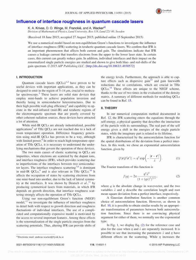
The simulated relative gain spectra compared to unal-
tered IFR, for the respective devices are shown in Fig. 6, and
all devices show an overall decrease in gain as a result of
increasing IFR. However, the magnitude of the effect differs
widely. Again, the two-well laser is the most insensitive to
changes in IFR, with a decrease in gain of 7.2%. The three-
well laser displays a 19.1% reduction, while the gain of the
four-well laser shows a decrease by 50.6% when roughness
parameter g was increased by 50% on all interfaces.
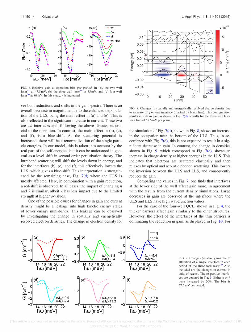
In order to determine in detail the influence of individual
interfaces on the current density and gain, we now change
only one interface at a time and compare these results to the
reference case. These results are shown in Fig. 7 for the
three-well laser. The effects of the changes are twofold; we
FIG. 3. Band diagram of the three-well laser,19 in the same way as Fig. 2
with labels added to distinguish the specific interfaces. The bias is 55 mV
per period.
FIG. 4. Band diagram of the four-well laser20 plotted in the same way as in
Fig. 3, at a bias of 80 mV per period.
FIG. 5. Results of current density sim-
ulations. (a) Two-well laser,18 (b)
three-well laser,19 and (c) four-well
laser.20 The parameter g is increased
by 50% with respect to the reference
calculation (ref) for different sets of
interfaces.
114501-3 Krivas et al. J. Appl. Phys. 118, 114501 (2015)
[This article is copyrighted as indicated in the article. Reuse of AIP content is subject to the terms at: http://scitation.aip.org/termsconditions. Downloaded to ] IP:
130.235.187.33 On: Wed, 16 Sep 2015 07:56:03
see both reductions and shifts in the gain spectra. There is an
overall decrease in magnitude due to the enhanced depopula-
tion of the ULS, being the main effect in (a) and (e). This is
also reflected in the significant increase in current. These two
are wb interfaces and, following the above discussion, cru-
cial to the operation. In contrast, the main effect in (b), (c),
and (f), is a blue-shift. As the scattering potential is
increased, there will be a renormalization of the single parti-
cle energies. In our model, this is taken into account by the
real part of the self energies, but it can be understood in gen-
eral as a level shift in second order perturbation theory. The
intraband scattering will shift the levels down in energy, and
for the interfaces (b), (c), and (f), this effectively lowers the
LLS, which gives a blue-shift. This interpretation is strength-
ened by the remaining case, Fig. 7(d) where the ULS is
mostly affected. Here, in combination with a gain reduction,
a red-shift is observed. In all cases, the impact of changing gand k is similar, albeit k has less impact due to the limited
strength at higher q-values.
One of the possible causes for changes in gain and current
density might be a leakage into high kinetic energy states
of lower energy mini-bands. This leakage can be observed
by investigating the change in spatially and energetically
resolved electron densities. The change in electron density for
the simulation of Fig. 7(d), shown in Fig. 8, shows an increase
in the occupation near the bottom of the ULS. Thus, in ac-
cordance with Fig. 7(d), this is not expected to result in a sig-
nificant decrease in gain. In contrast, the change in densities
shown in Fig. 9, which correspond to Fig. 7(e), shows an
increase in charge density at higher energies in the LLS. This
indicates that electrons are scattered elastically and then
relaxes by optical and acoustic phonon scattering. This lowers
the inversion between the ULS and LLS, and consequently
reduces the gain.
Comparing the values in Fig. 7, one finds that interfaces
at the lower side of the well affect gain more, in agreement
with the results from the current density simulations. Large
decreases in gain are observed at the interfaces where the
ULS and LLS have high wavefunction values.
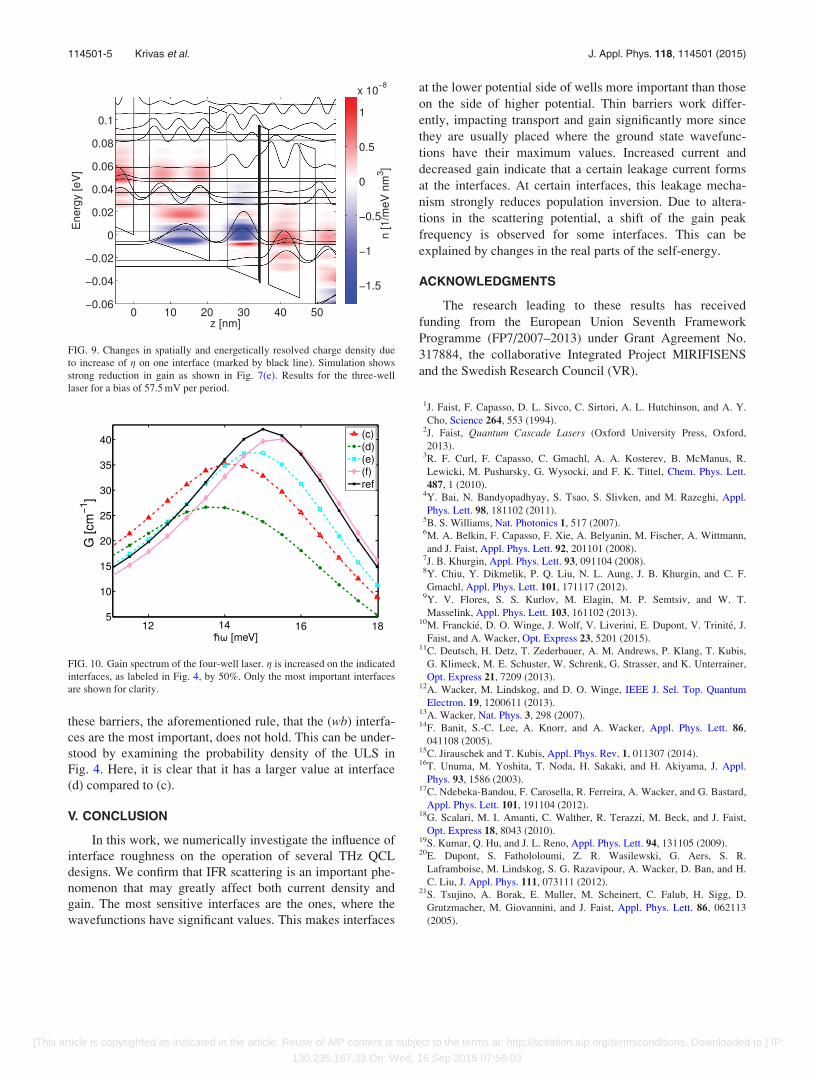
For the case of the four-well QCL, shown in Fig. 4, the
thicker barriers affect gain similarly to the other structures.
However, the effect of the interfaces of the thin barriers is
dominating the reduction in gain, as displayed in Fig. 10. For
FIG. 6. Relative gain at operation bias per period. In (a), the two-well
laser18 at 47.5 mV, (b) the three-well laser19 at 55 mV, and (c) four-well
laser20 at 80 mV. In this study, g is increased.
FIG. 7. Changes (relative gain) due to
alteration of a single interface in each
period of the three-well laser.19 Also
included are the changes in current in
units of A/cm2. The respective interfa-
ces are denoted in Fig. 3. Either g or kwere increased by 50%. The bias is
57.5 mV per period.
FIG. 8. Changes in spatially and energetically resolved charge density due
to increase of g on one interface (marked by black line). This configuration
results in shift in gain as shown in Fig. 7(d). Results for the three-well laser
for a bias of 57.5 mV per period.
114501-4 Krivas et al. J. Appl. Phys. 118, 114501 (2015)
[This article is copyrighted as indicated in the article. Reuse of AIP content is subject to the terms at: http://scitation.aip.org/termsconditions. Downloaded to ] IP:
130.235.187.33 On: Wed, 16 Sep 2015 07:56:03
these barriers, the aforementioned rule, that the (wb) interfa-
ces are the most important, does not hold. This can be under-
stood by examining the probability density of the ULS in
Fig. 4. Here, it is clear that it has a larger value at interface
(d) compared to (c).
V. CONCLUSION
In this work, we numerically investigate the influence of
interface roughness on the operation of several THz QCL
designs. We confirm that IFR scattering is an important phe-
nomenon that may greatly affect both current density and
gain. The most sensitive interfaces are the ones, where the
wavefunctions have significant values. This makes interfaces
at the lower potential side of wells more important than those
on the side of higher potential. Thin barriers work differ-
ently, impacting transport and gain significantly more since
they are usually placed where the ground state wavefunc-
tions have their maximum values. Increased current and
decreased gain indicate that a certain leakage current forms
at the interfaces. At certain interfaces, this leakage mecha-
nism strongly reduces population inversion. Due to altera-
tions in the scattering potential, a shift of the gain peak
frequency is observed for some interfaces. This can be
explained by changes in the real parts of the self-energy.
ACKNOWLEDGMENTS
The research leading to these results has received
funding from the European Union Seventh Framework
Programme (FP7/2007–2013) under Grant Agreement No.
317884, the collaborative Integrated Project MIRIFISENS
and the Swedish Research Council (VR).
1J. Faist, F. Capasso, D. L. Sivco, C. Sirtori, A. L. Hutchinson, and A. Y.
2013).3R. F. Curl, F. Capasso, C. Gmachl, A. A. Kosterev, B. McManus, R.
Lewicki, M. Pusharsky, G. Wysocki, and F. K. Tittel, Chem. Phys. Lett.
487, 1 (2010).4Y. Bai, N. Bandyopadhyay, S. Tsao, S. Slivken, and M. Razeghi, Appl.
Phys. Lett. 98, 181102 (2011).5B. S. Williams, Nat. Photonics 1, 517 (2007).6M. A. Belkin, F. Capasso, F. Xie, A. Belyanin, M. Fischer, A. Wittmann,
and J. Faist, Appl. Phys. Lett. 92, 201101 (2008).7J. B. Khurgin, Appl. Phys. Lett. 93, 091104 (2008).8Y. Chiu, Y. Dikmelik, P. Q. Liu, N. L. Aung, J. B. Khurgin, and C. F.
Gmachl, Appl. Phys. Lett. 101, 171117 (2012).9Y. V. Flores, S. S. Kurlov, M. Elagin, M. P. Semtsiv, and W. T.
Masselink, Appl. Phys. Lett. 103, 161102 (2013).10M. Francki�e, D. O. Winge, J. Wolf, V. Liverini, E. Dupont, V. Trinit�e, J.
Faist, and A. Wacker, Opt. Express 23, 5201 (2015).11C. Deutsch, H. Detz, T. Zederbauer, A. M. Andrews, P. Klang, T. Kubis,
G. Klimeck, M. E. Schuster, W. Schrenk, G. Strasser, and K. Unterrainer,
Opt. Express 21, 7209 (2013).12A. Wacker, M. Lindskog, and D. O. Winge, IEEE J. Sel. Top. Quantum
Electron. 19, 1200611 (2013).13A. Wacker, Nat. Phys. 3, 298 (2007).14F. Banit, S.-C. Lee, A. Knorr, and A. Wacker, Appl. Phys. Lett. 86,
041108 (2005).15C. Jirauschek and T. Kubis, Appl. Phys. Rev. 1, 011307 (2014).16T. Unuma, M. Yoshita, T. Noda, H. Sakaki, and H. Akiyama, J. Appl.
Phys. 93, 1586 (2003).17C. Ndebeka-Bandou, F. Carosella, R. Ferreira, A. Wacker, and G. Bastard,
Appl. Phys. Lett. 101, 191104 (2012).18G. Scalari, M. I. Amanti, C. Walther, R. Terazzi, M. Beck, and J. Faist,
Opt. Express 18, 8043 (2010).19S. Kumar, Q. Hu, and J. L. Reno, Appl. Phys. Lett. 94, 131105 (2009).20E. Dupont, S. Fathololoumi, Z. R. Wasilewski, G. Aers, S. R.
Laframboise, M. Lindskog, S. G. Razavipour, A. Wacker, D. Ban, and H.
C. Liu, J. Appl. Phys. 111, 073111 (2012).21S. Tsujino, A. Borak, E. Muller, M. Scheinert, C. Falub, H. Sigg, D.
Grutzmacher, M. Giovannini, and J. Faist, Appl. Phys. Lett. 86, 062113
(2005).
FIG. 9. Changes in spatially and energetically resolved charge density due
to increase of g on one interface (marked by black line). Simulation shows
strong reduction in gain as shown in Fig. 7(e). Results for the three-well
laser for a bias of 57.5 mV per period.
FIG. 10. Gain spectrum of the four-well laser. g is increased on the indicated
interfaces, as labeled in Fig. 4, by 50%. Only the most important interfaces
are shown for clarity.
114501-5 Krivas et al. J. Appl. Phys. 118, 114501 (2015)
[This article is copyrighted as indicated in the article. Reuse of AIP content is subject to the terms at: http://scitation.aip.org/termsconditions. Downloaded to ] IP: