1 1 Information Unlimited Inc Marx Generator Series Impulse Generators Operational Manual model #IU1080 3200 Joules at 800,000 Kilovolts These products are fully described on our web site at www.amazing1.com INTRODUCTION Information Unlimited is a company dealing with education, research, engineering design, development and manufacturing. The company was established in1975 and holds many patents. Members of our staff have written books and technical articles appearing in leading technological magazines. Our main laboratory is in southern New Hampshire and was featured on television in September of 2003. Our offices are located in New Hampshire, Florida and Kowloon HK. We also manufacture spark gaps, rail gaps, pulse and high voltage transformers, triggers and a host of other HV Components. SPECIAL NOTE ON RENTED EQUIPMENT It is very important to save all crates, covers and packing materials as the item must be returned fully operational and undamaged for you to receive back the funds held for the rental period.. WARNING
Transcript
1
1
Information Unlimited Inc Marx Generator Series
Impulse Generators
Operational Manual model #IU1080 3200 Joules at 800,000 Kilovolts
These products are fully described on our web site at www.amazing1.com
INTRODUCTION
Information Unlimited is a company dealing with education, research, engineering design,
development and manufacturing. The company was established in1975 and holds many patents.
Members of our staff have written books and technical articles appearing in leading technological
magazines. Our main laboratory is in southern New Hampshire and was featured on television in
September of 2003. Our offices are located in New Hampshire, Florida and Kowloon HK. We
also manufacture spark gaps, rail gaps, pulse and high voltage transformers, triggers and a host
of other HV Components.
SPECIAL NOTE ON RENTED EQUIPMENT
It is very important to save all crates, covers and packing materials as the item must be returned
fully operational and undamaged for you to receive back the funds held for the rental period..
WARNING
2
2
Please note this system must be operated by only those fully experienced and aware of all high
voltage hazards and with full knowledge of high voltage and its safety requirements. This
equipment can only be purchased upon receipt of our Hazardous Equipment signed and dated by
the user.
WARNING
These devices as sold will require proper housings, safety interlocks, fusing, labeling, qualified
training and certain safety compliances dependent on the intended application.
The purchaser will not to hold the seller responsible in any way for injuries resulting from proper
or improper use of this equipment. Please note that this system can store over 60 times the
energy to kill a normal human being-obviously extreme caution is required..
SPECIFICATIONS: RISE TIME.…………………………………………. Typically < 20 nano second
PULSE WIDTH……………………………………… Typically < l00 nano second
ENERGY……………………………………………... 3200 Joules
PULSE REPETITION RATE…………………………2 per minute
TYPICAL OUTPUT……………………………………600Kv Pulsed
MAX. OUTPUT PULSE……………………………….800Kv Pulses
GENERATOR IMPEDANCE…………………………< 100 Ohms
PEAK CURRENT………………………………………5KA Maximum
PEAK PULSE POWER………………………………..4 Gigawatts.
ERECTED CAPACITANCE…………………………..15nf
STAGE CAPACITANCE……………………………….150nf
NUMBER OF STAGES…………………………………10
3
3
BASIC DESCRIPTION
All the models of Impulse Generators are fully functional with no other equipment needed. They
have an input voltage of 230volts / 50Hz / 60IIz that can be smoothly varied by a built in variable
voltage transformer. Output impulse voltage is dependent on the spark gap selection & firing
system. A manual button as well as a +5Volts command Input is also provided to fire the
generator. This can also be used to synchronize it with another scientific event which will give a +
5 volts output pulse. The pulse required shall be approximately of the order of 3 to 5 us seconds
width and a voltage of 5 to 7 volts Amplitude.
All the Impulse Generators are made on the basic principle of parallel charge and series
discharge of very low inductance capacitors through suitable spark gap system that can handle
these type of peak currents and electrical stresses. You may find a more detailed description on
our web site at www.amazing1.com.
SYSTEM DESCRIPTION
The system consists of three basic sections (see photo 9):
The main discharge section consists of two separate modules (designated A&B) along with the
movable base section with heavy duty casters. The assembly of this section will require several
strong individuals to lift and place module B onto the movable base and then module A onto
module B. This modular approach facilitates transport and crating. (See photo 6,7,8)
The charging module (designated D) supplies the charging voltage to the main discharge
section. This section uses a core and coil 10,000 volt transformer connected to an eight stage
voltage multiplier of diodes and capacitors and will produce over 100 Kv open circuit.
The control console (designated C) is where main system power is controlled, voltage and
charge energy, triggering mode selection along with all necessary control functions
4
4
SITE ASSEMBLY Select the area of operation and note proper clearance and proximity to sensitive electronic
equipment. Remove the unit from the 5 packing crates and check for any physical damage. The
crates are marked. Position the individual sections as shown in photo 1.
CONNECTIONS
The three sections are inter-connectd by several cables and heavy grounding leads. All are
coded with a letter corresponding to their respective mating points to the individual sections.
1. Connect the heavy green grounding leads that are coded E3 MAIN to E2
CHARGER. and E2 CHARGER to E1 CONTROL BOX
2. Connect the coaxial cables that are coded T1 CONTROL BOX to T2 CHARGER and
T3 CHARGER to T4 MAIN
3. Connect the heavy multi conductor cables that are coded C3 CHARGER to C1
CONTROL BOX and L1 to LINE POWER CABLE
4. System input line power is 220 volts at 50 to 60 Hz. You may have to select and wire
in a plug that mates to your line power receptables. Line current requirements are
less than 5 amps.
5. Connect a heavy ground lead (not supplied) to the heavy grounding screw on the
charging module. This lead should go to a dedicated and verified ground.
6. Connect up the flat copper discharge bars as shown in photos 2 and 3
7. Connect the orange high voltage charging cable from the MAIN section to the screw
in plastic jack on the CHARGER.
command via an input jack or a manual button now initiating the first stage which discharges
automatically.
5
5
OPERATION
Verify all capacitors are fully discharged by shorting each individual one with a safety shorting
stick. (See photo 3,4)
Check if all Spark Gap Assemblies are facing each other and not twisted, If twisted, make it
straight facing each other. Ensure the Gap between both of them is 38mm . Keep the Lowest
Gap Less by 5mm. So if all are adjusted at 38mm adjust this at 33mm, (Lowest).
It is suggested to wear hearing protection for the remaining test..
Set the discharge gap to approx 300 mm. You may increase to 650mm for maximum discharge
once familiar with operating etc.
Take care that the Voltage Control is at Zero.
Switch on the Power Switch.
Slowly raise the voltage by turning the knob clockwise gradually
Go to l0KvDC and in steps of 5KvDC. Keep raising the voltage and at approximately 50 to
55KvDC. An automatic self discharge will eventually occur with a very loud shock wave.
Note the operating voltage on the Kv Meter (This is auto self fire voltage) and set the Marx
Generator at 4 to 5Kv below this voltage level. Now press the Manual Switch to see the
Discharge again* If vou want the discharge to function in synchronization with some other event
or activity you may apply a 5 to 9 volt pulse to the BNC connector.
Note pre-firing may occur due to difference in temperature as well as sea level problems. It may
take 8 to 10 Shots making adjustments and allowing the spark gap air medium to settle down for
consistent firing at a preset required voltage. It is best suited to operate the Marx at max, 600Kv
to ensure Long Life.
6
6
All the Spark Gaps are factory set and if adjustment is required, you will have to obtain a drill bit
to reset the gaps. Settings can range from 15 to 25mm Max between the Sphere Electrodes.
See below chart for optional settings:
5mm…………………….12 kv per stage for 120 kv output between discharge electrodes.
10mm…………………….30 kv per stage for 300 kv output between discharge electrodes.
15mm…………………….43 kv per stage for 430 kv output between discharge electrodes.
20mm…………………….55 kv per stage for 550 kv output between discharge electrodes.
25mm…………………….70 kv per stage for 700 kv output between discharge electrodes.
The Generator is made in Open Transparent Construction and hence all parts are at High
Voltage.
NOTES:
1. Always operate the Marx Generator with the bottom trigger starting gap of 2 to 5mm less than
the other nine spark gaps.
2. Manually triggering the system using the manual or external +5 Volts pulse will require the
voltage being set to 5Kv below self breakdown voltage.
3. Always respect the generator as it can kill you. Always remove all power and individually
discharge each capacitor starting from the bottom of the system before handling or making
adjustments. Use a suitably insulated probe. See photo 4
4 Keep a distance of at least 3 meters from the machine when it is operating and wear hearing
protection.
5 Always check the generator voltage as indicated on the panel meter
6 Always provide a verified ground connection for the Marx Generator as all non circulating and
radiating energy must go to ground.
7 Never operate the system in wet or high moisture conditions.
7
7
8 Keep all personal and equipment clear of the discharge area by at least 3 meters.
9 The Marx can radiate damaging amounts of pulse energy. This property requires to keeping all
other measuring and support systems totally shielded and grounded
10 Don't keep explosives, fireworks, dry materials such as hay, sawdust, compressed gas bottles
near the generator when it fires.
11 Items like dry silk, dry hay, radio isotopes, fireworks, mobile phones or other sensitive
communication equipment must be kept at least l0 meters away from the Marx Generator while
operating.
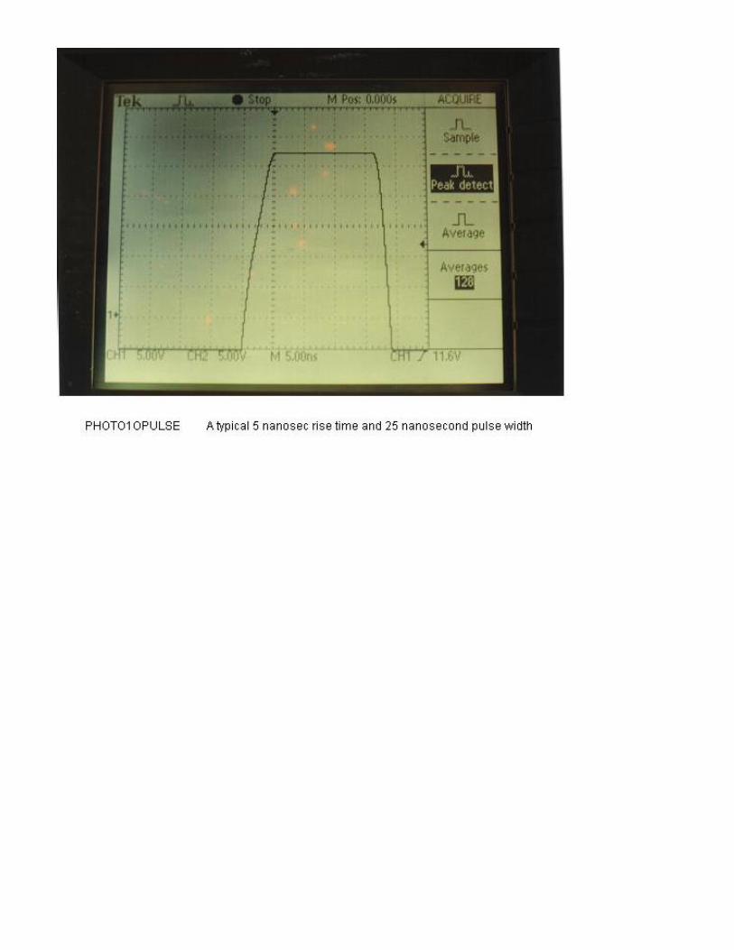
Typical discharge wave forms are shown in photo 10,11