60
SI Range Installation and Maintenance Instructions PUB021-003-00 Date of issue 10/10
SI RangeInstallation andMaintenanceInstructions
PUB021-003-00Date of issue 10/10

THE ROTORK Fluid SySTEmS Si ACTuATOR – A REliABlE SOluTiON FOR ElECTRiC FAilSAFE ANd mOdulATiNG VAlVE CONTROl THAT yOu CAN COmmiSSiON ANd iNTERROGATE WiTHOuT REmOViNG ElECTRiCAl COVERS.
Using the supplied infra-red Setting Tool to access the actuator set-up procedures, “point and shoot” setting of position limits, and all other control and indication functions can be made safely, quickly and conveniently, even in hazardous locations.
Standard diagnostics information about the control system, valve and actuator status in the form of display icons and help screens. Instantaneous internal hydraulic pressure and valve position are displayed on the integral indication display.
Visit our web site at www.rotork.com for more information on the Rotork Fluid Systems SI and other Rotork actuator ranges.
This manual provides instruction on:
* Electrical (local and remote) and optional manual operation.
* Preparation and installation of the actuator onto the valve.
* Subsequent commissioning and adjustment of the Primary Settings for correct valve operation.
* Commissioning and adjustment of the Secondary Settings to suit site-specific control and indication requirements.
* Maintenance – Troubleshooting.

1
Section Page
1 Health and Safety 2
2 Storage 3
3 Operating your Si Actuator 4 3.1 Electrical Operation 4 3.2 Display – Local Indication 4 3.3 Display – Alarm Indication 5
4 Optional manual Operation 6
5 mounting the Actuator 7 5.1 Lifting 7 5.2 Mounting Orientation – 8 SI-Q Actuators 5.3 Mounting SI-Q to Valve 8 5.4 Mechanical Travel Adjustment 8 Q31-Q41 5.5 Mechanical Travel Adjustment 9 Q51-Q80 5.6 Mechanical Travel Adjustment 9 Q110-130 5.7 Mounting Orientation–SI-L Actuators 10 5.8 Mounting SI-L to Valve 11
6 Cable Connections 12 6.1 Earth/Ground Connections 12 6.2 Removing Terminal Cover 12
6.3 Cable Entry 12 6.4 Connecting to Terminals 13 6.5 Replacing Terminal Cover 13 6.6 Prior to Commissioning 13
7 Commissioning Overview 14 7.1 Procedure Overview 14 7.2 The Rotork Setting Tool Pro 15 7.3 The Actuator Display – 16 Setting/Checking Mode 7.4 Entering the Actuator 16 Setting Procedure 7.5 Exit Setting Mode 17 7.6 Setting Mode and Password 17 7.7 Change Password (PE) 17 7.8 Checking Mode 17 7.9 Crossroad Branch [Cr] 17
8 Commissioning – Primary Functions 18 8.1 Configuration Menu 20 Close Limit 20 Open Limit 21 8.2 Remote Control Menu 22 Remote Select 22 Configure Local 23 Remote Priority 23 ESD Action 24
ESD Local Stop Override 24 ESD Contact Type 25 Analogue Signal Failure Action 25
9 Commissioning – Secondary Functions 26 9.1 Settings Menu 28 9.2 Controller Set-up Menu 32 9.3 Interrupter Timer 42 9.4 Help Screens 45
10 maintenance, monitoring and Troubleshooting 51 10.1 Maintenance, Monitoring 51 and Troubleshooting 10.2 Environmental 52
11 Weights and measures 53 11.1 Weights and Measures 53 11.2 Actuator Nameplate 54
12 Hazardous Area Approvals 55
13 Special Conditions of Safe use 56
CONTENTS
Section Page
Section Page
2
This manual is produced to enable a competent user to install, operate, adjust and inspect Rotork Fluid Systems SI range of valve actuators.
The electrical installation, maintenance and use of these actuators should be carried out in accordance with the National Legislation and Statutory Provisions relating to the safe use of this equipment, applicable to the site of installation.
For the UK: Electricity at Work Regulations 1989 and the guidance given in the applicable edition of IEE Wiring Regulations should be applied. Also, the user should be fully aware of his duties under the Health and Safety Act 1974.
For the USA: NFPA70, National Electrical Code® is applicable.
The mechanical installation should be carried out as outlined in the manual and also in accordance with relevant standards such as the British Standard Code of Practice. If the actuator has nameplates indicating that it is suitable for installation in hazardous gas areas, the actuator is suitable for use in Zone 1 and Zone 2 explosive atmospheres only. It should not be installed in
atmospheres where gases are present with an ignition temperature less than 135 °C (T4), unless suitability for lower ignition temperatures has been indicated on the actuator nameplate.
Any test instruments applied to the actuator should be of equivalent certification. The electrical installation, maintenance and the use of the actuator should be carried out in accordance with the code of practice relevant for that particular hazardous gas area certification.
No inspection or repair should be undertaken unless it conforms to the specific hazardous gas area certification requirements. Under no circumstances should any modification or alteration be carried out on the actuator as this could invalidate the conditions under which its certification was granted.
Access to live electrical conductors is forbidden in hazardous areas unless this is done under a special permit to work. Otherwise all power should be isolated and the actuator moved to a non-hazardous area for service or repair.
Any service or maintenance must only be undertaken by a approved Rotork Fluid Systems technician.
Work undertaken must be carried out in accordance with instructions in this manual. Any person working on this equipment should be familiar with their responsibilities under any statutory provisions relating to health and safety in their workplace.
The user must ensure that the operating environment and any materials surrounding the actuator cannot lead to a reduction in the safe use of, or the protection afforded by, the actuator. Where appropriate the user must ensure the actuator is suitably protected against its operating environment.
Should further information and guidance relating to the safe use of the Rotork Fluid Systems SI range of actuators be required, it will be provided on request.
Products manufactured by Rotork Fluid Systems do not present a hazard to health under normal conditions of storage, distribution and use, provided that good industrial and hygiene procedures are followed.
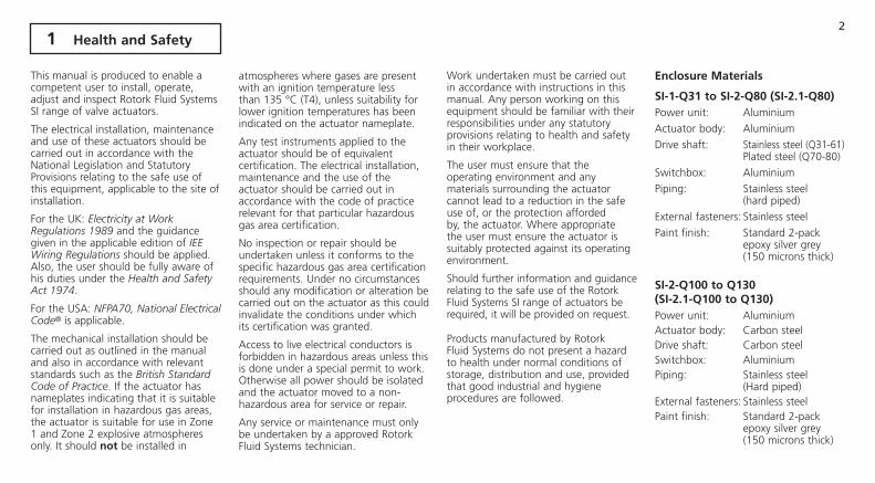
Enclosure materials
Si-1-Q31 to Si-2-Q80 (Si-2.1-Q80)Power unit: Aluminium
Actuator body: Aluminium
Drive shaft: Stainless steel (Q31-61) Plated steel (Q70-80)
Switchbox: Aluminium
Piping: Stainless steel (hard piped)
External fasteners: Stainless steel
Paint finish: Standard 2-pack epoxy silver grey (150 microns thick)
Si-2-Q100 to Q130 (Si-2.1-Q100 to Q130)Power unit: AluminiumActuator body: Carbon steelDrive shaft: Carbon steelSwitchbox: AluminiumPiping: Stainless steel (Hard piped)External fasteners: Stainless steelPaint finish: Standard 2-pack epoxy silver grey (150 microns thick)
1 Health and Safety

3
Si-1-l and Si-2-l (Si-2.1-l) All sizes
Power unit: AluminiumActuator body: Steel
Piston rod: Stainless steel
Piping: Stainless steel (Hard piped)
External fasteners: Stainless steel
Paint finish: Standard 2-pack epoxy silver grey (150 microns thick)
WARNiNG:
Control and indication Where the actuator build allows remote control and indication supplies higher than 150 VAC but below 300 VAC (refer to actuator wiring diagram) the actuator installation altitude must be restricted to less than 2000m as defined by BS EN 61010 or IEC 61010 (safety requirements for electrical equipment for measurement, control and laboratory use).
WARNiNG:Hydraulic Fluid SI actuators are filled with hydraulic fluid. See actuator data label for type of oil supplied.
Should there be a requirement to change the fluid, then the appropriate protective clothing including gloves and safety glasses must be worn. Used hydraulic fluid must be disposed of safely (see environmental section).
Note the Material Safety specification covering the type of hydraulic oil supplied by Rotork Fluid Systems for use within the supplied power units are available on request.
WARNiNG:Compressed SpringsAll springs within the SI range of actuators are pre-compressed. Springs must not be removed from the actuator.
WARNiNG:
Operating by HandWith respect to optional handwheel operation of Rotork Fluid Systems actuators, see warnings in section 4.
If your actuator cannot be installed immediately then store it in a dry place until you are ready to connect incoming cables.
If the actuator is to be installed but not immediately cabled, it is recommended that any plastic cable entry transit plugs be replaced with a suitable metal plug. The double-sealed construction of the terminal compartment will preserve internal electrical components perfectly if left undisturbed.
It is not necessary to remove the electrical compartment covers in order to commission the SI actuator. Rotork Fluid Systems will not accept responsibility for deterioration caused on site by the removal of covers.
Every Rotork Fluid Systems actuator has been fully tested before leaving the factory to give years of trouble free operation, providing it is correctly commissioned, installed and sealed.
Do not store in temperatures beyond the normal operating range as stated on data label.
2 Storage

4
3.1 Electrical Operation
Check that power supply voltage is the same as that stamped on the actuator nameplate. Switch on power supply. It is not necessary to check phase rotation (on 3-phase units).
Selecting local/Stop/Remote Operation
The red selector enables either Local or Remote control. It can be locked in either position using a padlock with a maximum 6.5mm shackle.
When the selector is locked in the Local or Remote positions the Stop facility is still available. The selector can also be locked in the Stop position to prevent electrical operation by Local or Remote control.
local Control
With the red selector positioned at Local (anti-clockwise) the adjacent black knob can be turned to select Open or Close. For Stop, turn red knob clockwise.
Fig. 3.1.
Remote Control
Rotate the red selector to the Remote position (clockwise), this gives Remote control only for Open and Close but local Stop can still be used by turning the red knob anti-clockwise.
3.2 display–local indication
Fig. 3.2. The Actuator Display
The display consists of the following:
1. Red – position indication lamp
2. Yellow – position indication lamp
3. Green – position indication lamp
4. Liquid crystal display screen (LCD)
5. Infra-red sensors
On power up the actuator’s liquid crystal display screen is back-lit with a soft amber light. One of the position indicator lamps will be on and the display screen will also show internal hydraulic pressure and either percent open or an end-of-travel symbol. (See figures 3.3., 3.4. and 3.5.)
As standard, a red lamp signifies valve open, yellow intermediate, and green closed. Open and closed colour functions can be reversed. (See section 9 for function "Ld".)
Closed
Green indicator, internal hydraulic pressure and valve closed symbol displayed.
Fig. 3.3. 0%, Fully Closed.
143
2
5
3 Operating your Si Actuator

5
mid-Travel
Yellow indicator, internal hydraulic pressure and percentage valve open value displayed.
Fig. 3.4. 30% of maximum rated pressure, 25% Open.
Open
Red indicator, internal hydraulic pressure and valve open symbol displayed.
Fig. 3.5. 40% of maximum rated pressure, Fully Open.
When the main power supply is off the liquid crystal display is blank.
3.3 Alarm indication
The SI display incorporates an actuator alarm indication in the form of a display icon located in the top portion of the actuator display.
Fig. 3.6.
When an active actuator alarm is present the alarm icon will be displayed. Also, the display will cycle between pressure/valve position and a fault indication code. For example, figure 3.6 indicates a fault – Over pressure in mid- travel, valve 30% open. (See section 9.3.)
Standard help screens are also available to assist in determining the actuator operational and alarm status. (See section 9.5.)
3 Operating your Si Actuator continued
6
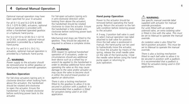
Optional manual operation may have been specified for your SI actuator.
For all SI-1-Q and SI-2-Q70 & Q80 (SI-2.1-Q70 & Q80), actuators, optional manual operation is provided with either a handwheel operated gearbox or a hydraulic hand pump.
For SI-2-Q110 to Q130 (SI-2.1-Q110 to Q130), actuators, optional manual operation is provided by a hydraulic hand pump.
For all SI-1-L and SI-2-L (SI-2.1L), actuators, optional manual operation is provided by a hydraulic hand pump.
WARNiNG:Power supply to the actuator should be removed prior to either gearbox or hand pump manual override operation.
Gearbox Operation
For fail-close actuators (spring acts in clockwise direction when looking from above the actuator), the handwheel should be rotated anti-clockwise to open the actuator. Ensure the handwheel is fully rotated clockwise before switching power back to the actuator.
For fail-open actuators (spring acts in anti-clockwise direction when looking from above the actuator), the handwheel should be rotated clockwise to close the actuator. Ensure the handwheel is fully rotated anti-clockwise before switching power back to the actuator.
Mechanical end stops are fitted to the gearbox. They should be adjusted as required to achieve a complete stroke.
WARNiNG:With respect to optional handwheel operation of SI actuators, under no circumstances should any additional lever device such as a wheel key or wrench be applied to the handwheel in order to develop additional force when operating the valve as this may cause damage to the valve and/or actuator or, may cause the valve to become stuck in either the end-of-travel position or against an obstruction.
There is also a locking mechanism fitted to the gearbox to allow it to be secured in position with a padlock. It is recommended that a padlock is fitted for actuators being used in an ESD application.
Hand pump Operation
Power to the actuator should be removed before operating the hand pump. Return the actuator to the fail-safe condition before restoring power to the actuator.
A 3-way, 2-position ball valve is used to select manual operation (see label attached to ball valve for position). Once the ball valve is positioned in manual, the hand pump can be used to hydraulically move the actuator. To move the actuator by means of the spring, release the small needle valve on the side of the hand pump. Close the needle valve before using the hand pump again or returning to auto operation.
WARNiNG:See specific manual override label supplied with actuator for manual override procedure.For units fitted with an external solenoid valve, an extra isolating valve is fitted in line with the valve. This must be set to Manual to operate the manual override.
An isolation valve is also fitted for fail-in-position actuators. This must be set to Manual to operate the manual override.
There is also a locking mechanism fitted to each ball valve to allow it to be secured in position with a padlock. It is recommended that a padlock is fitted for actuators being used in ESD applications.
4 Optional manual Operation

7
5.1 lifting
Ensure the valve is secure before fitting the actuator as the combination may be top heavy and therefore unstable.
SI-1-Q31 to SI-2-Q80 (SI-2.1-Q80), quarter- turn actuators should be lifted between the power unit and the mounting bracket. (See figure 5.1.)
WARNiNG:Do not lift the actuator from the end caps.
SI-2-Q100 to Q130 (SI-2.1-Q100 to Q130), actuators should be lifted using the two lifting eyes, located on the spring can and cylinder end flange.
SI-1-L and SI-2-L (SI-2.1L), actuators should be lifted using the base plate beneath the cylinder and the power unit (See figure 5.2.)
Under no circumstances should hydraulic piping or electrical cabling be used for lifting purposes.
If it is necessary to lift the actuator using mechanical lifting equipment, certified slings should be attached as indicated in figure 5.1 for SI-Q actuators and figure 5.2 for SI-L actuators.
At all times trained and experienced personnel should ensure safe lifting, particularly when mounting actuators.
WARNiNG:The actuator should be fully supported until complete valve shaft engagement is achieved and the actuator is secured to the valve mounting flange.
Actuator to valve fixing must conform to material specification ISO Class 8.8, yield strength 628 N/sq mm.
WARNiNG:Do not lift the actuator and valve combination via the actuator. Always lift the valve/actuator assembly via the valve.
Each assembly must be assessed on an individual basis for safe lifting.
See SI-Q and SI-L data sheet for actuator base and mounting dimensions.
Fig. 5.1. Fig. 5.2.
5 mounting the Actuator
8
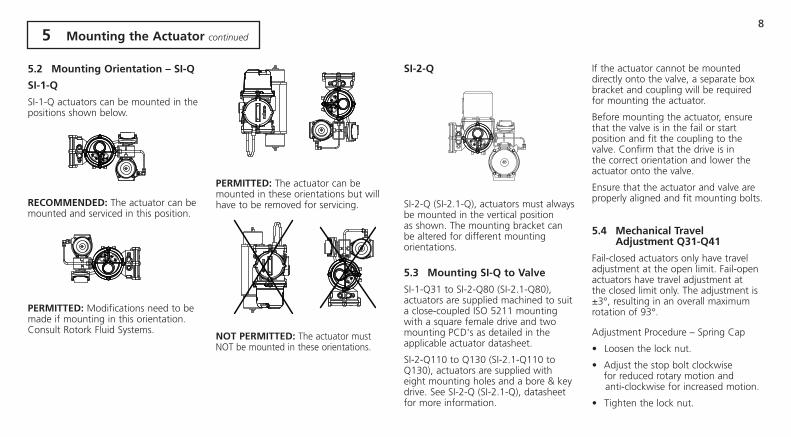
5.2 mounting Orientation – Si-Q
Si-1-Q
SI-1-Q actuators can be mounted in the positions shown below.
RECOmmENdEd: The actuator can be mounted and serviced in this position.
PERmiTTEd: Modifications need to be made if mounting in this orientation. Consult Rotork Fluid Systems.
PERmiTTEd: The actuator can be mounted in these orientations but will have to be removed for servicing.
NOT PERmiTTEd: The actuator must NOT be mounted in these orientations.
Si-2-Q
SI-2-Q (SI-2.1-Q), actuators must always be mounted in the vertical position as shown. The mounting bracket can be altered for different mounting orientations.
5.3 mounting Si-Q to Valve
SI-1-Q31 to SI-2-Q80 (SI-2.1-Q80), actuators are supplied machined to suit a close-coupled ISO 5211 mounting with a square female drive and two mounting PCD's as detailed in the applicable actuator datasheet.
SI-2-Q110 to Q130 (SI-2.1-Q110 to Q130), actuators are supplied with eight mounting holes and a bore & key drive. See SI-2-Q (SI-2.1-Q), datasheet for more information.
If the actuator cannot be mounted directly onto the valve, a separate box bracket and coupling will be required for mounting the actuator.
Before mounting the actuator, ensure that the valve is in the fail or start position and fit the coupling to the valve. Confirm that the drive is in the correct orientation and lower the actuator onto the valve.
Ensure that the actuator and valve are properly aligned and fit mounting bolts.
5.4 mechanical Travel Adjustment Q31-Q41
Fail-closed actuators only have travel adjustment at the open limit. Fail-open actuators have travel adjustment at the closed limit only. The adjustment is ±3°, resulting in an overall maximum rotation of 93°.
Adjustment Procedure – Spring Cap
• Loosen the lock nut.
• Adjust the stop bolt clockwise for reduced rotary motion and anti-clockwise for increased motion.
• Tighten the lock nut.
5 mounting the Actuator continued

9
WARNiNG:Q41 actuators have two travel adjustment screws. It is important that both screws are adjusted equally to ensure that both are in contact with the piston.
5.5 mechanical Travel Adjustment Q51-Q80
FAIL-CLOSED ACTUATORS: Use adjustment screw "A" for the closed position and adjustment screw "B" for the open position.
FAIL-OPEN ACTUATORS: Use adjustment screw "B" for the closed position and adjustment screw "A" for the open position.
Actuators can be adjusted by +/- 3° in both open and closed position resulting in an overall maximum rotation of 96°.
Adjustment Procedure
• Loosen the lock nut.
• Turn set screw to reach the desired position.
• Tighten the lock nut.
Q51 & Q70 Actuators
Q60, Q61 & Q80 Actuators
5.6 mechanical Travel Adjustment Q110-130
Travel is adjusted by stop bolts in the hydraulic cylinder and spring canister. On fail-closed actuators the hydraulic cylinder bolt adjusts the closed limit and the spring canister bolt adjusts the open limit. On fail-open actuators the hydraulic cylinder bolt adjusts the open limit and the spring canister bolt adjusts the closed limit. Actuators can be adjusted by ±5° in both open and closed directions resulting in an overall maximum rotation of 100°.
Hydraulic Cylinder Adjustment
• Remove the stop bolt cover and loosen the stop nut.
• Adjust the stop bolt clockwise for reduced rotary motion and anti clockwise for increased rotary motion.
• Once the desired position is achieved, tighten the stop nut, ensuring that the sealing washer is properly centred on the shaft and seated in the machined recess in the flange.
• Re-install the stop cover, ensuring that the sealing washer is properly centred on the shaft and seated in the machined recess in the stop cover.
Spring Canister Adjustment
• Remove the spring stop cap.
• Adjust the stop bolt clockwise for reduced and anti-clockwise for increased rotary motion.
• Once the desired position is achieved, replace the spring stop cap.
5 mounting the Actuator continued
Adjustment Screw A
Adjustment Screw B
Adjustment Screw B
Adjustment Screw A
Stop Screw
Sealing Washer
Stop Nut
Sealing Washer
Stop Bolt Cover
Spring Stop
Spring Stop Cap
10 5 mounting the Actuator continued
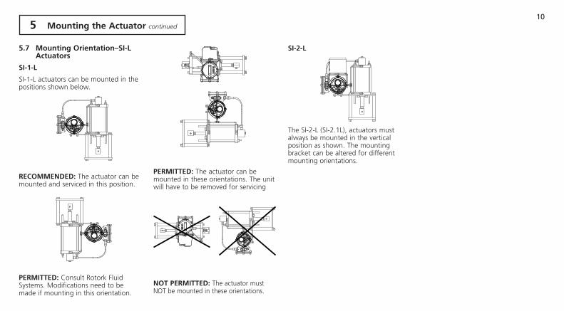
5.7 mounting Orientation–Si-l Actuators
Si-1-l
SI-1-L actuators can be mounted in the positions shown below.
RECOmmENdEd: The actuator can be mounted and serviced in this position.
PERmiTTEd: Consult Rotork Fluid Systems. Modifications need to be made if mounting in this orientation.
PERmiTTEd: The actuator can be mounted in these orientations. The unit will have to be removed for servicing
NOT PERmiTTEd: The actuator must NOT be mounted in these orientations.
Si-2-l
The SI-2-L (SI-2.1L), actuators must always be mounted in the vertical position as shown. The mounting bracket can be altered for different mounting orientations.
11
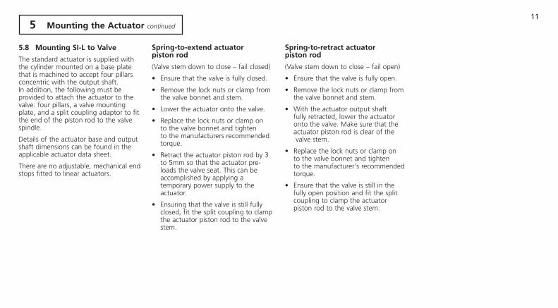
5.8 mounting Si-l to Valve
The standard actuator is supplied with the cylinder mounted on a base plate that is machined to accept four pillars concentric with the output shaft. In addition, the following must be provided to attach the actuator to the valve: four pillars, a valve mounting plate, and a split coupling adaptor to fit the end of the piston rod to the valve spindle.
Details of the actuator base and output shaft dimensions can be found in the applicable actuator data sheet.
There are no adjustable, mechanical end stops fitted to linear actuators.
Spring-to-extend actuator piston rod
(Valve stem down to close – fail closed)
• Ensure that the valve is fully closed.
• Remove the lock nuts or clamp from the valve bonnet and stem.
• Lower the actuator onto the valve.
• Replace the lock nuts or clamp on to the valve bonnet and tighten to the manufacturers recommended torque.
• Retract the actuator piston rod by 3 to 5mm so that the actuator pre- loads the valve seat. This can be accomplished by applying a temporary power supply to the actuator.
• Ensuring that the valve is still fully closed, fit the split coupling to clamp the actuator piston rod to the valve stem.
Spring-to-retract actuator piston rod
(Valve stem down to close – fail open)
• Ensure that the valve is fully open.
• Remove the lock nuts or clamp from the valve bonnet and stem.
• With the actuator output shaft fully retracted, lower the actuator onto the valve. Make sure that the actuator piston rod is clear of the valve stem.
• Replace the lock nuts or clamp on to the valve bonnet and tighten to the manufacturer's recommended torque.
• Ensure that the valve is still in the fully open position and fit the split coupling to clamp the actuator piston rod to the valve stem.
5 mounting the Actuator continued
12
WARNiNG:Ensure all power supplies are isolated before removing actuator covers.
Check that the supply voltage is the same as that stamped on actuator nameplate.
A switch or circuit breaker must be included in electric supply to the actuator. The switch or circuit breaker shall be mounted as close to the actuator as possible and shall be marked to indicate that it is the disconnecting device for that particular actuator. The actuator must be protected with a suitably rated overcurrent protection device as defined on the applicable wiring diagram.
6.1 Earth/Ground Connections
An M6 earth stud is located adjacent to the conduit entries for attachment of an external protective earthing strap. An internal earth terminal is also provided on the terminal bung, however it must not be used alone as the protective Earth Connection.
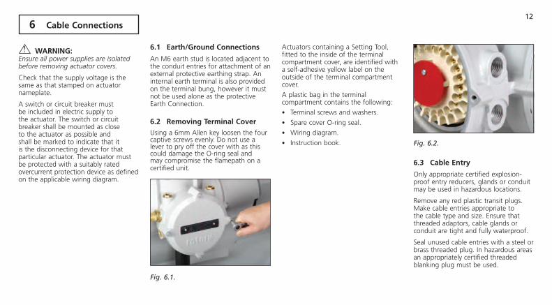
6.2 Removing Terminal Cover
Using a 6mm Allen key loosen the four captive screws evenly. Do not use a lever to pry off the cover with as this could damage the O-ring seal and may compromise the flamepath on a certified unit.
Fig. 6.1.
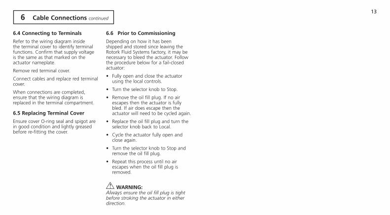
Actuators containing a Setting Tool, fitted to the inside of the terminal compartment cover, are identified with a self-adhesive yellow label on the outside of the terminal compartment cover.
A plastic bag in the terminal compartment contains the following:
• Terminal screws and washers.
• Spare cover O-ring seal.
• Wiring diagram.
• Instruction book. Fig. 6.2.
6.3 Cable Entry
Only appropriate certified explosion-proof entry reducers, glands or conduit may be used in hazardous locations.
Remove any red plastic transit plugs. Make cable entries appropriate to the cable type and size. Ensure that threaded adaptors, cable glands or conduit are tight and fully waterproof.
Seal unused cable entries with a steel or brass threaded plug. In hazardous areas an appropriately certified threaded blanking plug must be used.
6 Cable Connections
13
6.4 Connecting to Terminals
Refer to the wiring diagram inside the terminal cover to identify terminal functions. Confirm that supply voltage is the same as that marked on the actuator nameplate.
Remove red terminal cover.
Connect cables and replace red terminal cover.
When connections are completed, ensure that the wiring diagram is replaced in the terminal compartment.
6.5 Replacing Terminal Cover
Ensure cover O-ring seal and spigot are in good condition and lightly greased before re-fitting the cover.
6.6 Prior to Commissioning
Depending on how it has been shipped and stored since leaving the Rotork Fluid Systems factory, it may be necessary to bleed the actuator. Follow the procedure below for a fail-closed actuator:
• Fully open and close the actuator using the local controls.
• Turn the selector knob to Stop.
• Remove the oil fill plug. If no air escapes then the actuator is fully bled. If air does escape then the actuator will need to be cycled again.
• Replace the oil fill plug and turn the selector knob back to Local.
• Cycle the actuator fully open and close again.
• Turn the selector knob to Stop and remove the oil fill plug.
• Repeat this process until no air escapes when the oil fill plug is removed.
WARNiNG:Always ensure the oil fill plug is tight before stroking the actuator in either direction.
6 Cable Connections continued

14
All SI actuator functions are configured to Rotork Fluid Systems standard default settings before despatch unless alternatives have been specified with the order.
Should difficulty be encountered during commissioning the default settings can be reinstated, returning the actuator configuration to its original manufactured state. (See Section 9.3.)
7.1 Procedure OverviewAll SI range actuators are designed to be commissioned without removing any electrical covers.
Setting the electrical limits of travel and other functions are performed by using the Infra-Red Setting Tool. The Setting Tool is certified intrinsically safe to allow commissioning in hazardous areas.
All the commissioning functions are stored in nonvolatile memory in the actuator. The Setting Tool enables the user to view all functions in turn via the actuator display window. Each function can be viewed, its setting checked and, if required, changed within the bounds of that function.
The power supply must be connected and energised for commissioning purposes. The setting procedure is divided into two stages:
1. Primary Functions Setting the electrical end-of-travel limit positions and remote control functions.
Primary functions must be set prior to secondary functions.
2. Secondary Functions Settings cover the control, indication and optional equipment functions.
The default function should be used with caution as settings selected after manufacture may be essential for the safe operation of the valve and/or plant.
Throughout this manual, the top line of the actuator display will be represented in curved brackets "( )" and the bottom line of the actuator display will be represented in square brackets "[ ]".
menu Structure
7 Commissioning Overview
00 ][
Position Display
P? Id
Password
Cr Cr Cr Crossroads Cn rE XX
Configuration Remote Control Further Menus
Secondary FunctionsSettings
Controller Set-upInt. Timer
Help Screens
Primary FunctionsClosed LimitOpen Limit
Primary FunctionsRemote Control

15
7.2 The Setting Tool Pro
Name instruction1. m Key* Display next function down.
2. i Key Display previous function up.
3. k Key* Display next function across right.
4. o Key Display previous function across left.
5. - Key Decrease/change displayed function’s value or option setting.
6. + Key Increase/change displayed function’s value or option setting.
7. Key Non-functional on SI actuators.
8. Key Enter displayed value or option setting.
9. Infra-red transmitter window.
10. Key Non-functional on SI actuators.
11. Key Non-functional on SI actuators.
* Pressing these two arrow keys together exits setting mode and returns the actuator display to the pressure/position indication mode.
Fig. 7.2. The Setting Tool Pro
SpecificationEnclosure: IP54
Certification: ATEX CE 0518 Ex II 1G FM, INT SAFE, Class I, Div 1, Groups A, B, C & D, T4. CSA, Exia, Class I, Div 1, Groups A, B, C & D, T4. Temperature: Tamb = -30 ºC to 50 ºC
Power supply: 2x 1.5V Batteries (supplied and fitted)
Operating range: 0.75m (from actuator display window)
8
2
7
6
5
3
1
4
9
7 Commissioning continued
11
10
16 7 Commissioning continued
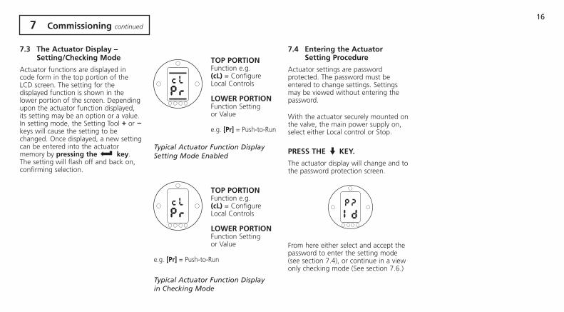
7.3 The Actuator display – Setting/Checking mode
Actuator functions are displayed in code form in the top portion of the LCD screen. The setting for the displayed function is shown in the lower portion of the screen. Depending upon the actuator function displayed, its setting may be an option or a value. In setting mode, the Setting Tool + or - keys will cause the setting to be changed. Once displayed, a new setting can be entered into the actuator memory by pressing the key. The setting will flash off and back on, confirming selection.
TOP PORTiONFunction e.g. (cl) = Configure Local Controls
lOWER PORTiONFunction Setting or Value e.g. [Pr] = Push-to-Run
Typical Actuator Function DisplaySetting Mode Enabled
TOP PORTiONFunction e.g. (cl) = Configure Local Controls
lOWER PORTiONFunction Setting or Value
e.g. [Pr] = Push-to-Run
Typical Actuator Function Display in Checking Mode
7.4 Entering the Actuator Setting Procedure
Actuator settings are password protected. The password must be entered to change settings. Settings may be viewed without entering the password.
With the actuator securely mounted on the valve, the main power supply on, select either Local control or Stop.
PRESS THE m KEy.
The actuator display will change and to the password protection screen.
From here either select and accept the password to enter the setting mode (see section 7.4), or continue in a view only checking mode (See section 7.6.)
17 7 Commissioning continued
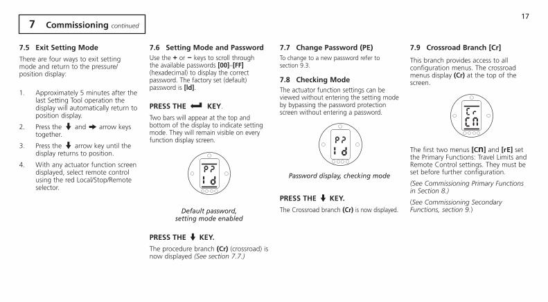
7.5 Exit Setting mode
There are four ways to exit setting mode and return to the pressure/ position display:
1. Approximately 5 minutes after the last Setting Tool operation the display will automatically return to position display.
2. Press the m and k arrow keys together.
3. Press the m arrow key until the display returns to position.
4. With any actuator function screen displayed, select remote control using the red Local/Stop/Remote
selector.
7.6 Setting mode and Password Use the + or - keys to scroll through the available passwords [00]–[FF] (hexadecimal) to display the correct password. The factory set (default) password is [ld].
PRESS THE KEy.
Two bars will appear at the top and bottom of the display to indicate setting mode. They will remain visible on every function display screen.
Default password,setting mode enabled
PRESS THE m KEy.
The procedure branch (Cr) (crossroad) is now displayed (See section 7.7.)
7.7 Change Password (PE)To change to a new password refer to section 9.3.
7.8 Checking modeThe actuator function settings can be viewed without entering the setting mode by bypassing the password protection screen without entering a password.
Password display, checking mode
PRESS THE m KEy.
The Crossroad branch (Cr) is now displayed.
7.9 Crossroad Branch [Cr]
This branch provides access to all configuration menus. The crossroad menus display (Cr) at the top of the screen.
The first two menus [Cn] and [rE] set the Primary Functions: Travel Limits and Remote Control settings. They must be set before further configuration.
(See Commissioning Primary Functions in Section 8.)
(See Commissioning Secondary Functions, section 9.)

18
Fig. 8.1.
The actuator’s Primary Function settings affect the correct operation of the valve by the actuator. If the actuator has been supplied with the valve, the valve maker or supplier may have already made these settings.
This instruction assumes Setting mode has been entered (See Section 7.4.)
Rotork supplied an actuator wiring diagram for this actuator; it will be required to carry out commissioning. If a duplicate is required, contact Rotork Fluid Systems. The actuator nameplate information will be required to provide the proper diagram.
WARNiNG: Settings and functionality should be verified by electric operation of the actuator to ensure correct operation.
8 Commissioning – Primary Functions

19 8 Commissioning – Primary Functions continued
Primary Functions Contents
Section Page
8.1 Configuration Menu 21
lC Closed Limit 22
lO Open Limit 23
8.2 Remote Control Menu 24
rE Remote Control menu 24
rS Remote Select 25
cl Configure Local 26
rP Remote Priority 26
EA ESD Action 27
EO ESD Local Stop Override 27
Ec ESD Type 28
AA Analogue Signal Failure Action 29
SI actuators can be factory set to be clockwise or anti-clockwise to close.
Secondary Functions (See section 9)Fig. 8.2. Primary Setting Function Displays
00 ][ Positional Display
P? Password
Crossroads Cn rE Fn CS It HP Crossroads Configuration Remote Control Settings Controller Set-up Int. Timer Help Screens
LC rS db dC OJ H1 Closed Limit Remote Select Deadband Demand Low I. Timer Enabled Limit Flags
LO cL HS dO Jd H2 Open Limit Configure Local Hysteresis Demand High I. Timer Dir Local Control
rP HL oP (CL) JC H3 Remote Priority Hold Limit Set CPT Closed I. Timer Start Remote Signals
EA LH oP (OP) JO H4 ESD Action Limit Hysteresis Set CPT Open I. Timer Stop Digital Feedback
EO PH LP JS H5 ESD Local Stop Override Press Hysteresis Low Power I. Timer Interval Control Flags 1
Ec Ld PE Jn H6 ESD Type Cls LED Colour Password Edit I. Timer On Time Driver Buffer
AA PP rd JF H7 Analogue Alarm P. Stroke Pos Reset to Defaults I. Timer Off Time Error Flags 1
PS CF JE H8 P. Stroke Limit Confirm Faults I. Timer on ESD Error Flags 2
H9 Error Flags 2
HA Driver Logic

20
The (Cr) menu gives access to the Configuration settings [Cn].
This menu covers setting the Open and Closed Limit.
PRESS THE m KEy as required to access the various Configuration menu items.
8.1 Configurationmenu
CrCn
Set the closed position limit. Using the local controls, move the actuator electrically to the valve's fully closed mechanical limit and back off 2% by running the actuator in the open direction.
For example, if the closed mechanical limit shows a figure of 13 on the display, move the actuator open until the display shows 15, indicating 15% of total positional feedback span.
PRESS THE KEy.
The displayed option will flash indicating that it has been set.
00 ][ Positional Display
P? Password
Cn rE Configuration Remote Control
lC rS Closed Limit Remote Select
lO cl Open Limit Configure Local
00 rP ][ Remote Priority
Positional Display EA ESD Action
EO ESD Local Stop Override
Ec ESD Type
AA Analogue Alarm
Closed limit LCCrCn
21
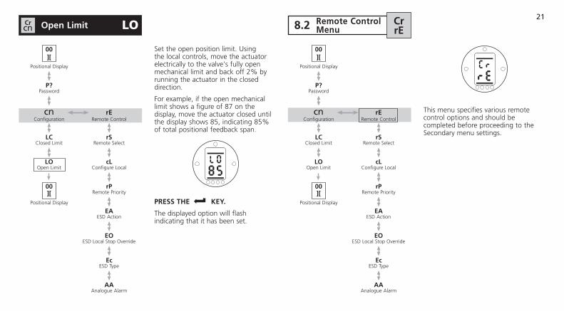
Set the open position limit. Using the local controls, move the actuator electrically to the valve's fully open mechanical limit and back off 2% by running the actuator in the closed direction.
For example, if the open mechanical limit shows a figure of 87 on the display, move the actuator closed until the display shows 85, indicating 85% of total positional feedback span.
PRESS THE KEy.
The displayed option will flash indicating that it has been set.
00 ][ Positional Display
P? Password
Cn rE Configuration Remote Control
lC rS Closed Limit Remote Select
lO cl Open Limit Configure Local
00 rP ][ Remote Priority
Positional Display EA ESD Action
EO ESD Local Stop Override
Ec ESD Type
AA Analogue Alarm
Open limit LOCrCn
This menu specifies various remote control options and should be completed before proceeding to the Secondary menu settings.
00 ][ Positional Display
P? Password
Cn rE Configuration Remote Control
lC rS Closed Limit Remote Select
lO cl Open Limit Configure Local
00 rP ][ Remote Priority
Positional Display EA ESD Action
EO ESD Local Stop Override
Ec ESD Type
AA Analogue Alarm
8.2 Remote Controlmenu
CrrE

22
Set the remote control type. There five options available:
[OF] No remote control system available. Actuator subject to local pushbutton control only.
[rE] Hard-wired remote control. The actuator will respond to signals from the remote digital inputs.
[OP] Option Control. This option should be selected if the actuator is fitted with an optional control card: Pakscan, Profibus, Foundation Fieldbus, DeviceNet or Modbus.
[OE] Option Control with hard-wired ESD override. Select this option for use with any of the above [OP] options when a hard-wired ESD override facility is also required.
[Ai] Analogue Control. The actuator is remotely controlled by an external analogue signal in the range 0 to 20 mA or 0 to 10 Volts with or without offset zero. See section 9.3 (dC), (dO) for signal/actuator calibration instructions.
00 ][ Positional Display
P? Password
Cn rE Configuration Remote Control
lC rS Closed Limit Remote Select
lO cl Open Limit Configure Local
00 rP ][ Remote Priority
Positional Display EA ESD Action
EO ESD Local Stop Override
Ec ESD Type
AA Analogue Alarm
Remote Select rSCrrE
Press the + or -keys to move to the next or previous option.
After selection of the required remote control option press the key.
The displayed option will flash indicating that it has been set.
PRESS THE m KEy to display the next item in the Remote Controls Menu.
Remote Select – Hard wired remote control

23
There are two options available to configure operation of the local controls: Push-to-Run [Pr] and Maintain [nn]. In Push to Run mode, actuator travel will stop when the switch is released. In Maintain mode, once travel is initiated, the actuator will run until it reaches the stop limits set in (lC) or (lO) The default setting is Push-to-Run.
If self-maintained actuator local control is required press the + or - key. The display will change to [nn].
PRESS THE KEy.
The displayed option will flash indicating that it has been set.
PRESS THE m KEy to display the next item in the Remote Controls Menu.
Remote Priority sets the overriding priority in the event both Open and Close inputs are asserted simultaneously. The three available options are Close (Cl), Open (OP) or Stay-in-Position (SP). The default setting is Stay-in-Position.
If Close priority is required press the + or - key until [Cl] is displayed.
If Open priority is required press the + or - key until [OP] is displayed.
PRESS THE KEy.
The displayed option will flash indicating that it has been set.
PRESS THE m KEy to display the next item in the Remote Controls Menu.
00 ][ Positional Display
P? Password
Cn rE Configuration Remote Control
lC rS Closed Limit Remote Select
lO cl Open Limit Configure Local
00 rP ][ Remote Priority
Positional Display EA ESD Action
EO ESD Local Stop Override
Ec ESD Type
AA Analogue Alarm
00 ][ Positional Display
P? Password
Cn rE Configuration Remote Control
lC rS Closed Limit Remote Select
lO cl Open Limit Configure Local
00 rP ][ Remote Priority
Positional Display EA ESD Action
EO ESD Local Stop Override
Ec ESD Type
AA Analogue Alarm
Configure local cLCrrE Remote Priority rPCr
rE
Configure Local – Maintain mode
Remote Priority – Stay-in-Position

24
Set the action to be taken when an ESD signal is received. Their are four options: De-energise all solenoid valves [ E], Close [ C], Open [ O], or Stay-in-Position [iP]. The default setting is De-energise all solenoid valves.
If Close action is required press the + or - key until [ C] is displayed.
If Open action is required press the + or - key until [ O] is displayed.
If stop in position action is required press the + or - key until [iP] is displayed
PRESS THE KEy.
The displayed option will flash indicating that it has been set.
PRESS THE m KEy to display the next item in the Remote Controls Menu.
This setting determines if an ESD signal will override a local stop command. The two options are On [On] and Off [OF]. The default setting is [OF] no override.
If local stop override is required press the + or - key until [On] is displayed
PRESS THE KEy.
The displayed option will flash indicating that it has been set.
PRESS THE m KEy to display the next item in the Remote Controls Menu.
00 ][ Positional Display
P? Password
Cn rE Configuration Remote Control
lC rS Closed Limit Remote Select
lO cl Open Limit Configure Local
00 rP ][ Remote Priority
Positional Display EA ESD Action
EO ESD Local Stop Override
Ec ESD Type
AA Analogue Alarm
00 ][ Positional Display
P? Password
Cn rE Configuration Remote Control
lC rS Closed Limit Remote Select
lO cl Open Limit Configure Local
00 rP ][ Remote Priority
Positional Display EA ESD Action
EO ESD Local Stop Override
Ec ESD Type
AA Analogue Alarm
ESd Action EACrrE ESd local Stop Override EOCr
rE
ESD Action – De-energise all solenoid valves
ESD Local Stop Override – Do not override

25
Set the ESD contact type. There are two options:
[nO] - Apply signal to initiate ESD.
[nC] - Remove signal to initiate ESD.
The default setting is normally open.
If a normally closed contact is required press the + or - key until [nC] is displayed.
PRESS THE KEy.
The displayed option will flash indicating that it has been set.
PRESS THE m KEy to display the next item in the Remote Controls Menu.
00 ][ Positional Display
P? Password
Cn rE Configuration Remote Control
lC rS Closed Limit Remote Select
lO cl Open Limit Configure Local
00 rP ][ Remote Priority
Positional Display EA ESD Action
EO ESD Local Stop Override
Ec ESD Type
AA Analogue Alarm
ESd Contact Type ECCrrE
Set the action to be taken upon loss of analogue signal. There are three options:
No alarm [OF].
Alarm [ A].
Alarm and ESD [AE].
The default setting is no alarm.
If an alarm is required press the + or - key until [ A] is displayed.
If an alarm plus ESD is required press the + or - key until [AE] is displayed.
PRESS THE KEy.
The displayed option will flash indicating that it has been set.
00 ][ Positional Display
P? Password
Cn rE Configuration Remote Control
lC rS Closed Limit Remote Select
lO cl Open Limit Configure Local
00 rP ][ Remote Priority
Positional Display EA ESD Action
EO ESD Local Stop Override
Ec ESD Type
AA Analogue Alarm
Analogue Signal Failure Action AACrrE
ESD Contact Type – Normally open
Analogue Signal Failure Action – No alarm
26
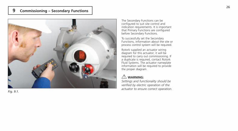
The Secondary Functions can be configured to suit site control and indication requirements. It is important that Primary Functions are configured before Secondary Functions.
To successfully set the Secondary Functions, information about the site or process control system will be required.
Rotork supplied an actuator wiring diagram for this actuator; it will be required to carry out commissioning. If a duplicate is required, contact Rotork Fluid Systems. The actuator nameplate information will be required to provide the proper diagram.
WARNiNG: Settings and functionality should be verified by electric operation of the actuator to ensure correct operation.
9 Commissioning – Secondary Functions
Fig. 9.1.

27 9 Commissioning –
Secondary Functions continued
Secondary Functions Contents
Section Page
9.1 Settings Menu 28
9.2 Controller Set-up Menu 32
9.3 Interrupter Timer 42
9.4 Help Screens 45
Fig. 9.2. Secondary Setting Function Displays
00 ][ Positional Display
P? Password
Crossroads Cn rE Fn CS It HP Crossroads Configuration Remote Control Settings Controller Set-up Int. Timer Help Screens
LC rS db dC OJ H1 Closed Limit Remote Select Deadband Demand Low I. Timer Enabled Limit Flags
LO cL HS dO Jd H2 Open Limit Configure Local Hysteresis Demand High I. Timer Dir Local Control
rP HL oP (CL) JC H3 Remote Priority Hold Limit Set CPT Closed I. Timer Start Remote Signals
EA LH oP (OP) JO H4 ESD Action Limit Hysteresis Set CPT Open I. Timer Stop Digital Feedback
EO PH LP JS H5 ESD Local Stop Override Press Hysteresis Low Power I. Timer Interval Control Flags 1
Ec Ld PE Jn H6 ESD Type Cls LED Colour Password Edit I. Timer On Time Driver Buffer
AA PP rd JF H7 Analogue Alarm P. Stroke Pos Reset to Defaults I. Timer Off Time Error Flags 1
PS CF JE H8 P. Stroke Limit Confirm Faults I. Timer on ESD Error Flags 2
H9 Error Flags 2
HA Driver Logic
Primary Functions(See Section 8.)
28
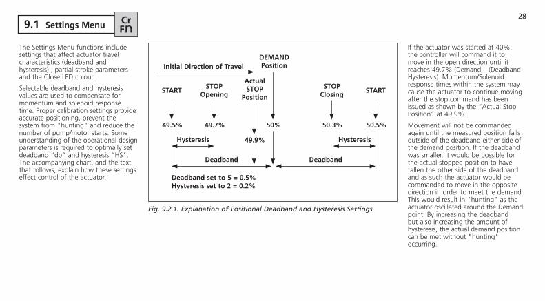
The Settings Menu functions include settings that affect actuator travel characteristics (deadband and hysteresis) , partial stroke parameters and the Close LED colour.
Selectable deadband and hysteresis values are used to compensate for momentum and solenoid response time. Proper calibration settings provide accurate positioning, prevent the system from "hunting" and reduce the number of pump/motor starts. Some understanding of the operational design parameters is required to optimally set deadband “db” and hysteresis “HS". The accompanying chart, and the text that follows, explain how these settings effect control of the actuator.
If the actuator was started at 40%, the controller will command it to move in the open direction until it reaches 49.7% (Demand – (Deadband-Hysteresis). Momentum/Solenoid response times within the system may cause the actuator to continue moving after the stop command has been issued as shown by the “Actual Stop Position” at 49.9%.
Movement will not be commanded again until the measured position falls outside of the deadband either side of the demand position. If the deadband was smaller, it would be possible for the actual stopped position to have fallen the other side of the deadband and as such the actuator would be commanded to move in the opposite direction in order to meet the demand. This would result in "hunting" as the actuator oscillated around the Demand point. By increasing the deadband but also increasing the amount of hysteresis, the actual demand position can be met without "hunting" occurring.
9.1 Settings menu CrFn
Fig. 9.2.1. Explanation of Positional Deadband and Hysteresis Settings
initial direction of TraveldEmANd Position
50%
ActualSTOP
Position
49.9%
49.7%
STOPOpening
49.5%
START
50.3%
STOPClosing
50.5%
START
Hysteresis
deadband deadband
Hysteresis
deadband set to 5 = 0.5% Hysteresis set to 2 = 0.2%

29 Posn. deadband db
Set Position Deadband adjustment. In the display, Position Deadband is expressed as a % of operating range. Analogue signal deadband is adjustable over a range of 0.1% to 9.9%. Adjustments are made in 0.1% increments.
The default value is 1% [10].
Used with analogue control only. Not used with option cards.
Press the + or -keys to increase or decrease the set value.
When the desired value is on the display PRESS THE m KEy
The displayed value will flash indicating that it has been set.
PRESS THE m KEy to display the next item in the Functions Menu.
Set the Position Hysteresis adjustment. In the display, Position Hysteresis is expressed as a % of operating range. Analogue signal hysteresis is adjustable over a range of 0.1% to 9.9%. Adjustments are made in 0.1% increments.
The default value is 0.5% [05].
Press the + or -keys to increase or decrease the set value.
When the desired value is on the display PRESS THE m KEy
The displayed value will flash indicating that it has been set.
PRESS THE m KEy to display the next item in the Functions Menu.
Used with analogue control only. Not used with option cards.
Configure Limit Maintenance. There are two options available:
On [On]
Off [OF]
The default setting is on.
When the hold limit is on:
1. In order to maintain the pressure limits the pump/motor will run if the pressure drop is greater than that set in [PH].
2. In order to maintain the position limits as set in [lO] and [lC] the pump/motor will run if the actuator moves off the limit by the amount set in [lH].
If Hold Limit is not required press the + or -keys until [OF] is displayed.
PRESS THE m KEy
The displayed value will flash indicating that it has been set.
PRESS THE m KEy to display the next item in the Functions Menu.
CrFn Posn. Hysteresis HSCrFn Hold limit HLCr
FnCrFn
In the display Limit Hysteresis is expressed as a % of operating range where 10 = 1%.
The default value is 0.5% [05] Hysteresis for Position Limit.
The minimum settable value is 0.1% and the maximum settable value is 9.9%.
Press the + or - key to increase or decrease the set value.
When the desired value is on the display PRESS THE KEy.
The displayed value will flash indicating that it has been set.
PRESS THE m KEy to display the next item in the Functions Menu.
limit Hysteresis LHCrFn
30
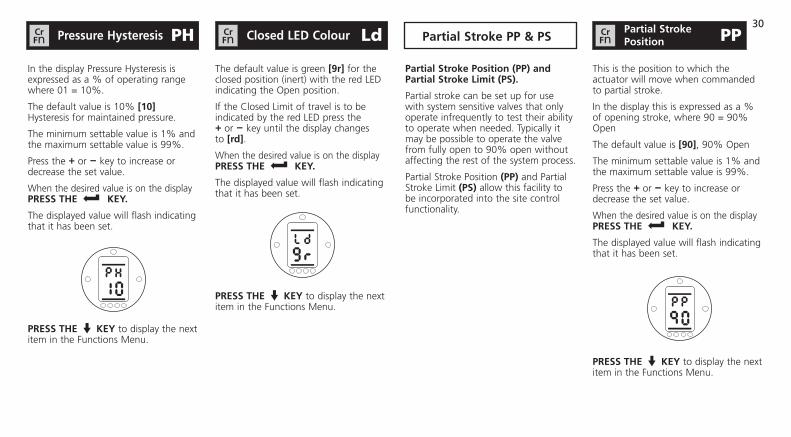
In the display Pressure Hysteresis is expressed as a % of operating range where 01 = 10%.
The default value is 10% [10] Hysteresis for maintained pressure.
The minimum settable value is 1% and the maximum settable value is 99%.
Press the + or - key to increase or decrease the set value.
When the desired value is on the display PRESS THE KEy.
The displayed value will flash indicating that it has been set.
PRESS THE m KEy to display the next item in the Functions Menu.
The default value is green [9r] for the closed position (inert) with the red LED indicating the Open position.
If the Closed Limit of travel is to be indicated by the red LED press the + or - key until the display changes to [rd].
When the desired value is on the display PRESS THE KEy.
The displayed value will flash indicating that it has been set.
PRESS THE m KEy to display the next item in the Functions Menu.
Pressure Hysteresis PHCrFn Closed lEd Colour LdCr
Fn
Partial Stroke Position (PP) and Partial Stroke limit (PS).
Partial stroke can be set up for use with system sensitive valves that only operate infrequently to test their ability to operate when needed. Typically it may be possible to operate the valve from fully open to 90% open without affecting the rest of the system process.
Partial Stroke Position (PP) and Partial Stroke Limit (PS) allow this facility to be incorporated into the site control functionality.
This is the position to which the actuator will move when commanded to partial stroke.
In the display this is expressed as a % of opening stroke, where 90 = 90% Open
The default value is [90], 90% Open
The minimum settable value is 1% and the maximum settable value is 99%.
Press the + or - key to increase or decrease the set value.
When the desired value is on the display PRESS THE KEy.
The displayed value will flash indicating that it has been set.
PRESS THE m KEy to display the next item in the Functions Menu.
PPCrFn
Partial StrokePosition Partial Stroke PP & PS

31
This is the position from which the actuator should be commanded to partial stroke and will be either the Open Limit of travel or the Closed Limit of travel.
The default value is [OP], the Open Limit.
If the Closed Limit is the position from which the actuator should be commanded to partial stroke use the + or - keys until [Cl] is displayed.
PRESS THE KEy.
The displayed option will flash indicating that it has been set.
PRESS THE m KEy to display the next item in the Functions Menu.
PSCrFn
Partial Strokelimit
32
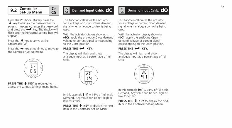
From the Positional Display press the m key to display the password entry screen. If necessary, enter the password and press the key. The display will flash and the horizontal setting bars will appear.
Press the m key to arrive at the Crossroads (Cr).
Press the k key three times to move to the Controller Set-up menu.
PRESS THE m KEy as required to access the various Settings menu items.
This function calibrates the actuator for a voltage or current Close demand signal when analogue control is being used.
With the actuator display showing (dC), apply the analogue Close demand voltage or current signal corresponding to the Close position.
PRESS THE KEy.
The display will flash and show analogue input as a percentage of full scale.
In this example [14] = 14% of full scale Demand. Any value can be set, high or low for either.
PRESS THE m KEy to display the next item in the Controller Set-up Menu.
This function calibrates the actuator for a voltage or current Open demand signal when analogue control is being used.
With the actuator display showing (dO), apply the analogue Open demand voltage or current signal corresponding to the Open position.
PRESS THE KEy.
The display will flash and show analogue input as a percentage of full scale.
In this example [91] = 91% of full scale Demand. Any value can be set, high or low for either.
PRESS THE m KEy to display the next item in the Controller Set-up Menu.
demand input Calib. dCCrCS demand input Calib. dOCr
CS 9.2 CrCS
ControllerSet-up menu

33
Setting instructions for actuators where the Current Position Transmitter (CPT) is in use. This provides an analogue 4–20 mA output position feedback signal.
NOTE: The CPT loop is powered by the actuator as standard.
Connect a current measuring device to the CPT terminals. Press the + or – keys until the required output is shown on the measuring device for the Closed limit position.
PRESS THE KEy.
The display will flash to indicate that the option has been set.
PRESS THE m KEy to display the next item in the Controller Set-up Menu.
Press the + or – keys until the required output is shown on the measuring device for the Open limit position.
PRESS THE KEy.
The display will flash to indicate that the option has been set.
PRESS THE m KEy to display the next item in the Controller Set-up Menu.
It is possible to use an external supply such as a solar power supply for the actuator’s 24 VDC system. If this is the case it is beneficial to limit current consumption while the actuator is at rest.
There are 3 menu options associated with this function,
[OF] Low Power function Off.This is the default setting.
[On] Low power ON. In this mode the display backlight will be switched off when not being used for set-up.
[El] Extra low power ON. In this mode the function of the monitor relay is inverted and the CPT disabled to further reduce power consumption.
Use the + or - keys to select from the above options.
When the desired value is on the display PRESS THE KEy.
The display will flash to indicate that the desired option has been accepted.
Low power function off
PRESS THE m KEy to display the next item in the Controller Set-up Menu.
CPT Current Calibration oPCrCS low Power mode LPCr
CS

34
The default value is [id].
To configure a new password, the actuator must be in setting mode.
The value for the password will only be displayed if it has been entered correctly and accepted.
Press the + or - keys to change the password in the range HEX [00] to [FF] until the desired password is displayed.
PRESS THE KEy.
The displayed option will flash indicating that it has been set.
New Password set as IE
Next time that the setting mode is required it will be necessary to enter the new password and press the key.
PRESS THE m KEy to display the next item in the Controller Set-up Menu.
Password Edit PECrCS

35
All SI actuator functions are configured to factory default (standard) settings before despatch (see the table opposite). Alternative factory settings can be requested at time of order.
Any settings entered during site commissioning will overwrite factory defaults. If difficulty is encountered during commissioning the default settings can be reinstated but note that all Primary and Secondary Functions including limit positions will return to their original factory default setting.
Standard factory default settings for Si actuators:
Function default Setting
(P?) Password Will be reset to [id]
Primary Functions – [rE] Remote Control(rS) Remote Select [rE] Hardwired Control
(cl) Configure Local Controls [nn] Maintained
(rP) Remote Priority [SP] Stayput
(EA) ESD Action [ E] De-energise all Solenoid Valves
(EO) ESD Local Stop Override [OF] Do not Override
(Ec) ESD Contact Type [nO] Normally Open
(AA) Analogue Signal Failure Action [OF] No Alarm
Secondary Functions – [Fn] Settings(db) Position Deadband Adjustment [10] 1.0%
(hS) Position Hysteresis Adjustment [05] 0.5%
(Hl) Hold Position Limit [On] Hold Limit
(lH) Position Limit Hysteresis [05] 0.5%
(PH) Hysteresis for Maintained Pressure [10] 10%
(ld) Closed LED Colour [9r] Green
(PP) Partial Stroke Position [90] 90% Open
Reset to defaults rdCrCS

36
Standard factory default settings for Si actuators:
Function default Setting
Secondary Functions – [CS] Controller Set-up(lP) Low Power Mode Selection [OF] Not Low Power
Secondary Functions – [it] interrupter Timer
(OJ) Interrupter Timer Enable [OF] Timer Off
(Jd) Interrupter Timer Start Direction [Cl] Start Closing
(JC) Interrupter Timer Close Position [25] 25% Open
(JO) Interrupter Timer Open Position [25] 25% Open
(JS) Interrupter Timer Interval [OF] Time In 100ms
(JE) Interrupter Timer ESD Override [OF] No Override
Having selected (rd) in the [CS] Controller Set-up menu, the display will show the current password, for example [id].
Use the + key to increase the password value by 1, [iE] in this example.
PRESS THE KEy.
All settings are returned to factory default values.
Reset to defaults continued rdCrCS

37
In the event of a fault occurring, a fault indication icon will appear at the top of the display the displayed information will alternate between actuator pressure/position and fault code screens.
Fault Icon
Alternating Display e.g., (FA) = Fault, [OP] =Over Pressure
The accompanying table defines the fault displays and the state of the associated Monitor Relay and Fault Relays. If there is more than one fault, then the highest priority fault will be displayed first. After this fault has been cleared the next highest priority fault will be displayed and so on.
After the table individual explanations of each fault code and suggested action is delineated. In some cases it will be necessary to contact Rotork to clear the fault satisfactorily.
Note that although acceptance of the fault may permit the control of the actuator, it is probable that the fault is still present and should be investigated. A full functional test should be carried out to ensure any underlying fault does not effect the actuator performance. If the fault persists contact Rotork Fluid Systems.
Fault Indication Table:
Confirm Faults CFCrCS
display Fault Name monitor Relay Fault Relay
[EE] EEPROM Fault Off On
[hA] Hardware Fault Off On
[lC] Local Controls Fault Off On (assumes Local Stop)
[Pu] Hydraulic Power Unit Fault On On
[Hn] Hand Operation Fault On On
[dr] Solenoid Driver Fault On On
[PO] Position Sensor Fault Off On
[Pr] Pressure Sensor Fault On On
[OP] Over Pressure in Mid-Travel On On
[dl] Actuator Running in Wrong Direction On On
[uP] Under Pressure at End of Travel On On
[St] Actuator Stalled On On
[PS] Unsuccessful Partial Stroke On On
[dn] Loss of Demand Signal (Positioning) On On
38
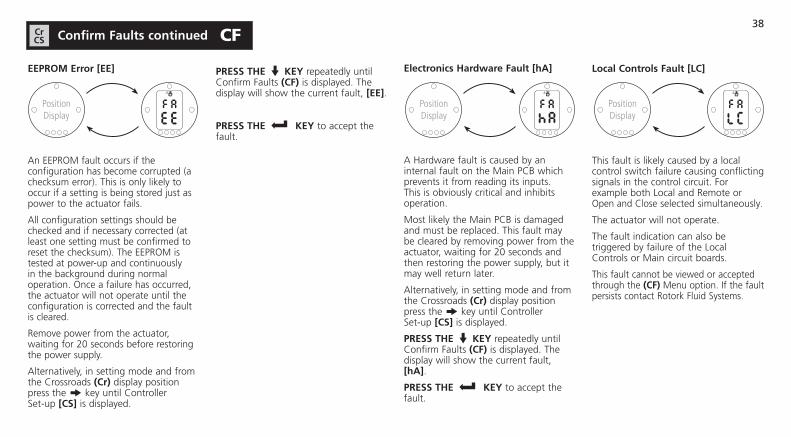
EEPROm Error [EE]
An EEPROM fault occurs if the configuration has become corrupted (a checksum error). This is only likely to occur if a setting is being stored just as power to the actuator fails.
All configuration settings should be checked and if necessary corrected (at least one setting must be confirmed to reset the checksum). The EEPROM is tested at power-up and continuously in the background during normal operation. Once a failure has occurred, the actuator will not operate until the configuration is corrected and the fault is cleared.
Remove power from the actuator, waiting for 20 seconds before restoring the power supply.
Alternatively, in setting mode and from the Crossroads (Cr) display position press the k key until Controller Set-up [CS] is displayed.
PRESS THE m KEy repeatedly until Confirm Faults (CF) is displayed. The display will show the current fault, [EE].
PRESS THE KEy to accept the fault.
Electronics Hardware Fault [hA]
A Hardware fault is caused by an internal fault on the Main PCB which prevents it from reading its inputs. This is obviously critical and inhibits operation.
Most likely the Main PCB is damaged and must be replaced. This fault may be cleared by removing power from the actuator, waiting for 20 seconds and then restoring the power supply, but it may well return later.
Alternatively, in setting mode and from the Crossroads (Cr) display position press the k key until Controller Set-up [CS] is displayed.
PRESS THE m KEy repeatedly until Confirm Faults (CF) is displayed. The display will show the current fault, [hA].
PRESS THE KEy to accept the fault.
local Controls Fault [lC]
This fault is likely caused by a local control switch failure causing conflicting signals in the control circuit. For example both Local and Remote or Open and Close selected simultaneously.
The actuator will not operate.
The fault indication can also be triggered by failure of the Local Controls or Main circuit boards.
This fault cannot be viewed or accepted through the (CF) Menu option. If the fault persists contact Rotork Fluid Systems.
PositionDisplay
PositionDisplay
Confirm Faults continued CFCrCS
PositionDisplay
39
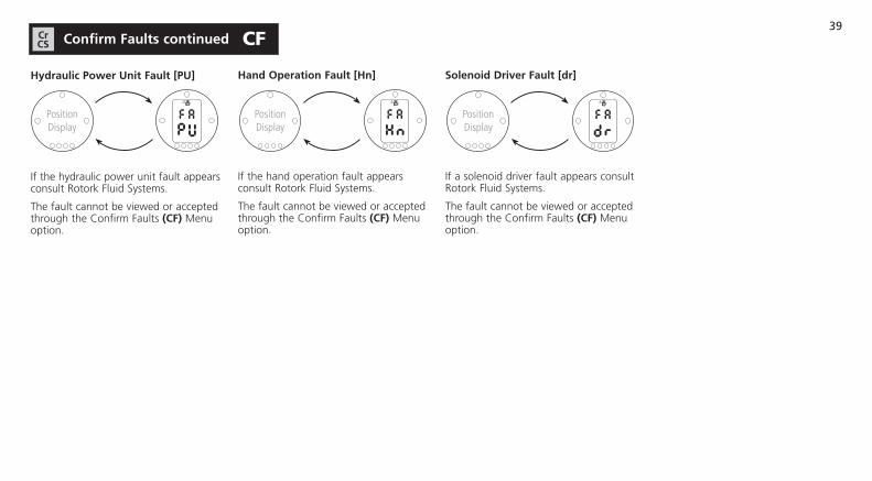
Hydraulic Power unit Fault [Pu]
If the hydraulic power unit fault appears consult Rotork Fluid Systems.
The fault cannot be viewed or accepted through the Confirm Faults (CF) Menu option.
Hand Operation Fault [Hn]
If the hand operation fault appears consult Rotork Fluid Systems.
The fault cannot be viewed or accepted through the Confirm Faults (CF) Menu option.
Solenoid driver Fault [dr]
If a solenoid driver fault appears consult Rotork Fluid Systems.
The fault cannot be viewed or accepted through the Confirm Faults (CF) Menu option.
PositionDisplay
PositionDisplay
Confirm Faults continued CFCrCS
PositionDisplay
40
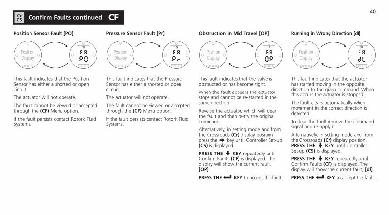
Position Sensor Fault [PO]
This fault indicates that the Position Sensor has either a shorted or open circuit.
The actuator will not operate.
The fault cannot be viewed or accepted through the (CF) Menu option.
If the fault persists contact Rotork Fluid Systems.
Pressure Sensor Fault [Pr]
This fault indicates that the Pressure Sensor has either a shorted or open circuit.
The actuator will not operate.
The fault cannot be viewed or accepted through the (CF) Menu option.
If the fault persists contact Rotork Fluid Systems.
Obstruction in mid Travel [OP]
This fault indicates that the valve is obstructed or has become tight.
When the fault appears the actuator stops and cannot be re-started in the same direction.
Reverse the actuator, which will clear the fault and then re-try the original command.
Alternatively, in setting mode and from the Crossroads (Cr) display position press the k key until Controller Set-up (CS) is displayed.
PRESS THE m KEy repeatedly until Confirm Faults (CF) is displayed. The display will show the current fault, [OP].
PRESS THE KEy to accept the fault.
Running in Wrong direction [di]
This fault indicates that the actuator has started moving in the opposite direction to the given command. When this occurs the actuator is stopped.
The fault clears automatically when movement in the correct direction is detected.
To clear the fault remove the command signal and re-apply it.
Alternatively, in setting mode and from the Crossroads (Cr) display position, PRESS THE m KEy until Controller Set-up (CS) is displayed.
PRESS THE m KEy repeatedly until Confirm Faults (CF) is displayed. The display will show the current fault, [dl].
PRESS THE KEy to accept the fault.
PositionDisplay
PositionDisplay
PositionDisplay
Confirm Faults continued CFCrCS
PositionDisplay
41
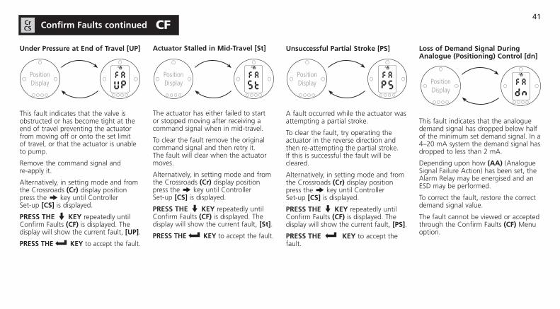
under Pressure at End of Travel [uP]
This fault indicates that the valve is obstructed or has become tight at the end of travel preventing the actuator from moving off or onto the set limit of travel, or that the actuator is unable to pump.
Remove the command signal and re-apply it.
Alternatively, in setting mode and from the Crossroads (Cr) display position press the k key until Controller Set-up [CS] is displayed.
PRESS THE m KEy repeatedly until Confirm Faults (CF) is displayed. The display will show the current fault, [uP].
PRESS THE KEy to accept the fault.
Actuator Stalled in mid-Travel [St]
The actuator has either failed to start or stopped moving after receiving a command signal when in mid-travel.
To clear the fault remove the original command signal and then retry it. The fault will clear when the actuator moves.
Alternatively, in setting mode and from the Crossroads (Cr) display position press the k key until Controller Set-up [CS] is displayed.
PRESS THE m KEy repeatedly until Confirm Faults (CF) is displayed. The display will show the current fault, [St].
PRESS THE KEy to accept the fault.
unsuccessful Partial Stroke [PS]
A fault occurred while the actuator was attempting a partial stroke.
To clear the fault, try operating the actuator in the reverse direction and then re-attempting the partial stroke. If this is successful the fault will be cleared.
Alternatively, in setting mode and from the Crossroads (Cr) display position press the k key until Controller Set-up [CS] is displayed.
PRESS THE m KEy repeatedly until Confirm Faults (CF) is displayed. The display will show the current fault, [PS].
PRESS THE KEy to accept the fault.
loss of demand Signal during Analogue (Positioning) Control [dn]
This fault indicates that the analogue demand signal has dropped below half of the minimum set demand signal. In a 4–20 mA system the demand signal has dropped to less than 2 mA.
Depending upon how (AA) (Analogue Signal Failure Action) has been set, the Alarm Relay may be energised and an ESD may be performed.
To correct the fault, restore the correct demand signal value.
The fault cannot be viewed or accepted through the Confirm Faults (CF) Menu option.
Confirm Faults continued CFCrCS
PositionDisplay
PositionDisplay Position
Display
PositionDisplay
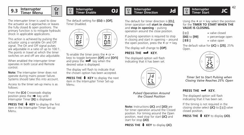
42 9.3 interrupter
Timer menu
The default for timer direction is [Cl], timer operation will start in closing and stop in opening – pulsing operation around the close position.
If pulsing operation is required to stop in closing and start in opening – around the open position, press the + or - key.
The display will change to [OP].
PRESS THE KEy.
The displayed option will flash indicating that it has been set.
Pulsed Operation Around the Closed Position
Note: Instructions (JC) and [JO) are for timer operation around the Closed position. For timing around the Open position, read stop for start (JC) and start for stop (JO).
PRESS THE m KEy to display (JC).
Using the + or - key select the position for the TimER TO START WHEN THE VAlVE iS ClOSiNG.
[ ] [ ] = valve closed[00] to [99] = percentage open[ ] = valve open
The default value for (JC) is [25], 25% Open.
Timer Set to Start Pulsing when Closing Valve Reaches 25% Open
PRESS THE KEy.
The displayed option will flash indicating that it has been set.
If the timing is not required in the closing stroke select (JC) to [ ] [ ] valve closed position.
PRESS THE m KEy to display (JO).
OJCrit
Crit JdCr
it JCCrit
interrupterTimer Enable
interrupterTimer direction
interrupterTimer Start
The interrupter timer is used to slow the actuator as it approaches or leaves the fully closed & open positions. The primary function is to mitigate hydraulic shock in applicable applications.
This action is achieved by pulsing the actuator using a variable On and Off signal. The On and Off signal pulses are adjustable in a ratio of up to 100:1. The points in travel at which the timer switches on and off are also adjustable.
When enabled the interrupter timer operates in both Local and Remote control.
Note: The interrupter timer does not operate during mains power failure. Systems should take this into account.
Access to the timer set-up menu is as follows:
From the (Cr) Crossroads display position press the k key until Interrupter Timer [it] is displayed
PRESS THE m KEy to display the first item in the Interrupter Timer Set-up Menu.
The default setting for (OJ) is [OF], Timer Disabled.
To enable the timer press the + or - keys to toggle between [OF] and [On] and press the key when the desired value is displayed.
The display will flash to indicate that the chosen option has been accepted.
PRESS THE m KEy to display the next item in the Interrupter Timer Set-up Menu.
43
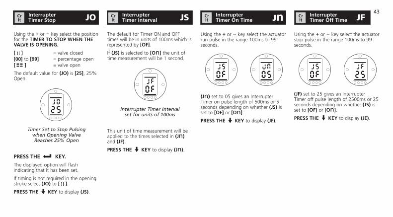
Using the + or - key select the position for the TimER TO STOP WHEN THE VAlVE iS OPENiNG.
[ ] [ ] = valve closed[00] to [99] = percentage open[ ] = valve open
The default value for (JO) is [25], 25% Open.
Timer Set to Stop Pulsingwhen Opening ValveReaches 25% Open
PRESS THE KEy.
The displayed option will flash indicating that it has been set.
If timing is not required in the opening stroke select (JO) to [ ] [ ].
PRESS THE m KEy to display (JS).
The default for Timer ON and OFF times will be in units of 100ms which is represented by [OF].
If (JS) is selected to [On] the unit of time measurement will be 1 second.
Interrupter Timer Interval set for units of 100ms
This unit of time measurement will be applied to the times selected in (Jn) and (JF).
PRESS THE m KEy to display (Jn).
Using the + or - key select the actuator run pulse in the range 100ms to 99 seconds.
(Jn) set to 05 gives an Interrupter Timer on pulse length of 500ms or 5 seconds depending on whether (JS) is set to [OF] or [On].
PRESS THE m KEy to display (JF).
Using the + or - key select the actuator stop pulse in the range 100ms to 99 seconds.
(JF) set to 25 gives an Interrupter Timer off pulse length of 2500ms or 25 seconds depending on whether (JS) is set to [OF] or [On].
PRESS THE m KEy to display (JE).
JOCrit
interrupterTimer Stop JSCr
itinterrupterTimer interval JnCr
itinterrupterTimer On Time JFCr
itinterrupterTimer Off Time

44
The interrupter timer may be overridden when the actuator is under ESD signal command. C or O must be selected for the interrupter timer to override the ESD action. If E is selcted then the interrupter timer does not operate.
Refer to (EA), (EO), (Ec) (see Section 8.2).
The default for ESD override interrupter timer is [OF]. The interrupter timer will continue “stop/start” action during ESD action.
If ESD must override the timer use the + or - to display [On].
ESD Override Timer OFF
PRESS THE KEy.
The displayed option will flash indicating that it has been set.
JECrit
interrupterESd Override

45
With the actuator powered up and Local or Stop selected, eleven Help Screens can be accessed using the Setting Tool. See figure 9.2 for their location in the menu.
With Remote selected press the m key on the Setting Tool. The Help Screens will be displayed.
Each screen uses bars to indicate the status of a particular control or indication function. Each bar reacts to changes in the status of its actuator function by turning ‘‘on’’ or ‘‘off’’.
From the Crossroads display position press the k key until Help Screens [HP] is displayed.
Note: Bar indication is real time and reactive.
PRESS THE m KEy to display the first screen (H1).
Access the following Help Screens to aid in troubleshooting the topics listed:
H1 – Actuator limit status indicators.
H2 – Local control indicators.
H3 – Remote signal indicators.
H4 – Digital feedback indicators.
H5 – Timer, fault and monitor relay indicators.
H6 – Solenoid and pump driver outputs.
H7 – Fault indicators 1.
H8 – Fault indicators 2.
H9 – Fault indicators 3.
HA – Driver logic indicators.
HB – System status indicators.
Open Holding Limit Close Limit
Close Holding Limit Open Limit
Reached Moving Open Closed Pressure
Reached Close Moving Pressure Open
Help Screen 1
Open limitBar On = Actuator has reached Open Limit.
Close limitBar On = Actuator has reached Close Limit.
Reached Open PressureBar On = Actuator has reached Open pressure.
Reached Close PressureBar On = Actuator has reached Close pressure.
moving OpenBar On = Actuator is moving in the Open direction.
moving ClosedBar On = Actuator is moving in the Closed direction.
Holding Open limitBar On = Actuator is maintaining Open Limit position.
Holding Close limitBar On = Actuator is maintaining Close Limit position.
9.4 Help Screens CrHP limit Flags H1Cr
HP

46
Local Mode Hand Selected Operation
Local Local Stop Fitted
Remote Local Mode Close Selected
Local Local Open In-hand
Help Screen 2
local mode SelectedBar On = Local Control selected.
local StopBar On = Local Stop selected.
Remote mode SelectedBar On = Remote Control selected.
local OpenBar On = Local Open selected.
local in-handBar On = Neither local open or local closed selected.
local CloseBar On = Local Close pushbutton operated.
local FittedBar On = Local controls fitted.
Hand OperationBar On = Manual override in use.
Remote 1: Remote 2: Open ESD
Remote 1: Remote 2: Close Maintain
Remote 1: Remote 2: Maintain Close
Remote 1: Remote 2: ESD Open
Help Screen 3
All remote signals designated with "1" are standard hard wired remote inputs.
When a network system such as Pakscan, Profibus or Foundation Fieldbus is in use, remote control inputs are designated with a "2".
Remote 1: OpenBar On = Remote Open Signal Present.
Remote 1: CloseBar On = Remote Close SignalPresent.
Remote 1: maintainBar On = Remote Maintainsignal present.
Remote 1: ESdBar On = ESD signal present.
Remote 2: OpenBar On = Remote Open signalpresent from network.
Remote 2: CloseBar On = Remote Close signalpresent from network.
Remote 2: maintainBar On = Remote Maintainsignal present from network.
Remote 2: ESdBar On = ESD signal presentfrom network.
local Controls H2CrHP Remote Signals H3Cr
HP

47
P.Stroke / Remote- Local Command
Over Pressure
Hydraulic Status
Solenoid Driver Fault
Help Screen 4
Partial Stroke / Remote-local CommandBar On = If in analogue control mode - a remote local command is present. If in hardwired remote control mode - partial stroke command is present.
Over PressureBar On = Hydraulic system over pressure.
Hydraulic StatusBar On = Hydraulic system active.
Solenoid driver FaultBar On = Solenoid driver fault present.
Int Timer Started
Int. Timer Fault Relay Inhibiting Output
Monitor Relay Output
Int. Timer Waiting for First Movement
Help Screen 5
interrupter Timer StartedBar On = Interrupter timer running.
interrupter Timer inhibitingBar On = Interrupter timer off pulse present.
interrupter Timer Waiting for First movementBar On = Interrupter timer is waiting for first movement.
monitor Relay OutputBar On = Monitor relay energised.
Fault Relay OutputBar On = Fault relay energised.
digital Feedback H4CrHP Control Flags H5Cr
HP

48
Solenoid No. 1
Solenoid Closing No. 2
Solenoid Opening No. 3
Pump
Help Screen 6
Solenoid No.1Bar On = Solenoid No.1 energised.
Solenoid No.2Bar On = Solenoid No.2 energised.
Solenoid No.3Bar On = Solenoid No.3 energised.
PumpBar On = Pump running.
OpeningBar On = Actuator opening.
ClosingBar On = Actuator Closing.
Pressure Transducer Fault
Position EEPROM Transducer Checksum Fault
Hardware Solenoid Fault Driver Fault
Local Controls Hydraulic Fault Power Fault
Help Screen 7
EEPROm ChecksumBar On = EEPROM checksum error [EE].
Hardware FaultBar On = Hardware fault present [HA].
local Controls FaultBar On = Local controls fault [lC].
Hydraulic Power FaultBar On = Hydraulic Power fault [Pu].
Solenoid driver FaultBar On = Solenoid Driver error [dr].
Position Transducer FaultBar On = Position Transducer error [Pu].
Pressure Transducer FaultBar On = Pressure Transducer error [Pr].
driver Outputs H6CrHP Error Flags 1 H7Cr
HP

49
Loss of Analogue Demand Signal
Over Partial Pressure in Stroke Mid Travel Fault
Running in Actuator Wrong Stalled Direction
Unable to Actuator Reach Stalled in Pressure Slow Mode
Help Screen 8
Obstruction in mid TravelBar On = Actuator operation has stopped due to an obstruction in mid-travel [OP].
Running in Wrong directionBar On = Actuator is running in the wrong direction [di].
unable to Reach PressureBar On = Actuator is unable to reach required pressure [uP].
Actuator Stalled in Slow modeBar On = Actuator is stalled in slow mode [Sl].
Actuator StalledBar On = Actuator movement is stalled [St].
Partial Stroke FaultBar On = Actuator has failed to complete desired movement [PS].
loss of Analogue demand SignalBar On = Analogue demand signal not present [dn].
Position Checking Fault
Setting Out of Bounds
Help Screen 9
Position Checking FaultBar On = Actuator has a position checking fault.
Setting Out of BoundsBar On = Actuator settings are out of bounds.
Error Flags 2 H8CrHP Error Flags 3 H9Cr
HP
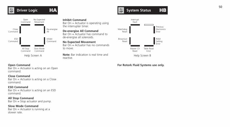
50
Open No Expected Command Movement
Close De-energise Command All
ESD Inhibit Command Command
All Stop Slow Mode Command Command
Help Screen A
Open CommandBar On = Actuator is acting on an Open command.
Close CommandBar On = Actuator is acting on a Close command.
ESd CommandBar On = Actuator is acting on an ESD command.
All Stop CommandBar On = Stop actuator and pump.
Slow mode CommandBar On = Actuator is running at a slower rate.
inhibit CommandBar On = Actuator is operating using the interrupter timer.
de-energise All CommandBar On = Actuator has command to de-energise all solenoids.
No Expected movementBar On = Actuator has no commands to move.
Note: Bar indication is real time and reactive.
Interrupt Fault
Previous Watchdog Electronics Reset Error
Brownout RAM Reset Setting Error
Master Clr Table Read Reset Error
Help Screen B
For Rotork Fluid Systems use only.
driver logic HACrHP System Status HBCr
HP
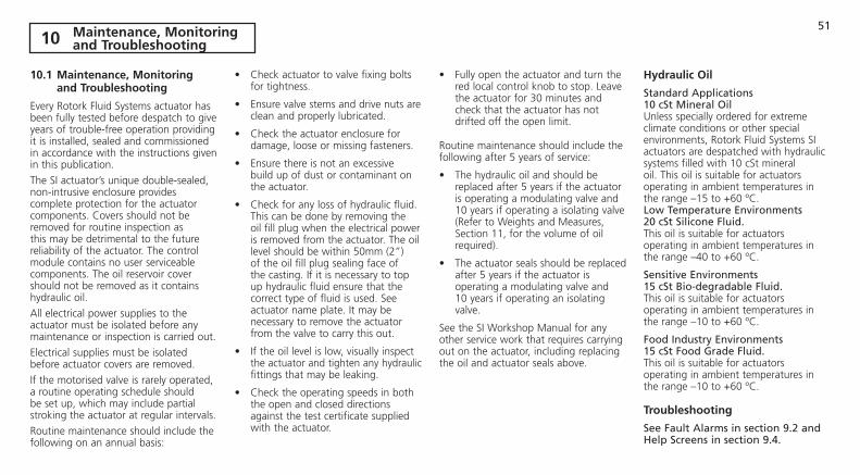
51
10.1 maintenance, monitoring and Troubleshooting
Every Rotork Fluid Systems actuator has been fully tested before despatch to give years of trouble-free operation providing it is installed, sealed and commissioned in accordance with the instructions given in this publication.
The SI actuator’s unique double-sealed, non-intrusive enclosure provides complete protection for the actuator components. Covers should not be removed for routine inspection as this may be detrimental to the future reliability of the actuator. The control module contains no user serviceable components. The oil reservoir cover should not be removed as it contains hydraulic oil.
All electrical power supplies to the actuator must be isolated before any maintenance or inspection is carried out.
Electrical supplies must be isolated before actuator covers are removed.
If the motorised valve is rarely operated, a routine operating schedule should be set up, which may include partial stroking the actuator at regular intervals.
Routine maintenance should include the following on an annual basis:
• Check actuator to valve fixing bolts for tightness.
• Ensure valve stems and drive nuts are clean and properly lubricated.
• Check the actuator enclosure for damage, loose or missing fasteners.
• Ensure there is not an excessive build up of dust or contaminant on the actuator.
• Check for any loss of hydraulic fluid. This can be done by removing the oil fill plug when the electrical power is removed from the actuator. The oil level should be within 50mm (2”) of the oil fill plug sealing face of the casting. If it is necessary to top up hydraulic fluid ensure that the correct type of fluid is used. See actuator name plate. It may be necessary to remove the actuator from the valve to carry this out.
• If the oil level is low, visually inspect the actuator and tighten any hydraulic fittings that may be leaking.
• Check the operating speeds in both the open and closed directions against the test certificate supplied with the actuator.
• Fully open the actuator and turn the red local control knob to stop. Leave the actuator for 30 minutes and check that the actuator has not drifted off the open limit.
Routine maintenance should include the following after 5 years of service:
• The hydraulic oil and should be replaced after 5 years if the actuator is operating a modulating valve and 10 years if operating a isolating valve (Refer to Weights and Measures, Section 11, for the volume of oil required).
• The actuator seals should be replaced after 5 years if the actuator is operating a modulating valve and 10 years if operating an isolating valve.
See the SI Workshop Manual for any other service work that requires carrying out on the actuator, including replacing the oil and actuator seals above.
Hydraulic Oil
Standard Applications 10 cSt Mineral OilUnless specially ordered for extreme climate conditions or other special environments, Rotork Fluid Systems SI actuators are despatched with hydraulic systems filled with 10 cSt mineral oil. This oil is suitable for actuators operating in ambient temperatures in the range –15 to +60 ºC.Low Temperature Environments 20 cSt Silicone Fluid.This oil is suitable for actuators operating in ambient temperatures in the range –40 to +60 ºC.
Sensitive Environments 15 cSt Bio-degradable Fluid. This oil is suitable for actuators operating in ambient temperatures in the range –10 to +60 ºC.
Food Industry Environments 15 cSt Food Grade Fluid. This oil is suitable for actuators operating in ambient temperatures in the range –10 to +60 ºC.
Troubleshooting
See Fault Alarms in section 9.2 and Help Screens in section 9.4.
10 maintenance, monitoring and Troubleshooting
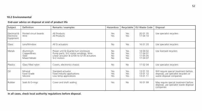
52
End-user advice on disposal at end of product life
Subject Definition Remarks / examples Hazardous Recyclable EU Waste Code Disposal
Electrical & Printed circuit boards All Products Yes Yes 20 01 35 Use specialist recyclers Electronic Wire All Products Yes Yes 17 04 10 Equipment
Glass Lens/Window All SI actuators No Yes 16 01 20 Use specialist recyclers Metals Aluminium Power unit & Quarter-turn enclosure No Yes 14 04 02 Use licensed recyclers Copper/Brass Pump parts, SI-2 motor windings, Wire No Yes 17 04 01 Steel Linear actuator & Q100 to Q130 actuators No Yes 17 05 05 Mixed Metals SI-2 motors No Yes 17 04 07 Plastics Glass filled nylon Covers, electronics chassis No No 17 02 04 Use specialist recyclers Oil Mineral Standard actuator Yes Yes 13 01 10 Will require special treatment before Food Grade Food industry applications Yes Yes 13 01 12 disposal, use specialist recyclers or Silicone Low temp applications Yes Yes 13 01 11 waste disposal companies Rubber Seals & O-rings Cover and shaft sealing Yes No 16 01 99 May require special treatment before disposal, use specialist waste disposal companies
in all cases, check local authority regulations before disposal.
10.2 Environmental

53
Actuator model Nett Weight Volume of Oil kg/lbs (litres / uS Gallons)
SI-1-Q31 27 / 60 4.0 / 1.0
SI-1-Q41 30 / 66 4.5 / 1.2
SI-1-Q51 38 / 84 6.0 / 1.6
SI-1-Q60/1 42 / 93 7.0 / 1.9
SI-2-Q60/1 62 / 137 8.0 / 2.1
SI-2-Q70 98 / 216 17.0 / 4.5
SI-2-Q80 127 / 280 23.0 / 6.0
SI-2-Q110 335 / 739 18.0 / 4.8
SI-2-Q111 365 / 166 34.0 / 9.0
SI-2-Q112 465 / 211 46.0 / 12.2
SI-2-Q120 560 / 1235 41.0 / 10.8
SI-2-Q130 800 / 1764 41.0 / 10.8
Actuator model Nett Weight Volume of Oil kg/lbs (litres / uS Gallons)
SI-1-L80/40 55 / 122 4.0 / 1.0
SI-1-L100/40 75 / 166 4.5 / 1.2
SI-1-L125/65 85 / 188 6.5 / 1.7
SI-1-L160/65 120 / 265 8.5 / 2.3
SI-1-L200/65 160 / 353 11.5 / 3.0
SI-2-L200/105 220 / 485 14.0 / 3.7
SI-2-L250/105 250 / 551 23.0 / 6.0
SI-2-L280/105 270 / 596 31.0 / 8.2
SI-2-L320/105 290 / 640 41.0 / 10.8
SI-2-L350/105 320 / 706 48.5 / 12.8
SI-2-L400/105 Consult Rotork Consult Rotork
SI-2-L450/105 Consult Rotork Consult Rotork
Note - For SI-L actuators, weights and volumes of oil are for standard stroke lengths as stated in the applicable data sheet. Weight listed does not include the valve mounting bracket.
11 Weights and measures
11.1 Weights and measures

54
11.2 Actuator Nameplate
The actuator nameplate is engraved with the following information:
Explosionproof Certification: Details of certification when installed in hazardous environments.
Operating Temperature: Maximum and minimum ambient temperatures for the installation.
model Number.: Full actuator model code. See data sheet for explanation of model code.
Power unit Number.: Model code for power unit only.
Serial Number: Always have this to hand if contacting Rotork Fluid Systems for assistance.
Wiring diagram Number: Wiring diagram will give information on the actuator specification and terminals for incoming cables.
Supply Voltage: Compare this with power supply available on site.
Rating: Power consumption of actuator.
Cable Entries: Specification of size and thread available for cable glands.
Enclosure: The ingress protection rating the actuator is suitable for.
Oil Type: Hydraulic oil type, Standard, Low Temperature, Bio-degradable or Food Grade.
unit Weight: Weight of actuator.
year of manufacture: The year the actuator was manufactured.
11 Weights and measures

55
Rotork SI actuators are approved to many standards. The accompanying list was accurate as of 12 October 2010. Refer to www.rotork.com for the latest information.
Additionally, Rotork can, upon request, supply actuators to national standards not listed. Contact Rotork for details.
Refer to actuator nameplate for unit specific approval details.
Europe – Hazardous Area
Si-1: ATEX (94/9/EC) II 2 G. Ex dme* IIB T4 Temperature -35 °C to +60 °C
Si-1: ATEX (94/9/EC) II 2 G. Ex dme* IIC T4 Temperature -20 °C to +60 °C
Si-2: ATEX (94/9/EC) II 2 G. Ex de* IIB T4 Temperature -40 °C to +60 °C
Si-2.1: ATEX (94/9/EC) II 2 G. Ex de* IIB T4 Temperature -40 °C to +60 °C
Si-2.1: ATEX (94/9/EC) II 2 G. Ex de* IIC T4Temperature -20 °C to +60 °C
international – Hazardous Area
Si-1: IECEx. Ex dme* IIB T4 Temperature -35 °C to +60 °C
Si-2: IECEx. Ex de* IIB T4 Temperature -40 °C to +60 °C
uSA – Hazardous Area
Si-1: FM. Class I, Zone 1, AEx dme* IIB T4 Temperature -35 °C to +60 °C
Si-2: FM. Class I, Zone 1, AEx de* IIB T4 Temperature -40 °C to +60 °C
Canada – Hazardous Area
Si-1: CSA. Class I, Zone 1, Ex dme* IIB T4 Temperature -35 °C to +60 °C
Si-2: CSA. Class I, Zone 1, Ex de* IIB T4 Temperature -40 °C to +60 °C
12 Hazardous Area Approvals
Russia – Hazardous Area
Si-1: GOST R. Ex dme* IIB T4 Temperature -35 °C to +60 °C
Si-1: GOST R. Ex dme* IIC T4 Temperature -20 °C to +60 °C
Si-2: GOST R. Ex de* IIB T4 Temperature -40 °C to +60 °C
Si-2.1: GOST R. Ex de* IIB T4 Temperature -40 °C to +60 °C
Si-2.1: GOST R. Ex de* IIC T4 Temperature -20 °C to +60 °C
Brazil – Hazardous Area
Si-1: INMETRO. BR-Ex dme* IIB T4 Temperature -35 °C to +60 °C
Si-1: INMETRO. BR-Ex dme* IIC T4 Temperature -20 °C to +60 °C
Si-2.1: INMETRO. BR-Ex de* IIB T4 Temperature -40 °C to +60 °C
Si-2.1: INMETRO. BR-Ex de* IIC T4 Temperature -20 °C to +60 °C
* “e” if the increased safety terminal facility is specified on single Ø and DC versions only.Note: Certification temperatures are not operating temperatures, see actuator nameplate for operating temperatures.
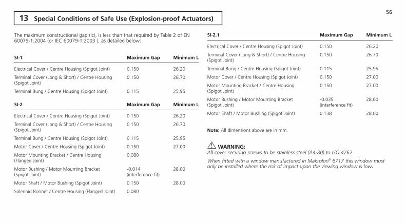
56
The maximum constructional gap (Ic), is less than that required by Table 2 of EN 60079-1:2004 (or IEC 60079-1:2003 ), as detailed below:
Si-1 maximum Gap minimum l
Electrical Cover / Centre Housing (Spigot Joint) 0.150 26.20
Terminal Cover (Long & Short) / Centre Housing 0.150 26.70 (Spigot Joint)
Terminal Bung / Centre Housing (Spigot Joint) 0.115 25.95
Si-2 maximum Gap minimum l
Electrical Cover / Centre Housing (Spigot Joint) 0.150 26.20
Terminal Cover (Long & Short) / Centre Housing 0.150 26.70 (Spigot Joint)
Terminal Bung / Centre Housing (Spigot Joint) 0.115 25.95
Motor Cover / Centre Housing (Spigot Joint) 0.150 27.00
Motor Mounting Bracket / Centre Housing 0.080 (Flanged Joint)
Motor Bushing / Motor Mounting Bracket -0.014 28.00 (Spigot Joint) (interference fit)
Motor Shaft / Motor Bushing (Spigot Joint) 0.150 28.00
Solenoid Bonnet / Centre Housing (Flanged Joint) 0.080
Si-2.1 maximum Gap minimum l
Electrical Cover / Centre Housing (Spigot Joint) 0.150 26.20
Terminal Cover (Long & Short) / Centre Housing 0.150 26.70 (Spigot Joint)
Terminal Bung / Centre Housing (Spigot Joint) 0.115 25.95
Motor Cover / Centre Housing (Spigot Joint) 0.150 27.00
Motor Mounting Bracket / Centre Housing 0.150 27.00 (Spigot Joint)
Motor Bushing / Motor Mounting Bracket -0.035 28.00 (Spigot Joint) (interference fit)
Motor Shaft / Motor Bushing (Spigot Joint) 0.138 28.00
Note: All dimensions above are in mm.
WARNiNG:All cover securing screws to be stainless steel (A4-80) to ISO 4762.
When fitted with a window manufactured in Makrolon® 6717 this window must only be installed where the risk of impact upon the viewing window is low.
13 Special Conditions of Safe use (Explosion-proof Actuators)

57

Formerly E770E. All Rotork Fluid Systems actuators are manufactured under a third party accredited ISO9001 quality assurance programme. As we are continually developing our products, their design is subject to change without notice.
The name Rotork is a registered trademark. Rotork recognises all registered trademarks. Published and produced in the UK by Rotork Fluid Systems. POWSH1010
ATTENTION: RED PLASTIC PLUGS IN CONDUIT ENTRIES ARE FOR TRANSIT ONLY. FOR LONG TERM PROTECTION FIT SUITABLE METAL PLUGS.
ATTENZIONE: I TAPPI IN PLASTICA ROSSA PER L'ENTRATA CAVI SONO SOLOTEMPORANEI. PER UNA PROTEZIONE PERMANENTE PREGO SOSTITUIRLI CON
APPOSITI TAPPI METALLICI.
ATENCION: LOS TAPONES ROJOS DE PLASTICO EN LAS ENTRADAS DE CABLESON UNICAMENTE PARA TRANSPORTE. PARA PROTECCION PERMANENTE
COLOCAR TAPONES METALICOS APROPIADOS.
ACHTUNG: DIE ROTEN PLASTIKSTOPFEN SIND NUR FÜR DEN TRANSPORT GEEIGNET. FÜR DAVERHAFTEN SCHUTZ SIND DIESE GEGEN GEEIGNETE
BLINDSTOPFEN AUSZÜTAUSCHEN.
ATTENTION: LES BOUCHONS PLASTIQUES ASSURENT UNE PROTECTIONTEMPORAIRE. POUR UNE PROTECTION DEFINITIVE UTILISER DES BOUCHONS
METALLIQUES.
Corporate HeadquartersRotork plctel +44 (0)1225 733200fax +44 (0)1225 333467email [email protected]
www.rotork.com
Rotork Fluid Systems Leeds, UKtel +44 (0)113 236 3312fax +44 (0)113 205 7266email [email protected]


