42
1 Installation and maintenance manual SOLON SOLfixx Installation and Maintenance Manual SOLON SOLfixx · EN SOLON SOLfixx. Installation and Maintenance Manual.

1Installation and maintenance manual SOLON SOLfixxIn
stal
latio
n an
d M
aint
enan
ce M
anua
l SO
LON
SOLf
ixx · E
N
SOLON SOLfixx.Installation and Maintenance Manual.

2
Contents
1 Introduction 3
1.1 Product identification 3
1.2 Using the instructions 3
1.3 Target group and qualification 3
1.4 Warranty 3
1.5 Proper use 3
1.6 Disclaimer 3
1.7 Declaration of conformity 3
1.8 Contact 3
1.9 Used symbols 4
1.10 Safety notes 4
1.11 Regulations, guidelines and standards 6
2 Planning and Preparation 7
2.1 Recommendations for installation 7
2.2 Information on electrical connection of the modules 7
2.3 Conditions for installation 9
2.4 Structural analysis 9
2.4.1 Ballasting 9
2.4.2 Anchoring 10
2.4.3 Welding/bonding 10
2.5 Delivery 10
3 Installation of SOLON SOLfixx 11
3.1 Structural overview 11
3.2 Required tools 13
3.3 Installation by means of ballasting 14
3.4 Installation by means of anchoring 18
3.5 Installation by means of bonding/welding 25
3.6 Wind deflector 30
4 Module Installation 31
4.1 Module assembly 31
4.2 Electrical installation 34
4.2.1 Protection against lightning and overvoltage 35
5 Disassembly 36
5.1 Module disassembly 36
5.2 Substructure disassembly 37
6 Maintenance and Cleaning 39
7 Recycling and Disposal 40
8 Appendix – Technical and Mechanical Specifications 41

3Installation and maintenance manual SOLON SOLfixx
1 Introduction
1.1 Product identificationThis manual describes how to professionally and safely install and how to main-tain the SOLON SOLfixx flat-roof system with the SOLON Black 280/17 and Blue 270/17 modules.
1.2 Using this manualIt is important to read this manual thoroughly before beginning installation, operation or maintenance. Failure to do so can result in personal injuries and damage to property. Keep this manual in a safe place for the entire lifespan of the product and give the manual to the end-customer if the product is sold. SOLON SE reserves the right to make changes to the installation system or the modules without prior notice. Ensure that this manual is up-to-date and add any supple-mentary material required.
1.3 Target group and qualificationThis manual is only intended for use by trained professionals who are qualified to install photovoltaic modules and systems. Installation of the SOLfixx flat-roof system by the customer is expressly prohibited.
1.4 WarrantyThe “SOLON Product and Service Warranty for the SOLON SOLfixx Flat-Roof System” applies.
1.5 Proper useThe SOLON SOLfixx flat-roof system and the modules described here are designed for use in photovoltaic systems. Any other use is considered to be improper.
1.6 DisclaimerNo liability will be assumed and no warranty will be given for any damage caused by incorrect installation, faulty planning or design of the photovoltaic system or improper use.
1.7 Declaration of conformityThe Declaration of Conformity to the relevant EU directives for this product can be found on our Web site: www.solon.com/us/products/download-center/
1.8 ContactSOLON Energy GmbHAm Studio 1612489 Berlin, GermanyPhone +49 30 81879-0Fax +49 30 81879-9999E-Mail [email protected]

4
1.10 Safety information
This installation manual is intended for use by qualified, trained professionals.The regulations of the responsible trade associations (BGV A1, BGV A2, BGV C22) apply.We expressly reject all claims resulting from installations performed by the customer and request that you employ a certified professional.
General warnings Risk of fatal injury due to electric shock or electric arcs. Take heed of the special characteristics of photovoltaic systems:
− The modules are always live when light is shining. − The modules are mainly protected by the DC switch. If there is an error,
such as a short circuit or a ground fault, the system continues to operate on the DC side.
− When disconnecting charged contacts, non-extinguishing electric arcs can occur.
Do not insert any (electrically conductive) pieces into module connectors or sockets.
Do not install solar modules or wiring with wet connectors. Tools and work-ing environment should be dry.
Observe the installation instructions from the inverter manufacturer. Do not use damaged modules. Keep children away from modules, inverters and all other live components
of the system. Be extremely careful when working with wiring. The safety instructions from the manufacturers of other system compo-
nents must be adhered to.
General warnings You may only access the system from the assembly/inspection gangways
of the substructures. Do not remove any parts or identification plates that have been attached
by the manufacturer. Do not take apart the modules. Do not expose the modules to artificially concentrated sunlight. Do not use paint, glue or pointed objects on the modules. Do not clean the modules with cleaning products containing solvents. Check the structural stability of the building and of the system to be in-
stalled prior to installation. The module is intended only for use in temperate climates (see also the
section “Conditions for Installation”).

5Installation and maintenance manual SOLON SOLfixx
Warnings regarding interim storage, removal from packaging and transportation!
The modules may only be transported and stored by authorized, trained and instructed personnel. An instructed person is a person who has been made aware of the job to which he or she has been assigned and the possible dangers in case of inappropriate behavior and having received proper training, if necessary.
This person has also been instructed about the necessary safety features and safety measures. A qualified person is a person who can assess the job that he or she has been assigned and recognize possible dangers due to qualified training, expertise and knowledge of the relevant provisions. Personnel lacking the required expertise is to be trained.
Be very careful when handling the modules. Always transport the modules in their packaging. The modules should always be transported by two people using both
hands. Wear protective gloves. Do not use the connection socket, the connection cable and the rails on
the back as handle. Avoid bending the modules. Do not place a load on the modules, do not step on them or drop them. Do not work on the modules with pointed objects. Keep all electrical contacts clean and dry. Transport and store the modules above freezing, in a dry and dust-free
environment. Protect the modules from tipping over and never leave them standing
free or unsupported. Store the modules upright on wedge-shaped supports with padding or
similar. Make sure that the four protective corners stay on the module until it is
installed. Do not place the modules (even in their packaging) abruptly on hard
surfaces or on their corners. Transport the individual packaging units only with approved material
handling equipment (lift trucks & forklifts with a fork length > 1 m). When transporting the pallet lengthwise with a lift truck or forklift, make
sure you use the center bar of the pallet and not the packaging bottom. Do not stack the packaging units on the material handling equipment. Do not stack the packaging units during storage. Make sure that flammable gases do not form in the vicinity of the storage
site.
NoteWe recommend that you take down the serial number of the modules in case of questions.

6
1.11 Regulations, guidelines and standards
Our products are built in accordance with applicable standards and technical regulations and therefore correspond to the accepted technical standards. This applies to both the selection of materials as well as the structural design.
Ensure that the locally applicable standards, building codes and accident prevention regulations are observed both before and during system instal-lation.
In addition to any local regulations, the following rules should be observed in particular:DIN VDE 0100 Erection of power installations with rated voltages below
1000 volts, all relevant sections, particularly Part 712
VDE 0105 Part 100 Operation of electrical installations
VDI 6012 Part 2 Local energy systems in buildings
VDE 0298 Part 4 Rubber-insulated cables
DIN 18382 Electrical cable and wiring systems in buildings
DIN 18334 Carpentry and timber construction
DIN 18338 Roof covering and roof weather-sealing
DIN 18339 Sheet metal roofing and wall covering work
DIN 18351 Façade work
DIN 18451 Scaffolding work
DIN 1055/ DIN EN 1991-1 Parts 1–4
Design load for load-bearing structures
VDE 0185 Lightning protection
DIN EN 61724 Photovoltaic system performance monitoring
DIN V VDE V 01261-1 Automatic isolator switch for PV installations
VdS 2010 Lightning protection
VdS 3145 Photovoltaic installations
German roofing trade regulations Technical connection conditions for connection to the low voltage grid of
utility companies VDEW (German Electricity Association) Guideline “Independent generating
plants connected to the low-voltage network”
Unfallverhütungsvorschriften der BerufsgenossenschaftenBGV A1 General regulations
BGV A2/A3 Electrical systems and equipment
BGV C22 Construction work (Personal safety equipment to protect against falls)
BGV D36 Ladders and steps
NoteThis list contains only a selection of the applicable standards and regulations and does not claim to be exhaustive. (Last updated 08/2011)

7Installation and maintenance manual SOLON SOLfixx
2 Planning and Preparation
2.1 Recommendations for installation
The modules should face south when installed in Europe. Any deviation from the optimum orientation reduces the energy yield of the system.
A module is considered shade-free, if its entire surface is not in the shade throughout the year and if it is fully exposed to sunlight. Even partial shading, as caused by chimneys, antennae, buildings, trees (keep growth in mind) and lamp posts, for example, reduces the yield. This means you should install the modules in a location where there is very little shading throughout the day or where there is no shading at all. You may want to conduct a shading analysis with a simulation program or a solar altitude analyzer.
NoteEven temporary shading through contamination (dust, bird droppings, leaves) may reduce the yield. You will find instructions on how to remove this conta-mination in the chapter „Maintenance“.
2.2 Information on electrical connection of the modules
Attention!› The junction box must not be opened› The cables prefabricated in the plant in the plant must not be removed
Note the following information when installing the PV modules:
› To prevent the risk posed by indirect lightning, keep conductor loops to a minimum.
› Plug connectors (protected against polarity reversal) must be dry and prop-erly inserted.
› Use suitable solar cables for connecting the string and power inverter.› Make sure that the cable cross-section is no less than 4 mm².› Remember that solar modules normally generate higher voltages and cur-
rents under real-life conditions than under standard test conditions (STC). Bear this in mind when dimensioning and measuring electrical equipment (power inverters, cables, plug connectors, fuses etc.).
8
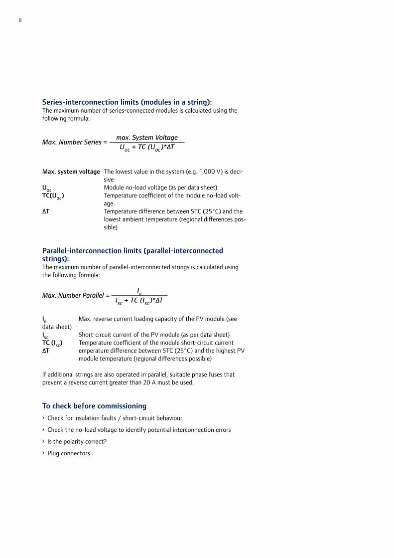
Series-interconnection limits (modules in a string):The maximum number of series-connected modules is calculated using the following formula:
Max. Number Series = max. System VoltageUOC + TC (UOC)*∆T
Max. system voltage The lowest value in the system (e.g. 1,000 V) is deci-sive
UOC Module no-load voltage (as per data sheet)TC(UOC) Temperature coefficient of the module no-load volt-
age∆T Temperature difference between STC (25°C) and the
lowest ambient temperature (regional differences pos-sible)
Parallel-interconnection limits (parallel-interconnected strings):The maximum number of parallel-interconnected strings is calculated using the following formula:
Max. Number Parallel = IRISC + TC (ISC)*∆T
IR Max. reverse current loading capacity of the PV module (see data sheet)ISC Short-circuit current of the PV module (as per data sheet)TC (ISC) Temperature coefficient of the module short-circuit current∆T emperature difference between STC (25°C) and the highest PV
module temperature (regional differences possible)
If additional strings are also operated in parallel, suitable phase fuses that prevent a reverse current greater than 20 A must be used.
To check before commissioning› Check for insulation faults / short-circuit behaviour
› Check the no-load voltage to identify potential interconnection errors
› Is the polarity correct?
› Plug connectors

9Installation and maintenance manual SOLON SOLfixx
2.3 Conditions for installation
You can use the SOLON SOLfixx installation system under the following conditions:
Operating location: Flat roof up to 5°, installation up to 10° upon request Installation: Roof installation Solar modules: SOLON Black 280/17, SOLON Blue 270/17 Module orientation: horizontal Install the units on fire-resistant roofing only.
Warning!The installation of the photovoltaic system must be carried out within the roof’s load-bearing reserves only. It is to be noted that weather conditions (wind/snow load) will result in excessive weight and uplift forces. Check the stability of the roof under these loads with a statistical analysis (DIN 1055-4 wind loads, DIN 1055-5, snow and ice loads).
2.4 Structural calculations
SOLfixx racks are generally installed in a group using the rack feet.
Exceptions are specified in the implementation plan. Ensure that surface for individual and group rack installations is even prior to implementation.
There are three installation possibilities:
2.4.1 Ballasting
When ballasting, pay attention to the plan specifications and the rooftop structure, particularly the roof edges. It is necessary to ensure that the roof is designed to handle the additional load.
If it is necessary to remove the existing roof material (gravel, concrete slabs) in order to put it into the troughs of the racks later, the material, up to the separating layer, must be removed and handled extremely carefully.
The installation instructions must be observed when filling the troughs. The maximum filling height of the troughs is 7.5 cm.
Due to the ballasting of the racks, a maximum distributed load of 1.00 kN/m² (100 kg/m²) is possible. For example, if the trough contains 7.5 cm of gravel (18 kN/m³), nine 30 x 30 x 3 cm concrete slabs and four 30 x 30 x 6 concrete slabs.
Reference and check values for filling a SOLfixx rack:
7.5 cm gravel (18 kN/m³) in two substructures and the weight of the SOLfixx . . . . . . . . . . . . . . . . . . . . . . gk = 0.730 kN/m²
5.0 cm gravel (18 kN/m³) in two substructures and the weight of the SOLfixx . . . . . . . . . . . . . . . . . . . . . . gk = 0.525 kN/m²
9 30 x 30 x 3.0 concrete slabs (6.5 kg each) . . . . . . . . gk = 0.189 kN/m² 4 30 x 30 x 6.0 concrete slabs (13 kg each) . . . . . . . . gk = 0.170 kN/m²

10
2.4.2 Anchoring
Use galvanized or stainless steel ropes with a diameter of 6 mm. Select turn-buckles and thimbles of the same material quality.
The position of the anchoring cables and the structural connection is available in the planning documents. Do not make the connections without a basis for planning. Contact SOLON in case of discrepancies. Connections are usually made to load-bearing attics (solid); additional vertical connections on the inside of the roof are possible. Plan and install the SOLfixx racks keeping their anchoring in mind.
Anchoring cables are always used on one level and are preloaded against verti-cal sagging (temperature expansion summer/winter).
2.4.3 Welding/bonding
You have to ensure that the roof covering is suitable for welding/bonding. The connection system must be approved by SOLON.The anchoring of the feet must be exactly planned with the position of the racks in the system axes.The maximum tensile forces (intersection point of four racks) in the case of bonding are Vk = 1.80 kN, Vk = 1.80 kN for welding.
2.5 Delivery
The modules are supplied on pallets with 14 modules per pallet.
The substructures and additional system components are supplied on pallets with 35 mounting racks per pallet.
Check order for completeness upon receipt of the goods based on the en-closed delivery note. SOLON SE is not liable for expenses and warranty in case of subsequent deliveries if you do not discover that material is missing until installation.
Check the goods visually for external damage.Contact your dealer in case of damage. Use the assembly instruction to familiarize yourself with the components of the flat roof system and their use before you start the installation.
11Installation and maintenance manual SOLON SOLfixx
3 Installing SOLON SOLfixx
Danger!Observe the safety guidelines for working on roofs.
In order to speed up installation as much as possible, SOLON recommends di-viding the installation process into the mechanical and electrical components. The individual assembly steps differ depending on the method by which the SOLON SOLfixx will be mounted on the roof:
Ballasting – standard Anchoring – when ballasting is not possible for structural reasons Bonding / Welding – when ballasting is not possible for structural reasons
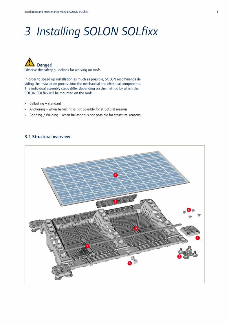
3.1 Structural overview
1
2
3
7
4
5
8
6

12
Item no.
1
2
3
4
5
6
7
Name
Module
Base plate
Substructure
Cover plate
Locking pin
Wind deflector
Cable duct cover
Description
SOLON Black 280/17 and SOLON Blue 270/17– Dimensions (L x W x H):
1,973 x 993 x 5.3 mm– 6 rails on the back made of glass fiber
reinforced plastic (polyamide – PA)
For connection of up to four substructures– Shaped so that it engages in four neighboring
corners of the substructure regardless of the orientation
– Dimensions (L x W x H): 255 x 255 x 74 mm
Substructure for mounting of modules on flat roofs– Polypropylene (PP)– Dimensions (L x W x H):
2,100 x 1,430 x 258 mm– Tilt: 10°
To lock up to four substructures connected with the base plate– The anchoring cable can be installed on two
levels– Dimensions (L x W x H):
235 x 235 x 35 mm
Prevents cover plate from loosening from base plate– Cover plate can only be reinstalled when the
locking pin has been removed– Dimensions:
Diameter 44 mm, height 25 mm
The wind deflector deflects or redirects wind loads– Its geometry also provides venting of the module– Dimensions (L x W x H): 824 x 198 x 28 mm
The cable duct cover is shaped so that it covers the cable ducts in the substructure– You can easily slide the covers into the negative
shapes provided in the substructure– Dimensions (L x W x H):
long: 1,050 x 50.5 x 2 mm short: 150 x 50.5 x 2 mm
13Installation and maintenance manual SOLON SOLfixx
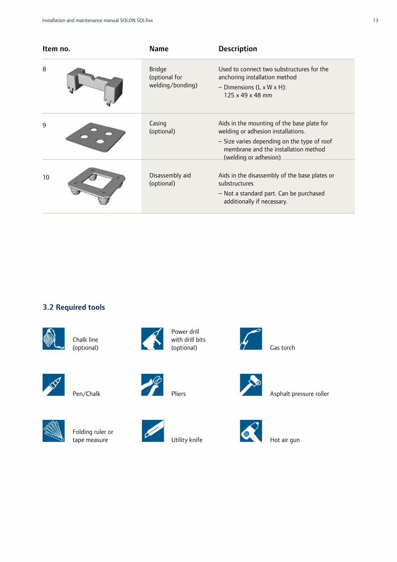
Description
Used to connect two substructures for the anchoring installation method– Dimensions (L x W x H):
125 x 49 x 48 mm
Aids in the mounting of the base plate for welding or adhesion installations. – Size varies depending on the type of roof
membrane and the installation method (welding or adhesion)
Aids in the disassembly of the base plates or substructures– Not a standard part. Can be purchased
additionally if necessary.
Item no.
8
9
10
Name
Bridge(optional for welding/bonding)
Casing (optional)
Disassembly aid (optional)
3.2 Required tools
Chalk line (optional)
Pen/Chalk
Folding ruler or tape measure
Power drill with drill bits (optional)
Pliers
Utility knife
Gas torch
Asphalt pressure roller
Hot air gun

14
3.3 Installation by means of ballasting
You do not need any tools when you install the modules by means of ballast-ing. The installer applies the ballasting individually.
1. Remove severe contamination from the roof cladding.
Caution!Especially small stones and similar objects must be removed from the surface as they can destroy the roof cladding when you install the SOLON SOLfixx system.
2. Mark the positions of the substructures on the roof (optional).
3. Place four base plates (2) each on the roof cladding, starting with the outer edge of what is to become the PV array. For a more accurate positioning of the base plates, use one SOLON SOLfixx substructure (3) as assembly aid.
2
2
2
3

15Installation and maintenance manual SOLON SOLfixx
4. Place all four corners of the substructure (3) on the mounting plates (2) so that the mounting plate fits into the appropriate elongated holes of the substructure. Ensure that the mounting plates are centered in the elongated holes of the substructure.
5. Use one SOLON SOLfixx substructure (3) as assembly aid to position the two additional base plates (2) on the side of the first substructure and attach another substructure (3) based on the previous steps.
6. Repeat the steps until all substructures (3) have been attached.
2
2
2
3
2
2
3
3
16
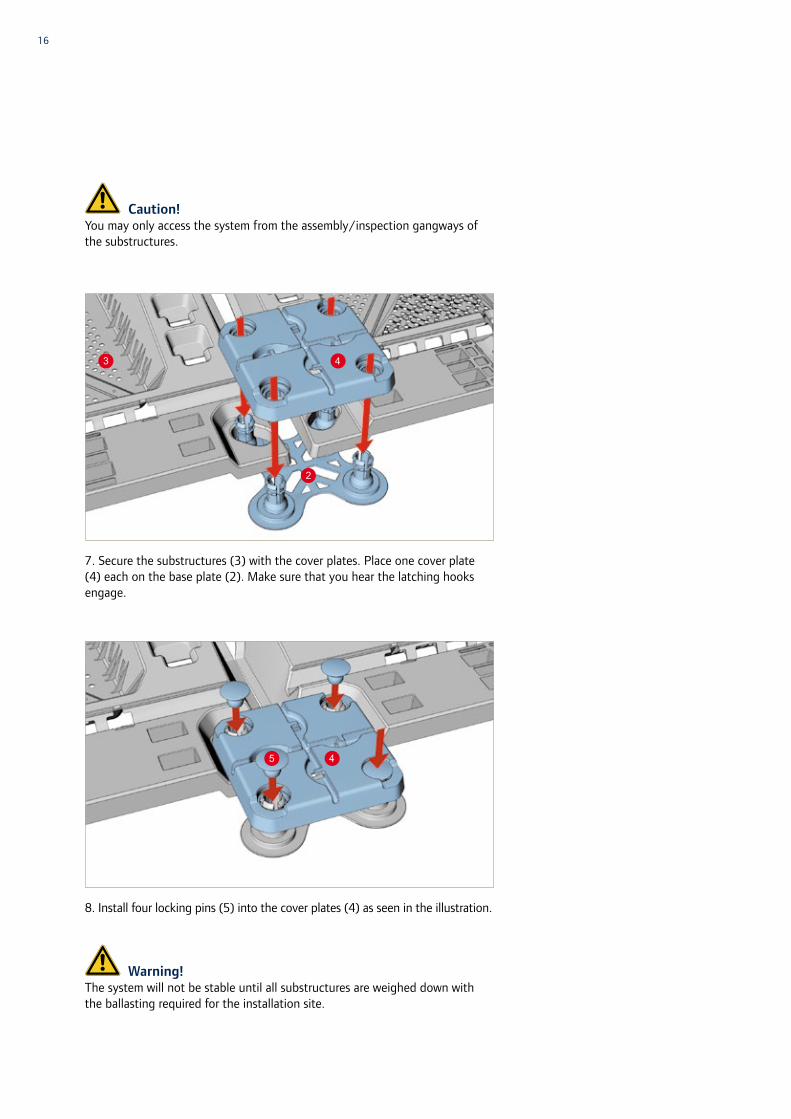
Caution!You may only access the system from the assembly/inspection gangways of the substructures.
7. Secure the substructures (3) with the cover plates. Place one cover plate (4) each on the base plate (2). Make sure that you hear the latching hooks engage.
8. Install four locking pins (5) into the cover plates (4) as seen in the illustration.
Warning!The system will not be stable until all substructures are weighed down with the ballasting required for the installation site.
3
2
4
45
17Installation and maintenance manual SOLON SOLfixx
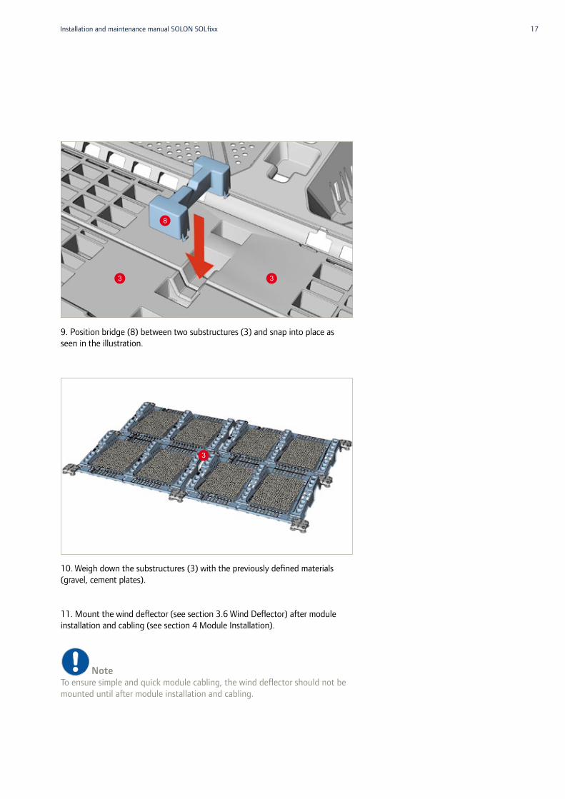
9. Position bridge (8) between two substructures (3) and snap into place as seen in the illustration.
10. Weigh down the substructures (3) with the previously defined materials (gravel, cement plates).
11. Mount the wind deflector (see section 3.6 Wind Deflector) after module installation and cabling (see section 4 Module Installation).
NoteTo ensure simple and quick module cabling, the wind deflector should not be mounted until after module installation and cabling.
33
8
3

18
3.4 Installation by means of anchoring
You can use installation by means of anchoring as an alternative if the roof should not have sufficient load-carrying reserves for ballasting. You can also use anchoring in combination with ballasting.
Anchoring of the steel rope depends on the material of the building. You can fasten the steel rope in the attic or anchors in the roof surface. Make sure you clarify the static of the anchoring points beforehand.
NoteThe required tools depend on the different options for fastening the anchoring cable to the roof (e.g. in the attic or in a concrete roof) and must be adapted for each project.
1. Remove severe contamination from the roof cladding.
Caution!Especially small stones and similar objects must be removed from the surface as they can destroy the roof cladding when you install the SOLON SOLfixx system.
2. Mark the positions of the substructures on the roof (optional). You can also work with a plumb line or direct measurement.

19Installation and maintenance manual SOLON SOLfixx
3. Position groups of four base plates (2) accordingly on the roof cladding, starting with the outer edge of what is to become the PV array. For a more accurate positioning of the base plates, use one SOLON SOLfixx substructure (3) as assembly aid.
4. Place all four corners of the substructure (3) on the mounting plates (2) so that the mounting plate fits into the appropriate elongated holes of the substructure. Ensure that the mounting plates are centered in the elongated holes of the substructure.
2
2
2
3
2
2
2
3

20
5. Use one SOLON SOLfixx substructure (3) as assembly aid to place two additional base plates (2) on the side of the first substructure and insert another substructure (3) based on the previous steps.
6. Repeat the steps until all substructures (3) have been applied.
Caution!You may only access the system from the assembly/inspection gangways of the substructures.
2
2
3
3
21Installation and maintenance manual SOLON SOLfixx
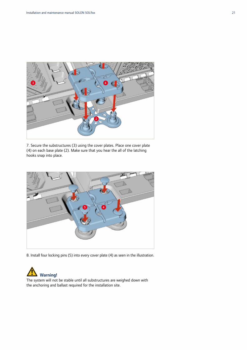
7. Secure the substructures (3) using the cover plates. Place one cover plate (4) on each base plate (2). Make sure that you hear the all of the latching hooks snap into place.
8. Install four locking pins (5) into every cover plate (4) as seen in the illustration.
Warning!The system will not be stable until all substructures are weighed down with the anchoring and ballast required for the installation site.
3
2
4
45

22
9. Position bridge (8) between two substructures (3) and engage as seen in the illustration.
10. Insert wire ropes (6 mm diameter) in cover plates (4) …
… and position under pads integrated in the cover plate (4).
33
8
4
4
4
4
4
4
23Installation and maintenance manual SOLON SOLfixx
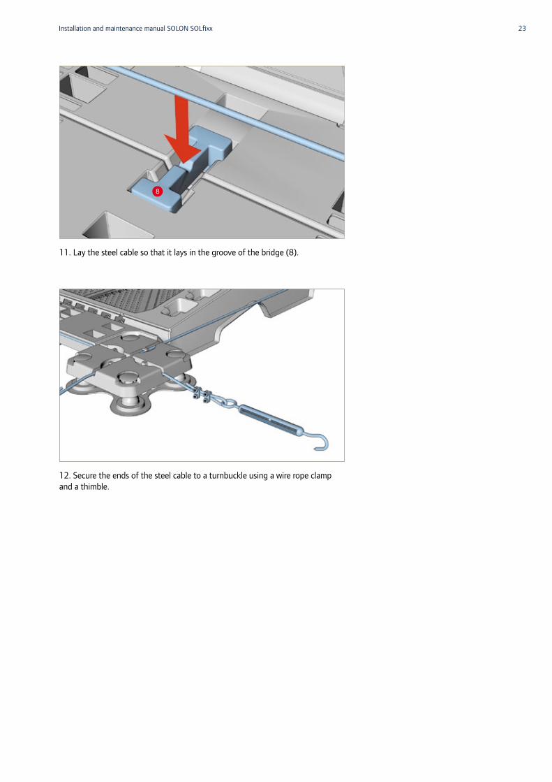
11. Lay the steel cable so that it lays in the groove of the bridge (8).
12. Secure the ends of the steel cable to a turnbuckle using a wire rope clamp and a thimble.
8
24
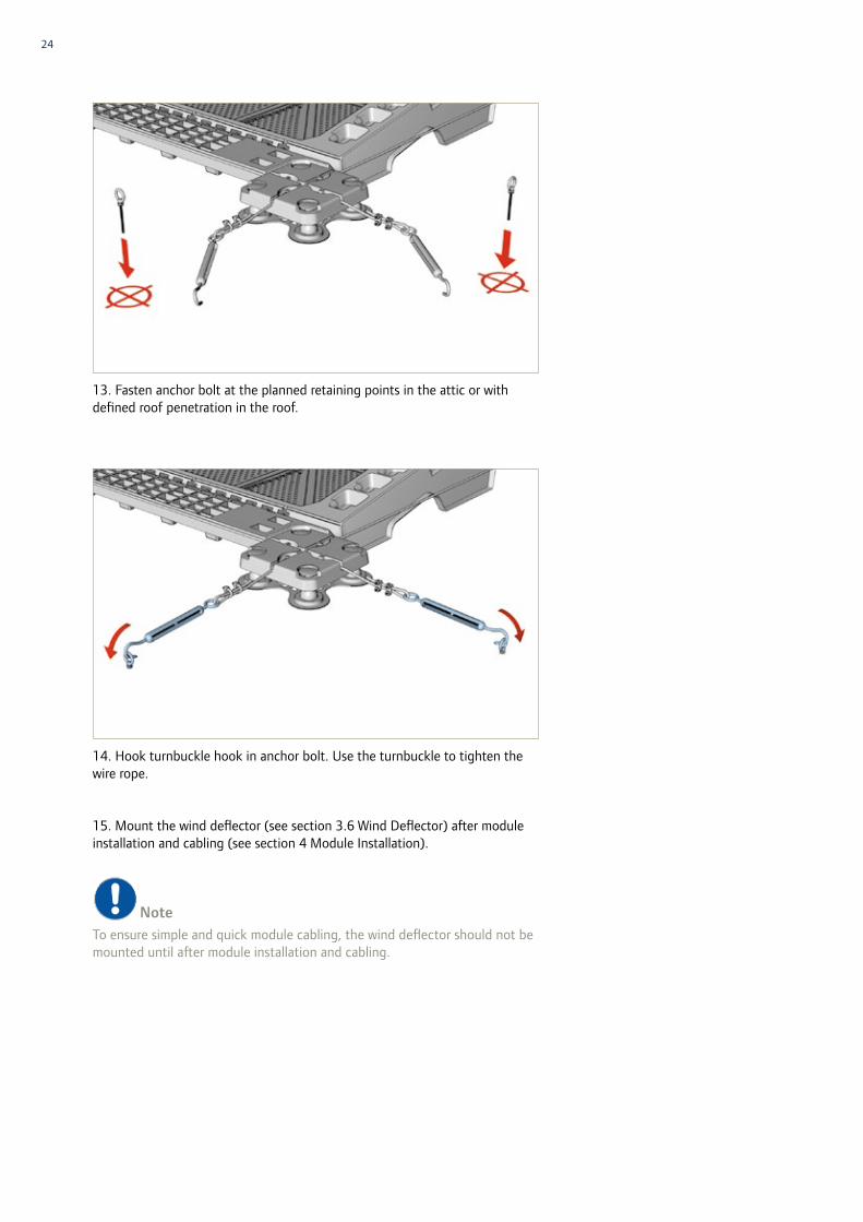
13. Fasten anchor bolt at the planned retaining points in the attic or with defined roof penetration in the roof.
14. Hook turnbuckle hook in anchor bolt. Use the turnbuckle to tighten the wire rope.
15. Mount the wind deflector (see section 3.6 Wind Deflector) after module installation and cabling (see section 4 Module Installation).
NoteTo ensure simple and quick module cabling, the wind deflector should not be mounted until after module installation and cabling.
25Installation and maintenance manual SOLON SOLfixx
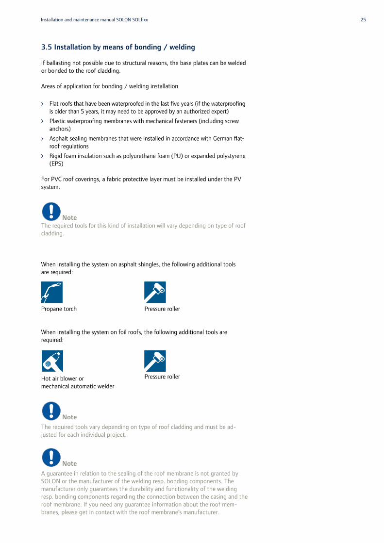
3.5 Installation by means of bonding / welding
If ballasting not possible due to structural reasons, the base plates can be welded or bonded to the roof cladding.
Areas of application for bonding / welding installation
Flat roofs that have been waterproofed in the last five years (if the waterproofing is older than 5 years, it may need to be approved by an authorized expert)
Plastic waterproofing membranes with mechanical fasteners (including screw anchors)
Asphalt sealing membranes that were installed in accordance with German flat-roof regulations
Rigid foam insulation such as polyurethane foam (PU) or expanded polystyrene (EPS)
For PVC roof coverings, a fabric protective layer must be installed under the PV system.
NoteThe required tools for this kind of installation will vary depending on type of roof cladding.
When installing the system on asphalt shingles, the following additional tools are required:
Propane torch
When installing the system on foil roofs, the following additional tools are required:
Hot air blower or mechanical automatic welder
NoteThe required tools vary depending on type of roof cladding and must be ad-justed for each individual project.
NoteA guarantee in relation to the sealing of the roof membrane is not granted by SOLON or the manufacturer of the welding resp. bonding components. The manufacturer only guarantees the durability and functionality of the welding resp. bonding components regarding the connection between the casing and the roof membrane. If you need any guarantee information about the roof mem-branes, please get in contact with the roof membrane’s manufacturer.
Pressure roller
Pressure roller

26
1. Remove severe contamination from the roof cladding.
Caution!Especially small stones and similar objects must be removed from the surface as they can destroy the roof cladding when you install the SOLON SOLfixx system.
2. Mark the positions of the substructures on the roof (optional). You can also work with a plumb line or direct measurement.
3. Place four base plates (2) each on the roof cladding, starting with the outer edge of what is to become the PV array. For a more accurate positioning of the base plates, use one SOLON SOLfixx substructure (3) as assembly aid.
2
2
2
3
27Installation and maintenance manual SOLON SOLfixx
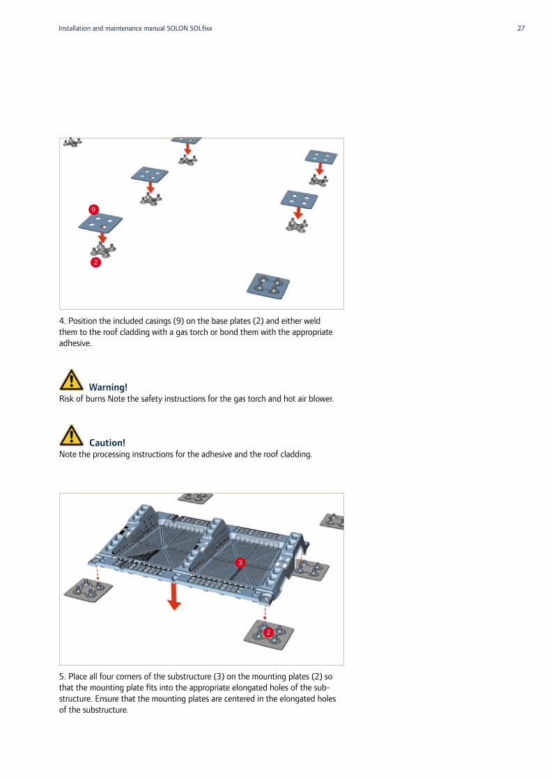
4. Position the included casings (9) on the base plates (2) and either weld them to the roof cladding with a gas torch or bond them with the appropriate adhesive.
Warning!Risk of burns Note the safety instructions for the gas torch and hot air blower.
Caution!Note the processing instructions for the adhesive and the roof cladding.
5. Place all four corners of the substructure (3) on the mounting plates (2) so that the mounting plate fits into the appropriate elongated holes of the sub-structure. Ensure that the mounting plates are centered in the elongated holes of the substructure.
2
9
3
2

28
6. Use one SOLON SOLfixx substructure (3) as assembly aid to place two additional base plates (2) on the side of the first substructure and insert another substructure (3) based on the previous steps.
7. Repeat the steps until all substructures (3) have been applied.
Caution!You may only access the system from the assembly/inspection gangways of the substructures.
3
2
3
29Installation and maintenance manual SOLON SOLfixx
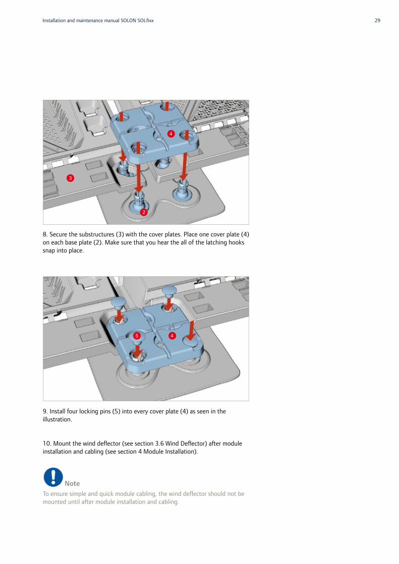
8. Secure the substructures (3) with the cover plates. Place one cover plate (4) on each base plate (2). Make sure that you hear the all of the latching hooks snap into place.
9. Install four locking pins (5) into every cover plate (4) as seen in the illustration.
10. Mount the wind deflector (see section 3.6 Wind Deflector) after module installation and cabling (see section 4 Module Installation).
NoteTo ensure simple and quick module cabling, the wind deflector should not be mounted until after module installation and cabling.
3
4
2
5 4

30
3.6 Wind deflector
The wind deflector deflects or redirects wind loads. The geometry of the wind deflector and the substructure also provide ventilation of the module.
NoteThe wind deflector should not be mounted until after module installation and cabling.
1. Install two wind deflectors (6) each per substructure (3). To do so, insert the wind deflector as shown in the illustration in the corresponding receptacles on the high long side of the substructure.
Installation of the substructure is now complete.
6 6
3

31Installation and maintenance manual SOLON SOLfixx
4 Module installation
Danger!Observe the safety guidelines for working on roofs.
Danger!Observe the safety guidelines for working with direct current. The modules are always live when they are exposed to sunlight.
Caution!You may only access the system from the assembly/inspection gangways of the substructures.
4.1 Installing the module
Module installation takes place after mounting and ballasting/anchoring and/or adhesion/welding.
Caution!It is not possible for one person alone to install a module. At least two persons are required for this step.
NoteThe substructures are only to be used for the installation of the Module SOLON Black 280/17 or SOLON Blue 270/17 modules. The frameless modules are delivered ready-to-use with six rails on the back of each module which allow it to be secured onto the substructures.
Caution!The solar cables must be laid in the appropriate cable duct outputs in a north/south direction before the final step when the modules are snapped into the substructures.
32
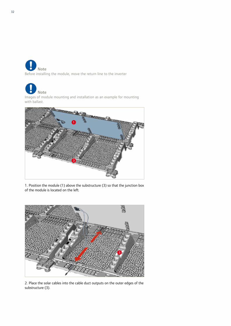
NoteBefore installing the module, move the return line to the inverter
NoteImages of module mounting and installation as an example for mounting with ballast.
1. Position the module (1) above the substructure (3) so that the junction box of the module is located on the left.
2. Place the solar cables into the cable duct outputs on the outer edges of the substructure (3).
1
3
3
33Installation and maintenance manual SOLON SOLfixx
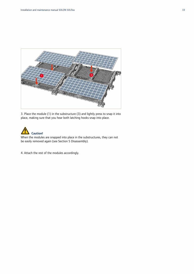
3. Place the module (1) in the substructure (3) and lightly press to snap it into place, making sure that you hear both latching hooks snap into place.
Caution!When the modules are snapped into place in the substructures, they can not be easily removed again (see Section 5 Disassembly).
4. Attach the rest of the modules accordingly.
1 3

34
4.2 Electrical installation
Warning!Avoid large conductor loops when routing the cables to prevent coupling of overvoltages through lightning.
Warning!Use only UV-resistant cables intended for this purpose, known as solar cables, for cabling of the photovoltaic system.
1. Cabling must take place according to the wiring plan. Place the cables into the cable duct outputs on the outer edges of the substructure (3) in the process.
2. Slide the cable duct covers (7) into the counterparts intended for this pur-pose of the substructure (3). The wind deflector is then installed (see section 3.6).
3
3
77

35Installation and maintenance manual SOLON SOLfixx
4.2.1 Protection against lightning and overvoltage
Warning!Solon Energy GmbH acknowledges that the photovoltaic system‘s protection against lightning and overvoltage must be in accordance with the current specifi-cations of the following standards and regulations, as well as those of the specific countries in which the system will be used. Please gather more detailed informa-tion about the local standards and regulations of the country in question.
Existing lightning protectionIf there is already external lightning protection in place, the photovoltaic system must be integrated into it. If there is an existing lightning protection system on the building and the PV generator is not in the protection range of the arrester, all metal parts of the PV generator must be incorporated into the external lightning protec-tion, so that the lightning protection class of the building is maintained. The dis-tance between the photovoltaic system and the arrester must be taken into account (DIN EN 62305-3). This includes, among others, the modules, all cables and wiring (including the cables and wiring inside of the building), converters, collection boxes, and windows. If you are unsure, please consult a lightning protection designer or a lightning protection installer. To avoid coupling, SOLON Energy GmbH recommends that the cables and wiring be laid in metal cable channels. Both ends of these chan-nels are to be included in the equipotential bonding.
It is recommended that the cables be laid outside of the building’s exterior. If there is a lightning protection system already in place, the equipotential bonding is to be performed with 6 mm² copper or metal with an equal electrical conductance. The standard recommends half of the cross-section of the largest protective ground con-ductor in the system. Furthermore, the standard recommends that the appropriate overvoltage protection devices be installed.
To avoid a shadow being cast by the lightning rod onto the system, an adequate distance between the lightning rod, lightning conductor and the module should be maintained when possible. If an adjustment to the lightning protection system is necessary, the lightning protection designer for the system in place must be con-tacted.
No existing lightning protection systemSOLON Energy GmbH acknowledges that an external lightning protection system of lightning protection class 3 is only recommended for photovoltaic rooftop systems in DIN EN 62305.
SOLON Energy GmbH generally recommends that assembly systems, cable channels, and other components be incorporated into the equipotential bonding and that overvoltage protection devices be used. If there is no existing lightning protection system in place, equipotential bonding must be carried out with 16 mm² copper or metal with an equal electrical conductance and have the half cross section of the largest protective ground conductor in the system. If there is no lightning protection system, type 1 arresters (lightning current arresters) are to be used.
Caution!Equipotential bonding is necessary whenever transformerless inverters are used.
NoteIt is generally advisable to contact a lightning protection system designer.
36
Danger!Observe the safety guidelines for working on roofs.
Danger!Observe the safety guidelines for working with direct current. The modules always generate a voltage when they are exposed to light.
Caution!You may only access the system from the assembly/inspection gangways of the substructures.
Disassembly always takes place in the reverse order of installation. Any special considerations during disassembly are described in the following chapters.
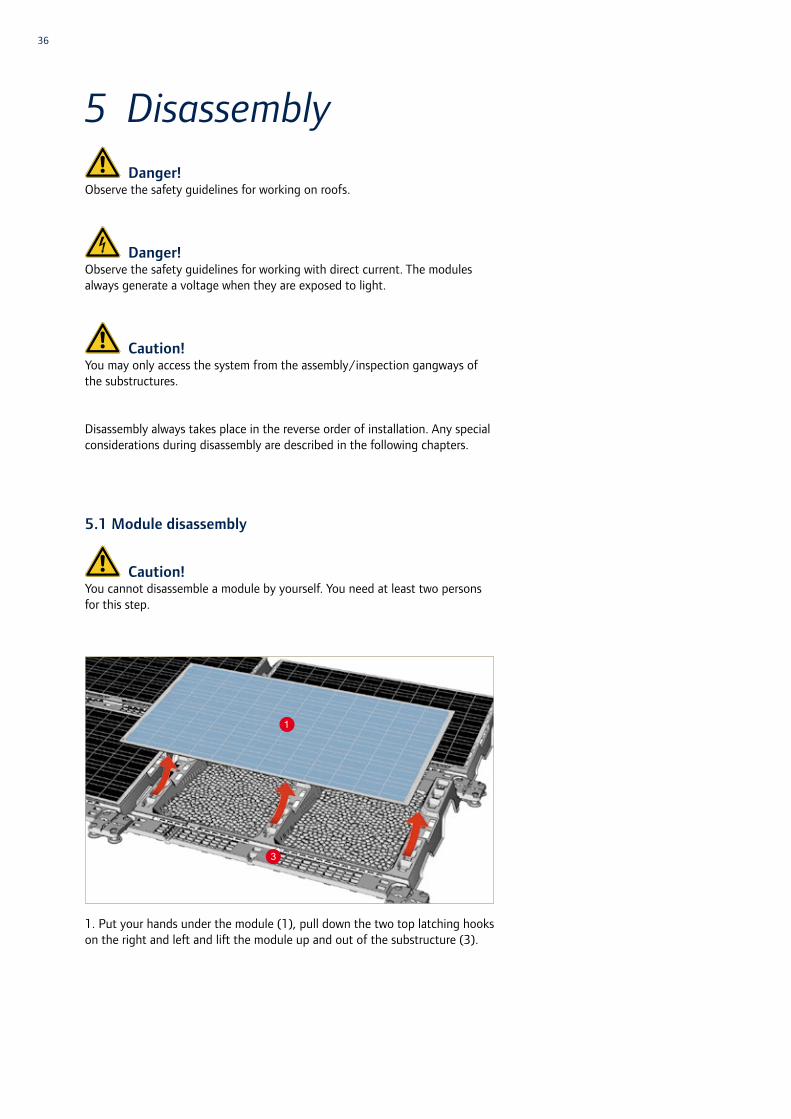
5.1 Module disassembly
Caution!You cannot disassemble a module by yourself. You need at least two persons for this step.
1. Put your hands under the module (1), pull down the two top latching hooks on the right and left and lift the module up and out of the substructure (3).
1
5 Disassembly
3

37Installation and maintenance manual SOLON SOLfixx
5.2 Substructure disassembly
1. If applicable, remove bridge (8) from the substructures (3).
2. Pull out / remove the locking pins (5) from the base plate (4) by hand or using a flat-head screwdriver.
5
5
4
5
8

38
3. Place the disassembly aid (10) on the cover plate (4) or expansion anchor of the base plate (2) to unlock the expansion anchors.
4. Remove the cover plate (4) with the disassembly aid (10).
5. Lift the substructure (3) from the base plates (2) and remove it.
10
4
2
10
4
32
2
2

39Installation and maintenance manual SOLON SOLfixx
6 Maintenance and Cleaning
The tilt of the SOLON modules makes it so that dust and dirt are generally adequately removed by rain. Snow also usually slides off of the SOLON modules on its own. If the modules become very dirty, they can be cleaned using lots of water at a maximum temperature of 40°C and a gentle cleaning device, such as a sponge.
NoteUpon request, we are happy to recommend a commercial cleaning agent that we have found to perform exceptionally well at protecting against streaks and fingerprints in our internal tests.
Danger!Take note of and adhere to the safety information and warnings in the section “Safety information” during maintenance and cleaning. Maintenance and cleaning should be performed by trained professionals.
Caution!Never use abrasive cleansers, such as pad brushes, or objects with a degree of hardness < 5 when cleaning SOLON modules. “Low-E” roller brushes may only be used with a bristle diameter of < 0.15 mm. When using high-pressure clea-ners, keep a minimum distance of 50 cm from the surface to be sprayed and use water with a maximum temperature of 40°C.
Caution!Never use abrasive cleansers when cleaning SOLON modules. Use cleaning agents with a concentration of no more than 20% glass cleaner. A higher concentration could damage the module surface.
NoteCleaning the modules can marginally increase yield. This applies particularly to dirt caused by fallen leaves or bird droppings, which could lead to partial shading. On the other hand, yield decreases due to snow are negligible, since these take place during the seasons with the lowest yield anyway. The PV system should be maintained by trained professionals at fixed intervals (for example, every three years) as well. The following points should be checked in the process:– Security of the system anchoring on the roof– Functionality of the circuit breakers– Measurement of the string voltage and string currents– Integrity of the roof cladding
Caution!The legal regulations for the testing of PV systems without a safety circuit for inverter grid monitoring are to be observed.

40
7 Recycling and Disposal
SOLON modules consist of precious resources, such as glass, copper, tin, sili-con, aluminum, silver and lead. SOLON offers free module recycling to ensure an environmentally friendly and sustainable disposal of your modules.
After disassembly of your photovoltaic system, please get in touch with SO-LON in order to arrange the free module recycling.
You can dispose of the substructure of your photovoltaic system by contact-ing a suitable recycling company (e. g. recycling depots, scrap metal collection points).
Feel free to contact SOLON if you have any further questions.

41Installation and maintenance manual SOLON SOLfixx
The SOLON SOLfixx technical and mechanical specifications are available on the SOLON SOLfixx datasheet at www.solon.com
8 Appendix – Technical and Mechanical Specifications

42
SOLON Energy GmbHAm Studio 16 12489 Berlin · GermanyPhone +49 30 81879-0Fax +49 30 81879-9999E-Mail [email protected]
01/14


