30
INSTALLATION AND Maintenance manual INDIRECT HIU DHW + HEATING DIRECT HIU DHW + HEATING 1 2 E&OE (09/20)

INSTALLATION AND Maintenance manualINDIRECT HIU DHW + HEATINGDIRECT HIU DHW + HEATING
12
E&OE (09/20)

INTRODUCTIONINTRODUCTION
SAFETY INSTRUCTIONS• Manual Handling • Installation Safety Guidance • Commissioning & Maintenance Safety Guidance
INDIRECT HIU TECHNICAL SPECIFICATION • Product Dimensions • Technical Specification • Component Parts List • Hydraulic Schematic
DIRECT HIU TECHNICAL SPECIFICATION • Product Dimensions • Technical Specification • Components Parts List • Hydraulic Schematic
DOMESTIC HOT WATER CHARACTERISTICS
ACCESSORIES
ELECTRICAL WIRING SCHEMATIC
INSTALLATION INSTRUCTIONS• Unpacking • Fitting Location• Wall Mounting• Hydraulic Connections• Electrical Connections
COMMISSIONING THE SYSTEM• Flushing the Heat Network• Cleansing the System Using the Flushing Bypass• Filling the Primary and DHW Circuit• Filling the Space Heating Circuit• Pre-commissioning Checklist• Commissioning Checklist
FAULT FINDING
REPLACEMENT PARTS
MAINTENANCE
SERVICE RECORD
PRODUCT WARRANTY
YGHP Indirect and Direct Heat Interface Units, (HIU), are specifically designed for the provision of domestic hot water, (DHW), and heating for use in situations where heat is provided to a dwelling from an external, centralised source.
The YGHP HIU should be used exclusively for radiator/floor heating and domestic hot water, (DHW), preparation. Any other use of the product will be considered as improper and will result in the voidance of any product warranty and the end of YGHP’s liability against any fault or damage caused.
YGHP pride ourselves on the quality of our products. Our HIUs are produced in an ISO 9001:2015, ISO 14001:2015 and OHSAS 18001 compliant environment so you can be sure our products have been manufactured in a conscientious and sustainable way.
It is important that the design, installation and commissioning It is important that the design, installation and commissioning of any system is done in accordance with best practice. YGHP of any system is done in accordance with best practice. YGHP recommend considering the below standards before specifying recommend considering the below standards before specifying and installing any HIU.and installing any HIU.
Whilst every effort has been made to ensure the information contained within these instructions is accurate, YGHP assumes no responsibility or liability for any errors of omissions.
Detailed recommendations are contained in the following British Standard Codes of Practice:
BS EN 12828:2012+A1:2014BS EN 12828:2012+A1:2014Heating systems in buildings. Design for water based-heating systems.
BS EN 13831:2007 BS EN 13831:2007 Closed expansion vessels with built in diaphragm for installation in water.
BS 7593:2019BS 7593:2019Code of Practice for the preparation, commissioning and maintenance of domestic central heating and cooling water systems.
BS EN 14336:2004BS EN 14336:2004 Heating Systems in buildings: Installation and commissioning of water-based heating systems.
BSRIA GUIDE BG 50/2013BSRIA GUIDE BG 50/2013Water Treatment for Closed Heating & Cooling Systems
BSRIA GUIDE BG 29/2020BSRIA GUIDE BG 29/2020Pre-Commissioning Cleaning of Pipework Systems.
It is the responsibility of the installer to ensure the YGHP HIU is installed to the appropriate Building Regulations.Either;
The Building RegulationsThe Building Regulations (Scotland)Building Regulations (Northern Ireland)Building Regulations (Wales) The Water Fittings Regulations Water byelaws in ScotlandThe Current I.E.E. Wiring Regulations
Where no specific guidance has been given, installers should refer to the relevant British Standard Code of Practice.
445
6789
10111213
14
15
16
1718181919
202021222324
25
26
27
28
29

4
SAFETY INSTRUCTIONSSAFETY INSTRUCTIONS
These instructions should be read and understood fully before attempting to install the product. FAILURE TO DO SO CAN RESULT IN PERSONAL INJURY, DAMAGE TO PROPERTY OR THE PRODUCT. FAILURE TO DO SO CAN RESULT IN PERSONAL INJURY, DAMAGE TO PROPERTY OR THE PRODUCT. The YGHP HIU should be installed, commissioned and maintained by a relevantly qualified, competent engineer and in accord-ance to the applicable national or local legislation.
MANUAL HANDLINGMANUAL HANDLING
The YGHP HIU may need two or more people to move it to the installation location, remove it from it’s packaging and hang the product on it’s mounting brackets. Installers should be aware of the risk of injury due to poor manual handling practices and be mindful to minimise their risk. Detailed guidance on best manual handling practice can be found on the Health & Safety Execu-tives website.
INSTALLATION SAFETY GUIDANCEINSTALLATION SAFETY GUIDANCE
• The installation, commissioning, and maintenance of any YGHP HIU must be carried out by a qualified, competent and authorised engineer.
• If the product is not installed, commissioned, and maintained in accordance with the instructions provided in this manual, it may operate outside of the manufacturers specification and present a risk of harm to the end user.
• The system should be installed in a frost-free room.
• The temperature and humidity of the final installation site should not exceed 50 °C and 60% respectively.
• Under no circumstances should these values, or any other values, specified in this manual be exceeded.
• The HIU should be easily accessible for maintenance, servicing and in case of an emergency.
• Before the system is filled, it is the installing engineer’s responsibility to ensure all internal unions of the HIU are tight.
• Primary and secondary pipe work should be flushed according to BSRIA guidance document BG 29/2020 and BG 50/2013.
• Failure to flush primary and secondary pipe work effectively may lead to debris entering the HIU, resulting in either a drop in performance, or its complete failure.
• Failure of the unit due to poor water quality is not covered by warranty.
• Any retrospective action taken by YGHP to resolve issues relating to water quality will be chargeable.
• Only use replacement parts supplied from YGHP. Failure to do so may result in the failure of the product or personal injury.

5
COMMISSIONING & MAINTENANCE SAFETY GUIDANCECOMMISSIONING & MAINTENANCE SAFETY GUIDANCE
WARNING OF ELECTRIC SHOCK WARNING OF ELECTRIC SHOCK
The installation, commissioning, and maintenance of the electrical connections to and from the HIU must be performed by a competent, qualified engineer.
• The unit must always be earthed before it is connected to the electric supply.
• If the unit must be removed, always disconnect the earth connection after after disconnecting the electric supply.
• Check that the earth connection has been made to the highest standard compliant to local and/or national legislation.
• The electrical installation of this product should be done so by following the instructions provided and in compliance with any local and/or national standards.
• Modifications to the electrical system of the HIU without the formal, written consent of the manufacturer are specifically prohibited.
• Any deviation to the unit from this instruction will void the warranty.
RISK OF FATAL OR SERIOUS INJURYRISK OF FATAL OR SERIOUS INJURY
When operational, the HIU is connected to mains voltage.
• Do not touch electrical components with wet or damp body parts.
• Do not pull on electrical lines.
• Do not touch live parts
• The system should be electrically disconnected for service, repair and maintenance.
• All repairs must be performed by a competent, authorised engineer.
WARNING OF HIGH PRESSURE AND HIGH TEMPERATUREWARNING OF HIGH PRESSURE AND HIGH TEMPERATURE
• The maximum operating temperature and pressure of the HIU are 90 °C and 16 bar respectively.
• Some surfaces and components within, and external to, the HIU can become hot.
• Do not touch hot surfaces.
• Hot surfaces can cause skin burns.
• If you must touch or be in close proximity to the HIU, check the surface temperature of the HIU with suitable equipment before touching any surface or part of the system.

6
YGHP INDIRECT HIU DIMENSIONSYGHP INDIRECT HIU DIMENSIONS
600
111
540
124
110
6585 390
128
37
68 65 65 65 277

7
YGHP INDIRECT HIU TECHNICAL SPECIFICATIONYGHP INDIRECT HIU TECHNICAL SPECIFICATION
Domestic Hot Water (DHW)Domestic Hot Water (DHW)
Primary SidePrimary Side
External ConnectionsExternal Connections
Electrical ConnectionsElectrical Connections
Radiators 40-90 oCUFH 20-50 oC
Secondary circuit max.pressure 10 BarSecondary circuit max. operating pressure 2.5 Bar
Max. pressure loss in primary 40 kPaMax. pressure loss in secondary 40 kPa
Pump Wilo Para 15/7Safety relief valve setting 3 Bar
Expansion vessel 8 LitresHeating control circuit (room stat) 240V - MAINS POWERED
Set point 20-70 oCMax. pressure 10 Bar
Max. operating pressure 4 BarDHW flow rate* 12/18/23 L/min
DHW PHE capacity 33-120 kW
Max. working pressure 10 BarMax working temperature 90 oC
Fluid medium WaterDifferential pressure control valve factory setting 40 kPa
Maximum differential pressure 150 kPa
Primary flow 3/4” BSP
Primary return 3/4” BSPSecondary flow 3/4” BSP
Secondary return 3/4” BSPCold water inlet 3/4” BSP
DHW outlet 3/4” BSP
Main voltage 230 V AC + 10%Power frequency 50-60 hzOperating voltage 5 V AC + 10%
Input 0.15 - 3 WProtection IP44

8
1. Plate Heat Exchange Cover 11. Flushing By-Pass Valve Assembly
2. Manual Air Vent 12. Electrical Junction Box (model specific)
3. Plate Heat Exchange Cover 13. Stool Piece for Heat Meter
4. Circulating Pump 14. Y-Pattern Strainer
5. Heating Plate Heat Exchanger 15. Water Hammer Shock Arrestor Vessel
6. DHW Plate Heat Exchanger 16. Differential Pressure Balancing Valve
7. Safety Relief Valve 17. Thermostatic Control Head for Radiators or UFH
8. Temperature & Pressure Gauge 18. Thermal Actuator
9. Cold Water Circuit and Heating Drain Valves 19. Thermostatic Control Head for DHW
10. Primary Isolating Ball Valves 20. Heating Expansion Vessel
YGHP INDIRECT HIU COMPONENT PART LISTYGHP INDIRECT HIU COMPONENT PART LIST
Key to Symbols SchematicKey to Symbols Schematic1. Domestic Hot Water Outlet
2. Domestic Cold Water Supply
3. Primary Return
4. Primary Flow
5. Secondary Flow
6. Secondary Return
104
1
5
2
6
3
13
2
16
5
11
14
3
17
6
12
1
15
4
18
7 19
8
9
2020
G3/4”
Please pay attention to the stickers on the first fix rail of the unit which show the inlets, outlets and direction of flow
1 42 53 6

9
YGHP INDIRECT HIU SYSTEM SCHEMATICYGHP INDIRECT HIU SYSTEM SCHEMATIC
INSTALLATION WITH RADIATORSINSTALLATION WITH RADIATORS
INSTALLATION WITH UFHINSTALLATION WITH UFH
COMPONENT KEY FOR SCHEMATICSCOMPONENT KEY FOR SCHEMATICS
2Optio
n
T
TA
T
1
TM
a
b
OptionOption
c
d
e
f
HIU Radiator Indirect System
44.01.01.003
Product Number
a Heating Water Supplyb Heating Water Returnc Apartment Heating Water Supplyd Apartment Heating Water Returne Domestic Hot Water Outletf Domestic Cold Water Supply
N L N L
TA
TM
T Fittings Shutoff valfPump
Temp.Sensor Thermomanometer
SafetyValve Expansion
Manual airvent valve
HeatingExchangers
Strainer
Fillingdraing
Cablejunction
box
T
TADHW
Exchangers
1
Heatmeter
ThermalActuator
ThermostaticValve
Filling loop
N L N L
TAWater
Hammer
2
Option
Option By-pass
DpBalancing
Valve
T
ThermostaticValve
2Optio
n
a Heating Water Supplyb Heating Water Returnc Apartment Heating Water Supplyd Apartment Heating Water Returne Domestic Hot Water Outletf Domestic Cold Water Supply
T
TA
T
1
TM
a
b
Option
c
d
e
f
HIU Floor Heting Indirect System
44.01.01.004
Product Number
N L N L
TA
TM
T Fittings Shutoff valfPump
Temp.Sensor Thermomanometer
SafetyValve Expansion
Manual airvent valve
HeatingExchangers
Strainer
Fillingdraing
Cablejunction
box
T
TADHW
Exchangers
1
Heatmeter
ThermalActuator
ThermostaticValve
Filling loop
N L N L
TA
WaterHammer
2
Option
Option By-pass
DpBalancing
Valve
T
ThermostaticValve
Heating Water SupplyHeating Water ReturnApartment Heating Water SupplyApartment Heating Water ReturnDomestic Hot Water OutletDomestic Cold Water Outlet
Heating Water SupplyHeating Water ReturnApartment Heating Water SupplyApartment Heating Water ReturnDomestic Hot Water OutletDomestic Cold Water Outlet
abcdef
abcdef

10
YGHP DIRECT HIU DIMENSIONSYGHP DIRECT HIU DIMENSIONS
12
600
200
490
65656597 65 65 68

11
YGHP DIRECT HIU TECHNICAL SPECIFICATIONYGHP DIRECT HIU TECHNICAL SPECIFICATION
Domestic Hot Water (DHW)Domestic Hot Water (DHW)
Primary SidePrimary Side
External ConnectionsExternal Connections
Electrical ConnectionsElectrical Connections
Radiators 40-90 oCUFH 20-50 oC
Secondary circuit max.pressure 10 BarSecondary circuit max. operating pressure 3 Bar
Max. pressure loss in primary 40 kPaMax. pressure loss in secondary 40 kPa
Pump Wilo Para 15/7Safety relief valve setting 3 Bar
Expansion vessel 8 LitresHeating control circuit (room stat) 240V - MAINS POWERED
Set point 20-70 oCMax. pressure 10 Bar
Max. operating pressure 4 BarDHW flow rate* 12/18/23 L/min
DHW PHE capacity 33-120 kW
Primary flow 3/4” BSP
Primary return 3/4” BSPSecondary flow 3/4” BSP
Secondary return 3/4” BSPCold water inlet 3/4” BSP
DHW outlet 3/4” BSP
Main voltage 230 V AC + 10%Power frequency 50-60 hzOperating voltage 5 V AC + 10%
Input 0.15 - 3 WProtection IP44
Max. working pressure 10 BarMax working temperature 90 oC
Fluid medium WaterDifferential pressure control valve factory setting 40 kPa
Maximum differential pressure 150 kPa
12
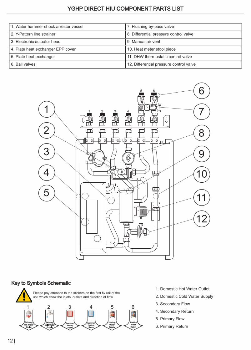
YGHP DIRECT HIU COMPONENT PARTS LISTYGHP DIRECT HIU COMPONENT PARTS LIST
1. Water hammer shock arrestor vessel 7. Flushing by-pass valve
2. Y-Pattern line strainer 8. Differential pressure control valve
3. Electronic actuator head 9. Manual air vent
4. Plate heat exchanger EPP cover 10. Heat meter stool piece
5. Plate heat exchanger 11. DHW thermostatic control valve
6. Ball valves 12. Differential pressure control valve
12
1
6
3
8
12
2
7
11
4
9
5
10
Key to Symbols SchematicKey to Symbols Schematic1. Domestic Hot Water Outlet
2. Domestic Cold Water Supply
3. Secondary Flow
4. Secondary Return
5. Primary Flow
6. Primary Return
Please pay attention to the stickers on the first fix rail of the unit which show the inlets, outlets and direction of flow
1 42 53 6
1 2 3 4
5 6

13
YGHP DIRECT HIU SYSTEM SCHEMATICYGHP DIRECT HIU SYSTEM SCHEMATIC
INSTALLATION WITH RADIATORS
INSTALLATION WITH UNDERFLOOR HEATING
COMPONENT KEY FOR SCHEMATICS
T
TA
2Optio
n
HIU Radiator direct System
44.01.01.001
Product Number
TM
T Fittings Shutoff valfPump
Temp.Sensor Thermomanometer
Manual airvent valve
Strainer
T
TAExchangers
1
HeatmeterThermalActuator
ThermostaticValve
WaterHammer
2
Option
1
2
Option By-passOption
3
4
Option
1 Heating Water Supply2 Heating Water Return3 Domestic Hot Water Outlet4 Domestic Cold Water Supply5 Apartment Heating Water Supply6 Apartment Heating Water Return6 5
DpBalancing
Valve
1 Heating Water Supply2 Heating Water Return3 Domestic Hot Water Outlet4 Domestic Cold Water Supply5 Apartment Heating Water Supply6 Apartment Heating Water Return
T
TA
2Optio
n
T
HIU Floor Heating direct System
44.01.01.002
Product Number
TM
T Fittings Shutoff valfPump
Temp.Sensor Thermomanometer
Manual airvent valve
Strainer
Cablejunction
box
T
TAExchangers
1
HeatmeterThermalActuator
ThermostaticValve
N L N L
TA
WaterHammer
2
Option
1
2
Option By-passOption
3
4
Option
TM 1 Heating Water Supply2 Heating Water Return3 Domestic Hot Water Outlet4 Domestic Cold Water Supply5 Apartment Heating Water Supply6 Apartment Heating Water Return6 5
DpBalancing
Valve

14
12
DOMESTIC HOT WATER FLOW CHARACTERISTICS - DIRECT & INDIRECTDOMESTIC HOT WATER FLOW CHARACTERISTICS - DIRECT & INDIRECT
Heating of Domestic Hot Water 10 to 50oC - Capacity 2
Heating of Domestic Hot Water 10 to 50oC - Capacity 3
Heating of Domestic Hot Water 10 to 50oC - Capacity 1
Primary Heating Flowrate [l/s]
Dom
estic
Hot
Wat
er F
low
rate
[L/m
in]
30
25
20
15
10
5
00 0.05 0.150.1 0.2 0.25 0.350.3 0.4 0.45 0.5
80oC
Primary Heating Flowrate [l/s]
Dom
estic
Hot
Wat
er F
low
rate
[L/m
in]
30
25
20
15
10
5
00 0.05 0.150.1 0.2 0.25 0.350.3 0.4 0.45 0.5
80oC
75oC70oC65oC
75oC70oC65oC
Primary Heating Flowrate [l/s]
Dom
estic
Hot
Wat
er F
low
rate
[L/m
in]
30
25
20
15
10
5
00 0.05 0.150.1 0.2 0.25 0.350.3 0.4 0.45 0.5
80oC75oC70oC65oC
YGHP INDIRECT INDIRECT HIU
YGHP DIRECTDIRECT HIU
DHW MAINS OUT INLET
DHW MAINS OUT INLET
Capacity 1 performance graph
Capacity 2 performance graph
Capacity 3 performance graph
15
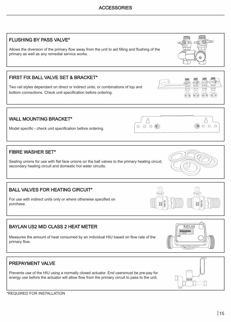
ACCESSORIESACCESSORIES
FLUSHING BY PASS VALVE*FLUSHING BY PASS VALVE*
Allows the diversion of the primary flow away from the unit to aid filling and flushing of the primary as well as any remedial service works.
WALL MOUNTING BRACKET*WALL MOUNTING BRACKET*
Model specific - check unit specification before ordering.
BAYLAN US2 MID CLASS 2 HEAT METERBAYLAN US2 MID CLASS 2 HEAT METER
Measures the amount of heat consumed by an individual HIU based on flow rate of the primary flow.
FIRST FIX BALL VALVE SET & BRACKET*FIRST FIX BALL VALVE SET & BRACKET*
Two rail styles dependant on direct or indirect units, or combinations of top and bottom connections. Check unit specification before ordering.
BALL VALVES FOR HEATING CIRCUIT*BALL VALVES FOR HEATING CIRCUIT*
For use with indirect units only or where otherwise specified on purchase.
FIBRE WASHER SET*FIBRE WASHER SET*
Sealing unions for use with flat face unions on the ball valves to the primary heating circuit,secondary heating circuit and domestic hot water circuits.
PREPAYMENT VALVEPREPAYMENT VALVE
Prevents use of the HIU using a normally closed actuator. End usersmust be pre-pay for energy use before the actuator will allow flow from the primary circuit to pass to the unit.
OFF ONONOFF
ON
ON
OFF
OFF ON OFFON OFF
DN20
PN25
CW61
7N
DN20
PN25
CW61
7N
������ULTRASONIC HEAT METER
8888888ckWhm3/h
*REQUIRED FOR INSTALLATION
16
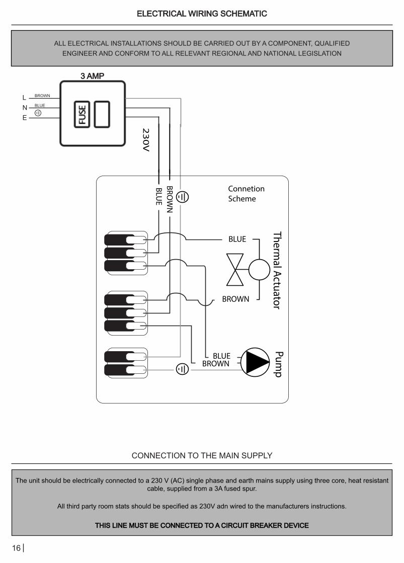
ELECTRICAL WIRING SCHEMATICELECTRICAL WIRING SCHEMATIC
ALL ELECTRICAL INSTALLATIONS SHOULD BE CARRIED OUT BY A COMPONENT, QUALIFIEDENGINEER AND CONFORM TO ALL RELEVANT REGIONAL AND NATIONAL LEGISLATION
CONNECTION TO THE MAIN SUPPLY
The unit should be electrically connected to a 230 V (AC) single phase and earth mains supply using three core, heat resistant cable, supplied from a 3A fused spur.
All third party room stats should be specified as 230V adn wired to the manufacturers instructions.
THIS LINE MUST BE CONNECTED TO A CIRCUIT BREAKER DEVICETHIS LINE MUST BE CONNECTED TO A CIRCUIT BREAKER DEVICE
3 AMP 3 AMP
LNE
BROWN
BLUE
Thermal Actuator
Pump
23
0V
Connetion Scheme
BLUEBLU
E
BLUE
BROWN
BROW
N
BROWN
17
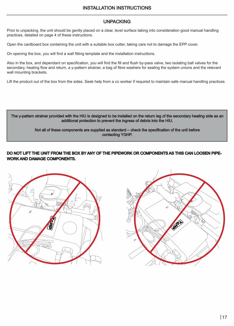
INSTALLATION INSTRUCTIONSINSTALLATION INSTRUCTIONS
UNPACKINGUNPACKING
Prior to unpacking, the unit should be gently placed on a clear, level surface taking into consideration good manual handling practices, detailed on page 4 of these instructions.
Open the cardboard box containing the unit with a suitable box cutter, taking care not to damage the EPP cover.
On opening the box, you will find a wall fitting template and the installation instructions.
Also in the box, and dependant on specification, you will find the fill and flush by-pass valve, two isolating ball valves for the secondary, heating flow and return, a y-pattern strainer, a bag of fibre washers for sealing the system unions and the relevant wall mounting brackets.
Lift the product out of the box from the sides. Seek help from a co worker if required to maintain safe manual handling practices
The y-pattern strainer provided with the HIU is designed to be installed on the return leg of the secondary heating side as an The y-pattern strainer provided with the HIU is designed to be installed on the return leg of the secondary heating side as an additional protection to prevent the ingress of debris into the HIU.additional protection to prevent the ingress of debris into the HIU.
Not all of these components are supplied as standard – check the specification of the unit before Not all of these components are supplied as standard – check the specification of the unit before contacting YGHP.contacting YGHP.
DO NOT LIFT THE UNIT FROM THE BOX BY ANY OF THE PIPEWORK OR COMPONENTS AS THIS CAN LOOSEN PIPE-DO NOT LIFT THE UNIT FROM THE BOX BY ANY OF THE PIPEWORK OR COMPONENTS AS THIS CAN LOOSEN PIPE-WORK AND DAMAGE COMPONENTS.WORK AND DAMAGE COMPONENTS.

18
FITTING LOCATIONFITTING LOCATION
WALL MOUNTINGWALL MOUNTING
The YGHP HIU should be installed on a flat, vertical wall that can support the weight of the unit, along with any other ancillary equipment.
The unit should be installed in a frost-free room where the temperature and humidity should not exceed 50°C and 60% respectively. Under no circumstances should these values, or any other values specified in these instructions, be exceeded.
The YGHP HIU is designed for installation in a domestic setting and should not be installed outside or in situations where it may be directly or indirectly exposed to atmospheric agents.
If the unit is to be sited between kitchen units or tight to walls, consideration should be given to access for future maintenance of the product. Product dimensions should be carefully checked prior to installation.
YGHP recommend that the unit is not installed above any other electrical installation within utility cupboards as they may be damaged in the event of a discharge of the safety relief valve, if it has not been connected to a suitable discharge and tundish, or the failure of a mechanical union within the unit.
In the event of a perceived product malfunction, or incorrect operation, a competent, authorised engineer should be contacted to electrically isolate the unit and conduct a fault-finding investigation, (see page 25).
In some installations where non-return valves have been fitted on the cold inlet to the DHW supply, a provision for expansion with the DHW circuit may need to be made. Failure to provide a means of expansion on the DHW circuit can lead to the over-pressure of the unit and the potential failure of mechanical unions.
IF YOU ARE EXPERIENCING AN ISSUE WITH THE PROVISION OF DHW OR HEATING, CHECK YOUR HEAT NETWORK IF YOU ARE EXPERIENCING AN ISSUE WITH THE PROVISION OF DHW OR HEATING, CHECK YOUR HEAT NETWORK IS OPERATING TO DESIGN SPECIFICATION.IS OPERATING TO DESIGN SPECIFICATION.
The unit is heavy. It is the installing engineer’s responsibility to select an appropriate fitting location and specify the correct wall fixings.
Once a suitable fitting location has been selected, present the wall mounting template to the wall. Use a spirit level to ensure the template is level.
Mark the wall where shown on the wall mounting template.
Drill holes of an appropriate size to your wall material and fixing method and then mount the first fix rail and hanging brackets to the wall.
It is recommended to use washers with whatever fixing you choose to improve contact with the bracket and spread the load.

19
HYDRAULIC CONNECTIONSHYDRAULIC CONNECTIONS
The YGHP HIU is pressure tested during it’s production. However, factory made mechanical unions may become loose during transit or because of the natural expansion and contraction of metals.
It is the installing engineer’s responsibility to ensure that all factory-made mechanical unions are checked for tightness prior to the filling and commissioning of the system.
The hydraulic connections made to the unit are flat face unions, sealed by a fibre washer.
There are two different sizes of fibre washer supplied with the unit. These are clearly designated for use between the heating and DHW side. Fitting the incorrectly specified washer may result in the failure of one or more mechanical joints.
It is the installing engineer’s responsibility to ensure that the safety relief valve supplied within the unit is safely connected to discharge according to the Water Regulations.
Failure to connect the safety relief valve to discharge may result in damage to both property and/or persons in the event the safety relief valve is activated.
ELECTRICAL CONNECTIONELECTRICAL CONNECTION
Connection of the unit to the electric supply should be made by an appropriately qualified, competent engineer and conform to any relevant regional and national legislative guidance.
The unit is designed to operate to the below specification:
• Electric supply line 230 V AC ± 10%
• Power frequency 50 -60 Hz
• Operating voltage 5 V AC ± 10%
• Input 0.15 - 3 W
• Protection IP44
ALL THIRD-PARTY ROOM STATS SHOULD BE SPECIFIED AS 230V MAINS POWEREDALL THIRD-PARTY ROOM STATS SHOULD BE SPECIFIED AS 230V MAINS POWERED
REFER TO THE ELECTRICAL SCHEMATIC ON PAGE 15 TO COMPLETE THE ELECTRICAL REFER TO THE ELECTRICAL SCHEMATIC ON PAGE 15 TO COMPLETE THE ELECTRICAL INSTALLATION OF THE UNIT.INSTALLATION OF THE UNIT.

20
COMMISSIONING THE SYSTEMCOMMISSIONING THE SYSTEM
FLUSHING THE HEAT NETWORKFLUSHING THE HEAT NETWORK
THE PRIMARY AND SECONDARY PIPEWORK MUST BE CLEAN AND FREE FROM DEBRIS BEFORE SYSTEM FLUID IS THE PRIMARY AND SECONDARY PIPEWORK MUST BE CLEAN AND FREE FROM DEBRIS BEFORE SYSTEM FLUID IS ALLOWED TO ENTER THE UNIT.ALLOWED TO ENTER THE UNIT.
FLUSHING AND CLEANSING SHOULD BE CARRIED OUT IN ACCORDANCE WITH THE GUIDANCE DETAILED IN BSRIA FLUSHING AND CLEANSING SHOULD BE CARRIED OUT IN ACCORDANCE WITH THE GUIDANCE DETAILED IN BSRIA GUIDANCE DOCUMENTS BG 50/2013 AND BG 29/2020.GUIDANCE DOCUMENTS BG 50/2013 AND BG 29/2020.
CONSIDERATION SHOULD ALSO BE GIVEN TO THE GUIDANCE WITHIN BS EN 12828:2012+A1:2014 ON WATER CONSIDERATION SHOULD ALSO BE GIVEN TO THE GUIDANCE WITHIN BS EN 12828:2012+A1:2014 ON WATER QUALITY RELATING TO VDI 2035.QUALITY RELATING TO VDI 2035.
DURING FLUSHING, ENSURE THAT THE UNIT REMAINS ISOLATED FROM THE SYSTEM AND THE FLUSHING BY-PASS DURING FLUSHING, ENSURE THAT THE UNIT REMAINS ISOLATED FROM THE SYSTEM AND THE FLUSHING BY-PASS VALVE REMAINS OPEN.VALVE REMAINS OPEN.
DO NOT FLUSH THROUGH THE UNIT.DO NOT FLUSH THROUGH THE UNIT.
CLEANSING THE SYSTEM USING THE FLUSHING BY-PASSCLEANSING THE SYSTEM USING THE FLUSHING BY-PASS
The ball valve assembly relevant to the flushing by-pass is shown below, (FIGURE.1).
Ball valves “E”, “F” and “H” are opened to start the system cleansing. All other ball valves remain closed, (FIGURE.2). While ball valves “E”, “F” and “H” are open, air can be purged from the system using the manual air vent operated by a flat head screwdriver.
When system cleansing has finished, ball valve “H” should be closed, (FIGURE.3).
abcd
efgh
2
OFF
ON
5
OFF
OFF
ON
FIGURE.1FIGURE.1 FIGURE.2FIGURE.2 FIGURE.3FIGURE.3
21
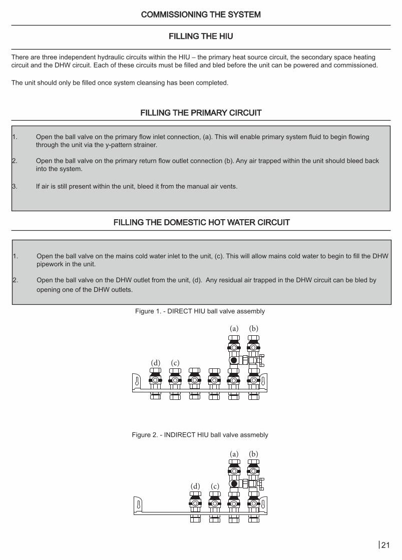
FILLING THE HIUFILLING THE HIU
COMMISSIONING THE SYSTEMCOMMISSIONING THE SYSTEM
There are three independent hydraulic circuits within the HIU – the primary heat source circuit, the secondary space heating circuit and the DHW circuit. Each of these circuits must be filled and bled before the unit can be powered and commissioned.
The unit should only be filled once system cleansing has been completed.
FILLING THE PRIMARY CIRCUITFILLING THE PRIMARY CIRCUIT
FILLING THE DOMESTIC HOT WATER CIRCUITFILLING THE DOMESTIC HOT WATER CIRCUIT
1. Open the ball valve on the primary flow inlet connection, (a). This will enable primary system fluid to begin flowing through the unit via the y-pattern strainer.
2. Open the ball valve on the primary return flow outlet connection (b). Any air trapped within the unit should bleed back into the system.
3. If air is still present within the unit, bleed it from the manual air vents.
1. Open the ball valve on the mains cold water inlet to the unit, (c). This will allow mains cold water to begin to fill the DHW pipework in the unit.
2. Open the ball valve on the DHW outlet from the unit, (d). Any residual air trapped in the DHW circuit can be bled by opening one of the DHW outlets.
Figure 1. - DIRECT HIU ball valve assembly
Figure 2. - INDIRECT HIU ball valve assmebly
(a)
(b)
(b)
(a)
(d)
(d)
(c)
(c)

22
FILLING THE SPACE HEATING CIRCUITFILLING THE SPACE HEATING CIRCUIT
COMMISSIONING THE SYSTEMCOMMISSIONING THE SYSTEM
DIRECT UNITSDIRECT UNITS
INDIRECT UNITSINDIRECT UNITS
THE SECONDARY SPACE HEATING CIRCUIT SHOULD BE CLEANSED AND FLUSHED IN ACCORDTHE SECONDARY SPACE HEATING CIRCUIT SHOULD BE CLEANSED AND FLUSHED IN ACCORDANCE WITH BSRIA ANCE WITH BSRIA DOCUMENT BG 50/2013 AND BS 7593:2019 BEFORE CONNECTING THE SYSTEM TO THE HIU.DOCUMENT BG 50/2013 AND BS 7593:2019 BEFORE CONNECTING THE SYSTEM TO THE HIU.
ENSURE THE Y-PATTERN STRAINER HAS BEEN INSTALLED ON THE RETURN LEG OF THE SECONDARY HEATING ENSURE THE Y-PATTERN STRAINER HAS BEEN INSTALLED ON THE RETURN LEG OF THE SECONDARY HEATING CIRCUITCIRCUIT
YGHP ALSO RECOMMEND THE INSTALLATION OF A MAGNETIC SYSTEM FILTER ON THE RETURN LEG OF THE YGHP ALSO RECOMMEND THE INSTALLATION OF A MAGNETIC SYSTEM FILTER ON THE RETURN LEG OF THE SECONDARY HEATING CIRUIT TO PREVENT DEBRIS INGRESS TO THE UNIT.SECONDARY HEATING CIRUIT TO PREVENT DEBRIS INGRESS TO THE UNIT.
THE HIU MUST REMAIN ISOLATED FROM BOTH THE PRIMARY AND SECONDARY SIDES OF THE SYSTEM WHILST THE HIU MUST REMAIN ISOLATED FROM BOTH THE PRIMARY AND SECONDARY SIDES OF THE SYSTEM WHILST CLEANSING AND FLUSHING TAKES PLACE.CLEANSING AND FLUSHING TAKES PLACE.
1. Open the ball valve on the space heating flow connection. This will allow water from the primary side to fill the space heating pipework through the y-pattern strainer.
2. Open the ball valve on the space heating return connection. Ensure the manifold within the unit has been bled and that all heat emitters on the secondary side are also free from air.
No provision is made within the indirect unit to fill the secondary heating circuit.
To fill the secondary heating circuit, a suitable WRAS approved filling loop, or other approved filling method, should be used.

23
PRE-COMMISSIONING CHECKLIST FOR YGHP HIUsPRE-COMMISSIONING CHECKLIST FOR YGHP HIUs
Confirmation of completion of the below checklist is required on each of the following points before YGHP’s customer service team will schedule a commissioning visit.
SITE DETAILS
Site Name
Site Address
Contractor
Site Contact
Phone
HIU Model Type
Number of Units
PRE-COMMISSIONING CHECKLISTNo. Activity YES/NO
1 Has the installation & commissioning of the primary heat source taken place?
2 What is the primary flow rate?
3 What is the primary flow temperature?
4 Do all dwellings have the primary heating loop circulating through the HIU?
5 Are all dwellings connected to the cold water supply?
6 Do all dwellings have the primary heating loop circulating through the HIU?
7 Are all heat emitters fitted and operational?
8 Do all swellings have fully operational hot and cold water outlets?
9 Are all third party heating controls connected and working?
10 Does the heat meter have a 1kWh consumption as a minimum?
11 Is every dwelling open and accessible?
Signed Print
Date
By completing and signing this document, you acknowledge the information provided is correct. If on arrival at the site, the information provided is found not be accurate, and commissioning of the units cannot take place, YGHP reserve the
right to exercise an ‘ABORTED VISIT CHARGE’ at our discretion.

24
HIU COMMISSIONING CHECKLISTHIU COMMISSIONING CHECKLIST
SITE DETAILS
Site Name
Site Address
Contractor
Site Contact
Phone
HIU Model Type
Number of Units
TEST INSPECTION UNIT RESULT COMMENTS
HIU space heating circuit pressure BarFlushing by-pass closed and sealed Y/NY-pattern strainer checked & cleaned Y/NPotable cold-water supply pressure BarThermostatic heads set correctly Y/NPump speed set correctly Y/NDHW temperature OCDHW flow rate l/minDHW response time sec.Pre-payment valve operating Y/NSpace heating actuator head operational Y/N
Third party room stat installed Y/NPrimary flow temp OCPrimary return temp OCPrimary flow rate l/hSecondary heating flow temp OCSecondary heating return temp OCDPCV commissioned correctly Y/NHeat meter energy consumption kWhHIU fully commissioned Y/NWRAS approved filling loop fitted Y/N
COMMISSIONING ENGINEER’S DETAILS
NameCompany Name
Signature
Date

FAULT FINDINGFAULT FINDING
Fault Possible Cause of Fault Solution
The water isnot heating
presence of air in the system remove the air using the vents provided
presence of debris in the system clean line strainers & check flow paths are clean
centralised system not working contact person in charge of the systemelectrical supply switched “off” turn the electrical supply “on”
protection fuse burnt out contact a qualified person to replaceprimary circuit isolating valve closed open the isolating valve
flushing by pass valve left open close the flushing by pass ball valve
The water is hot but does not
reach the desiredtemperature
set point of thermostat is wrong contact a qualified person to commission line strainer clogged remove and clean line strainers
plate heat exchanger partly clogged remove and flush plate heat exchangercentralised system temperature insuffi-
cientcontact the person in charge of the
system
primary flow rate insufficient contact the person in charge of the system
excessive demand for DHW reduce DHW demandThe hot water temperature
reached is toohigh
DHW control thermostat has not been commissioned contact a qualified person to commission
Hot water flowrate is insufficient
line strainer clogged remove and clean line strainersplate heat exchanger partly clogged remove and flush plate heat exchangerDHW isolating valves partially closed open the isolating valvecentralised cold water circuit fow rate
insufficientcontact the person in charge of the
system
There is no hot water flow
cold water inlet isolating “off” open the isolating valveDHW outlet isolating valve “off” open the isolating valve
line strainer clogged remove and clean line strainersplate heat exchanger partly clogged remove and flush plate heat exchanger
no cold water in centralised system contact the person in charge of the system
The room is not reaching the
desiredtemperature
heating set point is too low contact a qualified person to commissionline strainer clogged remove and clean line strainers
plate heat exchanger partly clogged remove and flush plate heat exchangerpresence of air in the system remove the air using vents provided
pump failure contact a qualified person to replacepump cable not connected restore connection
actuator head failure contact a qualified person to replaceactuator head not connected restore connection
isolating ball valves are closed open the isolating valvecentralised system temperature insuffi-
cientcontact the person in charge of the
system
primary circuit flow rate insufficient contact the person in charge of the system
centralised system not working contact the person in charge of the system
room thermostat not working contact a qualified person to investigateelectric supply switched “off” turn the electrical supply “on”
protection fuse burnt out contact a qualified person to replace
26
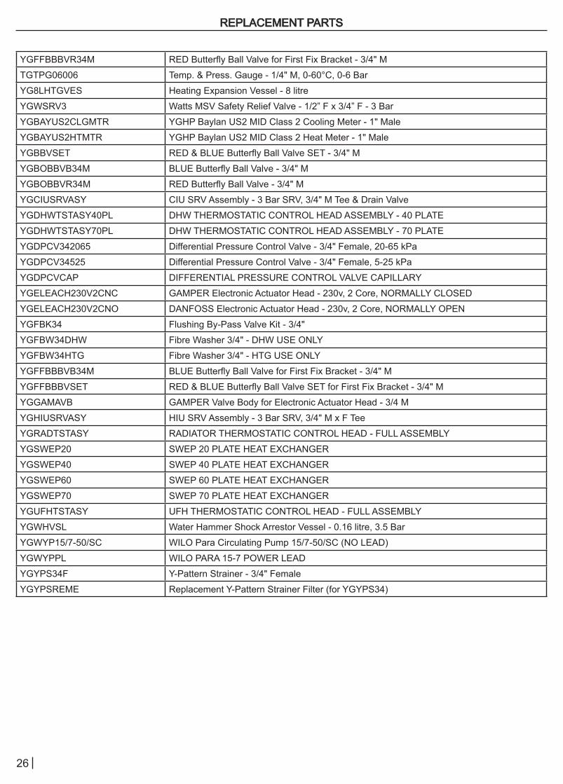
REPLACEMENT PARTSREPLACEMENT PARTS
YGFFBBBVR34M RED Butterfly Ball Valve for First Fix Bracket - 3/4" MTGTPG06006 Temp. & Press. Gauge - 1/4" M, 0-60°C, 0-6 BarYG8LHTGVES Heating Expansion Vessel - 8 litreYGWSRV3 Watts MSV Safety Relief Valve - 1/2” F x 3/4” F - 3 BarYGBAYUS2CLGMTR YGHP Baylan US2 MID Class 2 Cooling Meter - 1" MaleYGBAYUS2HTMTR YGHP Baylan US2 MID Class 2 Heat Meter - 1" MaleYGBBVSET RED & BLUE Butterfly Ball Valve SET - 3/4" MYGBOBBVB34M BLUE Butterfly Ball Valve - 3/4" MYGBOBBVR34M RED Butterfly Ball Valve - 3/4" MYGCIUSRVASY CIU SRV Assembly - 3 Bar SRV, 3/4" M Tee & Drain ValveYGDHWTSTASY40PL DHW THERMOSTATIC CONTROL HEAD ASSEMBLY - 40 PLATEYGDHWTSTASY70PL DHW THERMOSTATIC CONTROL HEAD ASSEMBLY - 70 PLATEYGDPCV342065 Differential Pressure Control Valve - 3/4" Female, 20-65 kPaYGDPCV34525 Differential Pressure Control Valve - 3/4" Female, 5-25 kPaYGDPCVCAP DIFFERENTIAL PRESSURE CONTROL VALVE CAPILLARYYGELEACH230V2CNC GAMPER Electronic Actuator Head - 230v, 2 Core, NORMALLY CLOSEDYGELEACH230V2CNO DANFOSS Electronic Actuator Head - 230v, 2 Core, NORMALLY OPENYGFBK34 Flushing By-Pass Valve Kit - 3/4"YGFBW34DHW Fibre Washer 3/4" - DHW USE ONLYYGFBW34HTG Fibre Washer 3/4" - HTG USE ONLYYGFFBBBVB34M BLUE Butterfly Ball Valve for First Fix Bracket - 3/4" MYGFFBBBVSET RED & BLUE Butterfly Ball Valve SET for First Fix Bracket - 3/4" MYGGAMAVB GAMPER Valve Body for Electronic Actuator Head - 3/4 MYGHIUSRVASY HIU SRV Assembly - 3 Bar SRV, 3/4" M x F TeeYGRADTSTASY RADIATOR THERMOSTATIC CONTROL HEAD - FULL ASSEMBLYYGSWEP20 SWEP 20 PLATE HEAT EXCHANGERYGSWEP40 SWEP 40 PLATE HEAT EXCHANGERYGSWEP60 SWEP 60 PLATE HEAT EXCHANGERYGSWEP70 SWEP 70 PLATE HEAT EXCHANGERYGUFHTSTASY UFH THERMOSTATIC CONTROL HEAD - FULL ASSEMBLYYGWHVSL Water Hammer Shock Arrestor Vessel - 0.16 litre, 3.5 BarYGWYP15/7-50/SC WILO Para Circulating Pump 15/7-50/SC (NO LEAD)YGWYPPL WILO PARA 15-7 POWER LEADYGYPS34F Y-Pattern Strainer - 3/4" FemaleYGYPSREME Replacement Y-Pattern Strainer Filter (for YGYPS34)

27
YGHP recommend that maintenance is checked every 12 months by an authorised, qualified engineer.
Before any maintenance is undertaken, the following checks should be made:
I. Isolate the product from the mains electricity supplyII. Make an additional electrical safety test to ensure the product is isolated from the mainsIII. Turn the water supply to the product off by using the isolating ball valvesIV. Remove the external EPP cover from the product V. Ensure the product is cool to the touch to reduce the risk of skin burns
Recommended maintenance checks are as follows:
I. Conduct a visual inspection of the unit to check for any leaks on pipe work unionsII. Check the operation of all isolating ball valvesIII. Inspect and clean any internal or external system filters, (y-pattern strainers etc)IV. Check the supply differential above required minimum.V. Inspect the EPP insulating cover is free from damageVI. Check the control valve functions are operable to DHW & heating demandVII. Check the primary supply temperatures to both the DHW and heating are to specification*VIII. Check mains pressure storage water heater safety valve** IX. Check the heat/cooling/water meter registers a demand or replace if scheduled**X. Check function of the pre-payment valve
*refer to the YGHP Commissioning Checklist for values**only applicable if fitted
MAINTENANCEMAINTENANCE

28
SERVICE RECORDSERVICE RECORD
Before completing the below service record, please make sure service is to standard described by YGHP Before completing the below service record, please make sure service is to standard described by YGHP instructionsinstructions
SERVICE: Date:_______________________Engineer Name: Company Name: Telephone Number: _____________________________________________ Signature_____________________________________
SERVICE: Date:_______________________Engineer Name: Company Name: Telephone Number: _____________________________________________ Signature_____________________________________
SERVICE: Date:_______________________Engineer Name: Company Name: Telephone Number: _____________________________________________ Signature_____________________________________
SERVICE: Date:_______________________Engineer Name: Company Name: Telephone Number: _____________________________________________ Signature_____________________________________
SERVICE: Date:_______________________Engineer Name: Company Name: Telephone Number: _____________________________________________ Signature_____________________________________
SERVICE: Date:_______________________Engineer Name: Company Name: Telephone Number: _____________________________________________ Signature_____________________________________
SERVICE: Date:_______________________Engineer Name: Company Name: Telephone Number: _____________________________________________ Signature_____________________________________
SERVICE: Date:_______________________Engineer Name: Company Name: Telephone Number: _____________________________________________ Signature_____________________________________
SERVICE: Date:_______________________Engineer Name: Company Name: Telephone Number: _____________________________________________ Signature_____________________________________
SERVICE: Date:_______________________Engineer Name: Company Name: Telephone Number: _____________________________________________ Signature_____________________________________

29
WARRANTYWARRANTYThe warranty for the YGHP range of Heat Interface Units (HIU) begins from the date of installation. The date of installation will be assumed to be the date of delivery unless YGHP Ltd are advised to the contrary and a future installation date is confirmed.
Individual products can be registered for warranty on the YGHP Ltd website at the below link;www.yghp.co.uk/warranty-registrationwww.yghp.co.uk/warranty-registration
Product registration is a condition of the warranty. Any product that has not been registered for warranty will be deemed not to be covered by the warranty, detailed below.
The warranty applies only where a YGHP HIU has been installed in a domestic dwelling in the United Kingdom, Northern Ireland or Republic of Ireland, to provide heat and/or hot water to an individual domestic dwelling.
The warranty is offered in addition to the rights provided to a consumer by law. Details of these rights can be obtained from the Trading Standards Authority or the Citizen Advice Bureaux.
YGHP Ltd offer a three year parts, inclusive of two years labour, warranty as standard.If the HIU is commissioned by a YGHP engineer, the warranty period is extended to seven years parts, inclusive of two years labour.
YGHP Ltd reserve the right to request a water quality sample be undertaken by a third party to validate any product warranty claims relating to component parts of the unit.
THE YGHP WARRANTY IS FREELY OFFERED WITH THE BELOW EXCEPTIONS:THE YGHP WARRANTY IS FREELY OFFERED WITH THE BELOW EXCEPTIONS:
• Any missing parts not reported within 14 days from receipt of delivery• Faults impeding the operation of the unit caused by central plant. This may include, but is not exclusive to, the following:
• Primary circuit flow rate and temperature• Cold water mains flow rate and pressure• Dirt and debris present in either the primary or secondary systems• Crossed pipework due to careless and/or poor installation practice• Any primary or secondary system condition in contravention to the specification
• Faults caused by the unit being installed by anyone deemed as ‘non-competent’• Faults arising from deviation from the manufacturer’s installation instructions• Faults arising from any changes or additions made to the unit without the manufacturer’s specific, written consent.• Faults arising from the use of non-original spare parts• Faults caused by the negligence of maintenance of the unit, as recommended in the manufacturer’s installation instructions.• Faults arising from the installation of units outside the UK that have not had the prior written consent of YGHP Ltd.• Any fault caused by water quality.• Faults relating to third party controls not supplied by YGHP Ltd.

30
THE WARRANTY DOES NOT INCLUDE:THE WARRANTY DOES NOT INCLUDE:
• Any unit installed under the below conditions:
• In contravention to the installation and maintenance guidance in the IOMs• Any units not installed in a domestic dwelling • Any units not installed in the United Kingdom or Republic of Ireland
• Any third-party costs that are unrelated to the repair, or replacement, of any component deemed to be at fault as a result of it’s manufacture.
• Any costs relating to descaling, cleaning, or power-flushing, the wider system, unit or individual component parts as a result of poor water quality.
• Any reduction or failure of performance of the unit as a result of poor water quality.• Any installation, or use of, the unit in direct contravention of the advice given in the manufacturer’s installation and operating
manual.• Any costs relating to the failure of the unit, or a component part, as a result of the recommende servicing schedule no being followed
If YGHP fit replacement parts as part of the warranty, this action alone will not be taken to extend the period of warranty from that originally stated.
All replaced parts, or complete units, will become and remain the property of YGHP Ltd.
The above information represents general guidance regarding the implementation of the Warranty. YGHP Ltd reserve the right to change and/or amend the conditions of this Warranty without prior notice. All
warranty claims may be subject to a third party water quality test at the discretion of YGHP Ltd.
YGHP RESERVE THE RIGHT TO CHARGE A CALLOUT FEE IN THE BELOW INSTANCES:YGHP RESERVE THE RIGHT TO CHARGE A CALLOUT FEE IN THE BELOW INSTANCES:
• There is no completed “commissioning sheet” or equivalent control document present• The service record is either incomplete or missing• No fault cannot be found• The breakdown or fault has been caused by an event which is excluded from the warranty.• Failure to cancel an agreed appointment prior to our engineers visit• The HIU is outside the period of warranty• The conditions of the warranty have not been met• If we fit replacement parts or replace a unit it will not extend the period of the warranty.• All replacement parts or units will become the property of YGHP Ltd.

Unit 9, Hemlock Park, Hyssop Close, Cannock, WS11 7FBWWW.YGHP.CO.UK | 01543 396 300 | [email protected]
09/20


