For contractor Please read carefully before installing and servicing. CAUTION! Observe the safety instructions of this installation and maintenance manual before placing the boiler in operation. DANGER! If installation, adjustment, modification, operation or maintenance of the heating system is carried out by an unqualified person, this may result in danger to life and limb or property damage. The directions of this installation and maintenance manual must be followed precisely. If you require assistance or further information, contact a qualified installer or an appropriate serv- ice provider. CAUTION! The installation and service instructions are a com- ponent of the technical documentation and must be handed over to the operator of the heating sys- tem. Discuss the instruction in this manual with the owner or operator of the heating system to ensure that they are familiar with all information required for operation of the heating system. Installation and maintenance instructions Solid fuel boiler Logano G201 6 720 618 151 - 08/2008 US
Transcript
For contractor
Please read carefully before installing and servicing.
CAUTION!Observe the safety instructions of this installation and maintenance manual before placing the boiler in operation.
DANGER!If installation, adjustment, modification, operation or maintenance of the heating system is carried out by an unqualified person, this may result in danger to life and limb or property damage. The directions of this installation and maintenance manual must be followed precisely.If you require assistance or further information, contact a qualified installer or an appropriate serv-ice provider.
CAUTION!The installation and service instructions are a com-ponent of the technical documentation and must be handed over to the operator of the heating sys-tem. Discuss the instruction in this manual with the owner or operator of the heating system to ensure that they are familiar with all information required for operation of the heating system.
Installation and maintenance instructions
Solid fuel boiler
Logano G201
6 72
0 61
8 15
1 - 0
8/20
08 U
S
Contents
Logano G201 - Subject to technical modifications.2
9 Shutting down the boiler . . . . . . . . . . . . . . . . . 379.1 Shutting down the boiler temporarily . . . 379.2 Shutting down the boiler for a long
period . . . . . . . . . . . . . . . . . . . . . . . . . . . .379.3 Shutting down the boiler in an
Logano G201 - Subject to technical modifications. 3
1 Safety instructions and symbol key
1.1 Explanation of symbols
Signal words are used to indicate the level of risk if coun-termeasures are not taken.
– Caution indicates that minor damage to property may occur.
– Warning indicates that minor personal injury or severe damage to property may occur.
– Danger means that severe personal injury may occur. Very serious cases may result in death.
Notes contain important information in cases where there is no risk to the user or the appliance.
1.2 General safety instructions
Risk of poisoning. Dangerous flue gas can escape if the air supply is insufficientV Never close off or reduce the size of air inlet or outlet
vents.V The boiler must not be operated until the obstruction
has been removed.V Inform the system operator in writing of the problem
and associated danger.
Explosive or easily flammable materialsV Do not store flammable materials or liquids near the
boiler.V Maintain minimum distances to combustible materials.
Installation, operationV Only have the appliance installed by an approved heat-
ing contractor.V Do not modify any parts that carry flue gas.V Do not operate the appliance without a sufficient quan-
tity of water.V Only use approved fuels according to the rating plate.V Do not cover or reduce the size of ventilation openings
in doors, windows and walls.
Maintenance and servicingV Recommendation: sign a maintenance and inspection
contract with an approved heating contractor and have the appliance serviced annually.
V The operator is responsible for the general and environ-mental safety of the system.
V Read and follow the safety instructions in the "Cleaning and maintenance" chapter.
V Use only genuine spare parts.
Combustion/room airV Keep combustion/room air free of aggressive materials
(e.g. ones that contain halogenated hydrocarbons, chlorine or fluorine compounds). In that way you will prevent corrosion.
Instructing the customerV Instruct customers about the functions and operation
of the appliance.V Inform the customer that he/she must not carry out any
alterations or repairs.V Instruct customers that children may not go near the
heating system when unsupervised by an adult.
Safety instructions in the text are marked with a warning triangle and printed on a gray background.
Notes are identified in the text by this sym-bol. They are separated by horizontal lines above and below the text.
2 Information about the appliance
Logano G201 - Subject to technical modifications.4
2 Information about the applianceThis installation and maintenance manual contains impor-tant information for the safe and correct installation, initial commissioning, and maintenance of this boiler.
This manual is intended for qualified technicians with experience and training in heating systems.
For operating information about the boiler, see the operat-ing instructions.
2.1 Designated useThe Logano G201 solid fuel boiler is a heating boiler for coal and wood firing (split log firing) in single and multi-family houses. In order to ensure proper use, please observe the details on the rating plate and the specifica-tions to ensure proper use of this appliance.
2.2 Standards, regulations and direc-tives
Boiler usage conditionsThe heat exchanger has been designed and certified in accordance with the ASME Boiler and Vessel Code, Section IV.
Maximum boiler temperature: 200 °F
Maximum operating pressure: 50 psi
2.3 Installation tips
When installing the heating system, observe the following requirements:
– Local building regulations regarding the installation conditions
– Local building code regulations regarding combustion air supply and flue gas systems
– Regulations and standards regarding safety equipment of the heating system
2.4 Operating tipsWhen operating the heating system observe the follow-ing:
V The boiler may only be operated by adults who are familiar with the instructions and boiler operation.
V Make sure that children are not allowed in the vicinity of the boiler unsupervised when it is in operation.
V Do not use any fluids for lighting or boosting the boiler.V Empty the ashes into a non-flammable container with a
lid.V Do not place or store any flammable objects near the
filling or combustion chamber or at a safety distance of at least 24 inches around the boiler.
V Do not place any flammable objects on the boiler.V Only clean the surface of the boiler with non-flammable
cleaners.V Do not store any flammable materials in the boiler room
(e.g. petroleum, oil).V Do not use any flammable liquids for heating.V While the boiler is operating, do not exceed the rated
output of the boiler (overheating).V Store ashes in a fireproof container with a closed
cover.V Operate the boiler at a maximum temperature of 194 °F
and check it regularly during operation.V Operate the boiler with a minimum return temperature
of 131 °F. Ensure that this temperature limit is adhered to with a suitable set-up.
V The minimum boiler water temperature must be above 131 °F, because with a lower temperature, flue gases can condense. This has negative consequences for the proper operation of the boiler and its life span.
V The boiler operator must follow the operating instruc-tions.
V The boiler operator may only commission the boiler, take the boiler out of operation, and clean it. All other work must be performed by an authorized service com-pany.
V The service technician is obligated to inform the boiler operator about the operation and the correct, safe operation of the boiler.
V In case of danger of explosion, fire, escaping combus-tible gases or vapors (e.g. vapors that arise when glu-ing linoleum, PVC, etc.), do not operate the boiler.
V Heed the flammability of building materials.
Follow local regulations and standards dur-ing installation and operation!Installation of the heating system must be performed by an approved and qualified installer according to the valid standard NFPA-31 "Installation of solid fuel systems". The installation must correspond to the na-tional and local standards and rules. For the USA/Canada, the standards UL391/CSA/CAN B366.1 must be adhered to.
Only use original Buderus spare parts. Bud-erus assumes no liability for damage caused by the use of parts not supplied by Buderus.
2Information about the appliance
Logano G201 - Subject to technical modifications. 5
2.5 Air supply 2.6 Minimum clearances and flammabil-ity of building materials
V Different minimum clearances from those specified below may apply in certain countries. Ask your heating contractor or the flue installer about this.
V The minimum distance from combustible materials is 24 inches. A clearance of 24 inches should also be maintained if the flammability of the materials is not known.
2.7 Tools, Materials and AccessoriesFor the installation and maintenance of the boiler, you will need the standard tools used for central heating and oil/gas and water systems.
Danger: Risk of fatal injury from lack of oxygen in the boiler room!V Make sure there is adequate fresh-air ven-
tilation by providing air vents to the out-side.
V Point out to the system operator that those air vents must remain open.
Warning: System damage and risk of injury in case of incorrect commissioning! Lack of adequate air for combustion can lead to creosote formation.
V Make sure there is adequate fresh-air ven-tilation by providing air vents to the out-side.
V Point out to the system operator that those air vents must remain open.
Warning: Risk of system damage due to aggressive materials in the ventilation! During combustion, halogenated hydrocar-bons that contain chlorine or fluorine com-pounds cause increased corrosion in the boiler.
V Keep ventilation free of aggressive materi-als.
The boiler draws in the required combustion air from the environment. The boiler may only be set up and operated in rooms that are per-manently well-ventilated!
Logano G201 - Subject to technical modifications.6
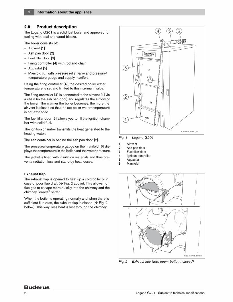
2.8 Product descriptionThe Logano G201 is a solid fuel boiler and approved for fueling with coal and wood blocks.
The boiler consists of:– Air vent [1]– Ash pan door [2]– Fuel filler door [3]– Firing controller [4] with rod and chain– Aquastat [5]– Manifold [6] with pressure relief valve and pressure/
temperature gauge and supply manifold.
Using the firing controller [4], the desired boiler water temperature is set and limited to this maximum value.
The firing controller [4] is connected to the air vent [1] via a chain (in the ash pan door) and regulates the airflow of the boiler. The warmer the boiler becomes, the more the air vent is closed so that the set boiler water temperature is not exceeded.
The fuel filler door [3] allows you to fill the ignition cham-ber with solid fuel.
The ignition chamber transmits the heat generated to the heating water.
The ash container is behind the ash pan door [2].
The pressure/temperature gauge on the manifold [6] dis-plays the temperature in the boiler and the water pressure.
The jacket is lined with insulation materials and thus pre-vents radiation loss and stand-by heat losses.
Fig. 1 Logano G201
1 Air vent2 Ash pan door3 Fuel filler door4 Ignition controller5 Aquastat6 Manifold
Exhaust flapThe exhaust flap is opened to heat up a cold boiler or in case of poor flue draft ( Fig. 2 above). This allows hot flue gas to escape more quickly into the chimney and the chimney "draws" better.
When the boiler is operating normally and when there is sufficient flue draft, the exhaust flap is closed ( Fig. 2 below). This way, less heat is lost through the chimney.
Fig. 2 Exhaust flap (top: open; bottom: closed)
2Information about the appliance
Logano G201 - Subject to technical modifications. 7
2.9 DisposalV Packing materials made of wood and paper can be
burned in the boiler.V Dispose of packaging in an environmentally responsi-
ble manner.V Dispose of old devices in an environmentally responsi-
ble manner at an authorized disposal site.
2.10 Scope of deliveryWhen receiving the boiler, observe the following:
V When receiving the delivery, check if the packaging is intact.
V Check that all package contents are present.V Dispose of packaging in an environmentally responsi-
ble manner.
Fig. 3 Scope of delivery
1 Box with boiler jacket2 Europallet3 Boiler heat exchanger4 Special pallet
ComponentNum-ber Packaging
Boiler heat exchanger 1 On pallet
Boiler jacket 1 In a box on a sep-arate pallet
Firing controller 1
Flue gas header 1 Factory-fitted
Installation material 1 Foil package in the combustion chamber
Technical documenta-tion
1 Foil package
Ash pan 1 In the boiler block
B-Kit 1 In the box
Tab. 2 Scope of delivery
2 Information about the appliance
Logano G201 - Subject to technical modifications.8
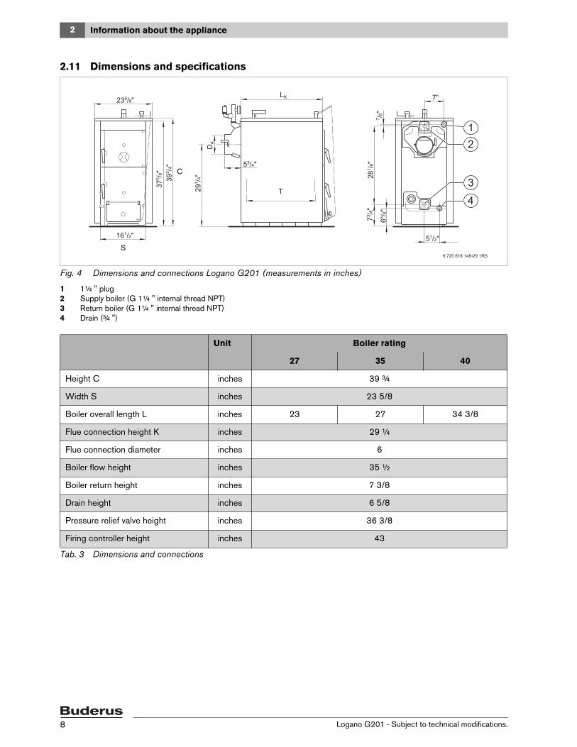
2.11 Dimensions and specifications
Fig. 4 Dimensions and connections Logano G201 (measurements in inches)
Tab. 4 Technical specifications1) fuel wood with high calorific value (beech, oak, maple) and maximum humidity of 20%
2 Information about the appliance
Logano G201 - Subject to technical modifications.10
2.11.2 Flow resistance graph
Fig. 5 Flow resistance depending on the volumetric flow rate
3General instructions about the fuels wood and coal
Logano G201 - Subject to technical modifications. 11
3 General instructions about the fuels wood and coalWood and coal can be used as fuels.
The flue gas temperatures are generally 212 – 392 °F. Depending on local conditions, fuels used (wood or coal), and how clean the boiler is, these values can be exceeded.
3.1 Wood firingPrescribed is split and dried wood with a diameter of 6 inches or less and a maximum wood humidity of 20 %.
Only use dry, natural, chunky wood. With a wood humidity of more than 20 %, the boiler output is reduced. In addi-tion, there can be increased tar formation, which reduces the life span of the boiler. The specified output values and the trouble-free function of the boiler can only be guaran-teed with a maximum wood humidity of up to 20 %.
As substitute fuels, the following are permissible (reduced output and shorter maintenance intervals): wood briquets, and wood chips.
3.2 Coal firingBest suited are anthracite coal and coke – any kind of lump 1 (0.8 – 1.6 inches). The burning times for coal are significantly longer than the burning times for wood.
As substitute fuels, the following are permissible (reduced output and shorter maintenance intervals): anthracite coal and coke type lump 2 (0.4 – 0.8 inches) or fragments (1.6 – 4.0 inches) and pressed fuels.
3.3 Condensate and tar formationImproper operation of the boiler causes excessive con-densate and tar formation. This way, damage to the boiler and the flue gas system can occur.
When heating up the cold boiler, water condenses in the boiler, which runs down on the interior walls. This way, you might think that the boiler is draining off. This "sweat-ing" of the boiler ends as soon as the ashes accumulate on the interior walls of the boiler.
In case of operation at low boiler return temperature (less than 131 °F) and fuel with too high a humidity content, condensation can also form on the heating surfaces. Here too, the condensation runs downwards.
Heating with too low a boiler temperature causes tar for-mation and can cause premature damage to the flue gas system due to sooting.
V Follow the operating instructions for the boiler.V Operate the boiler at the recommended operating tem-
peratures.V Only heat the boiler with the recommended fuels
( Chapter 3.1 and 3.2).V Remove tar accumulations with the cleaning scraper
when the boiler is warm.
Danger: Danger of fatal accident due to escaping carbon monoxide (CO)!In case of firing with brown coal, the boiler can silt up and CO can escape.
V Do not use brown coal for firing.
Danger: Health and/or system damage due to the use of unsuitable fuels! The use of unsuitable fuels can create mate-rials that endanger health and/or the heating system.
V Do not use plastics, household waste, chemically-treated wood, old paper, chips, bark or chipboard waste for firing.
Boiler typeMaximum length of split
or chipped wood
27 15 ¼ inches
35 19 ¼ inches
40 27 ¼ inches
Tab. 5 Maximum length of split or chipped wood
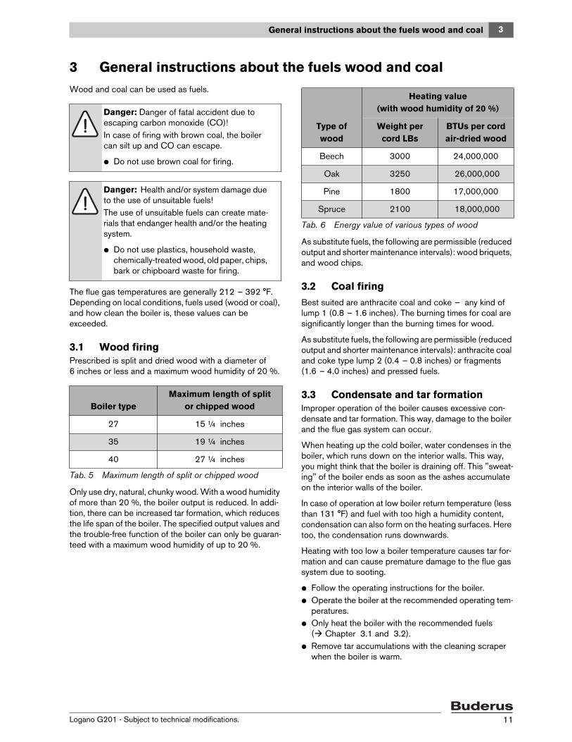
Type of wood
Heating value (with wood humidity of 20 %)
Weight per cord LBs
BTUs per cord air-dried wood
Beech 3000 24,000,000
Oak 3250 26,000,000
Pine 1800 17,000,000
Spruce 2100 18,000,000
Tab. 6 Energy value of various types of wood
4 Transport and set-up
Logano G201 - Subject to technical modifications.12
4 Transport and set-upThis chapter describes how to transport the boiler block safely and how to set it up in the boiler room.
Bring the boiler block into the boiler room with a dolly and transport belts.
Danger: Risk of fatal injury!Falling loads can cause fatal injuries.
V Please observe the safety instructions for transporting heavy loads with a dolly.
V Use personal protective equipment (e.g. helmet, safety shoes, protective gloves).
Caution: Risk of system damage from im-pact shocks!Fragile components could be damaged.
V Observe the transport instructions on the packaging.
Protect boiler connections from dirt if the boiler is not to be installed immediately.
Dispose of packaging in an environmentally responsible manner.
4Transport and set-up
Logano G201 - Subject to technical modifications. 13
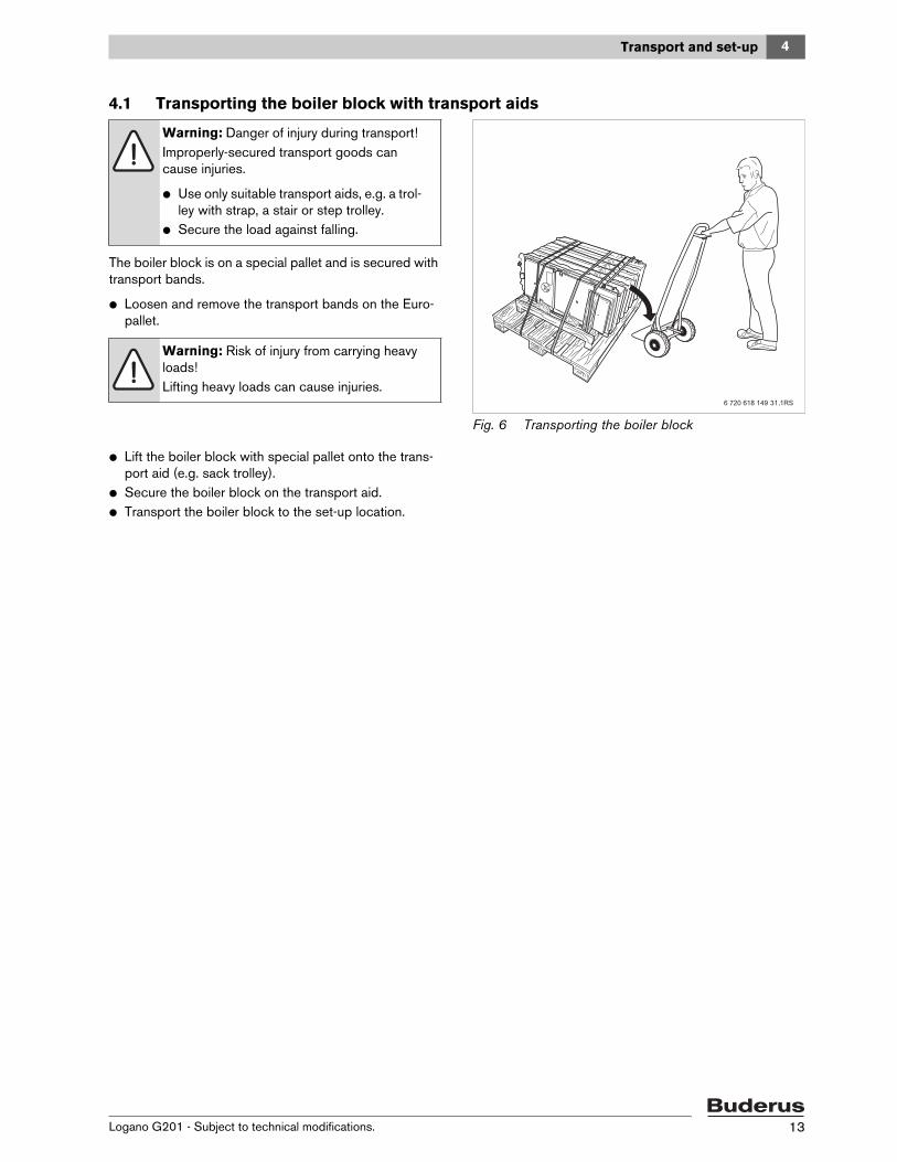
4.1 Transporting the boiler block with transport aids
The boiler block is on a special pallet and is secured with transport bands.
V Loosen and remove the transport bands on the Euro-pallet.
Fig. 6 Transporting the boiler block
V Lift the boiler block with special pallet onto the trans-port aid (e.g. sack trolley).
V Secure the boiler block on the transport aid.V Transport the boiler block to the set-up location.
Warning: Danger of injury during transport! Improperly-secured transport goods can cause injuries.
V Use only suitable transport aids, e.g. a trol-ley with strap, a stair or step trolley.
V Secure the load against falling.
Warning: Risk of injury from carrying heavy loads!Lifting heavy loads can cause injuries.
4 Transport and set-up
Logano G201 - Subject to technical modifications.14
4.2 Installing the boiler block
4.2.1 Installation requirements for the set-up room
4.2.2 Wall clearancesWherever possible, position the boiler with the recom-mended wall clearances. Reducing the wall clearances makes the boiler more difficult to access.
The non-combustible boiler base or foundation must be perfectly flat and level. If the foundation is not level, the connection side (rear) can be 0.2 inches higher for improved bleeding and air flow. The foundation must be larger than the boiler footprint – by at least 48 inches in the front and approx. 24 inches on the rear. The base must be able to bear the weight of the boiler. We recom-mend a stable concrete base.
Fig. 7 Wall clearances
Caution: Risk of system damage due to frost!If the heating system has been switched off, it may freeze up in cold weather conditions.
V Install the heating system in a frost-free room.
Danger: Risk of death from explosion and fire!The storage of explosive or easily-flammable materials near the boiler can create life-threatening situations.
V Do not store easily-combustible and ex-plosive materials (paper, curtains, cloth-ing, thinners, paints, etc.) near the boiler.
V Maintain a clearance of 24 inches from the boiler.
Dimension Wall clearancesA 48"B 24"C 6"
Top 24"Flue gas line from combus-tible materials
18"
Tab. 7 Wall clearances (dimensions in inches)
We recommend placing the boiler on a 2 – 4 inch high non-combustible base.
4Transport and set-up
Logano G201 - Subject to technical modifications. 15
Installing and aligning the boiler blockV Loosen and remove the transport bands on the special
pallet.
V Lift the boiler block from the special pallet.V Set the boiler block on the prepared base.V If necessary, align the boiler block with wedges [1] of
non-flammable material and with the help of a level in the horizontal and vertical directions.
Fig. 8 Installing and aligning the boiler block
1 Wedge (of non-flammable material)
Warning: Risk of injury from carrying heavy loads!Lifting heavy loads can cause injuries.
V Always lift the boiler block with at least two people.
5 Installation
Logano G201 - Subject to technical modifications.16
5 Installation
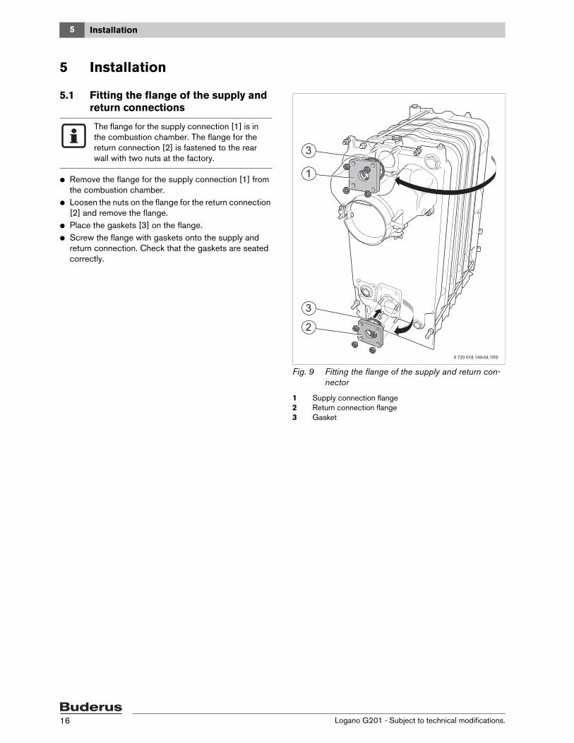
5.1 Fitting the flange of the supply and return connections
V Remove the flange for the supply connection [1] from the combustion chamber.
V Loosen the nuts on the flange for the return connection [2] and remove the flange.
V Place the gaskets [3] on the flange.V Screw the flange with gaskets onto the supply and
return connection. Check that the gaskets are seated correctly.
Fig. 9 Fitting the flange of the supply and return con-nector
The flange for the supply connection [1] is in the combustion chamber. The flange for the return connection [2] is fastened to the rear wall with two nuts at the factory.
5Installation
Logano G201 - Subject to technical modifications. 17
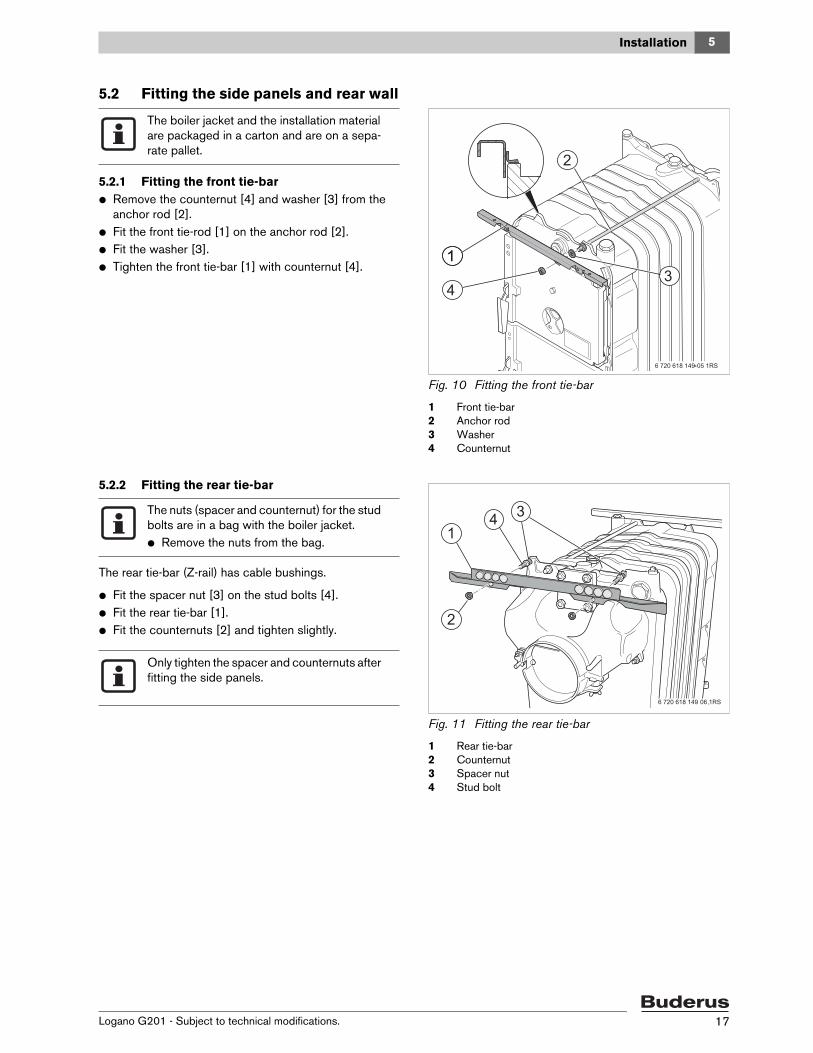
5.2 Fitting the side panels and rear wall
5.2.1 Fitting the front tie-barV Remove the counternut [4] and washer [3] from the
anchor rod [2].V Fit the front tie-rod [1] on the anchor rod [2].V Fit the washer [3].V Tighten the front tie-bar [1] with counternut [4].
Fig. 10 Fitting the front tie-bar
1 Front tie-bar2 Anchor rod3 Washer4 Counternut
5.2.2 Fitting the rear tie-bar
The rear tie-bar (Z-rail) has cable bushings.
V Fit the spacer nut [3] on the stud bolts [4].V Fit the rear tie-bar [1].V Fit the counternuts [2] and tighten slightly.
Fig. 11 Fitting the rear tie-bar
1 Rear tie-bar2 Counternut3 Spacer nut4 Stud bolt
The boiler jacket and the installation material are packaged in a carton and are on a sepa-rate pallet.
The nuts (spacer and counternut) for the stud bolts are in a bag with the boiler jacket.V Remove the nuts from the bag.
Only tighten the spacer and counternuts after fitting the side panels.
5 Installation
Logano G201 - Subject to technical modifications.18
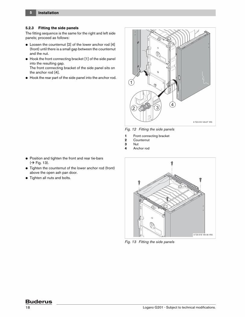
5.2.3 Fitting the side panelsThe fitting sequence is the same for the right and left side panels; proceed as follows:
V Loosen the counternut [2] of the lower anchor rod [4] (front) until there is a small gap between the counternut and the nut.
V Hook the front connecting bracket [1] of the side panel into the resulting gap.The front connecting bracket of the side panel sits on the anchor rod [4].
V Hook the rear part of the side panel into the anchor rod.
Fig. 12 Fitting the side panels
1 Front connecting bracket2 Counternut3 Nut4 Anchor rod
V Position and tighten the front and rear tie-bars ( Fig. 13).
V Tighten the counternut of the lower anchor rod (front) above the open ash pan door.
V Tighten all nuts and bolts.
Fig. 13 Fitting the side panels
5Installation
Logano G201 - Subject to technical modifications. 19
5.2.4 Fitting the rear panelV Hook the rear panel [1] below into the tabs [2] of the
side panels.V Fasten the rear panel [1] above with two bolts to the
side panels.
Fig. 14 Fitting the rear panel
1 Rear panel2 Tabs
5.3 Sealing the firing controllerV Remove the plugs [1] for the connection of the firing
controller. The connection is in the front part in the upper right.
V Seal the firing controller [3].
Fig. 15 Sealing the firing controller
1 Plug2 Red marking3 Firing controller
After sealing, the red marking [2] on the firing controller points directly forward.
5 Installation
Logano G201 - Subject to technical modifications.20
5.4 Sealing the immersion sleeve (Aquastat scope of delivery)
V Remove the plugs [2] for the connection of the Aqu-astat. The connection is on the top in the middle of the rear section [3].
V Seal the immersion sleeve [1] (Aquastat scope of deliv-ery) in the rear section [3].
Fig. 16 Sealing the immersion sleeve
1 Immersion sleeve2 Plug3 Rear section
5.5 Installing the front and rear boiler cover
V Cut out the pre-punched openings [1, 2] for the ignition controller and the Aquastat in the front and rear boiler cover [5, 4] with tin shears.
V Place the thermal insulation [6] on the boiler block so that the cross-shaped cut-out [3] lies above the con-nection for the Aquastat.
Fig. 17 Installing the front and rear boiler cover
1 Pre-punched opening in the rear boiler cover2 Pre-punched opening in the front boiler cover3 Cross-shaped cut-out4 Rear boiler cover5 Front boiler cover6 Thermal insulation
5Installation
Logano G201 - Subject to technical modifications. 21
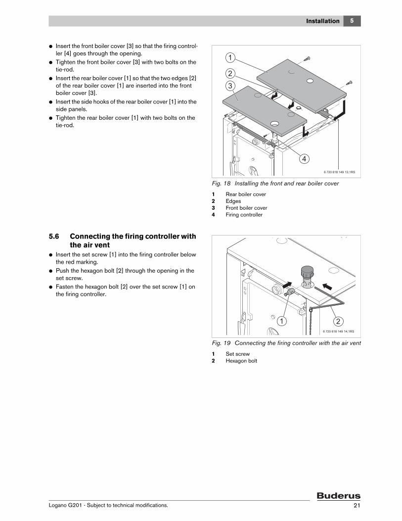
V Insert the front boiler cover [3] so that the firing control-ler [4] goes through the opening.
V Tighten the front boiler cover [3] with two bolts on the tie-rod.
V Insert the rear boiler cover [1] so that the two edges [2] of the rear boiler cover [1] are inserted into the front boiler cover [3].
V Insert the side hooks of the rear boiler cover [1] into the side panels.
V Tighten the rear boiler cover [1] with two bolts on the tie-rod.
Fig. 18 Installing the front and rear boiler cover
1 Rear boiler cover2 Edges3 Front boiler cover4 Firing controller
5.6 Connecting the firing controller with the air vent
V Insert the set screw [1] into the firing controller below the red marking.
V Push the hexagon bolt [2] through the opening in the set screw.
V Fasten the hexagon bolt [2] over the set screw [1] on the firing controller.
Fig. 19 Connecting the firing controller with the air vent
1 Set screw2 Hexagon bolt
5 Installation
Logano G201 - Subject to technical modifications.22
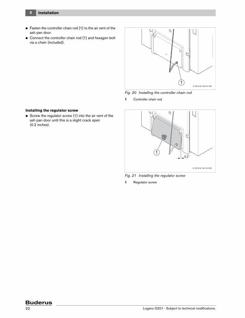
V Fasten the controller chain rod [1] to the air vent of the ash pan door.
V Connect the controller chain rod [1] and hexagon bolt via a chain (included).
Fig. 20 Installing the controller chain rod
1 Controller chain rod
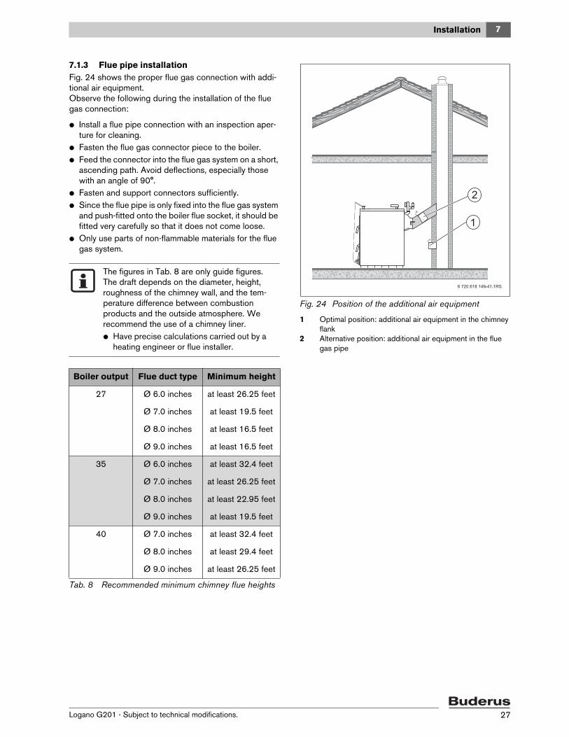
Installing the regulator screwV Screw the regulator screw [1] into the air vent of the
ash pan door until this is a slight crack open (0.2 inches).
Fig. 21 Installing the regulator screw
1 Regulator screw
5Installation
Logano G201 - Subject to technical modifications. 23
5.7 Installing the front faceplateV Install the protective bar [3] in the front faceplate [1].V Insert the faceplate [1] with protective bar [3] and fas-
ten with two bolts to the side panels.V Affix the appliance insignia plate [2] to the faceplate
[1].
Fig. 22 Installing the front faceplate
1 Front faceplate2 Appliance insignia plate3 Protective bar
5.8 Installing the AquastatV Drill four holes in the rear boiler cover [4] for fastening
the Aquastat [1] ( Fig. 23).V Insert temperature sensor [2] of the Aquastat into the
immersion sleeve [3] on the rear section.V Fasten the Aquastat [1] on the rear boiler cover [4].
Fig. 23 Installing the Aquastat
1 Aquastat2 Temperature sensor3 Immersion sleeve4 Rear boiler cover
6 720 618 151-18.2TL
6 Openings for combustion air supply and venting
Logano G201 - Subject to technical modifications.24
6 Openings for combustion air supply and ventingTo ensure an adequate combustion air supply and venting of the heating system suitable measures must be taken in accordance with the NFPA 31 Air for Combustion and Ventilation, or the local codes. In Canada, the regulations in accordance with CSA/CGA–B 149.1 and 2 Installation Codes apply.
Overall air supply within the buildingMake sure that the boiler room has two permanent air vents that are connected to one or more other rooms. When calculating the cross-sectional areas of the vent apertures, the total burner output of all gas-fired appli-ances in the connected rooms must be taken into account. Each vent must have a minimum cross-section of one square inch per 1000 Btu/h of the total burner output of all gas-fired appliances inside the connected rooms. Make sure that the cross-sectional area of each vent is at least 100 square inches. One of the vents must be no more than 12" from the ceiling and the other no more than 12" from the floor of the boiler room, measured from the outer edge of the vent aperture. The smallest dimension of all inlet and outlet vents must be not less than 3".
Total air supply from outside the buildingMake sure that the boiler room has two permanent air vents, one of which must not be more than 12" from the ceiling and the other not more than 12" from the floor of the boiler room, measured from the outer edge of the vent aperture. The vents must be connected either directly or via air ducts to the outside or to rooms that have an unob-structed connection to the open air (crawl passage or roof space). The smallest dimension of all inlet and outlet vents must be not less than 3".
Caution: Risk of boiler damage and mal-functions due to missing or inadequate open-ings for combustion air and venting of the boiler room.The openings for combustion air supply and venting are always required regardless of whether the combustion air is supplied from the room (operation from room air) or directly to the boiler through ducts (operation inde-pendent of room air).Inadequate venting of the boiler room may result in excessive ambient tem-peratures. This can damage the boiler.Inadequate combustion air supply may cause malfunctions in operation.
V Make sure that air inlet or outlet vents are not closed off or their size reduced and that they are adequately dimensioned.
V The boiler must not be operated until the obstruction has been removed.
V Draw the operator's attention to any defi-ciencies and the potential dangers.
Caution: Risk of boiler damage from con-taminated combustion air.V Never use cleaning agents that contain
chlorine or halogenated hydrocarbons (e.g. in spray cans, solvents and cleaning agents, paints, glues).
V Do not store or use such substances in the boiler room.
V Avoid excessive dust accumulation.
If contamination of the combustion air is pos-sible (e.g. installation near swimming pools, dry cleaners or hair salons), operation with air outside the room is recommended.
Danger: Dangers posed by explosive and easily combustible materials.V Do not use or store combustible materials
(paper, curtains, clothing, thinners, paints, etc.) in the boiler room.
V Maintain a clearance of 24 inches from the boiler.
6Openings for combustion air supply and venting
Logano G201 - Subject to technical modifications. 25
– If there is a direct connection to the outside, each opening must have a minimum cross-section of one square inch per 4000 Btu/h of the total combustion output of all combustion-fired appliances inside the closed room.
– If there is a direct connection to the outside via a venti-lated attic with vertical ventilation ducts, each opening must have a minimum cross-section of one square inch per 4000 Btu/h of the total combustion output of all combustion-fired appliances inside the closed room. The attic must be ventilated on both sides of the house.
– If there is a connection to the outside through horizon-tal ventilation ducts, each vent aperture must have a minimum cross-section of one square inch per 2000 Btu/h of the total burner output of all combustion-fired appliances inside the closed room. The ventilation ducts must have the same cross-section as the intake opening.
– If there is a direct connection to the outside via a venti-lated attic with vertical ventilation ducts, each opening must have a minimum cross-section of one square inch per 4000 Btu/h of the total combustion output of all combustion-fired appliances inside the closed room. The attic must be ventilated on both sides of the house.
7 Installation
Logano G201 - Subject to technical modifications.26
7 Installation
7.1 Air intake and flue gas connection
7.1.1 Notes about air intake connection
7.1.2 Notes about flue gas connection
A sufficient flue draft of the flue gas system is the basic requirement for the correct functioning of the boiler. It fun-damentally affects its performance and efficiency. There-fore, heed the following for the flue gas connection:
– Please note that the boiler must be connected to the flue gas system in accordance with the relevant local building code regulations and in consultation with an approved flue installer.
– The boiler may only be connected to a flue gas system with proper flue draft ( Tab. 4, page 9).
– The dimensioning calculations of the flue gas path must be based on the flue gas mass-flow rate at maxi-mum rated output. The effective chimney flue height is measured from the point of entry of the flue pipe into the chimney.
Danger: Risk of fatal injury from lack of oxy-gen in the boiler room!V Make sure there is adequate fresh-air ven-
tilation by providing air vents to the out-side.
V Point out to the system operator that those air vents must remain open.
Danger: System damage and risk of injury in case of incorrect commissioning!Lack of adequate air for combustion can lead to creosote formation.
V Make sure there is adequate fresh-air ven-tilation by providing air vents to the out-side.
V Point out to the system operator that those air vents must remain open.
Warning: Risk of system damage due to ag-gressive materials in the ventilation! During combustion, halogenated hydrocar-bons that contain chlorine or fluorine com-pounds cause increased corrosion in the boiler.
V Keep ventilation free of aggressive materi-als.
The boiler draws in the required combustion air from the environment. The boiler may only be set up and operated in rooms that are per-manently well-ventilated!
Danger: Risk of fatal injury due to faulty flue gas connection! In case of unprofessional connection of the flue gas connection, heating and flue gases can get into the ambient air.
V Ensure that the calculation of the flue gas path and the connection of the flue gas system is only carried out by qualified per-sonnel.
Caution: System damage due to insufficient flue draft of the flue gas system!V Adhere to the necessary flue draft that is
specified in the technical data.V To limit the maximum flue draft, install a
draft limiter/additional air equipment.
7Installation
Logano G201 - Subject to technical modifications. 27
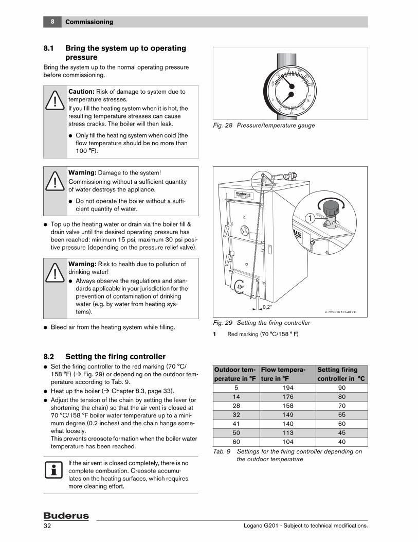
7.1.3 Flue pipe installationFig. 24 shows the proper flue gas connection with addi-tional air equipment.Observe the following during the installation of the flue gas connection:
V Install a flue pipe connection with an inspection aper-ture for cleaning.
V Fasten the flue gas connector piece to the boiler.V Feed the connector into the flue gas system on a short,
ascending path. Avoid deflections, especially those with an angle of 90°.
V Fasten and support connectors sufficiently.V Since the flue pipe is only fixed into the flue gas system
and push-fitted onto the boiler flue socket, it should be fitted very carefully so that it does not come loose.
V Only use parts of non-flammable materials for the flue gas system.
Fig. 24 Position of the additional air equipment
1 Optimal position: additional air equipment in the chimney flank
2 Alternative position: additional air equipment in the flue gas pipe
The figures in Tab. 8 are only guide figures. The draft depends on the diameter, height, roughness of the chimney wall, and the tem-perature difference between combustion products and the outside atmosphere. We recommend the use of a chimney liner.V Have precise calculations carried out by a
heating engineer or flue installer.
Boiler output Flue duct type Minimum height
27 Ø 6.0 inches
Ø 7.0 inches
Ø 8.0 inches
Ø 9.0 inches
at least 26.25 feet
at least 19.5 feet
at least 16.5 feet
at least 16.5 feet
35 Ø 6.0 inches
Ø 7.0 inches
Ø 8.0 inches
Ø 9.0 inches
at least 32.4 feet
at least 26.25 feet
at least 22.95 feet
at least 19.5 feet
40 Ø 7.0 inches
Ø 8.0 inches
Ø 9.0 inches
at least 32.4 feet
at least 29.4 feet
at least 26.25 feet
Tab. 8 Recommended minimum chimney flue heights
7 Installation
Logano G201 - Subject to technical modifications.28
7.2 Making the water connections
7.2.1 Installing B-KitThe pressure relief valve [6] and the pressure/tempera-ture gauge [1] are mounted on the boiler supply VK using the return manifold [5] (included in B-Kit).
V Seal the double nipple [2] with R 1¼ " threads NPT.V Seal 90° 1¼ " NPT street elbow [3] on double nipple.V Seal supply manifold [5] on 90° 1¼ ” NPT elbow [3].
V Seal the temperature/pressure gauge [1] on the sup-ply manifold.
7.2.2 Connecting the water linesV Connect the return to the connection RK.V Connect the supply to the supply manifold.V Seal the fill & drain valve with sealing twine.V Connect the fill & drain valve to the connection EL
( Fig. 26).
Fig. 26 Sealing the fill & drain valve
1 Fill & drain valve
Caution: Risk of system damage due to leaking connections!V Support the pipes to the boiler to prevent
them from being under stress.
Do not install the pressure relief valve [6] until the leak test ( Chapter 7.3, page 29) has been completed.The pressure relief valve must be installed in a vertical position.
Caution: System damage due to condensa-tion and tar formation!The life span of the boiler can be compro-mised.
V The return temperature must be at least 131 °F, and the boiler water temperature between 176 and 194 °F.
V Install a thermostatic valve that prevents the return flow temperature from dropping below 131 °F (return temperature boost-er).
7Installation
Logano G201 - Subject to technical modifications. 29
7.3 Filling the heating system and checking connections for leaks
Before commissioning the heating system, check it for soundness to avoid leaks occurring during operation.
Carry out the leak test at 1.5 times the normal operating pressure and in accordance with the local regulations:
Warning: Risk to health due to pollution of drinking water!V Always observe the regulations and stan-
dards applicable in your jurisdiction for the prevention of contamination of drinking water (e.g. by water from heating sys-tems).
Warning: Risk of system damage from ex-cessive pressure!Pressure, control, and safety equipment and the DHW cylinder may be damaged by ex-cessive pressure.
V When you carry out a leakage test, make sure that no pressure, control or safety equipment that cannot be isolated from the boiler water chamber is installed.
Caution: Risk of damage to system due to temperature stresses.If you fill the heating system when it is hot, the resulting temperature stresses can cause stress cracks. The boiler will then leak.
V Only fill the heating system when cold (the flow temperature should be no more than 100 °F).
7 Installation
Logano G201 - Subject to technical modifications.30
V Seal pressure relief valve connection ( Fig. 25, page 28) and all other open connection with blind plugs.
V Isolate the expansion tank from the system by closing the valve.
V Open the mixing and shut-off valves on the heating water side.
V Connect the hose to the water tap. Push hose onto the hose connection of the boiler fill & drain valve, fasten with a hose clip, and fill with water.
V Open the fill & drain valve. Slowly fill the heating system. Observe the pressure gauge (pressure/temperature gauge) while doing so.
Fig. 27 Pressure/temperature gauge
V Close the water tap and the boiler fill & drain valve once the required operating pressure has been reached.
V Check the connections and pipework for leaks.V Bleed the boiler by carefully opening the pressure relief
valve on the manifold.V Bleed the heating system via the purge valves on the
boiler piping.V Replenish with water if the pressure drops as a result
of bleeding the system.V Remove the hose from the boiler fill & drain valve. V Installing the pressure relief valve ( Fig. 25, page 28)
8Commissioning
Logano G201 - Subject to technical modifications. 31
8 CommissioningThis chapter explains how to commission the heating sys-tem for the first time.
V Complete the commissioning report during this pro-cess ( Chapter 8.6, page 36).
Danger: Risk of fatal accident due to chim-ney fire!V Before initial commissioning, have the
chimney checked by the local chimney in-staller.
V If soot ignites, close all ventilation ducts to the boiler and the fuel space door.
V Check flue pipe for leaks.V Do not make any constructional changes
to the boiler.
Warning: System damage and risk of injury in case of incorrect commissioning!V Only have the appliance installed or al-
tered by an approved heating contractor.V Before the initial commissioning, check
whether the heating system is filled up with water and bled.
Warning: Risk of injury from open boiler doors!V Do not open the fuel filler door of the boiler
during operation.
Warning: Risk of injury from too-high tem-perature of the flue gas header!V Avoid touching the flue gas header during
operation.
Warning: Risk of system damage due to in-correct operation!V Instruct the customer or system operator
about the operation of the appliance.
8 Commissioning
Logano G201 - Subject to technical modifications.32
8.1 Bring the system up to operating pressure
Bring the system up to the normal operating pressure before commissioning.
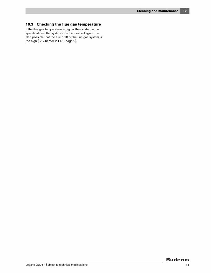
Fig. 28 Pressure/temperature gauge
V Top up the heating water or drain via the boiler fill & drain valve until the desired operating pressure has been reached: minimum 15 psi, maximum 30 psi posi-tive pressure (depending on the pressure relief valve).
V Bleed air from the heating system while filling.Fig. 29 Setting the firing controller
1 Red marking (70 °C/158 ° F)
8.2 Setting the firing controllerV Set the firing controller to the red marking (70 °C/
158 °F) ( Fig. 29) or depending on the outdoor tem-perature according to Tab. 9.
V Heat up the boiler ( Chapter 8.3, page 33).V Adjust the tension of the chain by setting the lever (or
shortening the chain) so that the air vent is closed at 70 °C/158 °F boiler water temperature up to a mini-mum degree (0.2 inches) and the chain hangs some-what loosely.This prevents creosote formation when the boiler water temperature has been reached.
Caution: Risk of damage to system due to temperature stresses.If you fill the heating system when it is hot, the resulting temperature stresses can cause stress cracks. The boiler will then leak.
V Only fill the heating system when cold (the flow temperature should be no more than 100 °F).
Warning: Damage to the system! Commissioning without a sufficient quantity of water destroys the appliance.
V Do not operate the boiler without a suffi-cient quantity of water.
Warning: Risk to health due to pollution of drinking water!V Always observe the regulations and stan-
dards applicable in your jurisdiction for the prevention of contamination of drinking water (e.g. by water from heating sys-tems).
If the air vent is closed completely, there is no complete combustion. Creosote accumu-lates on the heating surfaces, which requires more cleaning effort.
Tab. 9 Settings for the firing controller depending on the outdoor temperature
8Commissioning
Logano G201 - Subject to technical modifications. 33
8.3 Heating up the boiler
V Open the ash pan door.V Turn the bolt [2] of the front grate counter-clockwise to
the stop.V Fold the front grate [1] downwards.
Fig. 30 Folding the front grate downwards
1 Front grate2 Bolt
V Turn the bolt [2] of the segment plate counter-clock-wise to the stop.
V Remove the segment plate [1].
Fig. 31 Removing the segment plate
1 Segment plate2 Bolt
V To increase the draft of the boiler, open the exhaust flap.
Fig. 32 Open the exhaust flap
Warning: Risk of system damage due to in-correct operation! Overfilling the ignition chamber with fuel can cause overheating and damage to the boiler.
V Adjust fuel quantity to the energy absorp-tion of the heating system ( Chapter 8.4, page 35).
Decisive for clean burning in the boiler are the correct operation of the boiler and a suf-ficient flue draft for the flue gas system.
8 Commissioning
Logano G201 - Subject to technical modifications.34
V Insert a layer of paper [2].V Insert a 3 to 4 inch layer of fuel (thin kindling, coal or
coke) on the paper layer [2]. Do not use any thick logs.V Light the fuel inside the boiler. V If you are using solid accelerant (coal igniter), light the
accelerant outside of the boiler and then place it on the ignition material.
V Fold the front grate upwards and insert the segment plate.
V Leave the ash pan door slightly open. V Let the fuel burn for 15 – 20 minutes until there are
embers.V Close the ash pan door.
Fig. 33 Inserting the paper layer and fuel
1 Fuel (e.g. wood)2 Paper layer
V Open the fuel filler door and fill the ignition chamber [1] to ¼ of its volume with fuel.
V Close the fuel filler door.V To prevent heat losses in the chimney, close the
exhaust flap depending on the flue draft ( Fig. 35). If the flue gases are not drawing properly (flue draft is not sufficient), open the exhaust flap a little again ( Fig. 32, page 33).
Fig. 34 Inserting fuel (heating up)
1 Combustion chamber
Fig. 35 Closing the exhaust flap
Before the fuel space [1] is filled, the fuel in-serted must be completely burned off and there must be sufficient embers.
The heating-up time may vary depending on how clean the boiler is, the local conditions, the fuels used, and the weather (low pressure in the flue gas system).
With wood firing, note: logs that are too short and too thick cause uneven burning.V Only use logs of the specified thickness
and length ( Chapter 3.1, page 11).
Large types of anthracite coal and coke burn longer; with too great a quantity of fuel, the output can be reduced. Check and stoke the fire at short intervals.
8Commissioning
Logano G201 - Subject to technical modifications. 35
8.4 Energy absorptionThe energy absorption of the heating system (consisting essentially of boiler and buffer storage) depends on the actual value of the water temperature of the buffer stor-age. For economical operation of the heating system, the fuel quantity used must be adjusted to the respective energy absorption. This way, overheating of the boiler is avoided and pollutant emission is reduced.
8.5 Re-filling fuelDepending on the type and quality of fuel, the burning duration of a boiler filling with nominal output of the boiler is approximately 2 to 4 hours with wood firing and approx-imately 3 to 5 hours with coal firing.
Fig. 36 Re-filling fuel
In order to re-fill fuel or check the fill level:
V Open the fuel filler door a crack and wait approximately 10 seconds so that there is less flue gas in the fuel space. As soon as the flue gas quantity is reduced, open the fuel filler door completely.
V In order to reduce the smoke formation in the boiler room during re-filling, open the exhaust flap ( Fig. 37 above).
V Stoke the fire with a poker and add the desired quantity of fuel.Through regular stoking, even combustion and a con-stant power output of the boiler can be achieved.
V Close the fuel filler door [1] and exhaust flap ( Fig. 37 below).
Fig. 37 Exhaust flap (top: open; bottom: closed)
The combustion is disturbed if the fuel filler door is opened in between. This can cause poor burning and excessive flue gas emis-sion.V If possible, let the fuel burn completely
down.
A quick covering of the embers with fuel re-duces the emission of flue gases from the ig-nition chamber.Note if you are burning wood: only re-fill enough wood that there is a distance of at least 2 inches remaining between the upper-most log and the upper edge of the ignition chamber ( Fig. 36 ).Note if you are burning coal: fill coal up to a height of 12 inches. The best conditions for a coal fire are if the height and width of the fill quantity are equal. On each firing, fill the igni-tion chamber with coal up to the beginning of the fuel fill door.
8 Commissioning
Logano G201 - Subject to technical modifications.36
8.6 Commissioning log
Commissioning work Page Readings taken Comments
1. Fill heating system and check for leaks
– Heating system filling pressure
29
____________ psi
2. Bring the system up to operating pressure
– Bleed heating system
– Test pressure relief valve
– Adjust the expansion vessel pressure( expansion vessel documentation)
_________ psi
3. Check combustion air supply and flue system 26
4. Inform operator, hand over technical documenta-tion
5. Confirm properly-completed commissioning, flue gas temperature and draft
Company stamp/signature/date
9Shutting down the boiler
Logano G201 - Subject to technical modifications. 37
9 Shutting down the boiler
V When shutting down the boiler for a long period (e.g. at the end of the heating season) carefully clean it, since the humidity content of the ashes can cause cor-rosion.
V When there is a risk of frost, protect your heating sys-tem against freezing up. Either empty the water-carry-ing lines or fill up the system with anti-freeze (follow the manufacturer's instructions).
9.1 Shutting down the boiler temporarily
V Allow the boiler to cool.V Open the fuel fill door and clean the ignition chamber.V Open the ash pan door and remove the ash shovel.V Ashes should be placed in a steel container with a
tightly fitting lid, and moved outdoors. Other waste must not be placed in this container.
V Clean the ash pan.V Insert the ash shovel and close the ash pan door.V Close the fuel filler door.
9.2 Shutting down the boiler for a long period
When shutting down the boiler for a long period (e.g. at the end of the heating season) carefully clean it.
9.3 Shutting down the boiler in an emergency
Explain to the customer what to do in an emergency, e.g. in case of an explosion or fire.
V Never put yourself at risk of fatal injury. Your own safety must always take the highest priority.
V Carefully open the fuel filler door.Carefully opening the fuel filler door prevents the flames from leaping out towards you.
V Extinguish the fire with water.
Warning: Risk of system damage due to frost!If the heating system has been shut down, it may freeze up in cold weather conditions.
V When there is a risk of frost, protect your heating system against freezing up.
V If there is risk of frost and you are not operating the boiler, empty the system.
To shut the boiler down, let it burn off every-thing without artificially accelerating the com-bustion process.
10 Cleaning and maintenance
Logano G201 - Subject to technical modifications.38
10 Cleaning and maintenance
V Offer your customer an annual contract covering inspection and demand-dependent service. The work that needs to be included in a maintenance contract is detailed in the inspection and maintenance logs.
10.1 Cleaning the boilerSoot and ash accumulations on the interior walls of the boiler reduce the heat transfer. Insufficient cleaning increases fuel consumption and can cause undesirable pollution of the environment.
The ashes that are created during combustion accumu-late primarily in the fuel space.
V Clean the fuel space regularly every 1 to 3 days.
Warning: Damage to system due to improp-er maintenance! Insufficient or improper maintenance of the boiler can cause damage and void warranty claims.
V Carry out regular, extensive, and profes-sional maintenance of the heating system.
The regular professional maintenance of the heating system maintains its efficiency, guar-antees high reliability, and environmentally-friendly combustion.
The cleaning of the heating system depends on the wood quality and the environmental conditions.
There is an inspection and maintenance log attached to these instructions on page 42.
Only use original Buderus spare parts. Buderus assumes no liability for damage caused by the use of parts not supplied by Buderus.
Danger: Risk of environmental damage due to improper operating state!V Clean the boiler regularly depending on
fuel consumption.
Warning: Risk of system damage due to in-sufficient maintenance and cleaning! Larger quantities of ashes in the fuel space can cause overheating of and damage to the boiler.
V Remove the ashes from the boiler regular-ly.
Do the cleaning before you begin to heat and only when the combustion chamber has cooled off.
Warning: Risk to health due to incorrect op-eration! Opening the fuel filler door while heating causes pressure fluctuations in the boiler and the uncontrolled escape of flue gases.
V Only open the fuel filler door when the boiler is not lit and it has cooled off.
10Cleaning and maintenance
Logano G201 - Subject to technical modifications. 39
10.1.1 Frequent cleaningThe ashes must be removed from the combustion cham-ber/ash pan every 1 – 3 days.
V Open the ash pan door [2].V Fold the front grate downwards and remove the seg-
ment plate ( Fig. 30, page 33, and Fig. 31, page 33). V Tip the combustion residues into the ash pan.V Insert the segment plate and fold the front grate
upwards.V Remove the combustion residues from the ash pan
with the ash shovel [1].
Fig. 38 Cleaning the ash pan
1 Ash shovel2 Ash pan door
10.1.2 Monthly cleaningThe flue gas collector and the collector cleanout ( Fig. 40, page 40) must be checked monthly and cleaned if necessary. Insufficient cleaning can cause damage to the boiler and the voiding of warranty claims.
Hot gas flue, cleaningV Open the fuel fill door [2] and remove the waste steam
plate [1].V Clean ash residues from the hot gas flues with a brush.V Insert the waste steam plate [1] and close the fuel filler
door [2].V Take the steps described under 9.1.1.
Fig. 39 Hot gas flue, cleaning
1 Waste steam plate2 Fuel filler door
Do not place hot ashes in plastic and waste containers.
Warning: Risk of system damage due to in-sufficient maintenance and cleaning!V Clean the heat exchanger heat flues and
the flue gas header regularly.
10 Cleaning and maintenance
Logano G201 - Subject to technical modifications.40
Cleaning the flue gas headerThe flue gas collector [2] is cleaned via the inspection aperture. The inspection aperture is on the bottom of the flue gas collector and is sealed with the cleaning cover [1].
V Unscrew the two wing nuts on the cleaning cover.V Carefully remove the cleaning cover [1].V Remove the combustion residues via the inspection
aperture.V Close the inspection aperture with the cleaning cover
[1]. Check that the gasket is seated correctly.V Screw the cleaning cover [1] back on with two wing
nuts.
Fig. 40 Cleaning the flue gas header
1 Cleaning cover2 Flue gas header
10.2 Checking the operating pressure
Fig. 41 Pressure/temperature gauge
V Checking the operating pressure. If the pressure of the system sinks below 15 psi (1 bar), water must be topped up.
V Add water to the system.V Bleed the heating system.V Check the operating pressure again.
Warning: Risk to health due to pollution of drinking water!V Always observe the regulations and stan-
dards applicable in your jurisdiction for the prevention of contamination of drinking water (e.g. by water from heating sys-tems).
Warning: Risk of system damage due to fre-quent topping up!Depending on water quality, the heating sys-tem may be damaged by corrosion or scaling if you frequently top up the heating water.
V Notify your heating contractor if you find you need to top up your heating system frequently.
V Check the heating system for leaks and proper operation of the expansion vessel.
Establish an operating pressure of at least 15 psi, depending on the system height!
10Cleaning and maintenance
Logano G201 - Subject to technical modifications. 41
10.3 Checking the flue gas temperatureIf the flue gas temperature is higher than stated in the specifications, the system must be cleaned again. It is also possible that the flue draft of the flue gas system is too high ( Chapter 2.11.1, page 9).
10 Cleaning and maintenance
Logano G201 - Subject to technical modifications.42
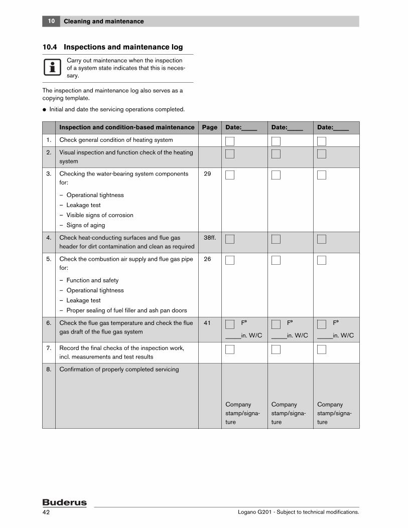
10.4 Inspections and maintenance log
The inspection and maintenance log also serves as a copying template.
V Initial and date the servicing operations completed.
Carry out maintenance when the inspection of a system state indicates that this is neces-sary.
Inspection and condition-based maintenance Page Date:_____ Date:_____ Date:_____
1. Check general condition of heating system
2. Visual inspection and function check of the heating system
3. Checking the water-bearing system components for:
– Operational tightness
– Leakage test
– Visible signs of corrosion
– Signs of aging
29
4. Check heat-conducting surfaces and flue gas header for dirt contamination and clean as required
38ff.
5. Check the combustion air supply and flue gas pipe for:
– Function and safety
– Operational tightness
– Leakage test
– Proper sealing of fuel filler and ash pan doors
26
6. Check the flue gas temperature and check the flue gas draft of the flue gas system
41 F°
_____in. W/C
F°
_____in. W/C
F°
_____in. W/C
7. Record the final checks of the inspection work, incl. measurements and test results
8. Confirmation of properly completed servicing
Company stamp/signa-ture
Company stamp/signa-ture
Company stamp/signa-ture
10Cleaning and maintenance
Logano G201 - Subject to technical modifications. 43
Tab. 10 Inspection and maintenance log (continued)
11 Troubleshooting
Logano G201 - Subject to technical modifications.44
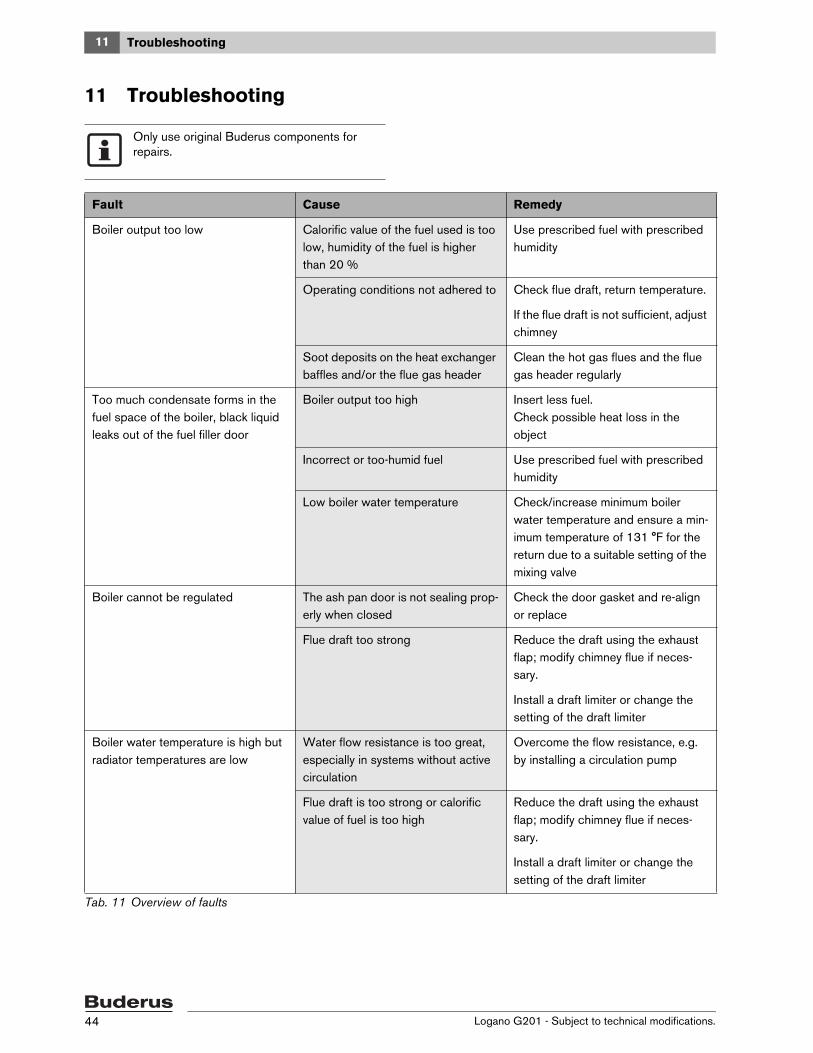
11 Troubleshooting
Only use original Buderus components for repairs.
Fault Cause Remedy
Boiler output too low Calorific value of the fuel used is too low, humidity of the fuel is higher than 20 %
Use prescribed fuel with prescribed humidity
Operating conditions not adhered to Check flue draft, return temperature.
If the flue draft is not sufficient, adjust chimney
Soot deposits on the heat exchanger baffles and/or the flue gas header
Clean the hot gas flues and the flue gas header regularly
Too much condensate forms in the fuel space of the boiler, black liquid leaks out of the fuel filler door
Boiler output too high Insert less fuel.Check possible heat loss in the object
Incorrect or too-humid fuel Use prescribed fuel with prescribed humidity
Low boiler water temperature Check/increase minimum boiler water temperature and ensure a min-imum temperature of 131 °F for the return due to a suitable setting of the mixing valve
Boiler cannot be regulated The ash pan door is not sealing prop-erly when closed
Check the door gasket and re-align or replace
Flue draft too strong Reduce the draft using the exhaust flap; modify chimney flue if neces-sary.
Install a draft limiter or change the setting of the draft limiter
Boiler water temperature is high but radiator temperatures are low
Water flow resistance is too great, especially in systems without active circulation
Overcome the flow resistance, e.g. by installing a circulation pump
Flue draft is too strong or calorific value of fuel is too high
Reduce the draft using the exhaust flap; modify chimney flue if neces-sary.
Install a draft limiter or change the setting of the draft limiter
Tab. 11 Overview of faults
12Parts lists
Logano G201 - Subject to technical modifications. 45
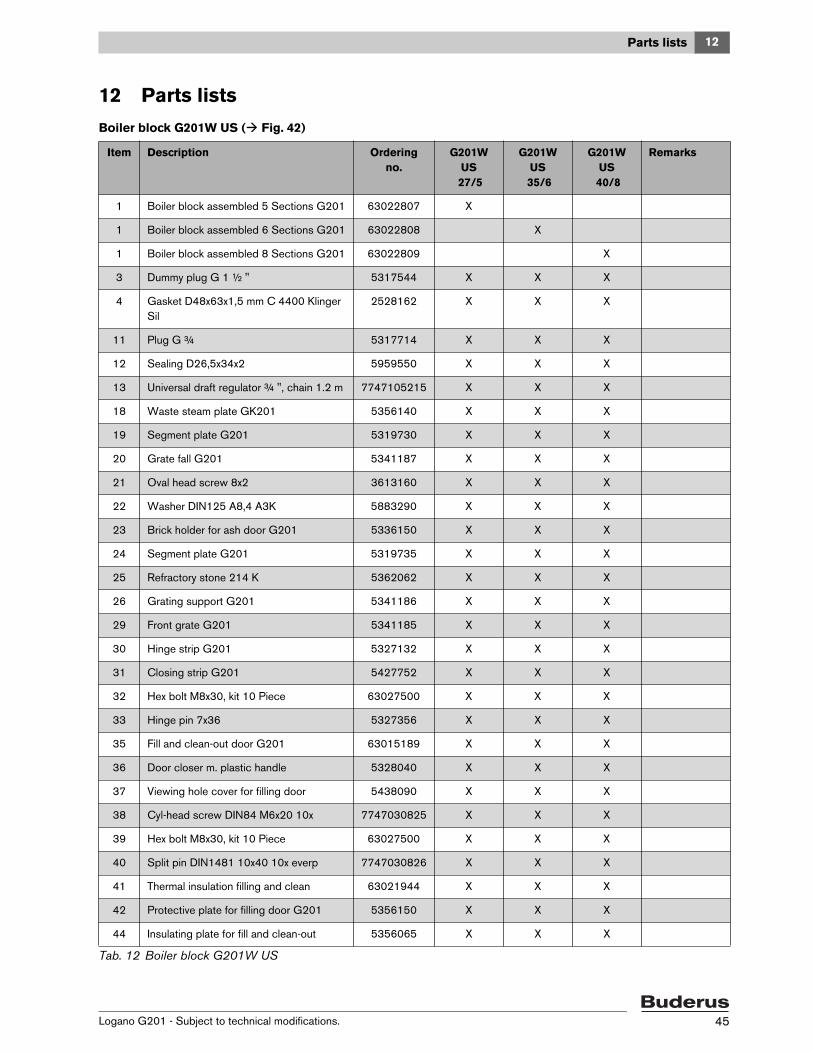
12 Parts lists
Boiler block G201W US ( Fig. 42)
Item Description Ordering no.
G201W US
27/5
G201W US
35/6
G201W US
40/8
Remarks
1 Boiler block assembled 5 Sections G201 63022807 X
1 Boiler block assembled 6 Sections G201 63022808 X
1 Boiler block assembled 8 Sections G201 63022809 X
3 Dummy plug G 1 ½ " 5317544 X X X
4 Gasket D48x63x1,5 mm C 4400 Klinger Sil
2528162 X X X
11 Plug G ¾ 5317714 X X X
12 Sealing D26,5x34x2 5959550 X X X
13 Universal draft regulator ¾ ", chain 1.2 m 7747105215 X X X
18 Waste steam plate GK201 5356140 X X X
19 Segment plate G201 5319730 X X X
20 Grate fall G201 5341187 X X X
21 Oval head screw 8x2 3613160 X X X
22 Washer DIN125 A8,4 A3K 5883290 X X X
23 Brick holder for ash door G201 5336150 X X X
24 Segment plate G201 5319735 X X X
25 Refractory stone 214 K 5362062 X X X
26 Grating support G201 5341186 X X X
29 Front grate G201 5341185 X X X
30 Hinge strip G201 5327132 X X X
31 Closing strip G201 5427752 X X X
32 Hex bolt M8x30, kit 10 Piece 63027500 X X X
33 Hinge pin 7x36 5327356 X X X
35 Fill and clean-out door G201 63015189 X X X
36 Door closer m. plastic handle 5328040 X X X
37 Viewing hole cover for filling door 5438090 X X X
38 Cyl-head screw DIN84 M6x20 10x 7747030825 X X X
39 Hex bolt M8x30, kit 10 Piece 63027500 X X X
40 Split pin DIN1481 10x40 10x everp 7747030826 X X X
41 Thermal insulation filling and clean 63021944 X X X
42 Protective plate for filling door G201 5356150 X X X
44 Insulating plate for fill and clean-out 5356065 X X X
Tab. 12 Boiler block G201W US
12 Parts lists
Logano G201 - Subject to technical modifications.46
45 Sealing twine D12x3100 CS, 63031770 X X X
46 Hex nut DIN6923 M8-A3K with locking gear
5834410 X X X
50 Ash door G201 63015191 X X X
51 Control chain rods M6 63021946 X X X
52 Adjusting bolt for air flap 5337105 X X X
53 Air flap 310 wide for ash door 5337100 X X X
54 Packing cords 6x11x870 Al 63025706 X X X
55 Hinge pin-5 x315 7747105216 X X X
56 Thermal insulation 20x300x320 63021945 X X X
57 Sealing twine D12x3100 CS, 63031770 X X X
58 Protective plate for ash door Log.02.2 5356245 X X X
60 Ash spade 400mm long G201 63018634 X
60 Ash spade 600mm long G201 63018635 X X
Sealing material brown (cartridge 310 ml) 63014361 X X X
Item Description Ordering no.
G201W US
27/5
G201W US
35/6
G201W US
40/8
Remarks
Tab. 12 Boiler block G201W US
12Parts lists
Logano G201 - Subject to technical modifications. 47
Fig. 42 Boiler block G201W US
6720905317.aa.RS
35
36
41
4241
44
45
46
46
52
36
40
40
55
3837
32
5453
5657
58
51
6050
26
29
22
2232
32
3
3
4
4
19
18
2021
2524
32
32
3232
32
32
22
22
33
30 32
30
31
32
3333
33
32
2320
21
1
32
13
12 Parts lists
Logano G201 - Subject to technical modifications.48
Fittings rear ( Fig. 43)
Item Description Ordering no. G201W US
27/5
G201W US
35/6
G201W US
40/8
Remarks
1 Flue gas header 180D G201 5321032 X X X
2 Flue gas cover 180D 5322010 X X X
3 Installation material flue gas cover 63027498 X X X
4 Bearing clamp for Flue gas header G201 9523500 X X X
5 Clean-out cover 5371220 X X X
6 Wing nut DIN315-C M8 CUZn 2915190407 X X X
7 Washer DIN125 A8,4 A3K 5883290 X X X
8 Packing cords GP 7x1000 63020960 X X X Cut to length of 405 mm
9 Stud DIN939-M8x25-5.6 3719060 X X X
10 Sealing 7x2000 GP 7747031101 X X X Cut to length of 1140 mm
13 Flange 1 1/4 NPT square110 everp 7747030510 X X X
14 Gasket D 72x96x1.5 mm 2515124 X X X
15 Stud DIN939 M10x35 5.6 5555060 X X X
16 Hexagon nut DIN6923 M10 8,8 A3K SW16 mm
5834414 X X X
17 Washer DIN125-st 10,5x2,0 mm 82867140 X X X
18 Stud DIN939 M10x40 5.6 3719128 X X X
20 Blind plug G1 1/4 rh, forged version 6073312 X X X
21 Sealing d41,7x55x1,5 4x everp 7747030780 X X X
25 Plug 1/2" 2x everp 7747030774 X X X
26 Reducing nipple G1"xG3/4" everp 7747030786 X X X
27 Gasket D33x44x2 mm 63005462 X X X
29 Feed pipe G201 5436050 X X X
Fixing clamp P 168 /Mecano/ 5436080 X X X
Sealing material brown (cartridge 310 ml)
63014361 X X X
Tab. 13 Fittings rear
12Parts lists
Logano G201 - Subject to technical modifications. 49
Fig. 43 Fittings rear
6720905318.aa.RS
9
9
10
1817
16
13
15
14
10
10
10
10
9
7
5
8
613
15
14
29
1
212520
2120
3
24
4
2726
12 Parts lists
Logano G201 - Subject to technical modifications.50
Tank jacket (Fig. 44)
Item Description Ordering no.
G201W US
27/5
G201W US
35/6
G201W US
40/8
Remarks
1 Side panel L.h. 615 long 63021709 X
1 Side panel L.h. 715 long 63021710 X
1 Side panel L.h. 915 long 63021711 X
2 Side panel R.h. 615 long 63021704 X
2 Side panel R.h. 715 long 63021705 X
2 Side panel R.h. 915 long 63021706 X
3 Tie-bar front G201 63024310 X X X
4 Rear panel 63021712 X X X
5 Tie-bar rear 63021713 X X X
6 Single membrane nipple S4-390 5317684 X X X
7 Hood front 3-8 Sections 63021714 X X X
8 Hood rear 357 long 5 Section 63021717 X
8 Hood rear 457 long 6 Sections 63021718 X
8 Hood rear 657 long 8 Sections 63021719 X
9 Cover G201 63021720 X X X
10 Device label Logano G201 63018113 X X X
11 Protect border G201 7747105214 X X X
13 Installation material for Casing G201 9523818 X X X
Insulating felt 40 mm/2 qm RG15 63020656 X X X for the screen
Insulating felt 60 mm/1 qm RG18 63020657 X X X for the rear panel and hood
Insulating felt 80 mm/1 qm RG18 63020659 X X X for the side panels
Insulating felt 80 mm/2 qm RG18 63020660 X X X for the side panels
Tab. 14 Boiler jacket
12Parts lists
Logano G201 - Subject to technical modifications. 51
Fig. 44 Tank jacket
B u d e r u sLogano G201
6720905319.aa.RS
2
7
8
13
13
13
1313
13
13
3
9
5
4
6
1
131311
10
13 Installation examples and electrical connection schemes
Logano G201 - Subject to technical modifications.52
13 Installation examples and electrical connection schemes
Fig. 45 Wood coal boiler with optional dump zone (installation example)
Fig. 46 Wood coal boiler with optional dump zone (example, connection schemes)
6
13Installation examples and electrical connection schemes
Logano G201 - Subject to technical modifications. 53
Fig. 47 Wood coal boiler with gas/oil boiler (installation example)