20
ATTENTION: READ THE ENTIRE INSTRUCTION SHEET BEFORE STARTING THE INSTALLATION PROCESS. INSTALLATION AND OPERATION INSTRUCTIONS EVOLUTION VIDEO DISTRIBUTION SYSTEM

ATTENTION: READ THE ENTIRE INSTRUCTION SHEET BEFORE STARTING THE INSTALLATION PROCESS.
INSTALLATION AND OPERATION INSTRUCTIONSEVOLUTION VIDEO DISTRIBUTION SYSTEM

2
• DonotbegintoinstallyourEvolutionVideoDistributionSystemuntilyouhavecompletelyreadandunder-standtheseinstructions.
• Thissystemshouldonlybeinstalledbysomeonewhohasgoodmechanicalandelectricalknowledge.
• Nevermountcomponentsnearwaterorwheretheycouldcomeintocontactwithwater.
• Undernocircumstancesshouldanycomponentbetamperedwith.Allwarrantiesstatedorimpliedarevoidifthecomponenthasbeenopenedbyanyoneotherthananapprovedrepairfacility.
WARNING!
Thefollowingisalistofcomponentwhichmaybeincludedwiththesystem.Becauseeachinstallationiscustomdesignedforthecustomer,thislistisareferenceonlytohelpidentifythecomponentsshownontheschematic.
PART IDENTIFICATION LIST
PART HARDWARE PART NAME QUANTITY
A FrontDeskInterface
B AuxiliaryControlModule
C Amplifier
+15vdc
600mA
OUTPUT
INPUT
RF distribution amp 59-1000MHz +18dB
D Modulatorselect program
IR
pll frequency control
A B C D
model 5545 quad digital modulator with ir output
LEGACY SCORING UPGRADEEVOLUTION
FRONT DESK CONTROL MODULE
COMMIN
COMMSTATUS
COMMOUT
5V DC
POWERSTATUS
IRRECEIVE

3
E 2-WaySplitter
F 3-WaySplitter
4-WaySplitterG
H 8-WaySplitter
I 16-WaySplitter
J CoaxSurgeProtector
K Attenuator3db
6db

4
P IREmitter
L RG-6CableEnd
COMMCable(25ft)N
O COMMCable(_______ft)
WallTransformerQ
USB CableR
M RG-6 Cable
InstallationSoftwareS 1

5
Toolsrequiredforinstallation:• CoaxialCableFittingCrimper(Included)• CoaxialCableStripper(Included)
Step1:
Thefirststepwheninstallingthevideodistributionsystemistocarefullyreviewtheincludedschematicandensurethatallpartsspecifiedhavebeeninincludedwiththekit.
Next,noteanyspecialinstructionsontheschematic.Specifically,wherecertaincomponentsaretobeplacedorifcablesneedtobemadetoaspecificlength.ThevideodistributionsystemhasbeencustommadeforthecustomerandtheseinstructionsarecriticaltoensureproperperformanceandanadequatesupplyofRG-6Ucablehasbeenincludedwiththekit.
Reviewtheinstructionsincludedwiththecrimpingandstrippingtools.Manyconnectionsmustbemadeandproperinstallationofthecableendsisimportantforpropersystemperformance.
Notes:• Nevermountcomponentswheretheymaycomeintocontactwithwaterordirectsourcesofheat.• Becarefulwhenpullingcablethroughceilingsorwallsthatitdoesnotbecomefrayedorcut.• Duringinstallationitisgenerallyeasiesttostartatthevideodestination(overheadmonitors)andwork
backtowardthesource(typicallythefrontdesk).• Itisbesttosecureallsplitterstothebuildingstructure.• IfmoreRG-6Ucableendsarerequired,anyreadilyavailableweatherproofCOMPRESSIONfittingthatis
similartotheonesincludedcanbeused.BesuretoNOTbuyendsfor“QuadShield”cableandthattheyaredesignedforRG-6UcableandnotRG-59oranothervariant.AdditionalendscanalsobepurchasedfromD&JMarketing.
Step2:IfaspecificlengthofRG-6Uwasspecifiedontheschematicbeginbybuildingthesecables.Buildingallthecablesatoncewillmaketheprocessgofaster.Thesearegenerallylimitedto12ftcablesbetweenthemonitorsandsplitterasshownbelow.
BegininstallationbyrunningtheRG-6Ucablefromthemonitorstothefirstsplitterfromthemonitor.Thesplittershouldbelocatedinthecenterbetweenthefour(4)monitorsthatitconnectsto.
select program
IR
pll frequency control
A B C D
model 5545 quad digital modulator with ir output
INOUT OUT
OUT OUT
INOUT OUT
OUT OUT
INOUT OUT
OUT OUT
INOUT OUT
OUT OUT
INOUT OUT
OUT OUT
INOUT OUT
OUT OUT
IN
OUT OUT
OUT
IN IN
+15vdc
600mA
OUTPUT
INPUT
RF distribution amp 59-1000MHz +18dB
InstallTheseLinesFirst
6
COMBINERSPLITTER
IN OUT
IN OUT IN OUT
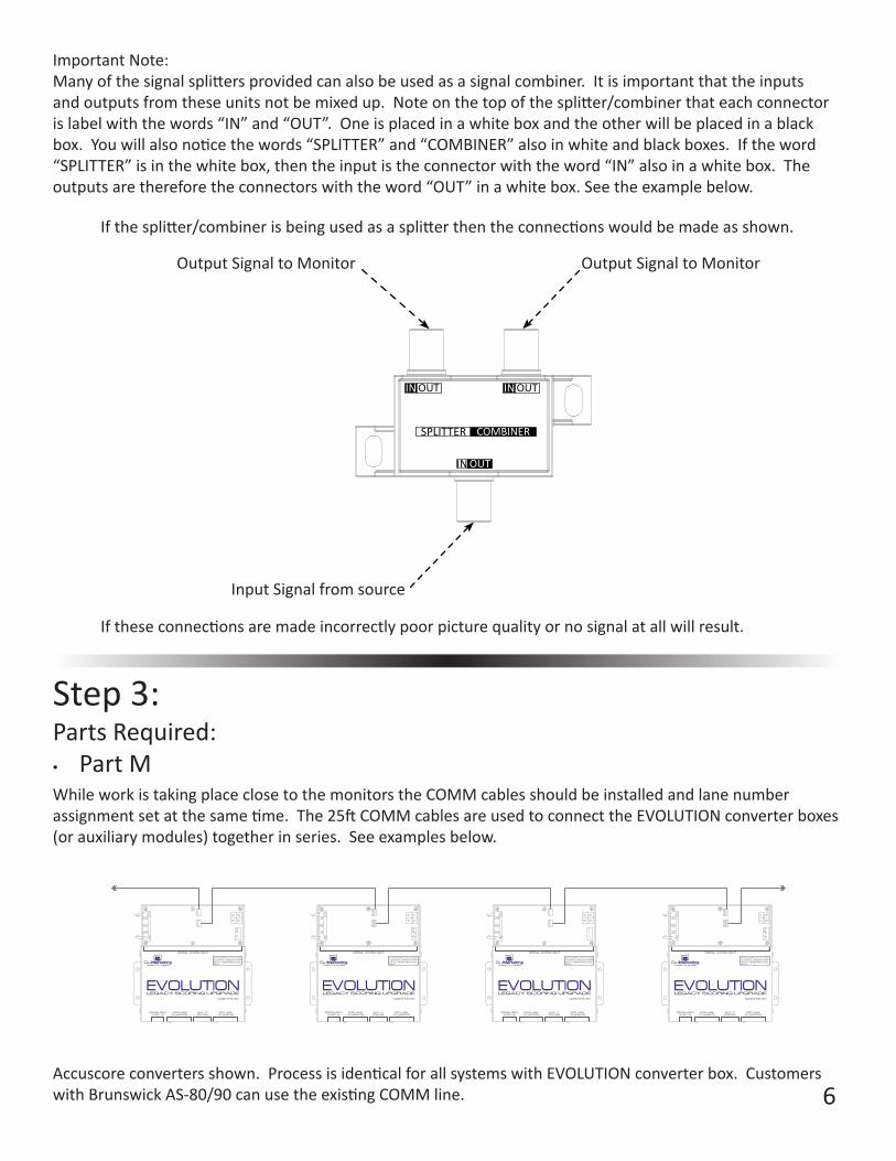
Ifthesplitter/combinerisbeingusedasasplitterthentheconnectionswouldbemadeasshown.
InputSignalfromsource
OutputSignaltoMonitor OutputSignaltoMonitor
Iftheseconnectionsaremadeincorrectlypoorpicturequalityornosignalatallwillresult.
ImportantNote:Manyofthesignalsplittersprovidedcanalsobeusedasasignalcombiner.Itisimportantthattheinputsandoutputsfromtheseunitsnotbemixedup.Noteonthetopofthesplitter/combinerthateachconnectorislabelwiththewords“IN”and“OUT”.Oneisplacedinawhiteboxandtheotherwillbeplacedinablackbox.Youwillalsonoticethewords“SPLITTER”and“COMBINER”alsoinwhiteandblackboxes.Iftheword“SPLITTER”isinthewhitebox,thentheinputistheconnectorwiththeword“IN”alsoinawhitebox.Theoutputsarethereforetheconnectorswiththeword“OUT”inawhitebox.Seetheexamplebelow.
Step3:PartsRequired:• Part MWhileworkistakingplaceclosetothemonitorstheCOMMcablesshouldbeinstalledandlanenumberassignmentsetatthesametime.The25ftCOMMcablesareusedtoconnecttheEVOLUTIONconverterboxes(orauxiliarymodules)togetherinseries.Seeexamplesbelow.
LEGACY SCORING UPGRADEMADE IN THE USA
POWER INPUT5 VDC 1 A
EVEN LANETO MONITOR
ODD LANETO MONITOR
AUX TVCONTROL
CHARLOTTE, MI 48813
ORIGINAL SYSTEM INPUT
THIS DEVICE COMPLIES WITH PART 15 OF THE FCC RULES. OPERATION IS SUBJECT TO THE FOLLOWINGTWO CONDITIONS: ( 1 ) THIS DEVICE MAY NOT CAUSEHARMFUL INTERFERENCE, AND (2) THIS DEVICE MUSTACCEPT ANY INTERFERENCE RECIEVED, INCLUDINGINTERFERENCE THAT MAY CAUSE UNDESIREDOPERATION
EVOLUTIONLEGACY SCORING UPGRADE
MADE IN THE USA
POWER INPUT5 VDC 1 A
EVEN LANETO MONITOR
ODD LANETO MONITOR
AUX TVCONTROL
CHARLOTTE, MI 48813
ORIGINAL SYSTEM INPUT
THIS DEVICE COMPLIES WITH PART 15 OF THE FCC RULES. OPERATION IS SUBJECT TO THE FOLLOWINGTWO CONDITIONS: ( 1 ) THIS DEVICE MAY NOT CAUSEHARMFUL INTERFERENCE, AND (2) THIS DEVICE MUSTACCEPT ANY INTERFERENCE RECIEVED, INCLUDINGINTERFERENCE THAT MAY CAUSE UNDESIREDOPERATION
EVOLUTION
Accuscoreconvertersshown.ProcessisidenticalforallsystemswithEVOLUTIONconverterbox.CustomerswithBrunswickAS-80/90canusetheexistingCOMMline.

7
Note:Besurethatallconnectorsareassembledintheorientationshown.Damagetoequipmentcouldoccurifassembledincorrectly.
• Notetheorientationoflatchfeatureoncableend.• AlignlatchoncableendtolatchonEvolutionboardconnector.• Alsobesureallpinsontheconnectorareengagedwithwiring
harness.Besurenottoinstallconnectorwithpinsshiftedfromsidetoside.
YES NO
ConnectorInstall
ON 1 3 4 52 6 7 8
LaneAssignmentExample• TheEvolutionboardisbeingusedtoupgradelanes23and24.Youwouldsetthelaneas-
signmentDIPswitchtolane23.• IfyouwantedtosetaEvolutionboardtolane23,youwouldsettheDIPswitchasshown.
Lane No. SW 1 SW 2 SW 3 SW 4 SW 5 SW 6 SW 723 ON ON ON OFF ON OFF OFF
Note:Alwayssetswitch8toONwhenusingtheVideoDistributionSystem.Note:Switch1maychangedependingonCPUboardfrequencyonAS-80/90systems.
Lane No. SW 1 SW 2 SW 3 SW 4 SW 5 SW 6 SW 7 Lane No. SW 1 SW 2 SW 3 SW 4 SW 5 SW 6 SW 71 ON OFF OFF OFF OFF OFF OFF 65 ON OFF OFF OFF OFF OFF ON3 ON ON OFF OFF OFF OFF OFF 67 ON ON OFF OFF OFF OFF ON5 ON OFF ON OFF OFF OFF OFF 69 ON OFF ON OFF OFF OFF ON7 ON ON ON OFF OFF OFF OFF 71 ON ON ON OFF OFF OFF ON9 ON OFF OFF ON OFF OFF OFF 73 ON OFF OFF ON OFF OFF ON
11 ON ON OFF ON OFF OFF OFF 75 ON ON OFF ON OFF OFF ON13 ON OFF ON ON OFF OFF OFF 77 ON OFF ON ON OFF OFF ON15 ON ON ON ON OFF OFF OFF 79 ON ON ON ON OFF OFF ON17 ON OFF OFF OFF ON OFF OFF 81 ON OFF OFF OFF ON OFF ON19 ON ON OFF OFF ON OFF OFF 83 ON ON OFF OFF ON OFF ON21 ON OFF ON OFF ON OFF OFF 85 ON OFF ON OFF ON OFF ON23 ON ON ON OFF ON OFF OFF 87 ON ON ON OFF ON OFF ON25 ON OFF OFF ON ON OFF OFF 89 ON OFF OFF ON ON OFF ON27 ON ON OFF ON ON OFF OFF 91 ON ON OFF ON ON OFF ON29 ON OFF ON ON ON OFF OFF 93 ON OFF ON ON ON OFF ON31 ON ON ON ON ON OFF OFF 95 ON ON ON ON ON OFF ON33 ON OFF OFF OFF OFF ON OFF 97 ON OFF OFF OFF OFF ON ON35 ON ON OFF OFF OFF ON OFF 99 ON ON OFF OFF OFF ON ON37 ON OFF ON OFF OFF ON OFF 101 ON OFF ON OFF OFF ON ON39 ON ON ON OFF OFF ON OFF 103 ON ON ON OFF OFF ON ON41 ON OFF OFF ON OFF ON OFF 105 ON OFF OFF ON OFF ON ON43 ON ON OFF ON OFF ON OFF 107 ON ON OFF ON OFF ON ON45 ON OFF ON ON OFF ON OFF 109 ON OFF ON ON OFF ON ON47 ON ON ON ON OFF ON OFF 111 ON ON ON ON OFF ON ON49 ON OFF OFF OFF ON ON OFF 113 ON OFF OFF OFF ON ON ON51 ON ON OFF OFF ON ON OFF 115 ON ON OFF OFF ON ON ON53 ON OFF ON OFF ON ON OFF 117 ON OFF ON OFF ON ON ON55 ON ON ON OFF ON ON OFF 119 ON ON ON OFF ON ON ON57 ON OFF OFF ON ON ON OFF 121 ON OFF OFF ON ON ON ON59 ON ON OFF ON ON ON OFF 123 ON ON OFF ON ON ON ON61 ON OFF ON ON ON ON OFF 125 ON OFF ON ON ON ON ON63 ON ON ON ON ON ON OFF 127 ON ON ON ON ON ON ON
LaneAssignmentTables
Setthelaneassignmentusingtheswitches.SetthisassignmenttotheODDlaneofthetwolanescontrolledbytheEvolutionboard.(Seelaneassignmenttableonnextpage)Important:ThelaneassignmentswitchesmustbechangedwhenpowerisofftotheEvolutionbox.
8
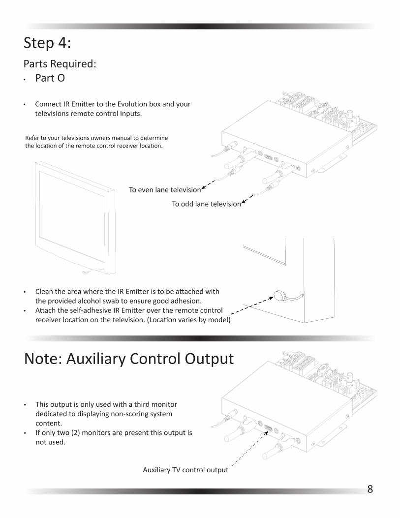
Step4:PartsRequired:• Part O
To even lane television
Tooddlanetelevision
• ConnectIREmittertotheEvolutionboxandyourtelevisionsremotecontrolinputs.
Refertoyourtelevisionsownersmanualtodeterminethelocationoftheremotecontrolreceiverlocation.
• CleantheareawheretheIREmitteristobeattachedwiththeprovidedalcoholswabtoensuregoodadhesion.
• Attachtheself-adhesiveIREmitterovertheremotecontrolreceiverlocationonthetelevision.(Locationvariesbymodel)
Note:AuxiliaryControlOutput
• Thisoutputisonlyusedwithathirdmonitordedicatedtodisplayingnon-scoringsystemcontent.
• Ifonlytwo(2)monitorsarepresentthisoutputisnotused.
AuxiliaryTVcontroloutput
9
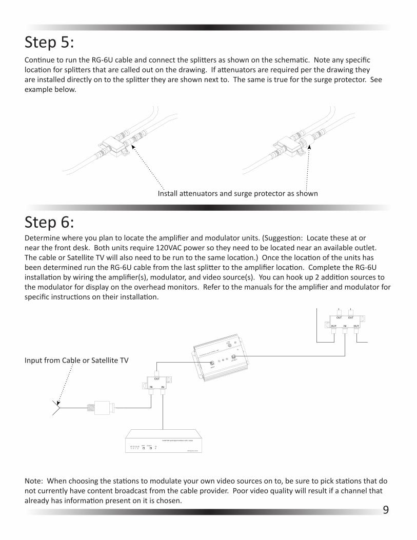
Step5:ContinuetoruntheRG-6Ucableandconnectthesplittersasshownontheschematic.Noteanyspecificlocationforsplittersthatarecalledoutonthedrawing.Ifattenuatorsarerequiredperthedrawingtheyareinstalleddirectlyontothesplittertheyareshownnextto.Thesameistrueforthesurgeprotector.Seeexamplebelow.
Installattenuatorsandsurgeprotectorasshown
Step6:Determinewhereyouplantolocatetheamplifierandmodulatorunits.(Suggestion:Locatetheseatornearthefrontdesk.Bothunitsrequire120VACpowersotheyneedtobelocatednearanavailableoutlet.ThecableorSatelliteTVwillalsoneedtoberuntothesamelocation.)OncethelocationoftheunitshasbeendeterminedruntheRG-6Ucablefromthelastsplittertotheamplifierlocation.CompletetheRG-6Uinstallationbywiringtheamplifier(s),modulator,andvideosource(s).Youcanhookup2additionsourcestothemodulatorfordisplayontheoverheadmonitors.Refertothemanualsfortheamplifierandmodulatorforspecificinstructionsontheirinstallation.
select program
IR
pll frequency control
A B C D
model 5545 quad digital modulator with ir output
INOUT OUT
OUT OUT
INOUT OUT
OUT OUT
INOUT OUT
OUT OUT
INOUT OUT
OUT OUT
INOUT OUT
OUT OUT
INOUT OUT
OUT OUT
IN
OUT OUT
OUT
IN IN
+15vdc
600mA
OUTPUT
INPUT
RF distribution amp 59-1000MHz +18dB
Note:Whenchoosingthestationstomodulateyourownvideosourcesonto,besuretopickstationsthatdonotcurrentlyhavecontentbroadcastfromthecableprovider.Poorvideoqualitywillresultifachannelthatalreadyhasinformationpresentonitischosen.
InputfromCableorSatelliteTV

10
Step7:
RunthelongCOMMcablefromeitherthefirstorlastlanepairinthecenter.RoutethecabletoweretheFrontDeskInterfacewillbelocated.PlugtheCOMMcableintotheFrontDeskInterfaceasshownbelow.
Note:Therearetwo(2)COMMlineconnectorsonthesideoftheFrontDeskControl.MakesurethelongCOMMcablefromthelanesisconnectedtothe“COMMOUT”connector.The“COMMIN”connectorisonlyusedwithBrunswickAS-80/90systems.
Step7b:ThisstepisonlyrequirediftheVideoDistributionSystemisbeingusedwiththeBrunswickAS-80/90system.ConnecttheincludedfrontdeskCOMMCablebetweentheCommandNetworkinterfaceboxandtheFrontDeskControlModule.
HardwareInstallNotes:Atthispointallofthevideodistributionhardwareshouldbeinstalled.Ifdesiredyoumaywanttoinstallanyauxiliaryinputequipment(DVD,VCR,etc)onanylanemonitorsthatisdesired.Doingsonowwillallowthesedevicestobeconfiguredinthesoftwareduringsetup.Thesedevicescanalsobeconfiguredlater.
NOTE:DonotplugintheUSBcablebetweentheFrontDeskControlmoduleandthecomputertillinstructedtodosoafterhesoftwareisinstalled.
11
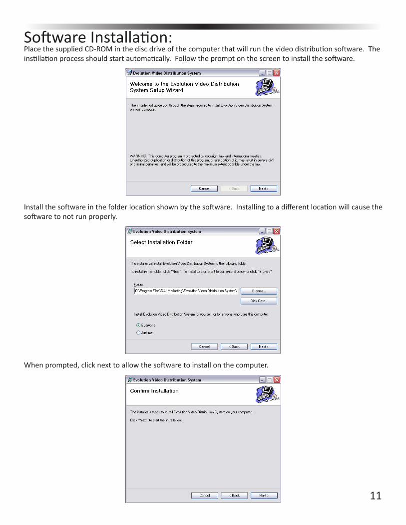
SoftwareInstallation:PlacethesuppliedCD-ROMinthediscdriveofthecomputerthatwillrunthevideodistributionsoftware.Theinstillationprocessshouldstartautomatically.Followthepromptonthescreentoinstallthesoftware.
Installthesoftwareinthefolderlocationshownbythesoftware.Installingtoadifferentlocationwillcausethesoftwaretonotrunproperly.
Whenprompted,clicknexttoallowthesoftwaretoinstallonthecomputer.

12
Oncethescreenbelowappearsthesoftwareinstallationiscompleteandthefrontdeskmodulecanbeconnected.
Step8:InstallthesuppliedpowertransformerbetweentheFrontDeskControlModuleandanavailable120VACwalloutlet.Next,installthesuppliedUSBcablebetweentheFrontDeskControlModuleandanyavailableUSBportonthecomputerwhichwillbeusedfortheVideoDistributionControlsoftware.
Note:OncetheFrontDeskControlModulehasbeenpluggedintopowertheredPowerStatuslightshouldturn on.
13
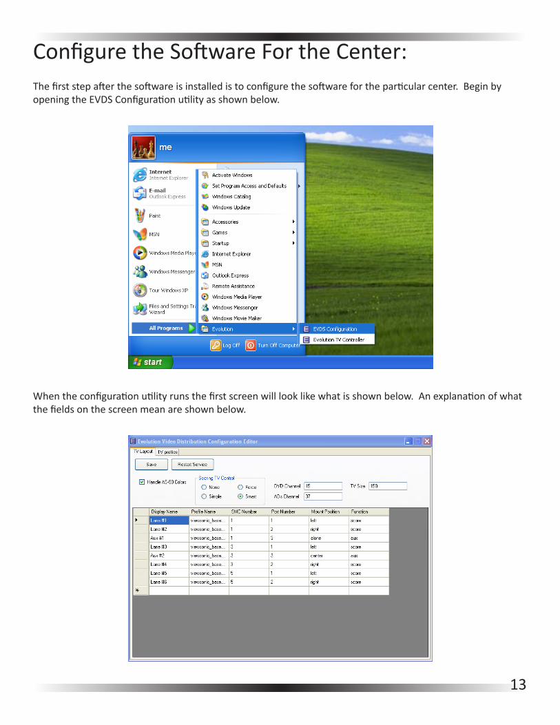
ConfiguretheSoftwareFortheCenter:Thefirststepafterthesoftwareisinstalledistoconfigurethesoftwarefortheparticularcenter.BeginbyopeningtheEVDSConfigurationutilityasshownbelow.
Whentheconfigurationutilityrunsthefirstscreenwilllooklikewhatisshownbelow.Anexplanationofwhatthefieldsonthescreenmeanareshownbelow.

14
• Save:Savesthecurrentconfigurationshowninthedisplaywindow
• Restart Service:Thisrestartsthewindowsserviceandallowsanyconfigurationchangestotakeeffect.
• Handle AS-90 Colors:ThisallowstheEVOLUTIONVideoDistributionsystemtocommunicatetheAS-90
colorinformationtothelaneconverters.OnlyselectthisifusingwithBrunswickAS-90.
• Scoring TV Control
• None:Therewillbenoautomaticcontrolofthelanemonitors.Allcontrolwillhavetobedone
manuallyfromtheVideoDistributiondesktopapplication.
• Simple:LanesMonitorswillturnonandoffautomaticallywiththescoringforaparticularlane.
• Forced:Lanemonitorsareforcedtoscoringmodeanytimescoringisturnedontoalane.When
scoringisturnedoffonthatlanethemonitorwillturnoffregardlessofwhatstateitwasinbefore
scoringwasturnedon
• Smart:Lanemonitorsareforcedtoscoringmodeanytimescoringisturnedontoalane.When
scoringisturnedoffonthatlanethemonitorwillreturntowhateverstateitwasonbeforescoring
wasturnedon.
• DVD Channel:ThisisthechannelthattheDVDplayerismodulatedontothroughthevideomodulatorset
upduringthehardwareinstillation.
• ADS Channel:Thisisthechannelthattheadssourceismodulatedontothroughthevideomodulatorset
upduringthehardwareinstillation.
• TV Size:ThedisplaysizeofthetelevisioniconsontheVideoDistributiondesktopapplication.150isa
goodplacetostart.Iflargericonsaredesiredincreasethenumberinthisfield.Ifsmallericonsaredesired
makethisvaluesmaller.
• Display Name:ThenamethatwillbedisplayedforaparticularmonitorintheVideoDistributiondesktop
application
• Profile Name:Thenameofthetelevisionprofilethatisusedtocontrolthemonitoronthatparticularlane.
• SMC Number:ThelanenumberassignedtotheEVOLUTIONlaneconverterorAuxiliaryControlModuleon
thatparticularlanepair.Note:RememberthatoneEVOLUTIONconvertercontrolsalanepairandpossibly
theAuxiliaryTVsoallmonitorscontrolledbyasingleconverterwillhavethesameSMCnumber.
• Port Number:ThenumberoftheoutputthemonitorisattachedtoontheEVOLUTIONconverteror
Auxiliary Control Unit.
• 1: LabeledasOddLaneontheEVOLUTIONconverterunit
• 2:LabeledasEvenLaneontheEVOLUTIONconverterunit
• 3:LabeledasAuxontheEVOLUTIONconverterunit
• Mount Position:Thisisthepositionthatthemonitorisplaceonthemountasyoulookdownthelane.If
atriplemountisbeingusedthecentermonitormustbelistedascenter,labelingitalonewillcausethe
controlsoftwaretomalfunction.An‘alone’monitorisforstandalonetelevisionsonly.
• Function:Ifthemonitorisusedforbowlingscoringthenthisfieldmustbelistedas‘score’.Ifnoscoringis
usedonamonitorthenthisfieldmustbelistedas‘aux’

15
Step1:Thefirststepistosettheoptionalongthetopoftheconfigurationscreen.
• IftheVideoDistributionSystemisbeingusedwithBrunswickAS-90makesurethecheckboxforhandlingAS-90colorsischecked,otherwiseleaveitunchecked.
• Basedontheexplanationsgivenpreviously,selectthedesiredTVcontrollevelfromtheoptionsgiven.• Inputthechannelswhichanyauxiliaryvideoequipmentaremodulatedontointheprovidedfields.Even
thoughtheyarelistedasDVDandAdsanyvideosourcewhichismodulatedontothecablesignalcanbeused.Rememberwhenconfiguringthemodulatornottouseanychannelswhichalreadyhavevideoinformationonthemorpoorperformancewillresult.
• InputthedesiredsizeoftheTViconsintheVideoDistributiondesktopapplication.Startwiththedefaultvalueshownandadjustasdesired.
Note:AllconfigurationvaluescanbemodifiedatanytimethroughtheEVDSConfigurationutility.
Step2:Nextthetelevisionprofilesneedtobesetup.Profileshavebeenincludedforthemostcommontelevisionswiththesoftware.Itmaybenecessarytomodifyaprofilehoweverdependingonthespecificmodeloftelevisionbeingused.

16
Toviewtheprofilesincludedtryloadingoneoftheprofilesasshownbelowbyselectingthe‘Load’buttonontheTVprofilesscreen.
InthisdirectoryarealloftheincludedTVprofiles.Thisisalsowhereallcustomprofilesshouldbesavedwhentheyarecreated.Ifthebrandoftelevisionbeingusedhasaprofilealreadycreatedthenyoumaynotneedtodoanythingwiththeprofiles.Notetheprofilenamebecauseitwillbeneededtofinishsettingupthecenterconfigurationshortly.Ifyoudonotseethebrandoftelevisionbeingusedthenitwillbenecessarytocreatetheprofile.Itisalsopossiblethataparticularmanufacturermayhavedifferentprofilesdependingontelevisionmodel.Ifmorethanoneprofileforthetelevisionbeingusedispresentthenitmaybenecessarytotryeachonetilltheproperprofileisfound.Itmayalsobenecessarytomodifyanexistingprofileortocreateonefromscratchifthetelevisionbeingusedisnotshowninthelist.ThisprocessisexplainedinAppendixA.
Step3:Thefinalstepintheconfigurationprocessistosetupthecenterlayout.Thelistcreatedmustreadexactlyasthecenterislaidout.WhensettingthelaneassignmentsontheEVOLUTIONconverterunitsorAuxiliaryControlModuleskeepinmindthattheyareassignedtotheODDlanewhichiscontrolledbytheconverter.TheSMCNumbersintheconfigurationwindowmustbelistedinorderfromlowesttohighestandnumberedbytheoddnumberassigned.Itisalsoimportantthatallfieldsbetypedinasshownintheexamplescreen.TheprogramisCASESENSITIVEsoifthetextisshowninlowercaselettersthenitwillonlyexceptlowercaseletters.Theonlyfieldthatthisisnottrueforis‘DisplayName’,thiscanbetypedhoweveritisdesiredtobedisplayedontheVideoDistributiondesktopapplicationmainscreen.Ifaninvalidvalueisenteredintoaparticularfieldthatfieldwillturnredandsavingwillnotbepossible.

17
• EntertheDisplayNamedesiredforaparticularmonitor.• EntertheTVProfileNamenotedearlierexactlyasitisdisplayedintheprofilefolder.NOTE:Theprofile
nameisonlyusedfortheparticulartelevisiononthelineitappears.IftwotelevisionsaredifferenttheywillhavedifferentTVprofilenamesshown.
• EntertheSMCNumberassignedfortheEVOLUTIONconverterorAuxiliaryControlunitforthattelevision.• EnterthePortNumberthatthetelevisionispluggedintoasexplainedearlier.• Enterthemountpositionfortheparticulartelevision.Note:Itisimportantthatthisvaluebecorrectin
orderforthedesktopapplicationtodisplaycorrectly.• EntertheFunctionforthetelevision.Note:Ifthetelevisionwillhavescoringdisplayedthenthisfield
shouldsay‘score’otherwiseitshouldbesetto‘aux’.
Continuetofillintheformforeverytelevisioninthecenter.RememberthatthisformmustreadexactlyasthecenterappearsfromLane1totheotherendofthecenterregardlessofwhichendofthecenterthelongCOMMcableispluggedinto.
Notes:• TheSMCNumbersmustreadfromlowesttohighestbytheoddnumberassigned.Thisincludesany
controlfornon-scoringTV’smountedanywhereinthecenter.• Ifafieldturnsredthenaninvalidvaluehasbeenenteredandmustbecorrectedbeforetheconfiguration
canbesaved.• Thefieldsarecasesensitive.• AnyTVnotdisplayingscoringinformationshouldhaveitsFunctionsetas‘aux’.
Step4:Oncethecenterlayouthasbeencompletedsavetheconfiguration.Oncetheconfigurationhasbeensavedtheservicemustberestartedinorderforthesettingchangestotakeeffect.RestarttheservicebypressingtheRestartServicebuttonontheconfigurationscreen.
Oncetheserviceisrestartedtheconfigurationutilitycanbeclosedbyclickingtheintheupperrighthandcorner.

18
OperatingtheVideoDistributionSystemBeginbystartingtheEVOLUTIONVideoDistributionSystemfromeitherthestartmenuofthedesktopiconasshownbelow.
Oncethesoftwarehasbeenstartedthescreenshouldlooksimilartowhatisshownbelow.ThiswillvarydependingontheconfigurationoftheparticularcentersetuppreviouslyusingtheEVDSConfigurationutility.
Anexplanationofthebuttonfunctionsisgivenonthenextpage.

19
• Select All:Selectsalltelevisionsinthecenter.
• Select Aux:Selectsallauxiliarytelevisionsinthecenter.
• Select Odd:Selectsalloddnumberedtelevisionsinthecenter.
• Select Even:Selectsallevennumberedtelevisionsinthecenter.
• Select None:De-selectsalltelevisionscurrentlyhighlighted.
• Reset:ResetstheEVOLUTIONconverterorAuxiliarycontrolmoduleassociatedwithanyselectedlane.
Note:ThisresetsonlytheEVOLUTIONbox,notthescoringsystem.Noscoringdataislostuponresetwith
thisbutton.
• Remote:Bringsupthevirtualremotecontrolsothatthehighlightedlane(s)canbecontrolledmanually.
Note:Themainprogramdoesnotmonitorthecommandssentfromthevirtualremote,thereforeitwill
notrememberchangesmadewiththevirtualremote.Thisisusedprimarilytofixatelevisionwhichhas
becomeoutofsyncwiththeVideoDistributiondesktopapplication.
• Scoring:Changestheselectedlane(s)toscoringmode.
• Ads:Changestheselectedlane(s)totheAdschannelselectedintheEVDSConfigurationutility.
• Aux:Changestheselectedlane(s)totheauxiliaryinputsetupintheEVDSConfigurationutility.See
AppendixAforsettingupthisfeature.
• DVD:Changestheselectedlane(s)totheDVDchannelselectedintheEVDSConfigurationutility.
• TV:Changestheselectedlane(s)totheTVchannelinputintheTVchannelprompt.
• On:Turnsallselectedtelevisionson.
• Off:Turnsallselectedtelevisionsoff.
IfscoringisturnedonwhentheVideoDistributionserviceisstartedthenthelaneswhichareONwillshowabowlingballandpinsscreenonthetelevision.AllothertelevisionsshouldbeintheOFFstate.Tochangethestatethataparticularlaneorauxiliarytelevisionisinsimplyclickthetelevisiononthescreencorrespondingtothedesiredlaneandselectthedesiredstateofthetelevisionfromthelistofbuttonsexplainedabove.Thepicturesforallstatescanbeseenintheimagebelow.

20
Ifatanytimeoneormorelanepairturnsred(shownbelow)acommunicationproblemwiththatlanepairhasbeendetected.Besurethatthelaneassignmentswitchesareproperlysetforthatlanepair.IfalllanesafterorbeforeacertainpairturnredchecktoseethattheCOMMlinehasnotbecomedisconnectedordamaged.Thedisconnectioncanoccurateitherthefirstlanepairshowinginredoratthefirstpairnoteffectedbythecommunicationerror.
Notes:• Itisrecommendedthatalltelevisionsbeturnedoffusingthedesktopapplicationattheendoftheday.• IfthecomputerrunningtheVideoDistributionsoftwareisrestartedforanyreasonthesoftwarewillnot
rememberwhatstateanytelevisionwasinpreviously.UnlessascoringsignalispresentwhenthesoftwarestartsitwillassumealltelevisionsareOFF.
• IfatelevisionbecomesoutofSync(aka.isONwhenthesoftwarethinksit’sOFF)usethevirtualremotetocorrecttheproblem.
UsingtheVirtualRemote
Thevirtualremoteisgenerallyusedtocorrectoutofsyncproblemsbetweenthetelevisionsandthecontrolsoftware.ItmayalsobeusedtocheckthatanewremotecommandfromtheEVDSConfigurationutilityisworkingasexpected.
• Selectthetelevision(s)thatneedtobecontrolledbythevirtualremote.• Select‘Remote’fromthebuttonsatthetopofthedesktopapplication.• ThevirtualremotecontrolshouldactjustasthefactoryremoteforthatparticularTV.


![Caliper Operation Instructions[1]](https://static.documents.pub/doc/80x56/577cc5701a28aba7119c6424/caliper-operation-instructions1.jpg)


