39
Keeps you cool, warm and powered up! Parks Industries L.L.C. www.hp2000apu.com K-SERIES HP2000 APU Installation and Operator's Manual Manual For HP2000

Keeps you cool, warm and powered up!
Parks Industries L.L.C. www.hp2000apu.com K
-SER
IES H
P2000 A
PU
Installation and Operator's
Manual Manual For HP2000

CONTENTS
Introduction ..........................................................................................................................3
Warranty and Registration .....................................................................................................3
Manual Overview ..................................................................................................................4
Safety ....................................................................................................................................4
System Components Power Unit ............................................................................................5
Power Unit ....................................................................................................................5
Evaporator Assembly .....................................................................................................5
APU Controller (New and Prior Models) ..........................................................................5
Controller Operation ..............................................................................................................6
Legacy Controller ...............................................................................................................7
Climate Control Mode ....................................................................................................7
Battery Monitor Mode ...................................................................................................7
Off Mode .......................................................................................................................7
Oil Timer Reset Procedure ..............................................................................................7
2013 APU Commander .......................................................................................................8
Getting Started ..............................................................................................................8
Stop, Back, More and Settings Buttons ...........................................................................8
Climate Control ............................................................................................................ 13
Battery Monitor ........................................................................................................... 13
Cold storage................................................................................................................. 13
10-Step Installation .............................................................................................................. 14
Step 1: Mounting the APU ................................................................................................ 15
Step 2: Fuel tank draw tube installation ............................................................................ 17

Step 3: evaporator system and Duct Hoses ....................................................................... 18
Step 4: Controller Installation ........................................................................................... 19
Step 5: A/C Line Installation ............................................................................................. 20
step 6: Connecting power cables ...................................................................................... 21
Step 7: Water Connections ............................................................................................... 22
Step 8: Charge the A/C System ......................................................................................... 24
Step 9: System Prime and Safety Check ............................................................................ 26
Priming the water pump .............................................................................................. 26
Connect the control cable ............................................................................................ 26
Step 10: initial start .......................................................................................................... 27
Maintenance ....................................................................................................................... 28
Walk-Around Inspection............................................................................................... 28
Typical Inspection ........................................................................................................ 28
Oil Timer Reset Procedure ............................................................................................ 28
Maintenance Schedule ..................................................................................................... 29
A/C System Maintenance ................................................................................................. 30
Owner’s Responsibility ......................................................................................................... 31
Troubleshooting .................................................................................................................. 32
Warranty Procedure ............................................................................................................ 34
Specifications ....................................................................................................................... 35
Parks Industries LLC HP2000 Installation and Operator’s Manual
2 | P a g e
About Parks Industries LLC
Parks Industries L.L.C. has been in the business of designing and manufacturing auxiliary power
units since 2004. We provide our APU technology to airports, military applications, emergency
vehicles, trucking companies, as well as construction equipment. Our goal is to provide a
quality and efficient auxiliary power unit for all of these industries.
Trademarks
HP2000
Exclusion for Documentation
Unless specifically agreed to in writing, Parks Industries L.L.C.
(A) Makes no warranty as to the accuracy, sufficiency or suitability of any technical
or other information provided in its manuals or other documentation .
(B) Assumes no responsibility or liability for injury, losses, damages, costs or
expenses, whether special, direct, indirect, consequential or incidental, which
might arise out of the use of such information. The use of any such information
will be entirely at the user’s risk .
Revision information
Rev F, 1-2-15.
Manual Product Number
PCM002-01
Contact Information
15460 Crabtree School Rd.
Marion, IL 62959
Toll Free: 1-855-472-0002
Fax: 618-997-9608
www.hp2000apu.com
Parks Industries LLC HP2000 Installation and Operator’s Manual
3 | P a g e
INTRODUCTION
Congratulations on your purchase of your new HP2000 K-Series Auxiliary Power Unit- your fuel and
maintenance savings begin today! As you may already know, the HP2000 consists of a powerful yet lean
Kohler diesel engine along with a revolutionary HVAC system to keep you warm, cool and powered up.
With over a decade in development and on-road testing and usage, the HP2000 Auxiliary Power Unit is
designed specifically for the transportation industry. It is designed and built to handle the extreme
temperatures drivers battle every day. By eliminating the need for the truck’s engine to idle, fuel usage is
reduced significantly while allowing the driver to enjoy all of the comforts that are usually associated with
an idling engine.
WARRANTY AND REGISTRATION
ENGINE WARRANTY
The Kohler Company warrants to the original retail consumer that each new Kohler diesel engine sold will
be free from manufacturing defects in materials or workmanship in normal service for a period of three
years or 3000 hours, whichever comes first from the date of purchase, provided it is operated and
maintained in accordance with Kohler Company’s instructions and manuals. Please refer to your Kohler
engine manual for more details. If no hour meter is installed as original equipment then eight hours of
use per day and five days per week will be used to calculate hours used.
Even though Parks Industries offers engine components for sale, they can’t be used for Kohler Warranty
purposes and will not be reimbursed by Parks Industries, LLC. The components that we offer are for out of
warranty replacement only and are strictly customer pay. To find the nearest Kohler Authorized Warranty
repair center, go to the following web page and follow the instructions: http://www.kohlerengines.com
and click on “Service and Dealer Locator”.
PARKS INDUSTRIES, LLC
Parks Industries, LLC, provides a two year, 2000 hour warranty (whichever comes first) on the following
components: A/C Compressor, Condenser, Condenser Check Valve Assembly, Condenser Fan Assembly,
Evaporator Check Valve Assembly, Auto Controller, Condenser Fan, Evaporator, 12V Evaporator Blower,
Reversing Valve Assembly, Hose & Tube Assembly, High Pressure Switch, Low Pressure Switch and
Compressor Belt. Warranty does not cover: oil, shop supplies, miscellaneous materials, etc. Refrigerant is
only covered if a covered component fails and the refrigerant is lost. Refrigerant is reimbursed as outlined
in the SRT Guide. Parks Industries does not pay miscellaneous supplies and /or Hazardous Material
Charges. Make yourself aware of the maintenance and customer responsibility portion of the manual, lack
of maintenance and neglect are not covered under the warranty. For more information please see the
Policy and Procedures Manual.

Parks Industries LLC HP2000 Installation and Operator’s Manual
4 | P a g e
IMPORTANT! Without registration, your HP2000 is not covered under warranty. It is important
that you have a copy of your registration card.
MANUAL OVERVIEW
This manual covers the topics of installation, operation, general maintenance and troubleshooting for the
HP2000 K-Series APU by Parks Industries.
The patented design of the HP2000 makes it the leader in the auxiliary power unit industry. Its unique
features set it apart from any other unit currently available on the market today. It provides solutions to
many of the problems faced by the transportation industry on a daily basis, yet actually reduces overall
costs. You will immediately notice the fuel savings produced by the HP2000. In addition, the HP2000 saves
wear and tear on major truck components, cuts down on costly oil changes and increases battery life.
By following the proper installation, service and warranty procedures, your new HP2000 will provide years
of comfort and service.
SAFETY
Tips and safety warnings are listed throughout this manual. These tips and safety warnings alone cannot
eliminate all hazards that can occur. Pay close attention to instructions and use common knowledge
during maintenance procedures to prevent unnecessary accidents and injuries.
NOTICE:
Hazards or unsafe practices could result in injury or death.
Persistent inhalation of exhaust fumes may cause serious injury and/or death. Anyone suspected
of suffering from carbon monoxide inhalation should be removed from the hazardous area and
given immediate medical attention.
Exercise extreme caution when working near fuel.
Moving parts can cause severe injury and/or death. Before working on any unit, shut it off, and
be sure that the power supply is disconnected.
If the power is not disconnected the unit could automatically start up without warning. This
could cause serious injury.
Never use the APU to provide power for sensitive electrical or medical equipment.

Parks Industries LLC HP2000 Installation and Operator’s Manual
5 | P a g e
SYSTEM COMPONENTS POWER UNIT
POWER UNIT
The power unit consists of the diesel engine, A/C components and
electrical controls. This unit is typically mounted on the frame rail of the
truck. A/C lines, water lines, power and fuel must all be routed to the APU
in order to provide heating, cooling and battery charging.
In the next section we will discuss the proper installation procedure for
the power unit. Proper installation is critical in guaranteeing proper
operation of the APU system. Installation will vary slightly depending on
the make and model of the truck used.
EVAPORATOR ASSEMBLY
The evaporator is mounted somewhere inside of your cab and provides hot or
cold air depending on your needs. Typically the evaporator is mounted
underneath the bunk. A/C lines and a power supply will need to be routed
from the evaporator to the APU to supply heating and cooling and evaporator
control.
APU CONTROLLER (NEW AND PRIOR MODELS)
The APU controller is the brain of the APU. It is responsible for triggering the
relays which power and control the APU. Both the new and prior versions of the
controller offer fully automatic climate control in which the user sets the
temperature and the APU will heat or cool to maintain it. Both controllers also
track and manage the charging cycle for onboard truck batteries.
Please see the “Controllers” section for more detail and instruction for each
control system.
Parks Industries LLC HP2000 Installation and Operator’s Manual
6 | P a g e
CONTROLLER OPERATION
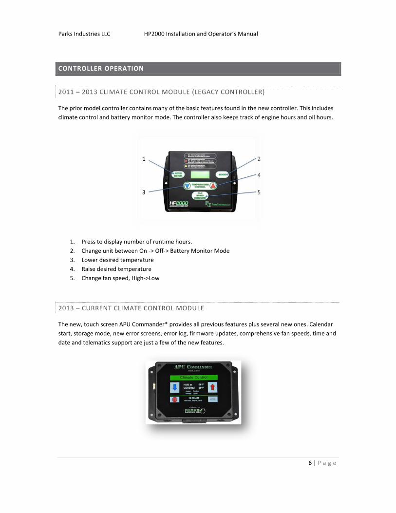
2011 – 2013 CLIMATE CONTROL MODULE (LEGACY CONTROLLER)
The prior model controller contains many of the basic features found in the new controller. This includes
climate control and battery monitor mode. The controller also keeps track of engine hours and oil hours.
1. Press to display number of runtime hours.
2. Change unit between On -> Off-> Battery Monitor Mode
3. Lower desired temperature
4. Raise desired temperature
5. Change fan speed, High->Low
2013 – CURRENT CLIMATE CONTROL MODULE
The new, touch screen APU Commander* provides all previous features plus several new ones. Calendar
start, storage mode, new error screens, error log, firmware updates, comprehensive fan speeds, time and
date and telematics support are just a few of the new features.
Parks Industries LLC HP2000 Installation and Operator’s Manual
7 | P a g e
*See “APU Commander” Section for Controller Operating instructions
LEGACY CONTROLLER
The legacy APU controller provides two different functions: Battery Monitor Mode (Battery Charge Only)
and Climate Control Mode (Charge+Climate). Other features include oil hour meter and unit hour meter.
CLIMATE CONTROL MODE
Press the mode button until the screen reads “Climate Control”. Using the up/down arrow, select your
desired temperature. The APU will automatically enter the startup process. After a short warm-up cycle,
the APU will start and continue to run until the mode button is used to select a different function
Depending on your temperature setting, the APU will heat or cool to achieve the desired temperature.
BATTERY MONITOR MODE
Press the mode button until the screen reads “Battery Monitor Mode”. In this mode, the APU will only run
when the voltage is deemed to be low (Below 12.6V). Once low voltage is detected, the APU will
automatically start and enter a 30 minute charge period. Every thirty minutes the APU will shut down and
check battery voltage. If at the end of three 30 minute periods the battery voltage is still low, the APU will
indicate a charging system failure.
OFF MODE
Pressing the mode button again will disable the unit. The display will read “OFF”. This mode is desired if
the vehicle is entering an extended storage period or if it is in need of service.
OIL TIMER RESET PROCEDURE
Once the oil has reached 600 hours, the display will read, “Oil Change Reqrd”. This indicates that the APU
oil needs changed. Once a service has been performed, it is necessary to reset the oil hour timer. To do
so:
1. Press “Hour Meter” to display oil hours.
2. Press and hold “Hour Meter” and temperature up button for 15 seconds or until the
display reads “Oil Tmr Reset”.
Parks Industries LLC HP2000 Installation and Operator’s Manual
8 | P a g e
2013 APU COMMANDER
The touch screen APU Commander has all of the features described in the Legacy Controller plus many
additional new features.
GETTING STARTED
The APU Commander has three basic functions, Climate Control, Battery Monitor Mode and Storage
Mode. To access these modes, press “Start” and select the desired mode. More details on each mode as
well as other settings can be found in this section.
STOP, BACK, MORE AND SETTINGS BUTTONS
A button labeled “MORE” and “STOP” will be displayed at all times during APU operation. “SETTINGS”
however, will only be displayed when the APU is in the “OFF” mode.
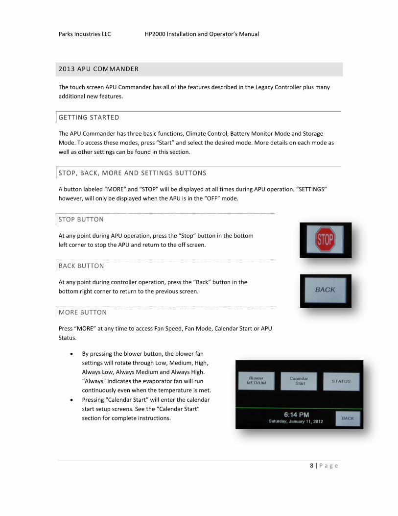
STOP BUTTON
At any point during APU operation, press the “Stop” button in the bottom
left corner to stop the APU and return to the off screen.
BACK BUTTON
At any point during controller operation, press the “Back” button in the
bottom right corner to return to the previous screen.
MORE BUTTON
Press “MORE” at any time to access Fan Speed, Fan Mode, Calendar Start or APU
Status.
By pressing the blower button, the blower fan
settings will rotate through Low, Medium, High,
Always Low, Always Medium and Always High.
“Always” indicates the evaporator fan will run
continuously even when the temperature is met.
Pressing “Calendar Start” will enter the calendar
start setup screens. See the “Calendar Start”
section for complete instructions.

Parks Industries LLC HP2000 Installation and Operator’s Manual
9 | P a g e
Press “Status” to display APU status details and access the error log. See the “Status” section for
complete instructions.
Parks Industries LLC HP2000 Installation and Operator’s Manual
10 | P a g e
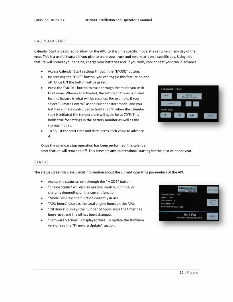
CALENDAR START
Calendar Start is designed to allow for the APU to start in a specific mode at a set time on any day of the
year. This is a useful feature if you plan to store your truck and return to it on a specific day. Using this
feature will preheat your engine, charge your batteries and, if you wish, cool or heat your cab in advance.
Access Calendar Start settings through the “MODE” button.
By pressing the “OFF”” button, you can toggle this feature on and
off. Once ON the button will be green.
Press the “MODE” button to cycle through the mode you wish
to resume. Whenever activated, the setting that was last used
for this feature is what will be recalled. For example, if you
select “Climate Control” as the calendar start mode, and you
last had climate control set to hold at 70°F, when the calendar
start is initiated the temperature will again be at 70°F. This
holds true for settings in the battery monitor as well as the
storage modes.
To adjust the start time and date, press each value to advance
it.
Once the calendar stop operation has been performed, the calendar
start feature will return to off. This prevents any unintentional starting for the next calendar year.
STATUS
The status screen displays useful information about the current operating parameters of the APU.
Access the status screen through the “MODE” button.
“Engine Status” will display heating, cooling, running, or
charging depending on the current function.
“Mode” displays the function currently in use.
“APU hours” displays the total engine hours on the APU.
“Oil Hours” displays the number of hours since the timer has
been reset and the oil has been changed.
“Firmware Version” is displayed here. To update the firmware
version see the “Firmware Update” section.
Parks Industries LLC HP2000 Installation and Operator’s Manual
11 | P a g e
OIL TIMER RESET
You can access the oil timer reset button through the “Status” screen. To reset the oil timer, hold the
“Hold to Reset Oil Timer” button until “APU Oil Hours” goes to 0.
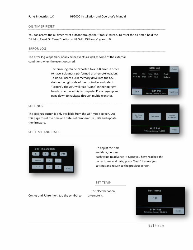
ERROR LOG
The error log keeps track of any error events as well as some of the external
conditions when the event occurred.
The error log can be exported to a USB drive in order
to have a diagnosis performed at a remote location.
To do so, insert a USB memory drive into the USB
slot on the right side of the controller and select
“Export”. The APU will read “Done” in the top right
hand corner once this is complete. Press page up and
page down to navigate through multiple entries.
SETTINGS
The settings button is only available from the OFF mode screen. Use
this page to set the time and date, set temperature units and update
the firmware.
SET TIME AND DATE
To adjust the time
and date, depress
each value to advance it. Once you have reached the
correct time and date, press “Back” to save your
settings and return to the previous screen.
SET TEMP
To select between
Celsius and Fahrenheit, tap the symbol to alternate it.
Parks Industries LLC HP2000 Installation and Operator’s Manual
12 | P a g e
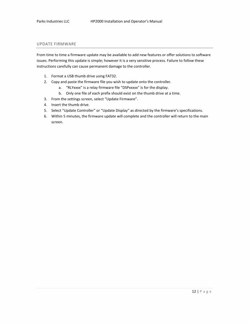
UPDATE FIRMWARE
From time to time a firmware update may be available to add new features or offer solutions to software
issues. Performing this update is simple; however it is a very sensitive process. Failure to follow these
instructions carefully can cause permanent damage to the controller.
1. Format a USB thumb drive using FAT32.
2. Copy and paste the firmware file you wish to update onto the controller.
a. “RLYxxxx” is a relay firmware file “DSPxxxxx” is for the display.
b. Only one file of each prefix should exist on the thumb drive at a time.
3. From the settings screen, select “Update Firmware”.
4. Insert the thumb drive.
5. Select “Update Controller” or “Update Display” as directed by the firmware’s specifications.
6. Within 5 minutes, the firmware update will complete and the controller will return to the main
screen.
Parks Industries LLC HP2000 Installation and Operator’s Manual
13 | P a g e
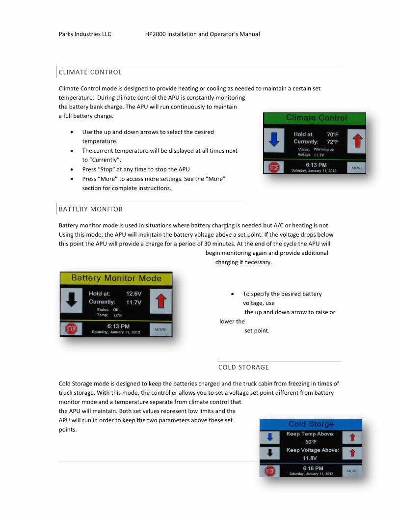
CLIMATE CONTROL
Climate Control mode is designed to provide heating or cooling as needed to maintain a certain set
temperature. During climate control the APU is constantly monitoring
the battery bank charge. The APU will run continuously to maintain
a full battery charge.
Use the up and down arrows to select the desired
temperature.
The current temperature will be displayed at all times next
to “Currently”.
Press “Stop” at any time to stop the APU
Press “More” to access more settings. See the “More”
section for complete instructions.
BATTERY MONITOR
Battery monitor mode is used in situations where battery charging is needed but A/C or heating is not.
Using this mode, the APU will maintain the battery voltage above a set point. If the voltage drops below
this point the APU will provide a charge for a period of 30 minutes. At the end of the cycle the APU will
begin monitoring again and provide additional
charging if necessary.
To specify the desired battery
voltage, use
the up and down arrow to raise or
lower the
set point.
COLD STORAGE
Cold Storage mode is designed to keep the batteries charged and the truck cabin from freezing in times of
truck storage. With this mode, the controller allows you to set a voltage set point different from battery
monitor mode and a temperature separate from climate control that
the APU will maintain. Both set values represent low limits and the
APU will run in order to keep the two parameters above these set
points.
Parks Industries LLC HP2000 Installation and Operator’s Manual
14 | P a g e
To adjust the low temperature limit, set the “Keep Temp Above” using the up and down
arrows.
To set the low voltage limit, set the “Keep Voltage Above” using the up and down arrows.
10-STEP INSTALLATION
INSTALLATION OVERVIEW:
Before beginning installation of your HP2000, take time to inspect the unit and the desired area of
installation. If you believe you are missing a part, please consult the included checklist. Before you begin,
perform an inspection of the truck and installation area. Be sure that all batteries are fully charged and in
good condition. We recommend that you load test your battery bank prior to installation. Take your time
to look over the area where you plan to install the HP2000 and make necessary measurements to ensure
proper installation. Make sure that you have at least 21” of free frame rail space for power unit
installation. Also, make sure you have the necessary space available under the bunk for the evaporator
unit and cable pass through.
Before you get started, un-package your new system and all components. Inspect all components to make
sure they were not damaged during shipping. Examine your truck thoroughly, both inside and out, to
locate the best place to mount the APU. The diesel engine, A/C components and electrical controls are all
contained in the frame-mounted power unit enclosure, which measures 23.5 inches in height, by 19.5
inches in width, by 23 inches in depth. It is important to remember that the APU location should not
interfere with the driver’s access to other vital areas. Also, the location you choose should not crowd any
wires, air or fuel lines that may be nearby.
REQUIRED TOOLS CHECKLIST
IMPORTANT! IT IS IMPERATIVE THAT ALL TOOLS ARE AT THE TRUCK SIDE AND NOT IN YOUR TOOL BOX ACROSS THE SHOP. TO KEEP YOUR INSTALL TIME TO 5 HOURS, YOU MUST HAVE TOOLS AT THE TRUCK.
½” drive ratchet with 15/16” socket Tubing cutter
15/16” wrench 3” hole saw
Hose cutter 3 ½” hole saw
4 hose clamps Battery cable end crimper
7/16” wrench Teflon tape
9/16” wrench Refrigerant leak lock (Part #7012)
Crescent wrench Lift cart or fork truck
Channel locks Torque wrench to tighten mounts on truck
Parks Industries LLC HP2000 Installation and Operator’s Manual
15 | P a g e
¼” nut driver System to vacuum and charge the A/C unit
5/16” nut driver Shop vac
3/8” drive ratchet with 7/16” and ½” socket 1 5/8” hole saw to install controller cable
Wire ties Cut-off wheel
Drill R134-A Refrigerant
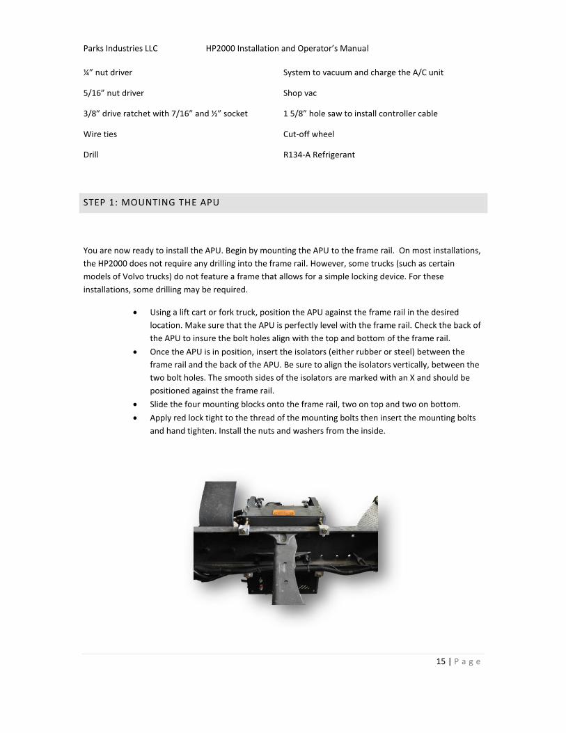
STEP 1: MOUNTING THE APU
You are now ready to install the APU. Begin by mounting the APU to the frame rail. On most installations,
the HP2000 does not require any drilling into the frame rail. However, some trucks (such as certain
models of Volvo trucks) do not feature a frame that allows for a simple locking device. For these
installations, some drilling may be required.
Using a lift cart or fork truck, position the APU against the frame rail in the desired
location. Make sure that the APU is perfectly level with the frame rail. Check the back of
the APU to insure the bolt holes align with the top and bottom of the frame rail.
Once the APU is in position, insert the isolators (either rubber or steel) between the
frame rail and the back of the APU. Be sure to align the isolators vertically, between the
two bolt holes. The smooth sides of the isolators are marked with an X and should be
positioned against the frame rail.
Slide the four mounting blocks onto the frame rail, two on top and two on bottom.
Apply red lock tight to the thread of the mounting bolts then insert the mounting bolts
and hand tighten. Install the nuts and washers from the inside.

Parks Industries LLC HP2000 Installation and Operator’s Manual
16 | P a g e
MAKE SURE THAT THE MOUNTING BLOCKS DO NOT INTERFERE WITH AIR LINES OR WIRING INSIDE THE
FRAME RAIL.
After confirming that the APU is level, tighten the mounting bolts to 80 ft-lbs in an X pattern. Do not
tighten one bolt and then go to the next. Tighten each bolt equally in 10 ft-lb increments, using the X
pattern, until all bolts have the required 80 ft-lbs. If you tighten the bolts completely to 80 ft-lbs the first
time, the unit will become unlevel and internal components will be damaged. While tightening the APU to
the frame, make sure the rubber isolators do not fall out of position.
Parks Industries LLC HP2000 Installation and Operator’s Manual
17 | P a g e
STEP 2: EVAPORATOR SYSTEM AND DUCT HOSES
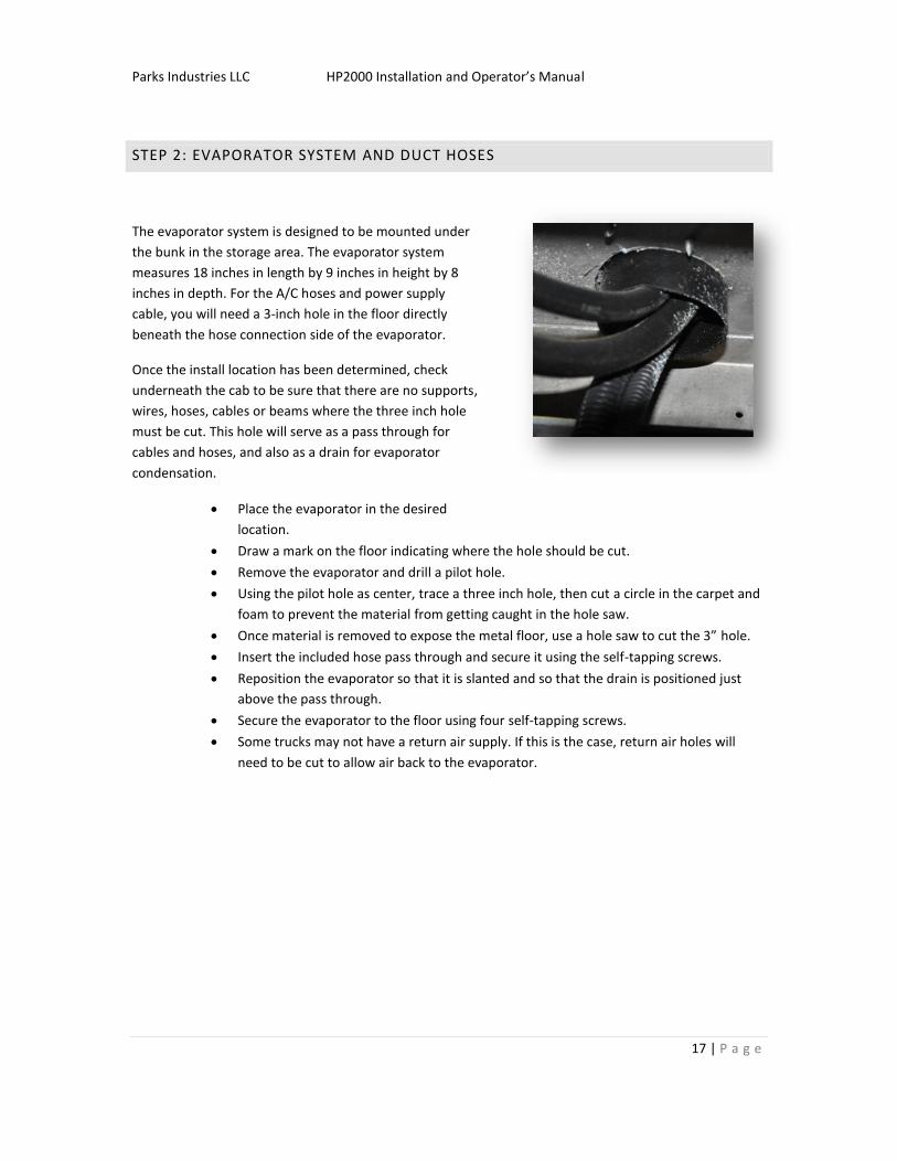
The evaporator system is designed to be mounted under
the bunk in the storage area. The evaporator system
measures 18 inches in length by 9 inches in height by 8
inches in depth. For the A/C hoses and power supply
cable, you will need a 3-inch hole in the floor directly
beneath the hose connection side of the evaporator.
Once the install location has been determined, check
underneath the cab to be sure that there are no supports,
wires, hoses, cables or beams where the three inch hole
must be cut. This hole will serve as a pass through for
cables and hoses, and also as a drain for evaporator
condensation.
Place the evaporator in the desired
location.
Draw a mark on the floor indicating where the hole should be cut.
Remove the evaporator and drill a pilot hole.
Using the pilot hole as center, trace a three inch hole, then cut a circle in the carpet and
foam to prevent the material from getting caught in the hole saw.
Once material is removed to expose the metal floor, use a hole saw to cut the 3” hole.
Insert the included hose pass through and secure it using the self-tapping screws.
Reposition the evaporator so that it is slanted and so that the drain is positioned just
above the pass through.
Secure the evaporator to the floor using four self-tapping screws.
Some trucks may not have a return air supply. If this is the case, return air holes will
need to be cut to allow air back to the evaporator.
Parks Industries LLC HP2000 Installation and Operator’s Manual
18 | P a g e
STEP 3: A/C LINE INSTALLATION
Two A/C lines must be run from the APU to the evaporator in order to supply Freon to the evaporator
unit.
Begin by routing the two 8’ A/C lines through the 3” hole near the evaporator unit as
shown in the figure to the right.
Make sure both hoses are clean and clear of debris and that all connections contain one
O-ring of the appropriate size.
Apply a small dab of leak lock to the threads of the A/C fittings to prevent corrosion and
leakage.
Connect the ends of each hose to the corresponding fitting on the APU.
Connect the supplied check valve to the bottom fitting on the evaporator and connect
the A/C lines from the APU to the corresponding fittings on the evaporator and check
valve.
Once connected, tighten the fittings. Be sure not to over-tighten fittings as this will
damage the O-Rings.
Cable tie all hoses and wires to the frame up and out of the way.
IMPORTANT! DO NOT OVER-TIGHTEN THE A/C LINES,
AS DAMAGE TO O-RINGS MAY OCCOUR.
IMPORTANT! BE CAREFUL NOT TO BEND THE CHECK VALVE DURING INSTALLATION.
IMPORTANT! IT IS SUGGESTED THAT YOU INSTALL THE CONTROL CABLE AT THIS STEP. INSERT
THE ROUND, APU PLUG THROUGH THE HOLE AND ALLOW THE REMAINDER OF THE CONTROL
CABLE TO REMAIN INSIDE THE TRUCK.
Parks Industries LLC HP2000 Installation and Operator’s Manual
19 | P a g e
STEP 4: PULL A VACUUM AND CHARGE THE A/C SYSTEM
Now you are ready to charge the A/C system. Before charging, check to make sure there are no leaks or
system contaminates by pulling a vacuum on the system. We recommend that a 30-minute vacuum
duration be performed to make sure that there are no leaks or moisture in the system.
IMPORTANT! IT IS IMPORTANT TO PULL THAT VACUUM AT THIS POINT IN THE INSTALLTION AS
IT ALLOWS YOU TO CONTINUE WITH THE INSTALL WHILE THE SYSTEM CHECKS FOR LEAKS. THIS
IS IMPERITIVE IN KEEPING TO YOUR 5 HOUR INSTALL TIME.
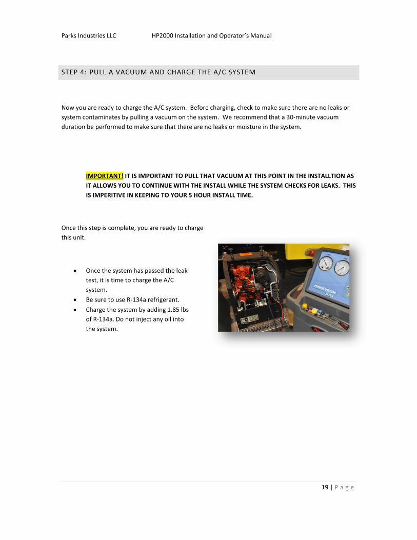
Once this step is complete, you are ready to charge
this unit.
Once the system has passed the leak
test, it is time to charge the A/C
system.
Be sure to use R-134a refrigerant.
Charge the system by adding 1.85 lbs
of R-134a. Do not inject any oil into
the system.
Parks Industries LLC HP2000 Installation and Operator’s Manual
20 | P a g e
STEP 5: FUEL TANK DRAW TUBE INSTALLATION
The fuel block must now be installed in order to provide fuel supply return and tank venting to the APU. It
is important that you DO NOT tie into existing truck fuel lines.
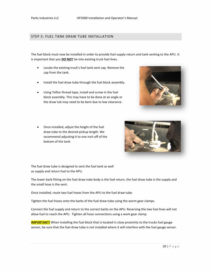
Locate the existing truck’s fuel tank vent cap. Remove the
cap from the tank.
Install the fuel draw tube through the fuel block assembly.
Using Teflon thread tape, install and screw in the fuel
block assembly. This may have to be done at an angle or
the draw tub may need to be bent due to low clearance.
Once installed, adjust the height of the fuel
draw tube to the desired pickup length. We
recommend adjusting it to one inch off of the
bottom of the tank.
The fuel draw tube is designed to vent the fuel tank as well
as supply and return fuel to the APU.
The lower barb fitting on the fuel draw tube body is the fuel return, the fuel draw tube is the supply and
the small hose is the vent.
Once installed, route two fuel hoses from the APU to the fuel draw tube.
Tighten the fuel hoses onto the barbs of the fuel draw tube using the worm gear clamps.
Connect the fuel supply and return to the correct barbs on the APU. Reversing the two fuel lines will not
allow fuel to reach the APU. Tighten all hose connections using a work gear clamp.
IMPORTANT! When installing the fuel block that is located in close proximity to the trucks fuel gauge
sensor, be sure that the fuel draw tube is not installed where it will interfere with the fuel gauge sensor.

Parks Industries LLC HP2000 Installation and Operator’s Manual
21 | P a g e
STEP 6: CONNECTING POWER CABLES
You are now ready to connect the battery cables. Make sure the truck
battery posts are clean, as improper connections could cause the APU
to fail. Always be careful not to reverse polarity of the battery cables
or touch the positive cable to ground. Doing so will cause detrimental
damage to APU, and possibly the truck, and is also a fire hazard.
Route both positive and negative battery cable to the
truck’s battery bank. Cable tie all slack during this
process.
Be extra careful to not let the cables rest on or come in
contact with any moving parts. This could cause a short in
the future.
Once inside the battery compartment, connect the
ground (black) wire to the negative battery post. Do not
connect this to a frame or any other metal for ground.
Prior to connecting the cables to the batteries to the
APU, install the included MRBF fuse onto one of the
positive posts on the battery. This will be the APU
power supply and truck charge supply. This fuse is
necessary to protect against any potential electrical
hazards.
Once the MRBF fuse is installed, connect the positive
(red) lead to the top of the post and tighten the lead
against the fuse. Place the rubber cap over the
connection. Tape if necessary.
Heavy sparking indicates a system short. Do not continue if either
post sparks. Instead, check the integrity of the cable and whether or not
reverse polarity has occurred.
Parks Industries LLC HP2000 Installation and Operator’s Manual
22 | P a g e
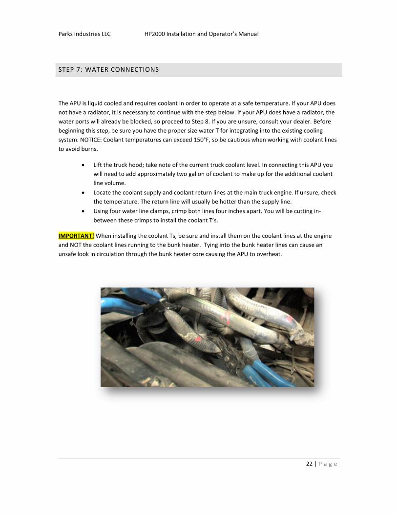
STEP 7: WATER CONNECTIONS
The APU is liquid cooled and requires coolant in order to operate at a safe temperature. If your APU does
not have a radiator, it is necessary to continue with the step below. If your APU does have a radiator, the
water ports will already be blocked, so proceed to Step 8. If you are unsure, consult your dealer. Before
beginning this step, be sure you have the proper size water T for integrating into the existing cooling
system. NOTICE: Coolant temperatures can exceed 150°F, so be cautious when working with coolant lines
to avoid burns.
Lift the truck hood; take note of the current truck coolant level. In connecting this APU you
will need to add approximately two gallon of coolant to make up for the additional coolant
line volume.
Locate the coolant supply and coolant return lines at the main truck engine. If unsure, check
the temperature. The return line will usually be hotter than the supply line.
Using four water line clamps, crimp both lines four inches apart. You will be cutting in-
between these crimps to install the coolant T’s.
IMPORTANT! When installing the coolant Ts, be sure and install them on the coolant lines at the engine
and NOT the coolant lines running to the bunk heater. Tying into the bunk heater lines can cause an
unsafe look in circulation through the bunk heater core causing the APU to overheat.

Parks Industries LLC HP2000 Installation and Operator’s Manual
23 | P a g e
Lay out the supply and return water lines (both at the same time), being careful not to cross
them.
o We recommend marking one of the lines on both ends prior to installation to
prevent accidental crossing. Crossing the lines will cause the APU to overheat.
Connect the supply water line to the bottom fitting on the APU and tighten it to the water
barb using the included ¾” worm gear hose clamps. Remember which line you selected for
supply and which for return.
Connect the return water line to the top fitting on the APU and tighten it to the water barb
using the included ¾” worm gear hose clamps.
Route the hoses to the front of the truck where they will tie in to the water T’s. Be sure that
the hoses are securely cable tied and out of the way.
Once the hoses are secured and pulled into the engine compartment of the truck, determine
the required length to reach the water T’s.
Mark and then trim excess hose.
For one water T at a time:
o Cut the coolant hose between the hose crimpers.
o Install the water T with a hose clamp on each side.
o Tighten the two hose clamps.
o Install a worm gear hose clamp and connect the APU coolant hose to the clamp.
o Tighten the worm gear hose clamp.
Once this has been completed for both T’s, check that the hoses and clamps are tight, and
then remove the hose crimpers.
Parks Industries LLC HP2000 Installation and Operator’s Manual
24 | P a g e
STEP 8: CONTROLLER AND DUCTWORK INSTALLATION
The APU controller is responsible for all functions of the APU. It is important that the controller is
mounted upright, in an area with adequate air flow. Failure to do so will lead to inaccurate temperature
readings and poor performance.
Make sure that the location selected for the controller:
1. Has a clear path to route the control cable.
2. Provides a flat surface for mounting.
3. Has decent air-flow.
Secure the APU controller to the flat surface using the short self-tapping screws. Be careful not to drill into
any other wires or obstacles.
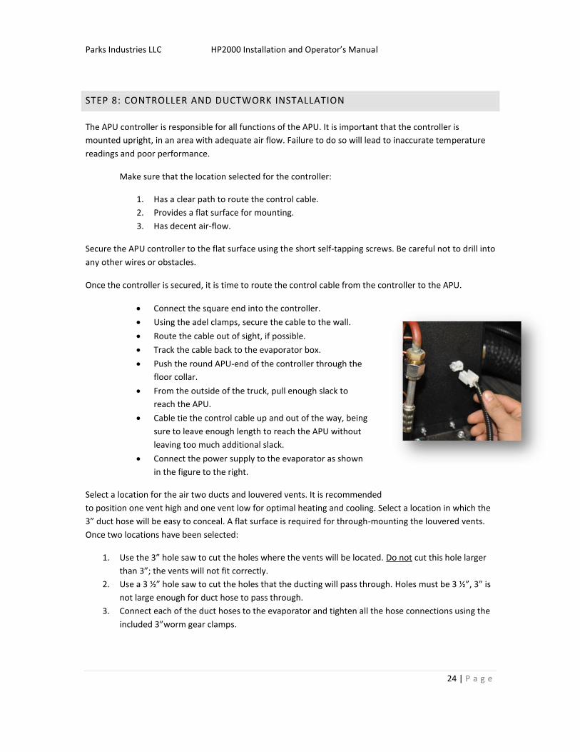
Once the controller is secured, it is time to route the control cable from the controller to the APU.
Connect the square end into the controller.
Using the adel clamps, secure the cable to the wall.
Route the cable out of sight, if possible.
Track the cable back to the evaporator box.
Push the round APU-end of the controller through the
floor collar.
From the outside of the truck, pull enough slack to
reach the APU.
Cable tie the control cable up and out of the way, being
sure to leave enough length to reach the APU without
leaving too much additional slack.
Connect the power supply to the evaporator as shown
in the figure to the right.
Select a location for the air two ducts and louvered vents. It is recommended
to position one vent high and one vent low for optimal heating and cooling. Select a location in which the
3” duct hose will be easy to conceal. A flat surface is required for through-mounting the louvered vents.
Once two locations have been selected:
1. Use the 3” hole saw to cut the holes where the vents will be located. Do not cut this hole larger
than 3”; the vents will not fit correctly.
2. Use a 3 ½” hole saw to cut the holes that the ducting will pass through. Holes must be 3 ½”, 3” is
not large enough for duct hose to pass through.
3. Connect each of the duct hoses to the evaporator and tighten all the hose connections using the
included 3”worm gear clamps.

Parks Industries LLC HP2000 Installation and Operator’s Manual
25 | P a g e
Route the hoses to the vents and tighten all of the hose connections using the included 3”worm gear
clamps..

Parks Industries LLC HP2000 Installation and Operator’s Manual
26 | P a g e
STEP 9: SYSTEM PRIME AND SAFETY CHECK
You are almost ready to start your engine. It is now time to prepare the unit for the initial startup. Be sure
that all tools are clear of the APU and that all connections are tight.
CONNECT THE CONTROL CABLE
Check once again to be sure all tools are removed from the APU and that all connections are tight.
Now that the system has been primed and all connections have been made, you may connect the APU
control cable by twisting it until it locks into place.
PRIMING THE WATER PUMP
It is necessary to run the truck engine for a period of at least five minutes in order to prime the APU water
pump. Not doing so could cause the APU to overheat, causing serious and permanent damage.
IMPORTANT! TO SPEED THE PRIMING PROCESS, YOU MAY REMOVE THE SUPPLY LINE (TOP HOSE) FROM
THE APU UNTIL YOU SEE ENGINE COOLANT START TO FLOW FROM IT. IF YOU USE THIS METHOD TO
PRIME THE APU, BE SURE THAT THE CONTROL CABLE IS FULLY PLUGGED IN OR THAT THE RED, SAFETY
CAP IN INSTALLED. NOT DOING SO CAN CAUSE THE CONTROL CABLE TO SHORT OUT CAUSING SERIOUS
DAMANGE TO THE APU.
The APU is now ready to start.
Parks Industries LLC HP2000 Installation and Operator’s Manual
27 | P a g e
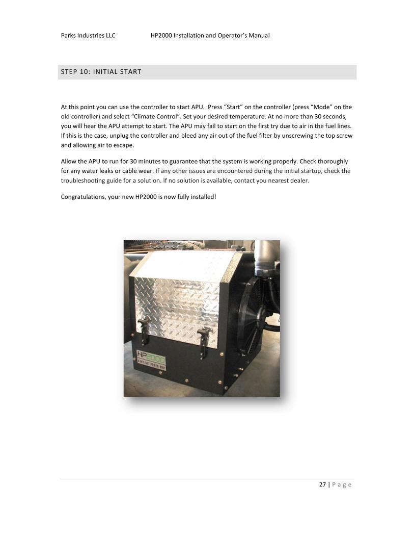
STEP 10: INITIAL START
At this point you can use the controller to start APU. Press “Start” on the controller (press “Mode” on the
old controller) and select “Climate Control”. Set your desired temperature. At no more than 30 seconds,
you will hear the APU attempt to start. The APU may fail to start on the first try due to air in the fuel lines.
If this is the case, unplug the controller and bleed any air out of the fuel filter by unscrewing the top screw
and allowing air to escape.
Allow the APU to run for 30 minutes to guarantee that the system is working properly. Check thoroughly
for any water leaks or cable wear. If any other issues are encountered during the initial startup, check the
troubleshooting guide for a solution. If no solution is available, contact you nearest dealer.
Congratulations, your new HP2000 is now fully installed!
Parks Industries LLC HP2000 Installation and Operator’s Manual
28 | P a g e
MAINTENANCE
By following service and warranty procedures, your new HP2000 will provide years of comfort and
service. Please pay close attention to the directions for each procedure listed below.
WALK-AROUND INSPECTION
This inspection should only take a few minutes. A walk around should be performed during your daily pre-
trip inspection. Perform this inspection to ensure maximum service life of your HP2000. Keep an eye out
for things such as leaks, loose bolts and worn belts and service your APU accordingly.
TYPICAL INSPECTION
After the initial break in period it is important to check all A/C connections. Although the unit is leak
tested at the factory, heat and strong vibrations can loosen certain components. Most A/C leaks are the
result of improperly tightened components and are the responsibility of the installer. In addition, all fluid
levels, coolant and oil should be checked. Electrical connections, cables and hoses should also be checked
before operating the APU.
OIL TIMER RESET PROCEDURE
Depending on which controller you have, the oil timer reset procedure may vary. Check the “Controller
Operation” section for your controller to determine the proper procedure.
Parks Industries LLC HP2000 Installation and Operator’s Manual
29 | P a g e
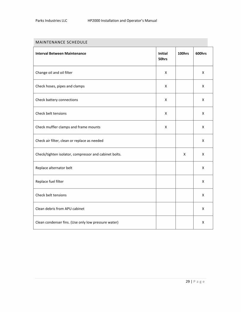
MAINTENANCE SCHEDULE
Interval Between Maintenance Initial
50hrs
100hrs 600hrs
Change oil and oil filter X X
Check hoses, pipes and clamps X X
Check battery connections X X
Check belt tensions X X
Check muffler clamps and frame mounts X X
Check air filter, clean or replace as needed X
Check/tighten isolator, compressor and cabinet bolts. X X
Replace alternator belt X
Replace fuel filter X
Check belt tensions X
Clean debris from APU cabinet X
Clean condenser fins. (Use only low pressure water) X
Parks Industries LLC HP2000 Installation and Operator’s Manual
30 | P a g e
A/C SYSTEM MAINTENANCE
It is recommended that you check your A/C system occasionally. The system holds 1.85 lbs of R-134a
refrigerant. If your APU has lost refrigerant, it has also lost oil. Only use pag-46 oil when servicing this unit.
It is a good idea to perform regular inspection of both coils.
Recommended operating pressures
A/C mode:
Low side = 20-21psi
High side = 225-270
Heat mode:
Low side = 30-31
High = 250-275

Parks Industries LLC HP2000 Installation and Operator’s Manual
31 | P a g e
OWNER’S RESPONSIBILITY
For the most up to date warranty procedure information, please see the HP2000 policy and
procedures information. This is available at any time from our website: www.hp2000apu.com
1. As the engine owner, you are responsible for the performance of the required maintenance
listed in your Owner’s Manual. We require that you retain the original purchase documentation
and all receipts covering maintenance on your engine.
2. Please be aware that we may deny warranty coverage if your engine or a part has failed due to
neglect, abuse, improper maintenance, improper installation, and or unapproved modifications.
3. As the owner, you are responsible for presenting your APU to an authorized service facility as
soon as a problem occurs. The warranty repairs should be completed in a reasonable amount of
time and following the SRT Guide (Suggested Repair Time).
4. Keep all maintenance records, dates, receipts, and parts used for all warranty claims. You may be
asked to provide all maintenance records and parts used for the warranty to be effective.
5. Inspecting your equipment daily will help keep your APU working for a long time. Daily
inspections should include items such as: belts, hoses, oil, bolts, mounts, etc. Dirt and debris in
the evaporator or condenser coil will cause unsatisfactory heating and cooling. Please keep these
cleaned at all times.
6. WHEN FILING A WARRANTY CLAIM OR ORDERING PARTS, YOU MUST HAVE THE FOLLOWING:
a. SERIAL NUMBER AND HOURS ON APU
b. PART NUMBER AND PART DESCRIPTION
Parks Industries LLC HP2000 Installation and Operator’s Manual
32 | P a g e
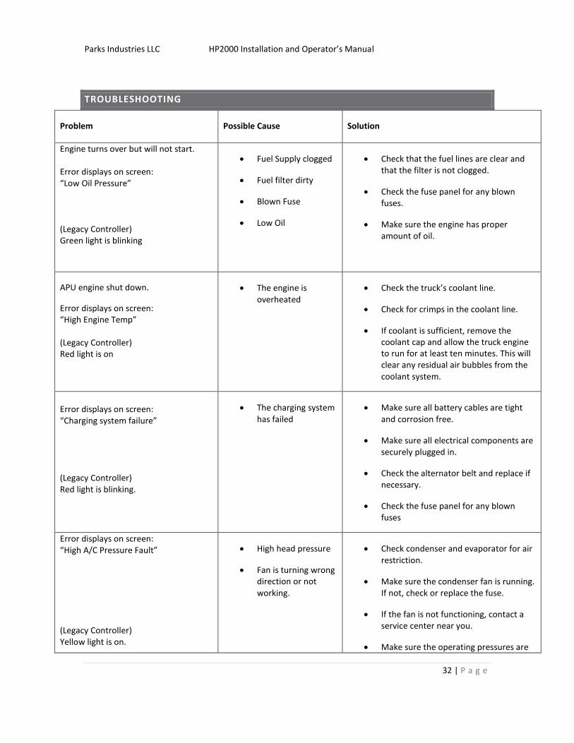
TROUBLESHOOTING
Problem Possible Cause Solution
Engine turns over but will not start. Error displays on screen: “Low Oil Pressure” (Legacy Controller) Green light is blinking
Fuel Supply clogged
Fuel filter dirty
Blown Fuse
Low Oil
Check that the fuel lines are clear and that the filter is not clogged.
Check the fuse panel for any blown fuses.
Make sure the engine has proper amount of oil.
APU engine shut down.
Error displays on screen: “High Engine Temp” (Legacy Controller) Red light is on
The engine is overheated
Check the truck’s coolant line.
Check for crimps in the coolant line.
If coolant is sufficient, remove the coolant cap and allow the truck engine to run for at least ten minutes. This will clear any residual air bubbles from the coolant system.
Error displays on screen: “Charging system failure” (Legacy Controller) Red light is blinking.
The charging system has failed
Make sure all battery cables are tight and corrosion free.
Make sure all electrical components are securely plugged in.
Check the alternator belt and replace if necessary.
Check the fuse panel for any blown fuses
Error displays on screen: “High A/C Pressure Fault” (Legacy Controller) Yellow light is on.
High head pressure
Fan is turning wrong direction or not working.
Check condenser and evaporator for air restriction.
Make sure the condenser fan is running. If not, check or replace the fuse.
If the fan is not functioning, contact a service center near you.
Make sure the operating pressures are
Parks Industries LLC HP2000 Installation and Operator’s Manual
33 | P a g e
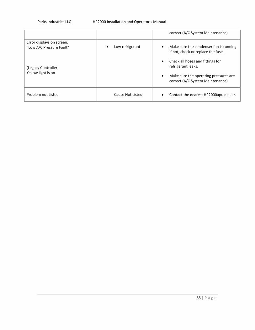
correct (A/C System Maintenance).
Error displays on screen: “Low A/C Pressure Fault” (Legacy Controller) Yellow light is on.
Low refrigerant Make sure the condenser fan is running. If not, check or replace the fuse.
Check all hoses and fittings for refrigerant leaks.
Make sure the operating pressures are correct (A/C System Maintenance).
Problem not Listed Cause Not Listed Contact the nearest HP2000apu dealer.

Parks Industries LLC HP2000 Installation and Operator’s Manual
34 | P a g e
WARRANTY PROCEDURE
Refer to dealer policy and procedures manual for warranty details.
Parks Industries LLC HP2000 Installation and Operator’s Manual
35 | P a g e
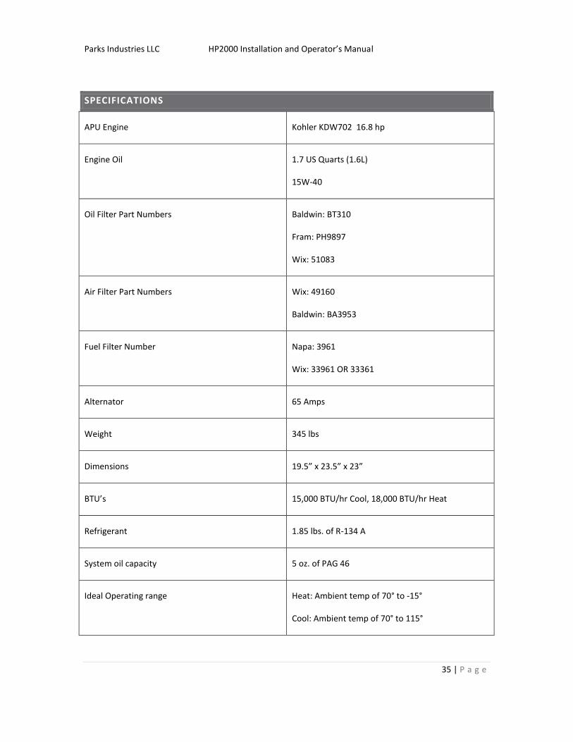
SPECIFICATIONS
APU Engine Kohler KDW702 16.8 hp
Engine Oil 1.7 US Quarts (1.6L)
15W-40
Oil Filter Part Numbers Baldwin: BT310
Fram: PH9897
Wix: 51083
Air Filter Part Numbers Wix: 49160
Baldwin: BA3953
Fuel Filter Number Napa: 3961
Wix: 33961 OR 33361
Alternator 65 Amps
Weight 345 lbs
Dimensions 19.5” x 23.5” x 23”
BTU’s 15,000 BTU/hr Cool, 18,000 BTU/hr Heat
Refrigerant 1.85 lbs. of R-134 A
System oil capacity 5 oz. of PAG 46
Ideal Operating range Heat: Ambient temp of 70° to -15°
Cool: Ambient temp of 70° to 115°

Parks Industries LLC HP2000 Installation and Operator’s Manual
36 | P a g e


