21
INSTALLATION AND SERVICE INSTRUCTION SD39GND-1 Rev: 2 January 1998 GROUNDING PRACTICES MOORE PRODUCTS CO., Spring House, PA 19477-0900 An ISO 9001 registered company
INSTALLATION AND SERVICE INSTRUCTION
SD39GND-1Rev: 2January 1998
GROUNDING PRACTICES
MOORE PRODUCTS CO., Spring House, PA 19477-0900An ISO 9001 registered company

SD39GND-1 CONTENTS
January 1998 i
TABLE OF CONTENTS
SECTION AND TITLE PAGE
1.0 INTRODUCTION . . . . . . . . . . . . . . . . . . . . . . . . . . . . . . . . . . . . . . . . . . . . . . . . . . . . . . . . . . . . . . 1-11.1 GROUNDING DEFINITION, CONTEXT, AND CLARIFICATION . . . . . . . . . . . . . . . . . . . . 1-11.2 DEFINITION OF ASSOCIATED TERMS . . . . . . . . . . . . . . . . . . . . . . . . . . . . . . . . . . . . . . . . 1-41.3 ACRONYMS AND ABBREVIATIONS . . . . . . . . . . . . . . . . . . . . . . . . . . . . . . . . . . . . . . . . . . 1-51.4 RELATED LITERATURE . . . . . . . . . . . . . . . . . . . . . . . . . . . . . . . . . . . . . . . . . . . . . . . . . . . . . 1-6
2.0 GROUNDING . . . . . . . . . . . . . . . . . . . . . . . . . . . . . . . . . . . . . . . . . . . . . . . . . . . . . . . . . . . . . . . . . 2-12.1 EQUIPMENT GROUNDING . . . . . . . . . . . . . . . . . . . . . . . . . . . . . . . . . . . . . . . . . . . . . . . . . . 2-1
2.1.1 MODULPAC Enclosure Grounding . . . . . . . . . . . . . . . . . . . . . . . . . . . . . . . . . . . . . . . . . 2-32.1.1.1 Enclosures with an External AC Power Feed . . . . . . . . . . . . . . . . . . . . . . . . . . . . . 2-32.1.1.2 Enclosures without an External AC Power Feed . . . . . . . . . . . . . . . . . . . . . . . . . . . 2-62.1.1.3 Clusters of Enclosures . . . . . . . . . . . . . . . . . . . . . . . . . . . . . . . . . . . . . . . . . . . . . . . 2-62.1.1.4 Isolated Enclosure . . . . . . . . . . . . . . . . . . . . . . . . . . . . . . . . . . . . . . . . . . . . . . . . . . 2-82.1.1.5 Enclosure Prepower Checkout . . . . . . . . . . . . . . . . . . . . . . . . . . . . . . . . . . . . . . . . . 2-8
2.1.2 MODULRAC Grounding . . . . . . . . . . . . . . . . . . . . . . . . . . . . . . . . . . . . . . . . . . . . . . . . . 2-82.1.3 POWERAC and Power Supply Module (PSM) . . . . . . . . . . . . . . . . . . . . . . . . . . . . . . . 2-10
2.1.3.1 Power Supply Module (PSM) Ground Requirements . . . . . . . . . . . . . . . . . . . . . . 2-102.1.3.2 POWERAC Ground Requirements . . . . . . . . . . . . . . . . . . . . . . . . . . . . . . . . . . . 2-10
2.1.4 Power Distribution Assembly Ground Requirements . . . . . . . . . . . . . . . . . . . . . . . . . . . 2-112.1.5 Uninterruptable Power Supply and Isolation Transformer Installations . . . . . . . . . . . . . 2-112.1.6 Intrinsically Safe Installations . . . . . . . . . . . . . . . . . . . . . . . . . . . . . . . . . . . . . . . . . . . . . 2-11
LIST OF FIGURES
FIGURE AND TITLE PAGE
FIGURE 1-1 Power Conductors Incorporating the Word “Ground” as Descriptor . . . . . . . . . . . . . . . . . 1-2FIGURE 1-2 Isolated Ground . . . . . . . . . . . . . . . . . . . . . . . . . . . . . . . . . . . . . . . . . . . . . . . . . . . . . . . . . 1-3
FIGURE 2-1 Enclosure and Overview Ground Map . . . . . . . . . . . . . . . . . . . . . . . . . . . . . . . . . . . . . . . . 2-4FIGURE 2-2 Enclosures with/without Power Feeder Grounding Requirements . . . . . . . . . . . . . . . . . . . 2-5FIGURE 2-3 I/O Transition Boards Ground Map . . . . . . . . . . . . . . . . . . . . . . . . . . . . . . . . . . . . . . . . . . 2-7FIGURE 2-4 Isolated Enclosure Grounding . . . . . . . . . . . . . . . . . . . . . . . . . . . . . . . . . . . . . . . . . . . . . . 2-9FIGURE 2-5 Power Supply and Module Ground Map . . . . . . . . . . . . . . . . . . . . . . . . . . . . . . . . . . . . . 2-12
CONTENTS SD39GND-1
January 1998ii
SIGNIFICANT CHANGES FOR REVISION 2
The significant changes for revision 2 include the provision of a more detailed identifier for the descriptor“lockwasher,” now specified as “external tooth lockwasher” or “tooth lockwasher,” on Figures 2-1, 2-2, 2-3, and 2-5. In the equipment grounding for an enclosure with an external AC power feed (section2.1.1.1), an exception is provided for the 230 Vac version Power Distribution Assembly (PDA). Additionally, some minor text and graphics clarifications were made in section 1, specifically section 1.2and Figure 1-1. These changes are marked by change bars located in the margins of graphics pagesadjacent to the figure number/title of affected graphics or in the margins of text pages adjacent to thechanged matter.
Moore Products Co. assumes no liability for errors or omissions in this document or for the application and use of information included in thisdocument. The information herein is subject to change without notice.
The Moore logo, ProcessSuite, APACS, QUADLOG, the APACS logo, the QUADLOG logo, and 4-mation are trademarks of Moore Products Co.All other trademarks are the property of the respective owners.
© Copyright1998 Moore Products Co. All rights reserved
#
SD39GND-1 INTRODUCTION
January 1998 1-1
1.0 INTRODUCTION
The document provides guidelines for electrical grounding and shielding of electronic process controlmodules and associated equipment. This document, which is applicable to equipment associated with theAdvanced Process Automation and Control System (APACS) and the QUADLOG safety PLC, isorganized as follows:
• Section 1, Introduction - Clarifies the meaning of the word “ground” and defines associated terms andacronyms.
• Section 2, Grounding - Provides the grounding requirements for APACS/QUADLOG enclosures andpower-related equipment in reference to applicable sections of the National Electrical Code (NEC)Handbook.
1.1 GROUNDING DEFINITION, CONTEXT, AND CLARIFICATION
Grounding refers to the techniques used to provide protection from electrical shock and lightning, and to those used to control noise and electromagnetic radiation. The subject of grounding is often misconceived,its issues involving the entire electromagnetic spectrum. Differing viewpoints on the meaning of the word“ground” held by the power industry and by electronic engineers are given as follows:
C The power industry uses the word “ground” in a very specific context: a grounded conductor is onethat makes an earth connection. Specifically, the grounded conductor in a power system is a current-carrying conductor that is earthed at the service entrance. In a three-phase system, “ground” is also theneutral conductor.
C To an electronics engineer, “ground” can mean any of the following:- A chassis connection- A ground plane connection- Connection to a safety wire- Connection to power supply common which may or may not be earthed (floating)
Numerous legal ramifications are attached to the procedures used by the power industry, which is heldaccountable to the National Electrical Code (NEC). The NEC descriptor for each key conductor uses theroot “ground” in a variety of ways (see Figure 1-1). Note that the term “safety ground,” commonly usedin electrical literature, is not used by the NEC, which prefers the equivalent descriptor “equipmentgrounding conductor.” Both terms are used in text and illustrations in this document.

INTRODUCTION SD39GND-1
January 19981-2
FIGURE 1-1 Power Conductors Incorporating the Word “Ground” as Descriptor*
SD39GND-1 INTRODUCTION
January 1998 1-3
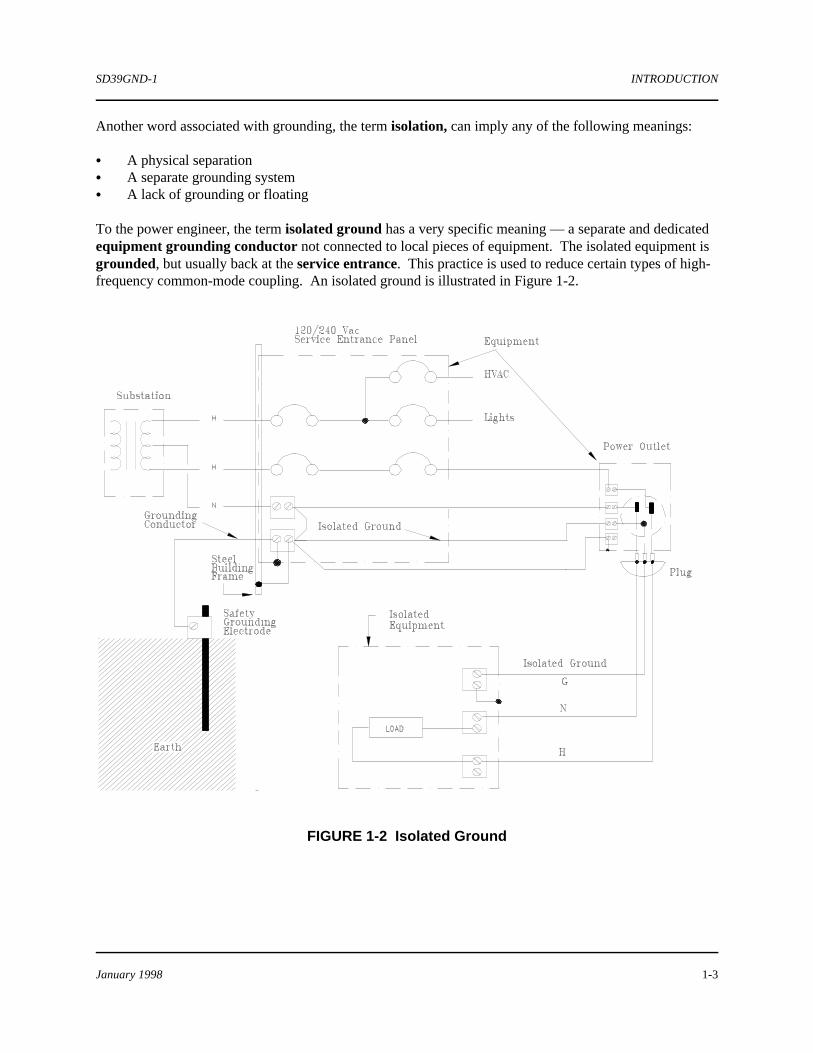
Another word associated with grounding, the term isolation, can imply any of the following meanings:
C A physical separationC A separate grounding systemC A lack of grounding or floating
To the power engineer, the term isolated ground has a very specific meaning — a separate and dedicatedequipment grounding conductor not connected to local pieces of equipment. The isolated equipment isgrounded, but usually back at the service entrance. This practice is used to reduce certain types of high-frequency common-mode coupling. An isolated ground is illustrated in Figure 1-2.
FIGURE 1-2 Isolated Ground
INTRODUCTION SD39GND-1
January 19981-4
1.2 DEFINITION OF ASSOCIATED TERMS
The following terms are defined to assist you in understanding their relationship to the subject ofgrounding and their use in this document. Please read them carefully before proceeding to section 2.0.
Building steel: Any electrically conductive structural member to which safety grounds may be connected.
Cluster: A group of APACS or QUADLOG MODULPAC enclosures (containing process controlequipment) that are electrically connected by gang mounting (bolted together) or by communications vianon-isolated MODULBUS or redundancy connections (cables).
Common mode voltage: A voltage that appears equally on both wires (of a pair) with respect to acommon reference, usually system common or safety ground.
Earth ground: A ground, created by rods suitably installed in the earth, whose primary purpose is toprovide a return path for the current induced by lightning strikes. A secondary purpose is to provide anearth reference for the power system for electrical safety.
Electromagnetic Interference (EMI): Any conducted or radiated electromagnetic disturbance thatimpairs the operation of electronic equipment. This covers the total frequency spectrum.
Electrostatic Discharge (ESD): Electrical discharge due to a potential (voltage) buildup.*
Ground: A conducting path through which an electronic circuit is connected to earth or another commonreference. Ground is a term to be avoided, as it does not define intended use or purpose. Use insteadsystem common, signal common, building steel, safety ground, or earth ground.
Ground loop: An undesired current flowing in a signal common, usually because of multiple connectionsto building steel.
Ground resistance: In the case of an earth ground, it is the resistance in ohms between the earth groundpoint and a theoretically perfect conducting sphere of infinite radius. There are a number of practicalmethods for measuring this [as described in IEEE Standard 142-1982 (5)]. In all other cases, it is theresistance measured between two specified points.
IOBUS: The APACS/QUADLOG redundant communication bus dedicated to I/O communication. Provides a control module, or any other module supporting an IOBUS, with dedicated, secure access to I/Opoints, which are terminated at I/O modules and fully isolated on a per module basis.
I/O Module: Generic name for an APACS/QUADLOG module that acts as an interface between fieldsignals and control modules.
Isolated I/O - An input or output circuit where the signal terminals are electrically isolated from thatcircuit’s power and safety ground terminals. The input or output signal is often coupled using magnetic orphotoelectric techniques. Isolation prevents undesired current flow through the signal wires to safetyground.

SD39GND-1 INTRODUCTION
January 1998 1-5
Linear ground path: A grounding path which can be traced from an equipment connection to a singlecommon point, without forming any loops.
MODULBUS (M-BUS): The APACS/QUADLOG redundant communication bus dedicated tocoordinating module-to-module communications. Used by control, communication, and computermodules to exchange process and system information. *
MODULPAC: Generic name of an APACS/QUADLOG industrial enclosure.
MODULRAC: Standard card rack for the APACS/QUADLOG system. Includes card cage, backplane,and mounting panel. The card cage supports insertion of up to ten APACS/QUADLOG plug-in modules. The backplane provides the connections for the communication and power buses. The mounting panelsupports transition boards.
Normal mode voltage: A voltage that appears across a pair of signal wires and, thus, is part of the signal.
Power Distribution Assembly (PDA): The APACS/QUADLOG DIN rail-mounted assembly for ACpower distribution within an enclosure. Contains integrated surge suppression.
Safety ground (equipment ground): A ground system to which all metallic equipment is connected so asto provide safety in the event of a power line fault. Requirements are specified by the NEC (Article 250,Grounding).
Shield: A metallic enclosure used to minimize the coupling of EMI into the circuit that it surrounds. Inthis sense, equipment cabinets and other metallic housings, conduit, and the braid or foil wrapped aroundsignal wires are all shields. Except in RF applications, shields should never carry signal currents orreference signal voltages. Ferrous shields are used for low frequency and static magnetic shieldingrequirements.
Signal common: A reference point for a particular signal, typically on an I/O channel. It is generally at ornear the same potential as the system common.
System common: The single point to which all system commons, within a cluster, are referenced(connected). Typically, this point is located at (or connected to) the local power distribution panel safetyground, which is also power line neutral when an isolation transformer is used.

INTRODUCTION SD39GND-1
January 19981-6
1.3 ACRONYMS AND ABBREVIATIONS
The following acronyms and abbreviations are provided to assist you in their use in the followingdiscussion of grounding. Please familiarize yourself with them before proceeding to section 2.0.
APACS: Advanced Process Automation and Control SystemESD: Electrostatic DischargeEMI: Electromagnetic InterferenceI/O: Input/OutputIOBUS APACS Input/Output BusM-BUS: APACS/QUADLOG MODULBUSM-NET: APACS/QUADLOG MODULNET
1.4 RELATED LITERATURE
The following literature should be available as references when grounding an APACS or a QUADLOGsystem.
• Power Distribution Assembly (PDA) Installation and Service Instruction (SD39PDA-1)• MODULRAC and Local Termination Panel Installation and Service Instruction (SD39MODULRAC-1)• Power Supply Rack (POWERAC) Installation and Service Instruction (SD39PSR-1)• Power Supply Module (PSM) Installation and Service Instruction (SD39PSM-1)• MODULPAC 1000 Industrial Enclosure Installation and Service Instruction (SD39MODULPAC-1)• MODULPAC 2000 Industrial Enclosure Installation and Service Instruction (SD39MODULPAC-2)• National Electrical Code (NEC) Handbook, 1998 Edition
#
SD39GND-1 GROUNDING
January 1998 2-1
2.0 GROUNDING
A specific design goal of APACS and of QUADLOG was to minimize the need for an extraordinary andelaborate grounding system. The grounding design principles are:
• Input/output channels are galvanically isolated from module communications, control modules, andpower feeds.
• Non-galvanically isolated APACS/QUADLOG racks constitute a cluster for which interconnections areprovided, such as MODULBUS (M-BUS) and redundancy connections.
• Externally extendible communications are galvanically isolated from clusters.• Shield connections are segregated from the signals and signal common via independent tie points.• Power feed returns and module commons are segregated and have independent paths to minimize the
effects of power supply noise.
Figures 2-1 to 2-5 provide ground maps of APACS/QUADLOG enclosures and power-related equipment. The grounding requirements of specific system elements are discussed in the following sections.
2.1 EQUIPMENT GROUNDING
The purpose of equipment grounding is to ensure that the equipment does not develop a hazardouspotential that could cause personal injury.
IMPORTANT
Equipment installation must adhere to the National Electric Code (NEC) and allother applicable codes under the jurisdiction of local regulatory agencies.
The following are some of the National Electric Code (NEC) specifications pertaining to equipmentgrounding:
• Article 250 GROUNDINGPart E - Equipment GroundingSection 250-42 - Equipment Fastened in Place or Connected by Permanent Wiring Methods
(1) Exposed noncurrent carrying metal parts of fixed equipment likely to become energized shall begrounded.
• Article 250 GROUNDINGPart F - Methods of GroundingSection 250-51 - Effective Grounding Path
The path to ground from circuits, equipment, and metal enclosures for conductors shall:(1) be permanent and electrically continuous(2) have capacity to conduct safely any fault current likely to be imposed on it(3) have sufficiently low impedance to limit the voltage to ground and to facilitate the operation of
circuit-protective devices
GROUNDING SD39GND-1
January 19982-2
The earth shall not be used as the sole equipment grounding conductor.
• Article 250 GROUNDINGPart F - Methods of GroundingSection 250-57-Equipment Fastened in Place or Connected by Permanent Wiring Methods-Grounding
Noncurrent-carrying parts of equipment, raceways, and other enclosures, where required to be grounded,shall be grounded by one of the following methods:
(a) Section 250-91(b)-Equipment Grounding Conductor Types. The equipment groundingconductor run with or enclosing the circuit conductors shall be one or more or a combination of thefollowing: (1) Copper or other corrosion-resistant conductor. The conductor shall be solid or stranded;
insulated, covered, or bare; and in the form of a wire or busbar of any shape.(2) Rigid metal conduit, intermediate metal conduit, electrical metallic tubing, flexible metal conduit
where the conduit and fittings are listed for grounding , and armor-type AC cable.
(b) With Circuit Conductors. By an equipment grounding conductor contained within the sameraceway, cable, or cord or otherwise run with the circuit conductors. Bare, covered, or insulatedequipment grounding conductors shall be permitted. Individually covered or insulated equipmentgrounding conductors shall have a continuous outer finish that is either green, or green with one ormore yellow stripes. Sheet metal screws shall not be used to connect an equipment groundingconductor to equipment.
• Article 250 GROUNDINGPart F - Methods of GroundingSection 250-58 - Equipment Considered Effectively Grounded
Under the conditions specified in (a), the noncurrent-carrying metal parts of the equipment shall beconsidered to be effectively grounded.
(a) Equipment Secured to Grounded Metal Supports. Electrical equipment secured to and in
electrical contact with a metal rack or structure provided for its support and grounded by one of themeans indicated in section 250-57. The structural metal frame of a building shall not be used asthe required equipment grounding conductor for ac equipment.
• Article 250 GROUNDINGPart G - BondingSection 250-75 - Bonding Other Enclosures
The Code states that metal raceways, enclosures, and other metal noncurrent-carrying parts that are toserve as grounding conductors with or without the use of supplementary equipment groundingconductors shall be effectively bonded to ensure electrical continuity and the capacity to conduct safelyany fault current likely to be imposed on them.
SD39GND-1 GROUNDING
January 1998 2-3
Exception: where required for the reduction of electrical noise (electromagnetic interference) on thegrounding circuit, an equipment enclosure supplied by a branch circuit shall be permitted to be isolatedfrom a raceway containing circuits supplying only that equipment by one or more listed nonmetallicraceway fittings located at the point of attachment of the raceway to the equipment enclosure. The metalraceway shall be supplemented by an internal insulated equipment grounding conductor installed inaccordance with Section 250-74, Exception No. 4, to ground the equipment enclosure. The use of anisolated grounding conductor does not relieve the requirement for grounding the raceway system. Theexception permits the isolated (and insulated) grounding conductor to pass through the local powerdistribution panel without a connection.
2.1.1 MODULPAC Enclosure Grounding
At installation, an enclosure or cluster of enclosures requires a connection to safety ground in a nearbybreaker panel. The following are standard enclosures:
• MODULPAC 1000 - Refer to the MODULPAC 1000 Industrial Enclosure Installation and ServiceInstruction (SD39MODULPAC-1) for installation procedures.
• MODULPAC 2000 - Refer to the MODULPAC 2000 Industrial Enclosure Installation and ServiceInstruction (SD39MODULPAC-2) for installation procedures.
2.1.1.1 Enclosures with an External AC Power Feed
AC power feed conductors that are brought into an enclosure from a nearby breaker panel are connected toa device provided for enclosure power. The device is a Power Distribution Assembly (PDA) and isavailable in 115 Vac and 230 Vac versions. Each version provides power-disconnect capability, over-current protection, surge suppression, and power distribution. The PDA design does not fuse the second *leg of the power feeds in the 230 Vac version. The PDA assemblies are intended for use with a single- *phase power feed with a ground referenced neutral. The provision for the higher voltage PDA is for *international system installations that use single-phase 230/240 Vac. The recommended power feed *conductor size for both versions is #10 AWG (30 amp fuse). Installation details and specifications are *provided in the Power Distribution Assembly (PDA) Installation and Service Instruction (SD39PDA-1).
The PDA is connected to the enclosure frame via monitoring hardware (as shown in Figure 2-1). Whenthe power feed conductors are brought into the enclosure, the feeder ground conductor (green or green withyellow stripes) is connected to the safety ground terminal block of the PDA. This forms an electrical bondwith the enclosure frame, as the safety ground terminal block is grounded to the frame via the PDAmounting plate assembly. Thus, the feeder ground conductor provides a safety ground for the enclosure,as required by Section 250-42 of the NEC. As specified by NEC Section 250-51 (and shown in Figure 2-2), the equipment grounding conductor (safety ground) must be continuous back to the service entrancepanel and connected to system ground. Additional safety ground connections or metallic conduit installedby the user will not cause problems.

MODULPAC 1000/2000 Metal Enclosure
M8 screw/external toothlockwasher(8 places)
Power Distribution Assembly (PDA)
10 AWG
M5 thread cutting screwM5 screw/external
10 AWG customer installed safety ground wireto local breaker panel
Process InterconnectI/O Cable connectionsfrom Marshalled TerminationAssembly
Shielded cablesto MBUS (baseboard)and ICM/NIM TransitionBoards
See Figure 2-5for more detail
See Figure 2-3for more detail
Phoenix UISLKG16
Shield Wire
tooth lockwasher
GROUNDING SD39GND-1
January 19982-4
FIGURE 2-1 Enclosure and Overview Ground Map*

SD39GND-1 GROUNDING
January 1998 2-5
FIGURE 2-2 Enclosures with/without Power Feeder Grounding Requirements *

GROUNDING SD39GND-1
January 19982-6
2.1.1.2 Enclosures without an External AC Power Feed
An enclosure or cluster of enclosures without an AC power feed requires connection to safety ground atinstallation to satisfy the following conditions:
• The APACS and the QUADLOG designs provide shield screw terminals for field I/O wiring. The shieldterminals on local termination strips mounted to a MODULRAC are effectively grounded to theMODULRAC’s mounting plate via mounting screws.
The shield terminal screws on a marshalled termination assembly in a remotely located enclosure aregrounded to the MODULRAC’s mounting plate via a grounding conductor in the I/O Interconnect CableAssembly. At the MOUDULRAC end of the cable, the ground conductor exits the cable jacket as a wireattached to a ring terminal. The ring terminal is placed under the head of the cable connector’s captivemounting screw. When the cable connector is screw-mounted to the MODULRAC plate, the shieldconductor is effectively grounded (see Figure 2-3).
Thus, grounding an enclosure containing a MODULRAC provides the ground for the shields.
• To ensure proper operation of current and safety protection devices in the case of wiring errors (ACmistakenly brought into the cabinet). Certain APACS/QUADLOG modules interface to AC inputs andoutputs. Units which have these types of I/O in an enclosure are to be safety-grounded.
• Dissipation of any potential buildup which could compromise personal safety.
Each of the structural frame members that join together at each corner of the frame in a MODULPACcabinet contain several threaded holes that accept M8 screws. These holes can be used in conjunction withsuitable user-supplied mounting hardware and attachment hardware (ring terminal, grounding stud, etc.) toconnect a #14 AWG grounding conductor (or larger based on possible current into cabinet) in conduit,from the frame to safety ground in a nearby breaker panel. The conductor must meet the color coderequirements of NEC Section 250-57(b). A #4 AWG conductor can be used without a conduit.
Alternatively, if a MODULPAC that is already safety-grounded is nearby, the safety ground conductorfrom the ungrounded MODULPAC can be connected to the safety ground bus in that enclosure.
2.1.1.3 Clusters of Enclosures
When several MODULPACs are bolted together to form a cluster of enclosures, only an end enclosurerequires connection to safety ground, even when each enclosure has a power feeder. The size of theconductor shall match the total power capacity of all power feeds. This connection is still required evenwhen all of the enclosures have no AC power feeder.

SD39GND-1 GROUNDING
January 1998 2-7
FIGURE 2-3 I/O Transition Boards Ground Map *

GROUNDING SD39GND-1
January 19982-8
2.1.1.4 Isolated Enclosure
Under circumstances where it may be necessary to reduce electromagnetic interference, NEC section 250-75 permits the enclosure to be isolated and grounded by an insulated grounding conductor taken directlyback to the service entrance panel and terminated to system ground. Figures 1-2 and 2-4 illustrate isolatedgrounding.
2.1.1.5 Enclosure Prepower Checkout
After the power feed(s) have been installed and connected, check the power system as follows:
1. At the local breaker panel, remove AC operating power (feeder breaker off) to the enclosure.
2. With a multimeter, check for a maximum resistance of 0.5 ohm between the frame of the enclosure andthe nearest grounded pipe or conduit. A high reading usually means that the enclosure is notconnected to safety ground.
3. At the breaker panel, set the feeder breaker to on. At the Power Distribution Assembly (PDA) in theenclosure, set the power disconnect switch to off. With the multimeter, check for proper AC voltage atthe input to the PDA.
4. On a 120 Vac system, use the multimeter to check the potential difference between the neutralconductor input to the PDA and the enclosure frame. The potential should be 0.5 Vac or less. Ahigher potential can mean that either the neutral conductor at the service entrance panel is notconnected to safety ground, or the enclosure frame is not connected to safety ground.
2.1.2 MODULRAC Grounding
MODULRAC is a10-slot rack that provides for mounting APACS and QUADLOG modules. MODULRAC is classified as panel-mounted equipment and is typically installed in a MODULPACenclosure. As shown in Figure 2-1, the MODULRAC mounting plate is effectively grounded to theenclosure frame via mounting hardware. An optional (but highly recommended) safety ground conductorcan be connected from the plate’s ground stud (bottom right corner) to the safety ground terminal block onthe PDA.
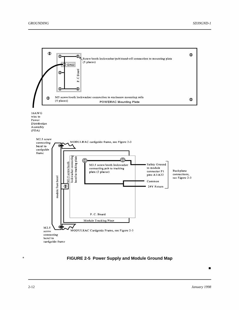
As shown in Figure 2-3, the MODULRAC incorporates two references which are defined as module“common” and “earth ground” (safety ground). A third reference is the 24V return (power supply returnpath). The design of the system adheres to the cluster/linear grounding philosophy discussed previously. The implementation of the cluster/continuous ground is achieved by having each module connect itslocally derived “common” (negative side of each module’s power supply) to a “module common” sharedby all modules (see Figures 2-3 and 2-5). “Module common” is tied back to “earth ground,” which iselectrically connected (effectively grounded) to the enclosure frame. If the enclosure incorporates a PDA,then the grounding is complete, as the PDA provides the enclosure safety ground connection. If theenclosure does not have a PDA or other user-supplied grounding-type connection, then the enclosure canbe grounded as specified in section 2.1.1.2.

SD39GND-1 GROUNDING
January 1998 2-9
FIGURE 2-4 Isolated Enclosure Grounding
GROUNDING SD39GND-1
January 19982-10
2.1.3 POWERAC and Power Supply Module (PSM)
The module family for APACS and for QUADLOG is powered from a 24 Vdc source. Two AC-to-DCconverters are available to provide this 24 Vdc operating power:
• POWERAC - Refer to the POWERAC Installation and Service Instruction (SD39POWERAC-1) forinstallation procedures.
• Power Supply Module (PSM) - Refer to the Power Supply Module Installation and Service Instruction(SD39PSM-1) for installation procedures.
Cables from these devices connect to the backplane of the MODULRAC, which distributes the 24 Vdc tothe installed modules via three independent paths.
2.1.3.1 Power Supply Module (PSM) Ground Requirements
A system powered by a Power Supply Module (PSM) receives 115/230 Vac operating power by either ofthe following paths:
• Via the path local breaker panel-to-PDA-to-PSM• Via the path local breaker panel-to-PSM
The connection to a terminal on the PSM local termination strip marked GND (see Figure 2-3) is bondedto the MODULRAC’s metal mounting plate via the strip board’s pc tracks and mounting hardware. Thiseffectively grounds the GND terminal to the enclosure frame. The integrity of the connection can be testedby measuring the resistance between the GND terminal and the ground stud located at the lower rightcorner of the MODULRAC’s mounting plate. If the resistance is greater than 0.2 ohm, check that the PSMtermination strip’s mounting screw holes are free of contaminants and the screws firmly tightened. TheGND connection is used to connect the PSM termination strip to safety ground at the PDA or local breakerpanel. The connecting conductor should be at least the same size (AWG or circular MIL) as the powerfeed conductor. The power conductor size is a function of the type of cable used (insulation ratings) andthe ampacity of the load.
Refer to the Power Supply Module (PSM) Installation and Service Instruction (SD39PSM-1) for currentdraw specifications.
2.1.3.2 POWERAC Ground Requirements
A system powered by a POWERAC receives 115/230 Vac operating power by either of the followingpaths:
• Via the path local breaker panel-to-PDA-to-POWERAC• Via the path local breaker panel-to-POWERAC
SD39GND-1 GROUNDING
January 1998 2-11
The connection to a terminal on the POWERAC transition board marked GND (see Figure 2-5) is bondedto the POWERAC’s metal mounting plate via the board’s pc tracks and mounting hardware. Thiseffectively grounds the GND terminal to the enclosure frame. The GND connection is used to connect thePOWERAC to safety ground at the PDA or local breaker panel. The connecting conductor should be atleast the same size (AWG or circular MIL) as the power feed conductor. The power conductor size is afunction of the type of cable used (insulation ratings) and the ampacity of the load. Refer to thePOWERAC Installation and Service Instruction (SD39POWERAC-1) for current draw specifications.
A ground stud at the bottom right corner of the POWERAC metal panel is available for connection of anoptional safety ground conductor (#14 AWG).
2.1.4 Power Distribution Assembly Ground Requirements
The device provided for enclosure power is a Power Distribution Assembly (PDA). The PDA is availablein 115 Vac and 230 Vac designs. Each incorporates power-disconnect capability, over-current protection,surge suppression, and power distribution. The 115 Vac PDA incorporates a 30 ampere fuse, whereas the230 Vac PDA is fused at 15 amperes. The recommended power wiring (G, N, H) to either version is #10AWG (10380 circular MIL area), with the color coding per applicable codes. The PDA connects to theenclosure via monitoring hardware on the frame. This forms an electrical bond for enclosure grounding, asthe ground wire is tied to the PDA plate assembly.
The PDA includes surge suppression on the input power feeds. Power feeds are single-phase. The surgesuppressors serve to limit transients on the power lines. The suppressors are triggered by an increase involtage and, upon activation, shunt current to the ground conductor to limit the peak transient voltage. Theeffectiveness of the suppression device is directly related to the resistance of the grounding path to anactual earth ground or grounding grid. The resistance of this path should be less than 5 ohms to ensureeffective shunting of large currents associated with surges (e.g. lightning strikes). A resistance of 1.5 ohmsis typical due to the conductor size (#10 AWG or lower) and cable runs less than 1000 feet (304.8 meters). In systems comprised of multiple enclosures, the rules change very little when power feeds are added tosupply the system. The “5 ohms or less” suggestion is not a requirement of the equipment groundingconductor, as this conductor should be sized for personnel safety. Typically, this wire size is as large as thelargest current-carrying supply feeder to an enclosure and will ensure effective operation of power-interruptive devices such as breakers and fuses.
2.1.5 Uninterruptable Power Supply and Isolation Transformer Installations
Uninterruptable Power Supplies (UPS) or isolation transformers should be installed in accordance with themanufacturers’ recommendations and codes. The grounding requirements do not change, and groundingconnections should conform to this document.
2.1.6 Intrinsically Safe Installations
Intrinsically safe installations are not covered in this document, as they require system-specific installationguidelines. Refer to NEC articles 500 to 510.
GROUNDING SD39GND-1
January 19982-12
FIGURE 2-5 Power Supply and Module Ground Map*
#


