22
Installation Instruction BEECHCRAFT SUPER KING AIR 200 & 300 www.aveoengineering.com

Installation Instruction
BEECHCRAFT SUPER KING AIR 200 & 300 www.aveoengineering.com
BEECHCRAFT SUPER KING AIR 200 & 300 Installation Instructions AVE-MOD-032-INS
Issue 01
__________________________________________________________________________________ Aveo Engineering Group, s.r.o.
Drasov 202, 261 01 Drasov Czech Republic
Issue of form 01
Page 2 of 22
Part 0 Manual Administration 0.1 Table of Contents
PART 0 MANUAL ADMINISTRATION 2
0.1 TABLE OF CONTENTS 2
0.2 DOCUMENT APPROVAL 3
0.3 AMENDMENT RECORD PROCEDURE 4
0.4 AFFECTED PAGES PROCEDURE 4
PART 1 INSTALLATION INSTRUCTION 5
1.1 GENERAL 5
1.2 CONTINUED AIRWORTHINESS 5
1.3 DESCRIPTION 5
1.4 WING POSITION LIGHTS INSTALLATION 6
1.4.1 Wiring Change Position and Strobe Lights 9
1.5 REAR POSITION LIGHT INSTALLATION 14
1.6 ANTI-COLLISION LIGHTS INSTALLATION 16
1.7 TAXI AND LANDING LIGHTS INSTALLATION – NOSE GEAR 18
PART 2 COMPLIANCE DEMONSTRATION 21
BEECHCRAFT SUPER KING AIR 200 & 300 Installation Instructions AVE-MOD-032-INS
Issue 01
__________________________________________________________________________________ Aveo Engineering Group, s.r.o.
Drasov 202, 261 01 Drasov Czech Republic
Issue of form 01
Page 3 of 22
0.2 Document approval This document has been established in accordance with an alternative procedure to DOA approved under EASA AP429. This installation Instruction is applicable for the Beechcraft models 200, 200C, 200CT, 200T, 300 and 300LW.
Compiled by: 12. – Dec. - 2019 Petr Jaros
Engineer, Aveo Engineering Group, s.r.o.
Approved by: 12. – Dec. - 2019 Georg Hartl
Head of DO, Aveo Engineering Group, s.r.o.

BEECHCRAFT SUPER KING AIR 200 & 300 Installation Instructions AVE-MOD-032-INS
Issue 01
__________________________________________________________________________________ Aveo Engineering Group, s.r.o.
Drasov 202, 261 01 Drasov Czech Republic
Issue of form 01
Page 4 of 22
0.3 Amendment Record procedure The master copy of this document shall be kept electronically as a read only document under the control of Aveo Engineering Group, s.r.o. as Master Copy. ALL amendments to this manual will initiate a raise of Issue ALL raises of issue will be given a sequential Alphabetic Issue Ident sequentially from 01 to 99 in Table 01 - Issue No: Column– Initial Issue of Document will be “01” ALL Issues of this document will be approved by Head of DO
0.4 Affected Pages Procedure ALL pages affected by ANY raise of issue of this document will be listed in Table 01 - Affected Pages Column. The reason(s) for ALL raise of issue and description of change due to raise of issue will be provided for ALL raises of issue in Table 01 - Details Column. Changes from the previous issue are highlighted by YELLOW HIGHLIGHTING over new content. AND YELLOW HIGHLIGHTING AND CROSSING OUT of deleted content. Example (CROSSING OUT)
Issue No. Details Date Affected
Pages 01 Initial Issue ALL
Table 01: Document Amendment Record Table

BEECHCRAFT SUPER KING AIR 200 & 300 Installation Instructions AVE-MOD-032-INS
Issue 01
__________________________________________________________________________________ Aveo Engineering Group, s.r.o.
Drasov 202, 261 01 Drasov Czech Republic
Issue of form 01
Page 5 of 22
Part 1 Installation Instruction 1.1 General
This installation is to be performed in accordance to common practice as described in FAR AC 43.13-2B Chapter 4 and in FAR AC 43.13 1B Chapter 11 Section 15 (Bonding) as published by FAA. The installer is responsible to follow the installation instructions in the latest revision of:
• FAR AC 43.13-2B Chapter 4 • FAR AC 43.13 1B Chapter 11 Section 15 • AVE-WPS-64G-IM • AVE-PSPSYW-IM • AVE-RBXP-001-IM • AVE-N09PANSN-IM • AVE-H30-001-IM
All drawings applicable for this change are listed in the Drawing List:
• AVE-MOD-032-DL, issue 01
The following appliances carry an ETSO authorization:
• AVE-WPSR-64G & AVE-WPSG-64G – ETSOA 210.10053936
• AVE-RBXPR-001 – ETSOA 210.10055069
• AVE-PSPSYW-T01 – ETSOA 21O.10068603
The change is to be performed using the document AVE-MOD-032-MCS in the latest issue.
The aircraft modified according to this instruction may not be released back to service without the EASA design approval certificate being provided.
1.2 Continued Airworthiness The aircraft manuals remain fully valid. The inspection intervals and the procedures of the aircraft override the general statements in the component manuals as listed under §1.1.
For inspection of the new lights themselves follow the procedure defined in AVE-MOD-032-SUP-AMM supplied with this modification.
1.3 Description This modification is the replacement of position lights (type I, II & III), anti-collision lights, strobe lights, taxi lights and the landing lights by LED type lights. In general the lights are direct replacements and do not require any structural change on the A/C side. Only exemption may be additional attachment holes and installation of anchor nuts in the secondary bracket of the wingtip light installation. The changes in wiring are very minor and are described in this modification or are to be done according to referenced standard practice (e.g. change of connector).
BEECHCRAFT SUPER KING AIR 200 & 300 Installation Instructions AVE-MOD-032-INS
Issue 01
__________________________________________________________________________________ Aveo Engineering Group, s.r.o.
Drasov 202, 261 01 Drasov Czech Republic
Issue of form 01
Page 6 of 22
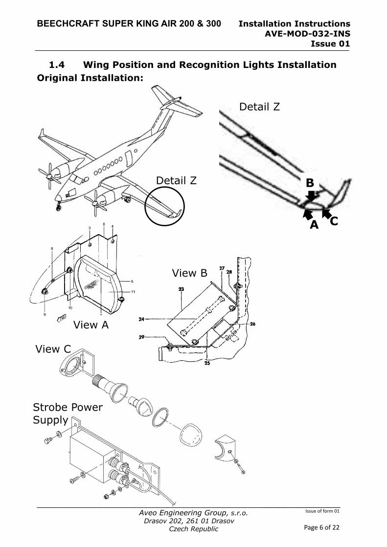
1.4 Wing Position and Recognition Lights Installation Original Installation:
View C
View A
B
A C
Detail Z
Detail Z
View B
Strobe Power Supply
BEECHCRAFT SUPER KING AIR 200 & 300 Installation Instructions AVE-MOD-032-INS
Issue 01
__________________________________________________________________________________ Aveo Engineering Group, s.r.o.
Drasov 202, 261 01 Drasov Czech Republic
Issue of form 01
Page 7 of 22
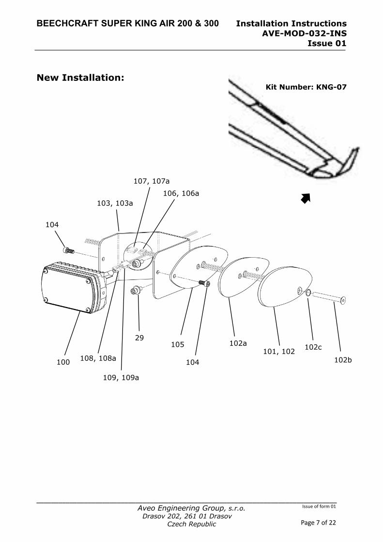
New Installation:
Kit Number: KNG-07
100
103, 103a
29
101, 102
104
104
106, 106a
105
107, 107a
109, 109a
108, 108a 102c
102b
102a
BEECHCRAFT SUPER KING AIR 200 & 300 Installation Instructions AVE-MOD-032-INS
Issue 01
__________________________________________________________________________________ Aveo Engineering Group, s.r.o.
Drasov 202, 261 01 Drasov Czech Republic
Issue of form 01
Page 8 of 22
Figure and Index Number
Part Number Description Parts Avail.
QTY. Per
assy.
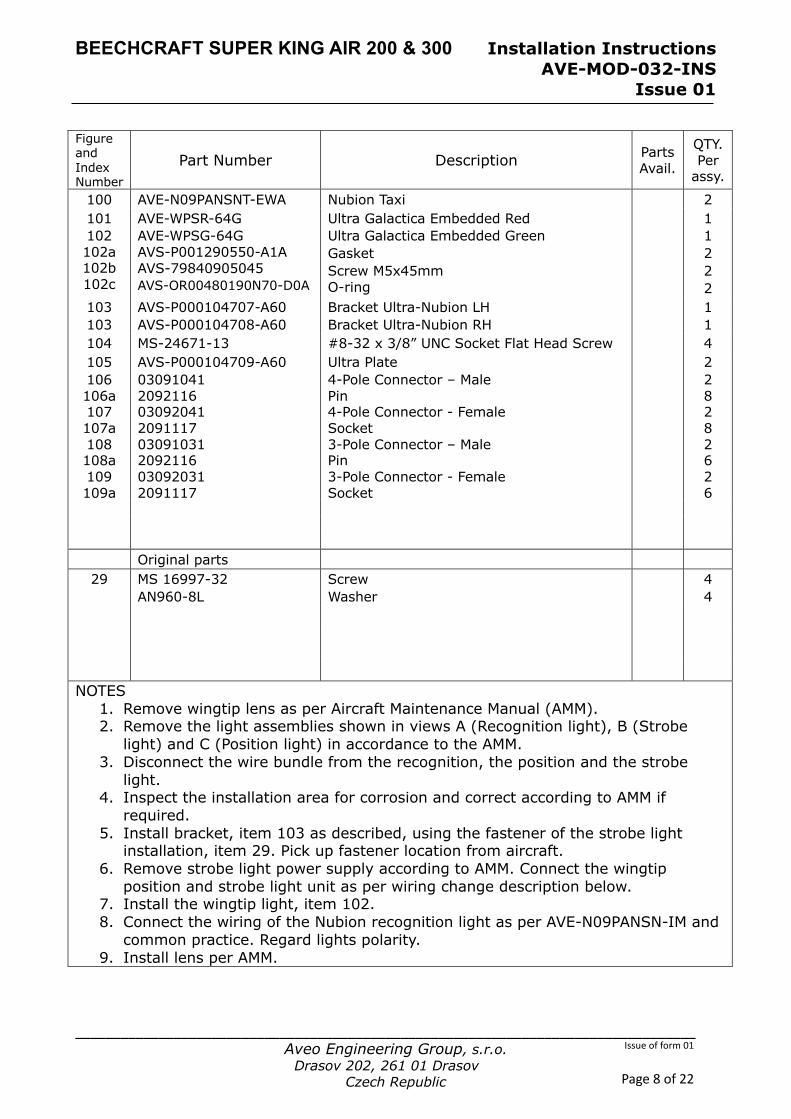
100 AVE-N09PANSNT-EWA Nubion Taxi 2 101 102 102a 102b 102c
AVE-WPSR-64G AVE-WPSG-64G AVS-P001290550-A1A AVS-79840905045 AVS-OR00480190N70-D0A
Ultra Galactica Embedded Red Ultra Galactica Embedded Green Gasket Screw M5x45mm O-ring
1 1 2 2 2
103 103
AVS-P000104707-A60 AVS-P000104708-A60
Bracket Ultra-Nubion LH Bracket Ultra-Nubion RH
1 1
104 MS-24671-13 #8-32 x 3/8” UNC Socket Flat Head Screw 4 105 AVS-P000104709-A60 Ultra Plate 2 106 106a 107 107a 108 108a 109 109a
03091041 2092116 03092041 2091117 03091031 2092116 03092031 2091117
4-Pole Connector – Male Pin 4-Pole Connector - Female Socket 3-Pole Connector – Male Pin 3-Pole Connector - Female Socket
2 8 2 8 2 6 2 6
Original parts 29 MS 16997-32
AN960-8L Screw Washer
4 4
NOTES 1. Remove wingtip lens as per Aircraft Maintenance Manual (AMM). 2. Remove the light assemblies shown in views A (Recognition light), B (Strobe
light) and C (Position light) in accordance to the AMM. 3. Disconnect the wire bundle from the recognition, the position and the strobe
light. 4. Inspect the installation area for corrosion and correct according to AMM if
required. 5. Install bracket, item 103 as described, using the fastener of the strobe light
installation, item 29. Pick up fastener location from aircraft. 6. Remove strobe light power supply according to AMM. Connect the wingtip
position and strobe light unit as per wiring change description below. 7. Install the wingtip light, item 102. 8. Connect the wiring of the Nubion recognition light as per AVE-N09PANSN-IM and
common practice. Regard lights polarity. 9. Install lens per AMM.
BEECHCRAFT SUPER KING AIR 200 & 300 Installation Instructions AVE-MOD-032-INS
Issue 01
__________________________________________________________________________________ Aveo Engineering Group, s.r.o.
Drasov 202, 261 01 Drasov Czech Republic
Issue of form 01
Page 9 of 22
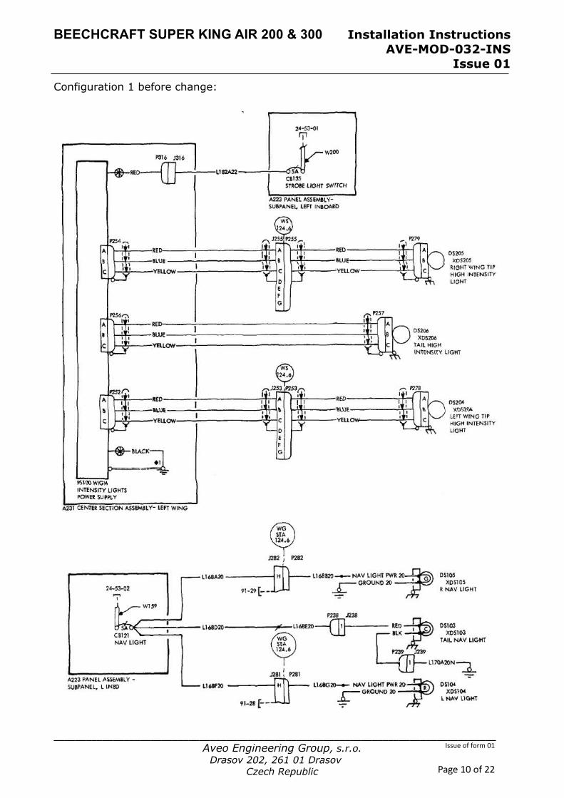
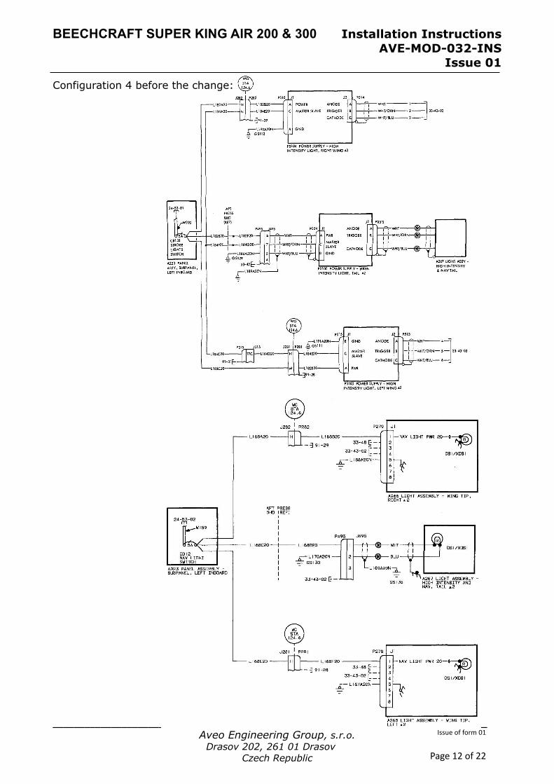
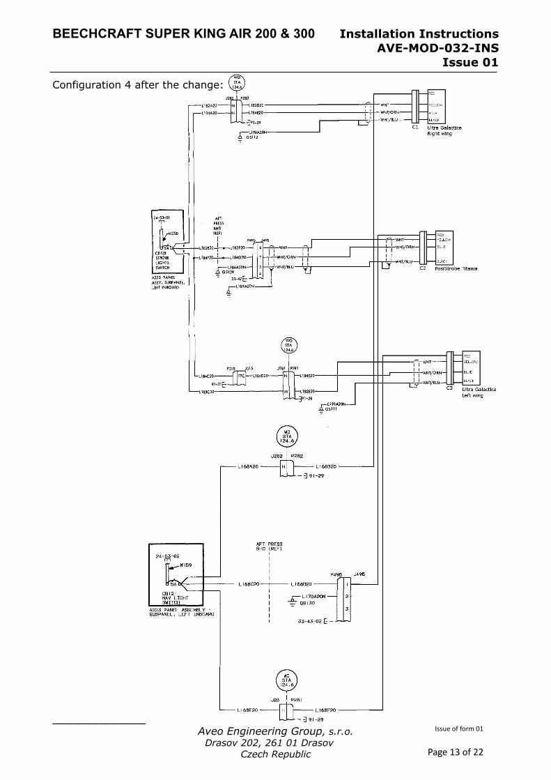
1.4.1 Wiring Change Position and Strobe Lights The original aircraft has separate position and strobe lights installed. These two units are replaced by one unit with the same functionality. The wiring manual of the aircraft covers the following different configurations:
1. One power supply for all three strobes 2. One power supply and removable wingtip / wingtip tanks 3. Three power supplies and removable wingtip / wingtip tanks 4. Three power supplies close to the lights
The more complex part of the wire change is to remove the strobe power supplies and to change the wiring at that location. This is the same for standard configuration and removable wingtip / wingtip tanks configuration. Hence is here shown the configuration 1, which also covers configuration 2 and shown is configuration 4, which also covers configuration 3.
BEECHCRAFT SUPER KING AIR 200 & 300 Installation Instructions AVE-MOD-032-INS
Issue 01
__________________________________________________________________________________ Aveo Engineering Group, s.r.o.
Drasov 202, 261 01 Drasov Czech Republic
Issue of form 01
Page 10 of 22
Configuration 1 before change:
BEECHCRAFT SUPER KING AIR 200 & 300 Installation Instructions AVE-MOD-032-INS
Issue 01
__________________________________________________________________________________ Aveo Engineering Group, s.r.o.
Drasov 202, 261 01 Drasov Czech Republic
Issue of form 01
Page 11 of 22
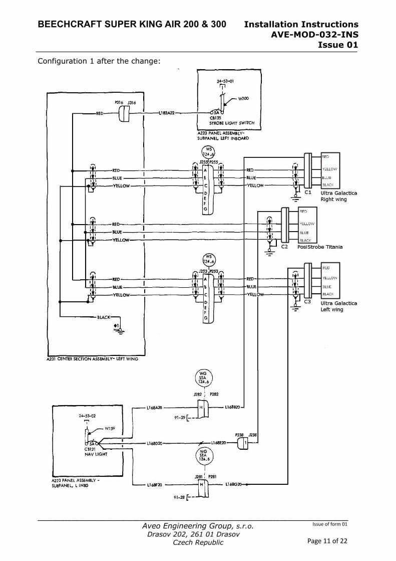
Configuration 1 after the change:
BEECHCRAFT SUPER KING AIR 200 & 300 Installation Instructions AVE-MOD-032-INS
Issue 01
__________________________________________________________________________________ Aveo Engineering Group, s.r.o.
Drasov 202, 261 01 Drasov Czech Republic
Issue of form 01
Page 12 of 22
Configuration 4 before the change:
BEECHCRAFT SUPER KING AIR 200 & 300 Installation Instructions AVE-MOD-032-INS
Issue 01
__________________________________________________________________________________ Aveo Engineering Group, s.r.o.
Drasov 202, 261 01 Drasov Czech Republic
Issue of form 01
Page 13 of 22
Configuration 4 after the change:
BEECHCRAFT SUPER KING AIR 200 & 300 Installation Instructions AVE-MOD-032-INS
Issue 01
__________________________________________________________________________________ Aveo Engineering Group, s.r.o.
Drasov 202, 261 01 Drasov Czech Republic
Issue of form 01
Page 14 of 22
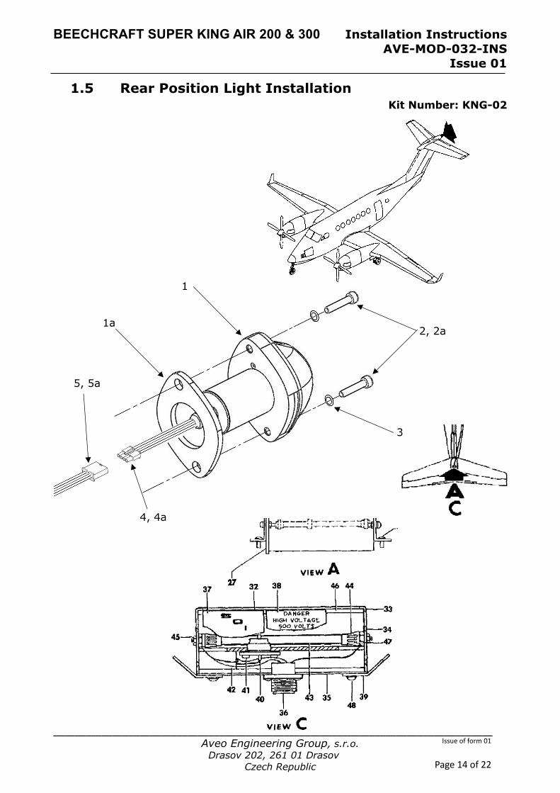
1.5 Rear Position Light Installation Kit Number: KNG-02
1
2, 2a
4, 4a
5, 5a
1a
3
BEECHCRAFT SUPER KING AIR 200 & 300 Installation Instructions AVE-MOD-032-INS
Issue 01
__________________________________________________________________________________ Aveo Engineering Group, s.r.o.
Drasov 202, 261 01 Drasov Czech Republic
Issue of form 01
Page 15 of 22
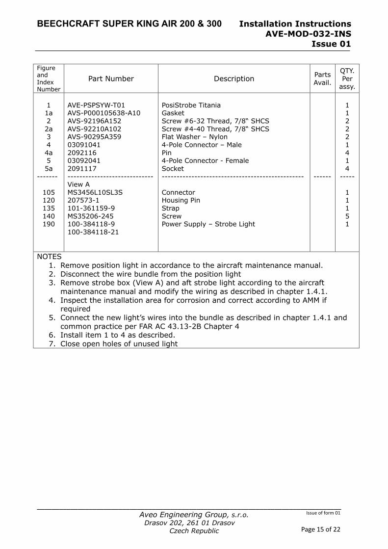
Figure and Index Number
Part Number Description Parts Avail.
QTY. Per
assy. 1 1a 2 2a 3 4 4a 5 5a
-------
105 120 135 140 190
AVE-PSPSYW-T01 AVS-P000105638-A10 AVS-92196A152 AVS-92210A102 AVS-90295A359 03091041 2092116 03092041 2091117 ----------------------------- View A MS3456L10SL3S 207573-1 101-361159-9 MS35206-245 100-384118-9 100-384118-21
PosiStrobe Titania Gasket Screw #6-32 Thread, 7/8“ SHCS Screw #4-40 Thread, 7/8“ SHCS Flat Washer – Nylon 4-Pole Connector – Male Pin 4-Pole Connector - Female Socket ------------------------------------------------ Connector Housing Pin Strap Screw Power Supply – Strobe Light
------
1 1 2 2 2 1 4 1 4
----- 1 1 1 5 1
NOTES 1. Remove position light in accordance to the aircraft maintenance manual. 2. Disconnect the wire bundle from the position light 3. Remove strobe box (View A) and aft strobe light according to the aircraft
maintenance manual and modify the wiring as described in chapter 1.4.1. 4. Inspect the installation area for corrosion and correct according to AMM if
required 5. Connect the new light’s wires into the bundle as described in chapter 1.4.1 and
common practice per FAR AC 43.13-2B Chapter 4 6. Install item 1 to 4 as described. 7. Close open holes of unused light
BEECHCRAFT SUPER KING AIR 200 & 300 Installation Instructions AVE-MOD-032-INS
Issue 01
__________________________________________________________________________________ Aveo Engineering Group, s.r.o.
Drasov 202, 261 01 Drasov Czech Republic
Issue of form 01
Page 16 of 22
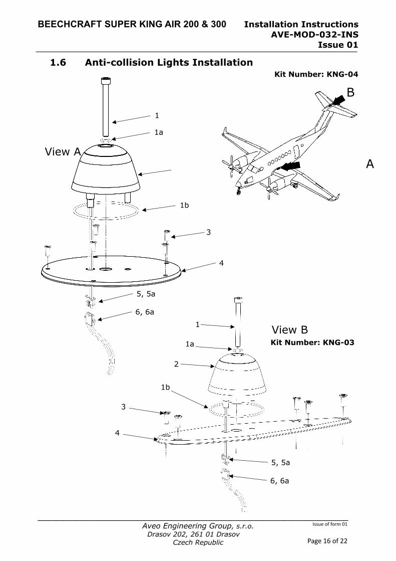
1.6 Anti-collision Lights Installation Kit Number: KNG-04
B
A View A
View B
1
2
3
1
2
3
4
4
5, 5a
6, 6a
5, 5a
6, 6a
Kit Number: KNG-03
1b
1b
1a
1a

BEECHCRAFT SUPER KING AIR 200 & 300 Installation Instructions AVE-MOD-032-INS
Issue 01
__________________________________________________________________________________ Aveo Engineering Group, s.r.o.
Drasov 202, 261 01 Drasov Czech Republic
Issue of form 01
Page 17 of 22
Figure and Index Number
Part Number Description Parts Avail.
QTY. Per
assy. A 1 1a 1b 2 3 4 5 5a 6 6a B 1 1a 1b 2 3 4 5 5a 6 6a
AVS-79840905050 AVS-170299005 AVS-OR05302N70-D0A AVE-RBXPR-001 MS24693-S28 AVS- P000600093-A60 03091031 2092116 03092031 2091117 AVS-79840905050 AVS-170299005 AVS-OR05302N70-D0A AVE-RBXPR-001 MS 24694-S50 AVS- P000600092-A60 03091031 2092116 03092031 2091117
BOTTOM ANTI-COLLISION LIGHT INSTALLATION Screw M5x50mm Flat Washer – Nylon O-Ring RedBaron XP Galactica Original Fasteners RedBaron XP Light Replacement Adapter 2 3-Pole Connector – Male Pin 3-Pole Connector - Female Socket UPPER ANTI-COLLISION LIGHT INSTALLATION Screw M5x50mm Flat Washer – Nylon O-Ring RedBaron XP Galactica Original Fasteners RedBaron XP Light Replacement Adapter 1 3-Pole Connector – Male Pin 3-Pole Connector - Female Socket
1 1 1 1 5 1 1 3 1 3 1 1 1 1 4 1 1 3 1 3
NOTES 1. Remove A523 lower flashing beacon in accordance to the aircraft maintenance
manual. 2. Disconnect the wire bundle from the flashing beacon 3. Inspect the installation area for corrosion and correct according to AMM if
required 4. Splice the new light’s wires into the bundle according to the referenced
installation manuals and the common practice FAR AC 43.13-2B Chapter 4 5. Install item A1 to 5 as described in view A. Drill hole to substructure for anti-
rotation pin as required. 6. Remove A524 upper flashing beacon in accordance to the aircraft maintenance
manual. 7. Disconnect the wire bundle from the flashing beacon 8. Splice the new light’s wires into the bundle according to the referenced
installation manuals and the common practice FAR AC 43.13-2B Chapter 4 9. Install item B1 to 5 as described in view B. Drill hole to substructure for anti-
rotation pin as required.
BEECHCRAFT SUPER KING AIR 200 & 300 Installation Instructions AVE-MOD-032-INS
Issue 01
__________________________________________________________________________________ Aveo Engineering Group, s.r.o.
Drasov 202, 261 01 Drasov Czech Republic
Issue of form 01
Page 18 of 22
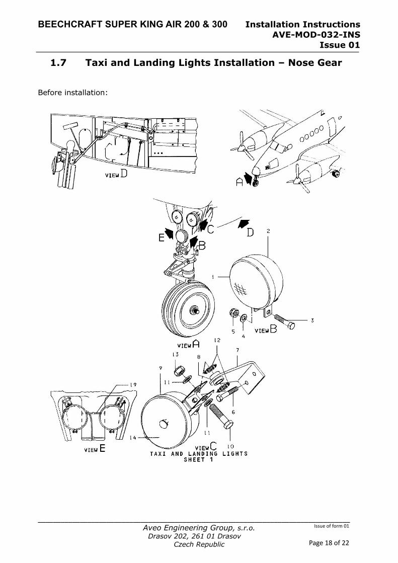
1.7 Taxi and Landing Lights Installation – Nose Gear Before installation:
BEECHCRAFT SUPER KING AIR 200 & 300 Installation Instructions AVE-MOD-032-INS
Issue 01
__________________________________________________________________________________ Aveo Engineering Group, s.r.o.
Drasov 202, 261 01 Drasov Czech Republic
Issue of form 01
Page 19 of 22
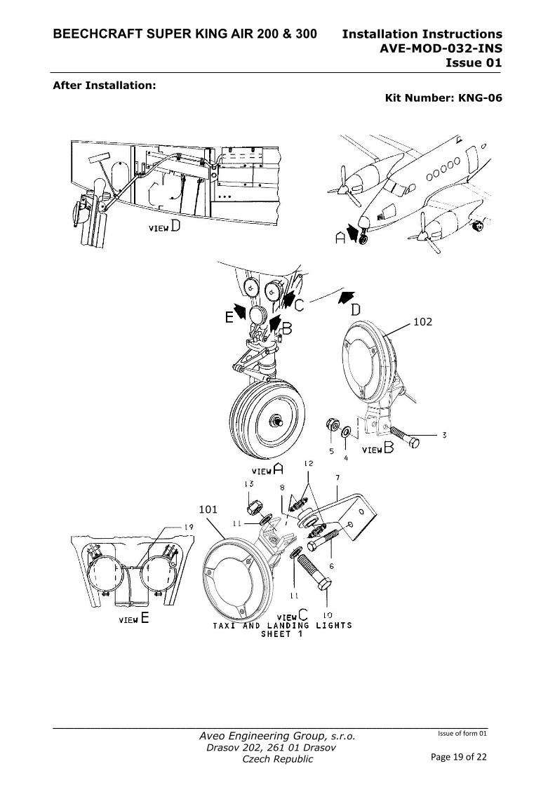
After Installation: Kit Number: KNG-06
102
101
BEECHCRAFT SUPER KING AIR 200 & 300 Installation Instructions AVE-MOD-032-INS
Issue 01
__________________________________________________________________________________ Aveo Engineering Group, s.r.o.
Drasov 202, 261 01 Drasov Czech Republic
Issue of form 01
Page 20 of 22
Figure and Index Number
Part Number Description Parts Avail.
QTY. Per
assy.
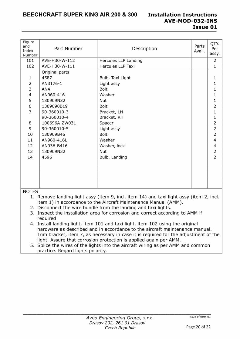
101 AVE-H30-W-112 Hercules LLP Landing 2 102 AVE-H30-W-111 Hercules LLP Taxi 1
Original parts 1 4587 Bulb, Taxi Light 1 2 AN3176-1 Light assy 1 3 AN4 Bolt 1 4 AN960-416 Washer 1 5 130909N32 Nut 1 6 1309090B19 Bolt 2 7 90-360010-3
90-360010-4 Bracket, LH Bracket, RH
1 1
8 100696A-ZW031 Spacer 2 9 90-360010-5 Light assy 2 10 130909B46 Bolt 2 11 AN960-416L Washer 4 12 AN936-B416 Washer, lock 4 13 130909N32 Nut 2 14 4596 Bulb, Landing 2
NOTES 1. Remove landing light assy (item 9, incl. item 14) and taxi light assy (item 2, incl.
item 1) in accordance to the Aircraft Maintenance Manual (AMM). 2. Disconnect the wire bundle from the landing and taxi lights. 3. Inspect the installation area for corrosion and correct according to AMM if
required 4. Install landing light, item 101 and taxi light, item 102 using the original
hardware as described and in accordance to the aircraft maintenance manual. Trim bracket, item 7, as necessary in case it is required for the adjustment of the light. Assure that corrosion protection is applied again per AMM.
5. Splice the wires of the lights into the aircraft wiring as per AMM and common practice. Regard lights polarity.

BEECHCRAFT SUPER KING AIR 200 & 300 Installation Instructions AVE-MOD-032-INS
Issue 01
__________________________________________________________________________________ Aveo Engineering Group, s.r.o.
Drasov 202, 261 01 Drasov Czech Republic
Issue of form 01
Page 21 of 22
Part 2 Compliance demonstration This document is in relation to the certification program AVE-MOD-032-PFC. The compliance is demonstrated for the following certification specification: Requirements MoC Statement of Compliance
CS 23.2250 Design and construction principles
MoC 0 CS 23.603 (a) All materials used are common tested materials. (b) No strength and other property data has been used for this modification. (c) The environmental conditions have been regarded for the selection of materials and the surface treatment.
CS 23.2260 Materials and processes
MoC 0 CS 23.603 (a) All materials used are common tested materials. (b) No strength and other property data has been used for this modification. (c) The environmental conditions have been regarded for the selection of materials and the surface treatment. CS 23.605 (a) The fabrication methods for composite parts is defined in our POE. (b) Is not applicable as the fabrication method is common knowledge and the parts are not load carrying. CS 23.613 (a) to (e) Is not applicable as the parts are nonstructural. The design values used are very conservative and do not require a premium selection of the material. The materials are widely common materials with better properties than the original part. No failure can have a catastrophic consequence and the material also is not fatigue critical.
CS 23.2335 Lightning protection
MoC 0 CS 23.0867 Specific PNs of the lights installed were not tested for lightning direct effects as per Section 23.0 of RTCA DO-160G, therefore compliance with paragraph 23.867 was not demonstrated in this project. CS 23.1365 (a) The only additional wire to be installed is the synchronization wire which is only a signal wire and does not transfer power. (b) The installed equipment is thermally protected. (c)The additional wire is spliced to the light and therefore identified. (d) The wire is to be installed along the existing wiring which is an approved location. (e), (f) not applicable

BEECHCRAFT SUPER KING AIR 200 & 300 Installation Instructions AVE-MOD-032-INS
Issue 01
__________________________________________________________________________________ Aveo Engineering Group, s.r.o.
Drasov 202, 261 01 Drasov Czech Republic
Issue of form 01
Page 22 of 22
Requirements MoC Statement of Compliance
CS 23.2500 General requirements on systems and equipment function
MoC 0 CS 23.1301 (a) All navigation and anti-collision lights are ETSO certified. All landing lights are qualified according to RTCA DO160 as per AVE-H30-001-CCL. (b) No changes are made which would require a changed or a new label. The equipment is labelled to be identified and with its limitation. (c) All equipment is installed within their limits. (d) The proper function is determined in a ground check as per MCS. The improved visibility had been demonstrated in document AVE-MOD-004-SR. CS 23.1309 (a) All products have been tested to the appropriate environmental standard. In addition to that improves the new light installation the mean time between failure by a factor of about 1000. All lights are brighter at lower power consumption and a much lower temperature.
CS 23.2625 Instructions for Continued Airworthiness
MoC 0 CS 23.1529 The modification includes a supplement to the King Air 200 & 300 Aircraft Maintenance Manual (AMM) modified by the AMM Supplement.


