238-48146-00A REV 6/09 INSTALLATION INSTRUCTIONS FOR FLEXIBLE VENT KIT PART NUMBER 239-47812-00 This vent kit is designed to bring all air for combustion from the outside and vent all the combustion products to the outside when properly installed. This vent kit should only be used with direct vent water heaters that were designed for use with this vent kit. Refer to the label on the water heater to determine if this kit is the correct kit for the water heater that you are installing. Consult the supplier of the water heater if you are not certain that this is the correct vent kit. Refer to the information in these instructions and the instructions provided with the water heater when determining the location of the vent terminal and water heater. The vent system must terminate so that proper clearances are maintained as cited in local codes or the latest edition of the National Fuel Gas Code , ANSI Z223.1 as follows: 1. Do not terminate near soffit vents or crawl space or other area where condensate or vapor could create a nuisance or hazard or cause property damage. 2. Do not terminate the exhaust vent terminal where condensate or vapor could cause damage or could be detrimental to the operation of regulators, relief valves, or other equipment. 3. Do not terminate the exhaust vent terminal over public area or walkways where condensate or vapor can cause nuisance or hazard. 4. The vent shall terminate a minimum of 12 inches (30.5 cm) above expected snowfall level to prevent blockage of vent termination. Vent pipes serving direct vent appliances are classified by building codes as “vent connectors”. Required clearances from combustible materials must be provided in accordance with information in this manual under LOCATION OF WATER HEATER and CLEARANCES, and with National Fuel Gas Code and local code. WARNING The vent-air intake system must be properly installed. Failure to properly install the vent-air intake system could result in property damage, personal injury or death. DO NOT install any damaged vent-air intake system components. Contact the manufacturer of the water heater for replacement parts.
Transcript
238-48146-00A REV 6/09
INSTALLATION INSTRUCTIONS FOR FLEXIBLE VENT KIT PART NUMBER
239-47812-00
This vent kit is designed to bring all air for combustion from the outside and vent all the combustion products to the outside when properly installed. This vent kit should only be used with direct vent water heaters that were designed for use with this vent kit. Refer to the label on the water heater to determine if this kit is the correct kit for the water heater that you are installing. Consult the supplier of the water heater if you are not certain that this is the correct vent kit. Refer to the information in these instructions and the instructions provided with the water heater when determining the location of the vent terminal and water heater. The vent system must terminate so that proper clearances are maintained as cited in local codes or the latest edition of the National Fuel Gas Code, ANSI Z223.1 as follows: 1. Do not terminate near soffit vents or crawl space or other area where
condensate or vapor could create a nuisance or hazard or cause property damage.
2. Do not terminate the exhaust vent terminal where condensate or vapor could cause damage or could be detrimental to the operation of regulators, relief valves, or other equipment.
3. Do not terminate the exhaust vent terminal over public area or walkways where condensate or vapor can cause nuisance or hazard.
4. The vent shall terminate a minimum of 12 inches (30.5 cm) above expected snowfall level to prevent blockage of vent termination.
Vent pipes serving direct vent appliances are classified by building codes as “vent connectors”. Required clearances from combustible materials must be provided in accordance with information in this manual under LOCATION OF WATER HEATER and CLEARANCES, and with National Fuel Gas Code and local code.
WARNING The vent-air intake system must be properly installed. Failure to properly install the vent-air intake system could result in property damage, personal injury or death. DO NOT install any damaged vent-air intake system components. Contact the manufacturer of the water heater for replacement parts.
2
Figure 1 Direct Vent Terminal Clearances
Canadian Installations1 US Installations2
A= Clearance above grade, veranda, porch, deck or balcony 12 inches (30.5 cm) 12 inches (30.5 cm) B= Clearance to widow or door that may be opened 12 inches (30.5 cm) 9 inches (23 cm) C= Clearance to permanently closed widow *b *b
D= Vertical clearance to ventilated soffit located above the terminal within a horizontal distance of 2 feet (61 cm) from the center line of the terminal
F= Clearance to outside corner *b *b G= Clearance to inside corner *b *b
H= Clearance to each side of center line extended above meter/regulator assembly
3 feet (.9 m) within a height 15 feet (4.6 m) above the meter/regulator assembly
*b
I= Clearance to service regulator vent outlet or oil tank vent 36 inches (91 cm) *b
J= Clearance to non-mechanical air supply inlet to building or the combustion air inlet to any other appliance 12 inches (30.5 cm) 9 inches (22.8 cm)
K= Clearance to a mechanical air supply inlet 6 feet (1.8 m) 3 feet (.9 m) above if
within 10 feet horizontally
L= Clearance above paved sidewalk or paved driveway located on public property 7 feet (2.1 m)† *b
M= Clearance under a veranda, porch, deck, or balcony 12 inches (30.5 cm)‡ *b
1 In accordance with the current CAN/CGA-B149 Installation Codes. 2 In accordance with the current ANSI Z223.1-(Latest edition)/NFPA 54 National Fuel Gas Code. † A vent shall not terminate directly above a sidewalk or paved driveway that is located between two single-family dwellings and serves both dwellings. ‡ Permitted only if a veranda, porch, deck or balcony is fully open on a minimum of two sides beneath the floor. *a) A minimum clearance value determined by testing in accordance with section 2.20. *b) “Clearance in accordance with local installation codes and the requirements of the gas supplier”.
3
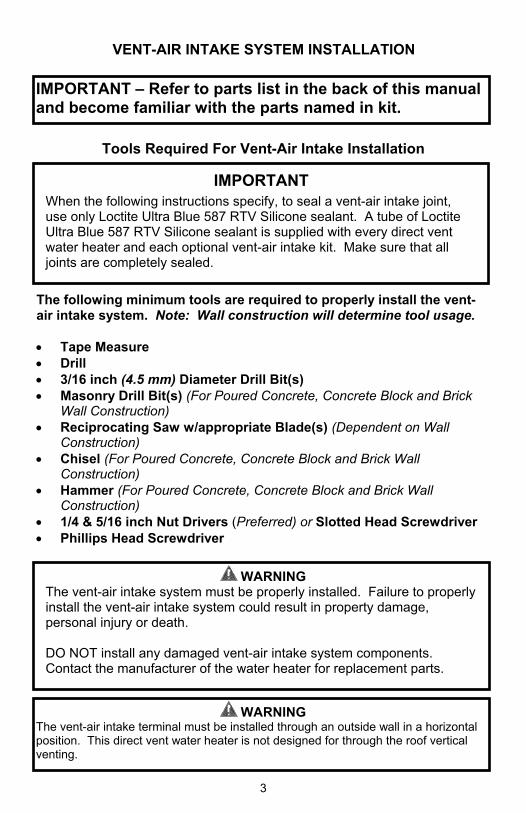
IMPORTANT When the following instructions specify, to seal a vent-air intake joint, use only Loctite Ultra Blue 587 RTV Silicone sealant. A tube of Loctite Ultra Blue 587 RTV Silicone sealant is supplied with every direct vent water heater and each optional vent-air intake kit. Make sure that all joints are completely sealed.
WARNING The vent-air intake system must be properly installed. Failure to properly install the vent-air intake system could result in property damage, personal injury or death. DO NOT install any damaged vent-air intake system components. Contact the manufacturer of the water heater for replacement parts.
IMPORTANT – Refer to parts list in the back of this manual and become familiar with the parts named in kit.
WARNING The vent-air intake terminal must be installed through an outside wall in a horizontal position. This direct vent water heater is not designed for through the roof vertical venting.
VENT-AIR INTAKE SYSTEM INSTALLATION
Tools Required For Vent-Air Intake Installation
The following minimum tools are required to properly install the vent-air intake system. Note: Wall construction will determine tool usage. • Tape Measure • Drill • 3/16 inch (4.5 mm) Diameter Drill Bit(s) • Masonry Drill Bit(s) (For Poured Concrete, Concrete Block and Brick
Wall Construction) • Reciprocating Saw w/appropriate Blade(s) (Dependent on Wall
Construction) • Hammer (For Poured Concrete, Concrete Block and Brick Wall Construction) • 1/4 & 5/16 inch Nut Drivers (Preferred) or Slotted Head Screwdriver • Phillips Head Screwdriver
4
FIGURE 2 1. Measure the vertical height “Y” required in your installation. (See Figure
2). 2. Measure the horizontal length “X” required in your installation (See
Figure 2). 3. Add the X & Y dimensions together. If the sum is less than 100 inches
(254 cm) and equal to or greater than 44 inches (111.7 cm) the flexible vent can be used with out cutting the flexible vent by stretching or compressing the flexible vent. If the length is less than 44 inches (111.7 cm) the interior 3 inch (7.6 cm) vent can be trimmed to length. If the length is greater than 100 inches (254 cm) this flexible vent kit will not work with the water heater location. Either adjust the location of the water heater or contact your supplier for options.
WARNING Do not attempt to use flexible vent hose at distance greater than 100 inches (254 cm).
5
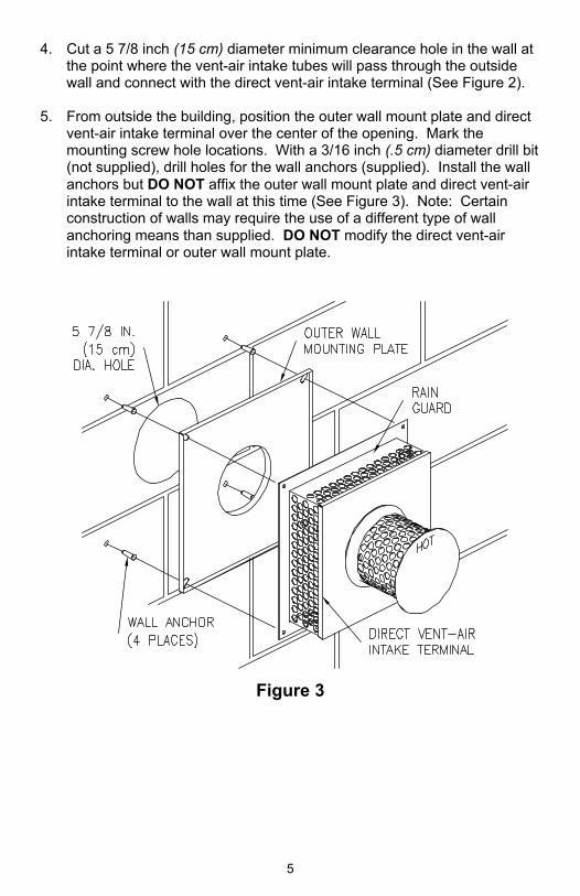
4. Cut a 5 7/8 inch (15 cm) diameter minimum clearance hole in the wall at the point where the vent-air intake tubes will pass through the outside wall and connect with the direct vent-air intake terminal (See Figure 2).
5. From outside the building, position the outer wall mount plate and direct
vent-air intake terminal over the center of the opening. Mark the mounting screw hole locations. With a 3/16 inch (.5 cm) diameter drill bit (not supplied), drill holes for the wall anchors (supplied). Install the wall anchors but DO NOT affix the outer wall mount plate and direct vent-air intake terminal to the wall at this time (See Figure 3). Note: Certain construction of walls may require the use of a different type of wall anchoring means than supplied. DO NOT modify the direct vent-air intake terminal or outer wall mount plate.
Figure 3
6
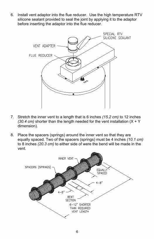
6. Install vent adaptor into the flue reducer. Use the high temperature RTV silicone sealant provided to seal the joint by applying it to the adaptor before inserting the adaptor into the flue reducer.
7. Stretch the inner vent to a length that is 6 inches (15.2 cm) to 12 inches
(30.4 cm) shorter than the length needed for the vent installation (X + Y dimension).
8. Place the spacers (springs) around the inner vent so that they are
equally spaced. Two of the spacers (springs) must be 4 inches (10.1 cm) to 8 inches (20.3 cm) to either side of were the bend will be made in the vent.
7
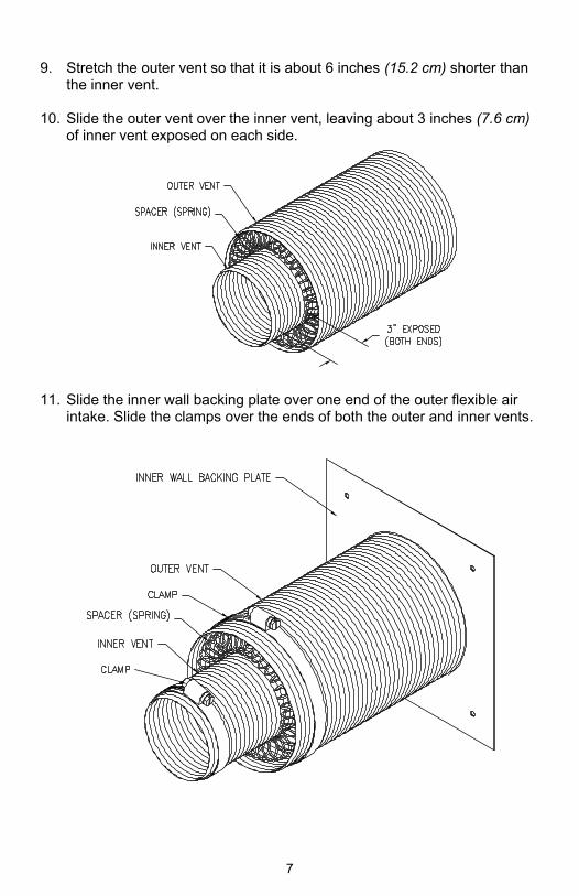
9. Stretch the outer vent so that it is about 6 inches (15.2 cm) shorter than
the inner vent. 10. Slide the outer vent over the inner vent, leaving about 3 inches (7.6 cm)
of inner vent exposed on each side.
11. Slide the inner wall backing plate over one end of the outer flexible air
intake. Slide the clamps over the ends of both the outer and inner vents.
8
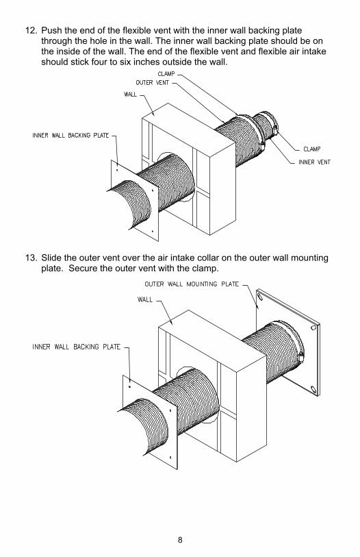
12. Push the end of the flexible vent with the inner wall backing plate through the hole in the wall. The inner wall backing plate should be on the inside of the wall. The end of the flexible vent and flexible air intake should stick four to six inches outside the wall.
13. Slide the outer vent over the air intake collar on the outer wall mounting
plate. Secure the outer vent with the clamp.
9
14. Apply a bead of the special RTV silicon sealant to the exhaust collar on
the vent terminal.
15. Slide the inner vent over the vent terminal collar. Secure the inner vent
with the clamp.
10
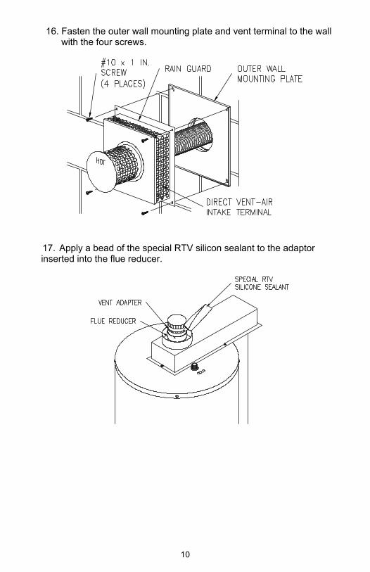
16. Fasten the outer wall mounting plate and vent terminal to the wall with the four screws.
17. Apply a bead of the special RTV silicon sealant to the adaptor inserted into the flue reducer.
11
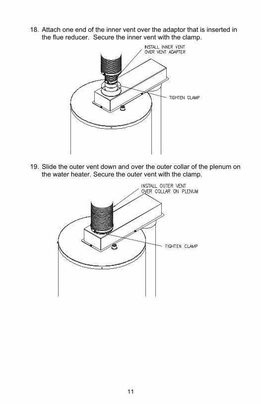
18. Attach one end of the inner vent over the adaptor that is inserted in
the flue reducer. Secure the inner vent with the clamp.
19. Slide the outer vent down and over the outer collar of the plenum on the water heater. Secure the outer vent with the clamp.
12
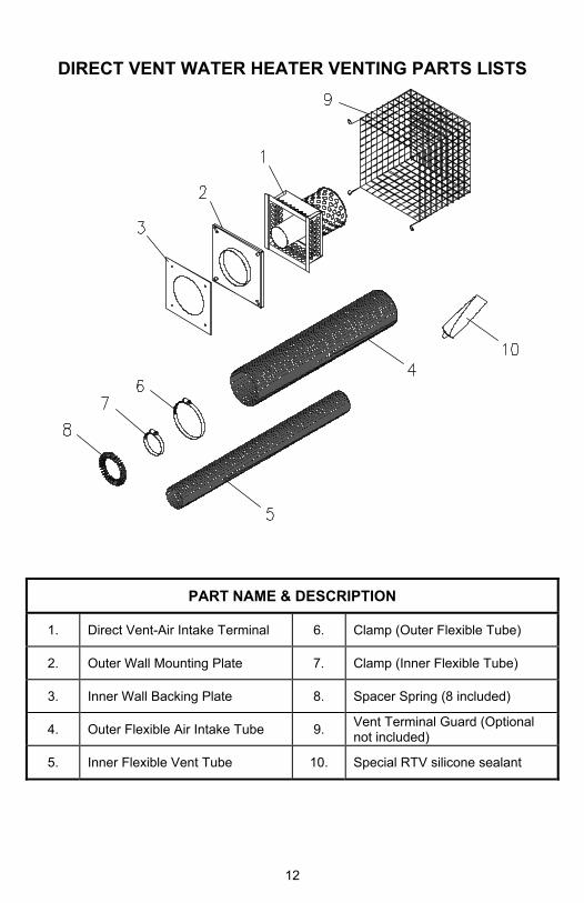
DIRECT VENT WATER HEATER VENTING PARTS LISTS
PART NAME & DESCRIPTION
1. Direct Vent-Air Intake Terminal 6. Clamp (Outer Flexible Tube)