(Type FSP CATEGORY IV Director Non Direct Vent Air Furnace)
These furnaces comply with requirements em-bodied in the American National Standard / Na-tional Standard of Canada ANSI Z21.47·CSA-2.3Gas Fired Central Furnaces.
Installer:Affix all manuals
adjacent to the unit.
As a professional installer you have an obligation to knowthe product better than the customer. This includes all safetyprecautions and related items.
Prior to actual installation, thoroughly familiarize yourselfwith this Instruction Manual. Pay special attention to allsafety warnings. Often during installation or repair it ispossible to place yourself in a position which is morehazardous than when the unit is in operation.
Remember, it is your responsibility to install the productsafely and to know it well enough to be able to instruct acustomer in its safe use.
Safety is a matter of common sense...a matter of thinkingbefore acting. Most dealers have a list of specific goodsafety practices...follow them.
The precautions listed in this Installation Manual are intendedas supplemental to existing practices. However, if there isa direct conflict between existing practices and the contentof this manual, the precautions listed here take precedence.
CONDENSATE DRAIN LINES & DRAIN TRAP ...................... 18GENERAL DRAIN INFORMATION ........................................ 19FIELD SUPPLIED DRAIN .............................................. 19UPFLOW MODEL INSTALLED VERTICALLY ............................... 20DRAIN EXITING RIGHT SIDE .......................................... 20DRAIN EXITING LEFT SIDE ........................................... 20UPFLOW MODEL INSTALLED HORIZONTALLY
WITH RIGHT SIDE DOWN.......................................... 20UPFLOW MODEL INSTALLED HORIZONTALLY
WITH LEFT SIDE DOWN ........................................... 21COUNTERFLOW MODEL INSTALLED VERTICALLY ......................... 21DRAIN EXITING LEFT SIDE ........................................... 21DRAIN EXITING RIGHT SIDE .......................................... 22COUNTERFLOW MODEL INSTALLED HORIZONTALLY
WITH RIGHT SIDE DOWN.......................................... 22COUNTERFLOW MODEL INSTALLED HORIZONTALLY
WITH LEFT SIDE DOWN ........................................... 22
is a registered trademark of Maytag Corporation or its related companies and is usedunder license to Goodman Company, L.P., Houston, TX. All rights reserved.
2
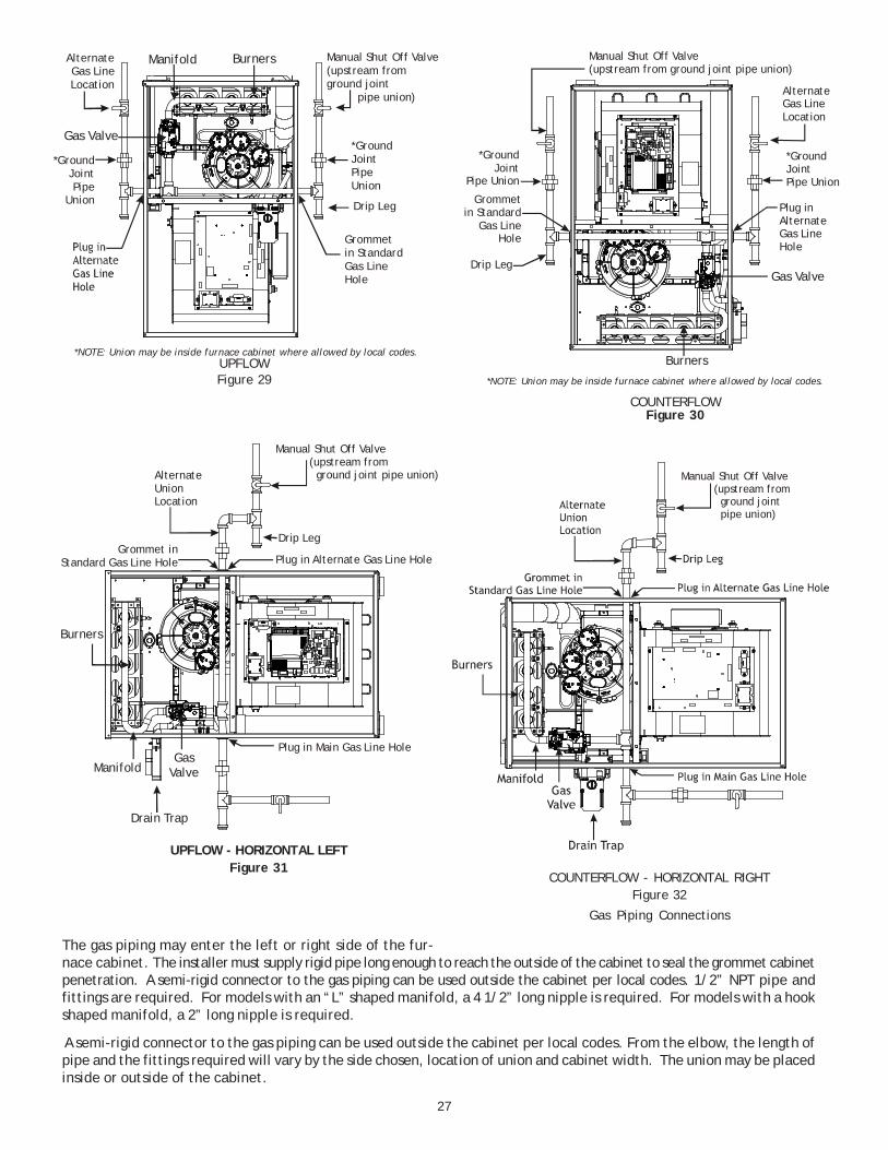
ELECTRICAL CONNECTIONS ....................................... 23WIRING HARNESS ................................................... 23115 VOLT LINE CONNECTIONS ....................................... 23JUNCTION BOX RELOCATION .......................................... 2424 VOLT THERMOSTAT WIRING ...................................... 24SINGLE-STAGE HEATING THERMOSTAT APPLICATION ...................... 24FOSSIL FUEL APPLICATIONS ........................................... 25GAS SUPPLY AND PIPING ............................................ 25HIGH ALTITUDE DERATE ............................................. 25PROPANE GAS CONVERSION .......................................... 25GAS PIPING CONNECTIONS ........................................... 26PROPANE GAS TANKS AND PIPING .................................... 28
CIRCULATING AIR & FILTERS ....................................... 29DUCT WORK - AIR FLOW ............................................ 29CHECKING DUCT STATIC ............................................. 29BOTTOM RETURN AIR OPENING [UPFLOW MODELS] .................... 30FILTERS - READ THIS SECTION BEFORE
INSTALLING THE RETURN AIR DUCT WORK .......................... 30UPRIGHT INSTALLATIONS ............................................. 31HORIZONTAL INSTALLATIONS .......................................... 32
AND ADJUSTMENT ................................................ 33GAS INPUT RATE MEASUREMENT (NATURAL GAS ONLY) ............... 34TEMPERATURE RISE ................................................. 34CIRCULATOR BLOWER SPEEDS ........................................ 35BLOWER HEAT OFF DELAY TIMINGS .................................. 35
NORMAL SEQUENCE OF OPERATION............................. 35POWER UP ........................................................ 35HEATING MODE .................................................... 35COOLING MODE .................................................... 36FAN ONLY MODE .................................................. 36
BEFORE LEAVING AN INSTALLATION .............................. 39REPAIR AND REPLACEMENT PARTS ............................... 40TROUBLESHOOTING CHART....................................... 41AIRFLOW *MSS92*** & *CSS92***A* ............................... 43AIRFLOW *MSS96*** & *CSS96***A* ................................ 44WIRING DIAGRAM ................................................... 46SPECIAL INSTRUCTIONS FOR PRODUCTS INSTALLED
IN THE STATE OF MASSACHUSETTS ........................ 47
3
TO PREVENT PERSONAL INJURY OR DEATH DUE TO IMPROPER INSTALLATION, ADJUSTMENT, ALTERATION, SERVICE OR MAINTENANCE, REFER TO THIS MANUAL. FOR ADDITIONAL ASSISTANCE OR INFORMATION, CONSULT A QUALIFIED INSTALLER, SERVICER AGENCY OR THE GAS SUPPLIER.
WARNING
IF THE INFORMATION IN THESE INSTRUCTIONS IS NOT FOLLOWED EXACTLY, A FIRE OR EXPLOSION MAY RESULT CAUSING PROPERTYDAMAGE, PERSONAL INJURY OR LOSS OF LIFE.
DO NOT STORE OR USE GASOLINE OR OTHER FLAMMABLE VAPORS AND LIQUIDS IN THE VICINITY OF THIS OR ANY OTHER APPLIANCE.
DO NOT TRY TO LIGHT ANY APPLIANCE.DO NOT TOUCH ANY ELECTRICAL SWITCH; DO NOT USE ANY PHONE IN YOUR BUILDING.IMMEDIATELY CALL YOUR GAS SUPPLIER FROM A NEIGHBOR’S PHONE. FOLLOW THE GAS SUPPLIER’S INSTRUCTIONS.IF YOU CANNOT REACH YOUR GAS SUPPLIER, CALL THE FIRE DEPARTMENT.
INSTALLATION AND SERVICE MUST BE PERFORMED BY A QUALIFIED INSTALLER, SERVICE AGENCY OR THE GAS SUPPLIER.
WHAT TO DO IF YOU SMELL GAS:
WARNING
THIS PRODUCT CONTAINS OR PRODUCES A CHEMICAL OR CHEMICALS WHICH MAY CAUSE SERIOUS ILLNESS OR DEATH AND WHICH ARE KNOWN TO THE STATE OF CALIFORNIA TO CAUSE CANCER, BIRTH DEFECTS OR OTHER REPRODUCTIVE HARM.
WARNING
HEATING UNIT SHOULD NOT BE UTILIZED WITHOUT REASONABLE, ROUTINE, INSPECTION, MAINTENANCE AND SUPERVISION. IF THE BUILDING IN WHICH ANY SUCH DEVICE IS LOCATED WILL BE VACANT, CARE SHOULD BE TAKEN THAT SUCH DEVICE IS ROUTINELY INSPECTED, MAINTAINED AND MONITORED. IN THE EVENT THAT THE BUILDING MAYBE EXPOSED TO FREEZING TEMPERATURES AND WILL BE VACANT, ALL WATER-BEARING PIPES SHOULD BE DRAINED, THE BUILDING SHOULD BE PROPERLY WINTERIZED, AND THE WATER SOURCE CLOSED. IN THE EVENT THAT THE BUILDING MAY BE EXPOSED TO FREEZING TEMPERATURES AND WILL BE VACANT, ANY HYDRONIC COIL UNITS SHOULD BE DRAINED AS WELL AND, IN SUCH CASE, ALTERNATIVE HEAT SOURCES SHOULD BE UTILIZED.
WARNING
TO PREVENT POSSIBLE PROPERTY DAMAGE, PERSONAL INJURY OR DEATH DUE TO ELECTRICAL SHOCK, THE FURNACE MUST BE LOCATED TO PROTECT THE ELECTRICAL COMPONENTS FROM WATER.
WARNING
Drain trap must be primed at time of installation. Trap isinternally partitioned; add water to both inlet ports until wa-ter appears at both sides of the outlet opening. Failure toprime trap at time of installation may have a negative ef-fect on combustion quality and pressure switch action.
GOODMAN WILL NOT BE RESPONSIBLE FOR ANY INJURY OR PROPERTY DAMAGE ARISING FROM IMPROPER SERVICE OR SERVICE PROCEDURES. IF YOU INSTALL OR PERFORM SERVICE ON THIS UNIT, YOU ASSUME RESPONSIBILITY FOR ANY PERSONAL INJURY OR PROPERTY DAMAGE WHICH MAY RESULT. MANY JURISDICTIONS REQUIRE A LICENSE TO INSTALL OR SERVICE HEATING AND AIR CONDITIONING EQUIPMENT.
WARNING
SAFETY CONSIDERATIONS
Adhere to the following warnings and cautions when install-ing, adjusting, altering, servicing, or operating the furnace.To ensure proper installation and operation, thoroughly readthis manual for specifics pertaining to the installation andapplication of this product.
This furnace is manufactured for use with natural gas. Itmay be field converted to operate on L.P. gas by using theappropriate L.P. conversion kit listed in the PROPANE GAS/HIGH ALTITUDE INSTALLATIONS section of this manual
Install this furnace only in a location and position as speci-fied in LOCATION REQUIREMENTS & CONSIDERATIONS sec-tion and INSTALLATION POSITIONS section of this manual.
Provide adequate combustion and ventilation air to the fur-nace as specified in COMBUSTION & VENTILATION AIR RE-QUIREMENTS section of this manual.
Combustion products must be discharged to the outdoors.Connect this furnace to an approved vent system only, asspecified in VENT/FLUE PIPE & COMBUSTION AIR PIPE sec-tion of this manual.
Never test for gas leaks with an open flame. Use a commer-cially available soap solution made specifically for the detec-tion of leaks to check all connections, as specified in GASSUPPLY AND PIPING section of this manual.
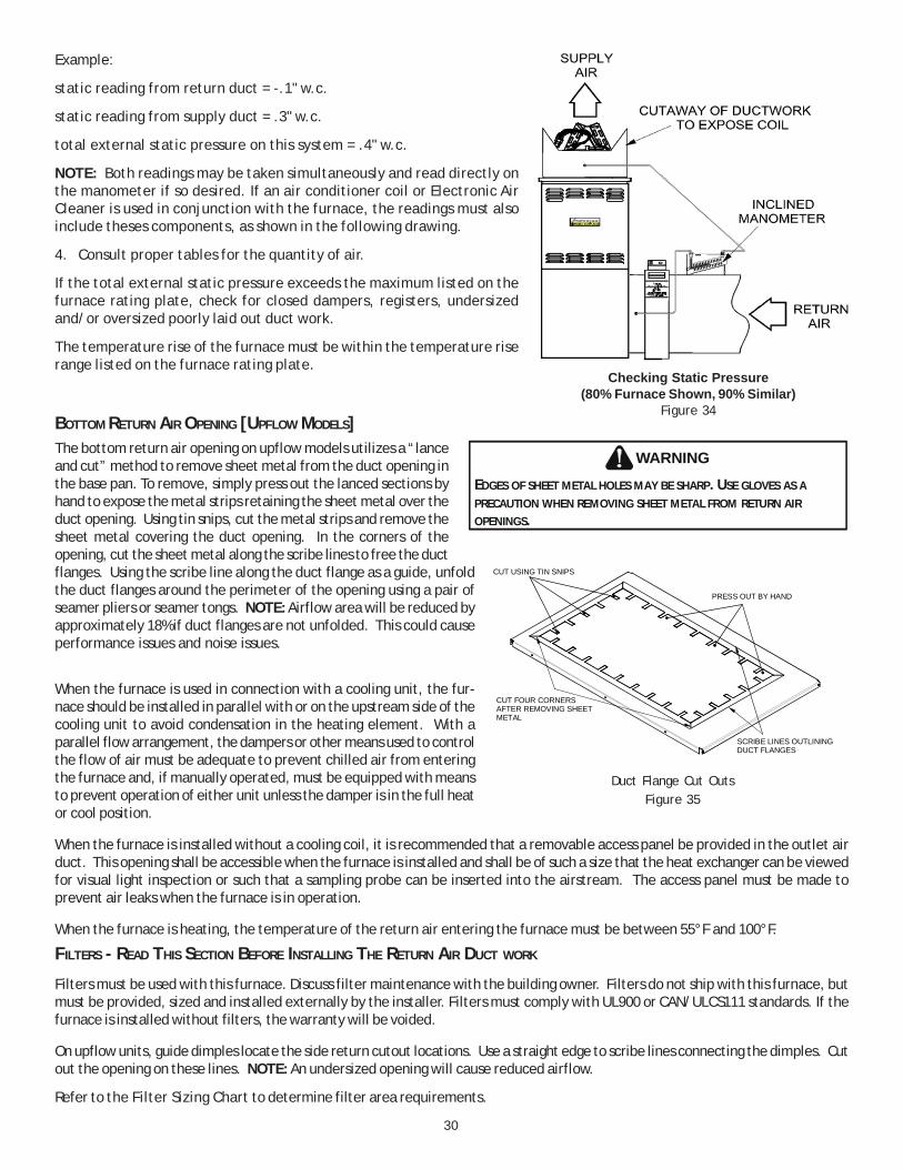
Always install a furnace to operate within the furnace’s in-tended temperature-rise range with a duct system which hasexternal static pressure within the allowable range, as speci-fied on the furnace rating plate and OPERATIONAL CHECKSsection of these instructions.
When a furnace is installed so that supply ducts carry aircirculated by the furnace to areas outside the space contain-ing the furnace, the return air shall also be handled by duct(s)sealed to the furnace casing and terminating outside thespace containing the furnace.
A gas-fired furnace for installation in a residential garagemust be installed as specified in the LOCATION REQUIRE-MENTS AND CONSIDERATIONS section of this manual.
This furnace may be used as a construction site heater onlyif certain conditions are met. These conditions are listed inthe PRODUCT APPLICATION section of this manual.
4
DANGER
0140M00020-D
CARBON MONOXIDE POISONING HAZARDSpecial warning for installation of furnaces or air handling units in enclosed area such as garages, utility rooms or parking areas. Carbon monoxide producingdevices (such as automobile, space heater, gas water heater, etc.) Should not be operated in enclosed areas such as unventilated garages or utility rooms becauseof the danger of carbon monoxide (CO) poisoning resulting from the exhaust emissions. If a furnace or air handler is installed in an enclosed area and a carbonmonoxide producing device is operated therein, there must be adequate direct outside ventilation. Carbon monoxide emissions can be (re)circulated throughoutthe structure if the furnace or air handler is operating in any mode. CO can cause serious illness including permanent brain damage or death.
Avertissement special au sujet de l'installation d'appareils de chauffage ou de traitement d'air dans des endroits clos, tets les garages, les locaux d'entretien et lesRISQUE D'EMPOISONNEMENT AU MONOXYDE DE CARBONE
stationnements. Evitez de mettre en marche les appareils produisant du monoxyde de carbone (tels que les automobile, les appareils de chauffage autonome,etc.)dans des endroits non ventilés tels que les d'empoisonnement au monoxyde de carbone. Si vous devez faire fonctionner ces appareils dans un endroit clos, assures-vous qu'il y ait une ventilation directe provenant de l'exterie . Les émissions de monoxyde de carbone peuvent etre recircules dans les endroits clos, si l'appareil de chauffage ou de traitement d'air sont en marche. Le monoxyde de carbone peut causer des maladies graves telles que des dommages permanents au cerveau et meme la mort.
Advertencia especial para la instalación de calentadores ó maneja oras de aire en áreas cerradas como estacionamientos ó cuartos de servicio. Los equipos óRIESGO DE INTOXICACIÓN POR MONÓXIDO DE CARBONO
aparatos que producen monóxido de carbono (tal como automóvil, calentador de gas, calentador de agua por medio de gas, etc) no deben ser operados enáreas cerradas debido al riesgo de envenenamiento por monóxido de carbono (CO) que resulta de las emisiones de gases de combustión. Si el equipo óaparato se opera en dichas áreas, debe existir una adecuada ventilac ón directa al exterior. Las emisiones de monóxido de carbono pueden circular a travésdel aparato cuando se opera en cualquier modo. El monóxido de carbono puede causar enfermedades severas como daño cerebral permanente ó muerte.
'
DANGER
PELIGRO
POSSIBLE PROPERTY DAMAGE, PERSONAL INJURY OR DEATH DUE TO FIRE, EXPLOSION, SMOKE, SOOT, CONDENSATION, ELECTRICAL SHOCK OR CARBON MONOXIDE MAY RESULT FROM IMPROPER INSTALLATION, REPAIR OPERATION, OR MAINTENANCE OF THIS PRODUCT.
WARNING
SHOULD OVERHEATING OCCUR OR THE GAS SUPPLY FAIL TO SHUT OFF, TURN OFF THE MANUAL GAS SHUTOFF VALVE EXTERNAL TO THE FURNACE BEFORE TURNING OFF THE ELECTRICAL SUPPLY.
WARNING
SHIPPING INSPECTION
All units are securely packed in shipping containers tested accord-ing to International Safe Transit Association specifications. Thecarton must be checked upon arrival for external damage. If dam-age is found, a request for inspection by carrier’s agent must bemade in writing immediately.
The furnace must be carefully inspected on arrival for damage andbolts or screws which may have come loose in transit. In the eventof damage the consignee should:1. Make a notation on delivery receipt of any visible damage to
shipment or container.2. Notify carrier promptly and request an inspection.3. With concealed damage, carrier must be notified as soon as
possible - preferably within five days.4. File the claim with the following support documents within a nine month statute of limitations.• Original or certified copy of the Bill of Lading, or indemnity bond.• Original paid freight bill or indemnity in lieu thereof.• Original or certified copy of the invoice, showing trade and other discounts or reductions.• Copy of the inspection report issued by carrier’s representative at the time damage is reported to carrier.
The carrier is responsible for making prompt inspection of damage and for a thorough investigation of each claim. The distributor ormanufacturer will not accept claims from dealers for transportation damage.
ELECTROSTATIC DISCHARGE (ESD) PRECAUTIONS
NOTE: Discharge your body’s static electricity before touching unit. An electrostatic discharge can adversely affect electricalcomponents.
Use the following precautions during furnace installation and servicing to protect the integrated control module from damage. Byputting the furnace, the control, and the person at the same electrostatic potential, these steps will help avoid exposing theintegrated control module to electrostatic discharge. This procedure is applicable to both installed and non-installed (ungrounded)furnaces.1. Disconnect all power to the furnace. Do not touch the integrated control module or any wire connected to the control prior to
discharging your body’s electrostatic charge to ground.2. Firmly touch a clean, unpainted, metal surface of the furnaces near the control. Any tools held in a person’s hand during
grounding will be discharged.
5
3. Service integrated control module or connecting wiring following the discharge process in step 2. Use caution not to rechargeyour body with static electricity; (i.e., do not move or shuffle your feet, do not touch ungrounded objects, etc.). If you comein contact with an ungrounded object, repeat step 2 before touching control or wires.
4. Discharge your body to ground before removing a new control from its container. Follow steps 1 through 3 if installing thecontrol on a furnace. Return any old or new controls to their containers before touching any ungrounded object.
TO THE INSTALLER
Before installing this unit, please read this manual thoroughly tofamiliarize yourself with specific items which must be adhered to,including but not limited to: unit maximum external static pres-sure, gas pressures, BTU input rating, proper electrical connec-tions, circulating air temperature rise, minimum or maximum CFM,and motor speed connections.
PRODUCT APPLICATION
This furnace is primarily designed for residential home-heating applications. It is NOT designed or certified for use in mobile homes,trailers or recreational vehicles. Neither is it designed or certified for outdoor applications. The furnace must be installed indoors(i.e., attic space, crawl space, or garage area provided the garage area is enclosed with an operating door).
This furnace can be used in the following non-industrial commercial applications:
Schools, Office buildings, Churches, Retail stores, Nursing homes, Hotels/motels, Common or office areas
In such applications, the furnace must be installed with the following stipulations:• It must be installed per the installation instructions provided and per local and national codes.• It must be installed indoors in a building constructed on site.• It must be part of a ducted system and not used in a free air delivery application.• It must not be used as a “make-up” air unit.• It must be installed as a two-pipe systems for combustion air.• All other warranty exclusions and restrictions apply This furnace is an ETL dual-certified appliance and is appropriate for use
with natural or propane gas (NOTE: If using propane, a propane conversion kit is required).
Dual certification means that the combustion air inlet pipe is optional and the furnace can be vented as a:Non-direct vent (single pipe) central forced air furnace in which combustion air is taken from the installation area or fromair ducted from the outside or,Direct vent (dual pipe) central forced air furnace in which all combustion air supplied directly to the furnace burners througha special air intake system outlined in these instructions.
This furnace may be used as a construction site heater ONLY if all of the following conditions are met:• The vent system is permanently installed per these installation instructions.• A room thermostat is used to control the furnace. Fixed jumpers that provide continuous heating CANNOT be used and can
cause long term equipment damage.• Return air ducts are provided and sealed to the furnace.• A return air temperature range between 60ºF (16ºC) and 80ºF (27ºC) is maintained.• Air filters are installed in the system and maintained during construction replaced as appropriate during construction, and
upon completion of construction.• The input rate and temperature rise are set per the furnace rating plate.• 100% outside air is provided for combustion air requirements during construction. Temporary ducting can be used.
NOTE: Do not connect the temporary duct directly to the furnace. The duct must be sized for adequate combustion andventilation in accordance with the latest edition of the National Fuel Gas Code NFPA 54/ANSI Z223.1 or CAN/CSA B149.1Installation Codes.
• The furnace heat exchanger, components, duct system, air filters and evaporator coils are thoroughly cleaned following finalconstruction clean up.
• All furnace operating conditions (including ignition, input rate, temperature rise and venting) are verified according tothese installation instructions.
NOTE: The Commonwealth of Massachusetts requires that the following additional requirements must also be met:• Gas furnaces must be installed by a licensed plumber or gas fitter.
TO PREVENT PROPERTY DAMAGE, PERSONAL INJURY OR DEATH DUE TO FIRE, DO NOT INSTALL THIS FURNACE IN A MOBILE HOME, TRAILER, OR RECREATIONAL VEHICLE.
WARNING
6
• A T-handle gas cock must be used.• If the unit is to be installed in an attic, the passageway to and the service area around the unit must have flooring.
To ensure proper furnace operation, install, operate and maintain the furnace in accordance with these installation andoperation instructions, all local building codes and ordinances. In their absence, follow the latest edition of the National Fuel GasCode (NFPA 54/ANSI Z223.1), and/or CAN/CSA B149 Installation Codes, local plumbing or waste water codes, and other applicablecodes.
A copy of the National Fuel Gas Code (NFPA 54/ANSI Z223.1) can be obtained from any of the following:
American National Standards Institute National Fire Protection Association CSA International 25 West 43rd Street, 4th Floor 1 Batterymarch Park 8501 East Pleasant Valley
New York, NY 10036 Quincy, MA 012169-7471 Independence, OH 44131
The rated heating capacity of the furnace should be greater than or equal to the total heat loss of the area to be heated. The total heatloss should be calculated by an approved method or in accordance with “ASHRAE Guide” or “Manual J-Load Calculations” published bythe Air Conditioning Contractors of America.
A copy of the CAN/CSA B149 Installation Codes can also be obtained from:
Follow the instructions listed below and the guidelines provided in the Combustion and Ventilation Air Requirements section whenselecting a furnace location.
TO PREVENT POSSIBLE EQUIPMENT DAMAGE, PROPERTY DAMAGE, PERSONAL INJURY OR DEATH, THE FOLLOWING BULLET POINTS MUST BE OBSERVED WHEN INSTALLING THIS UNIT.
WARNING
POSSIBLE PROPERTY DAMAGE, PERSONAL INJURY OR DEATH DUE TO FIRE, EXPLOSION, SMOKE, SOOT, CONDENSATION, ELECTRICAL SHOCK OR CARBON MONOXIDE MAY RESULT FROM IMPROPER INSTALLATION, REPAIR OPERATION, OR MAINTENANCE OF THIS PRODUCT.
WARNING
• Centrally locate the furnace with respect to the proposed or existing air distribution system.• Ensure the temperature of the return air entering the furnace is between 55°F and 100°F when the furnace is heating.• Provide provisions for venting combustion products outdoors through a proper venting system. Special consideration should
be given to vent/flue pipe routing and combustion air intake pipe when applicable. Refer to Vent/Flue Pipe and CombustionAir Pipe -Termination Locations for appropriate termination locations and to determine if the piping system from furnace totermination can be accomplished within the guidelines given. NOTE: The length of flue and/or combustion air piping canbe a limiting factor in the location of the furnace.
• Locate the furnace so condensate flows downwards to the drain. Do not locate the furnace or its condensate drainagesystem in any area subject to below freezing temperatures without proper freeze protection. Refer to Condensate DrainLines and Trap for further details.
• Ensure adequate combustion air is available for the furnace. Improper or insufficient combustion air can expose buildingoccupants to gas combustion products that could include carbon monoxide. Refer to Combustion and Ventilation AirRequirements.
• Set the furnace on a level floor to enable proper condensate drainage. If the floor becomes wet or damp at times, place thefurnace above the floor on a concrete base sized approximately 1-1/2" larger than the base of the furnace. Refer to theHorizontal Applications and Considerations for leveling of horizontal furnaces.
• Ensure upflow or horizontal furnaces are not installed directly on carpeting, or any other combustible material. The onlycombustible material allowed is wood.
• A special accessory subbase must be used for upright counterflow unit installations over any combustible material (includingwood). Refer to subbase instructions for installation details. (NOTE: A subbase will not be required if an air conditioning coilis located beneath the furnace between the supply air opening and the combustible floor.
• Exposure to contaminated combustion air will result in safety and performance-related problems. Do not install the furnacewhere the combustion air is exposed to the following substances:permanent wave solutions chlorinated waxes or cleaners chlorine-basedcarbon tetrachloride water softening chemicals swimming pool chemicalsdeicing salts or chemicals halogen type refrigerants
7
cleaning solutions (such as perchloroethylene) printing inkspaint removers varnishes hydrochloric acidcements and glues antistatic fabric softeners for clothes dryersmasonry acid washing materials
• Seal off a non-direct vent furnace if it is installed near an area frequently contaminated by any of the above substances. Thisprotects the non-direct vent furnace from airborne contaminants. To ensure that the enclosed non-direct vent furnace hasan adequate supply of combustion air, vent from a nearby uncontaminated room or from outdoors. Refer to the Combustionand Ventilation Air Requirements for details.
• If the furnace is used in connection with a cooling coil unit, install the furnace upstream or in parallel with the cooling coilunit. Premature heat exchanger failure will result if the cooling unit is placed ahead of the furnace.For vertical (upflow or downflow) applications, the minimum cooling coil width shall not be less than furnace widthminus 1”. Additionally, a coil installed above an upflow furnace or under a counterflow furnace may be the samewidth as the furnace or may be one size larger than the furnace. Example: a “C” width coil may be installed witha “B” width furnace.For upflow applications, the front of the coil and furnace must face the same direction.
• If the furnace is installed in a residential garage, position the furnace so that the burners and ignition source are located notless than 18 inches (457 mm) above the floor. Protect the furnace from physical damage by vehicles.
• If the furnace is installed horizontally, ensure the access doors are not on the “up/top” or “down/bottom” side of thefurnace.
• Do not connect this furnace to a chimney flue that serves a separate appliance designed to burn solid fuel.• On Counterflow Installations, the air conditioning coil must be downstream on the supply (positive) side of the
furnace heat exchanger.• Counterflow Installation over a noncombustible floor. Before setting the furnace over the plenum opening, ensure
the surface around the opening is smooth and level. A tight seal should be made between the furnace base and floorby using a silicone rubber caulking compound or cement grout.
• Counterflow Installation over a combustible floor. If installation over a combustible floor becomes necessary, use an accessorysubbase (see Specification Sheet applicable for your model for details.) A special accessory subbase must be used for uprightcounterflow unit installations over any combustible material including wood. Refer to subbase instructions for installationdetails. Follow the instructions with the subbase for proper installation. Do not install the furnace directly on carpeting, tile,or other combustible material other than wood flooring. (NOTE: The subbase will not be required if an air conditioning coilis installed between the supply air opening on the furnaceand the floor.)
CLEARANCES AND ACCESSIBILITY
NOTES:• For servicing or cleaning, a 24” front clearance is
required.• Unit connections (electrical, flue and drain) may
necessitate greater clearances than the minimumclearances listed above.
• In all cases, accessibility clearance must takeprecedence over clearances from the enclosurewhere accessibility clearances are greater.
NOTES:• For servicing or cleaning, a 24” front clearance is
required.• Unit connections (electrical, flue and drain) may
necessitate greater clearances than the minimumclearances listed above.
• In all cases, accessibility clearance must take precedence over clearances from the enclosure where accessibilityclearances are greater.
Installations must adhere to the clearances to combustible materials to which this furnace has been design certified. The minimumclearance information for this furnace is provided on the unit’s clearance label. These clearances must be permanently maintained.Clearances must also accommodate an installation’s gas, electrical, and drain trap and drain line connections. If the alternatecombustion air intake or vent/flue connections are used additional clearance must be provided to accommodate these connections.Refer to Vent/Flue Pipe and Combustion Air Pipe for details.
POSITION* SIDES REAR FRONT BOTTOM FLUE TOP
Upflow 0" 0" 3" C 0" 1"
Horizontal 6" 0" 3" C 0" 6"
C = If placed on combustible floor, floor MUST be wood only.
*MSS[92 & 96]* MINIMUM CLEARANCES TO COMBUSTIBLE MATERIALS
(INCHES)
POSITION* SIDES REAR FRONT BOTTOM FLUE TOP
Counterflow 0" 0" 3" NC 0" 1"
Horizontal 6" 0" 3" C 0" 6"
C = If placed on combustible floor, floor MUST be wood only.
NC = For installation on non-combustible floors only. A combustible subbase must be used for installations on combustible flooring.
*CSS[92 & 96]* MINIMUM CLEARANCES TO COMBUSTIBLE MATERIALS
(INCHES)
8
NOTE: In addition to the required clearances to combustible materials, a minimum of 24 inches service clearance must be availablein front of the unit.
TOP
BOTTOM
SIDE SIDE SIDE
TOP
BOTTOM
Upflow Counterflow HorizontalFigure 1
A furnace installed in a confined space (i.e., a closet or utility room) must have two ventilation openings with a total minimum freearea of 0.25 square inches per 1,000 BTU/hr of furnace input rating. Refer to Specification Sheet applicable to your model forminimum clearances to combustible surfaces. One of the ventilation openings must be within 12 inches of the top; the other openingmust be within 12 inches of the bottom of the confined space. In a typical construction, the clearance between the door and doorframe is usually adequate to satisfy this ventilation requirement.
EXISTING FURNACE REMOVAL
NOTE: When an existing furnace is removed from a venting system serving other appliances, the venting system may be too large toproperly vent the remaining attached appliances.
The following vent testing procedure is reproduced from the American National Standard/National Standard of Canada for Gas-Fired Central Furnaces ANSI Z21.47, CSA-2.3 latest edition Section 1.23.1.
The following steps shall be followed with each appliance connected to the venting system placed in operation, while any other appliances connected to the ventingsystem are not in operation:
1. Seal any unused openings in the venting system.
2. Inspect the venting system for proper size and horizontal pitch, as required by the National Fuel Gas Code, ANSI Z223.1or the Natural Gas and Propane Installation Code, CSA B149.1-05 and these instructions. Determine that there is noblockage or restriction, leakage, corrosion and other deficiencies which could cause an unsafe condition.
3. As far as practical, close all building doors and windows and all doors between the space in which the appliance(s)connected to the venting system are located and other spaces of the building.
4. Close fireplace dampers.
5. Turn on clothes dryers and any appliance not connected to the venting system. Turn on any exhaust fans, such as rangehoods and bathroom exhausts, so they shall operate at maximum speed. Do not operate a summer exhaust fan.
6. Follow the lighting instructions. Place the appliance being inspected in operation. Adjust thermostat so appliance shalloperate continuously.
7. Test for spillage from draft hood appliances at the draft hood relief opening after 5 minutes of main burner operation.Use the flame of a match or candle.
8. If improper venting is observed during any of the above tests, the venting system must be corrected in accordance withthe National Fuel Gas Code ANSI Z223.1/NFPA 54 and/or National Gas and Propane Installation Code CSA B149.1-05.
9. After it has been determined that each appliance connected to the venting system properly vents when tested asoutlined above, return doors, windows, exhaust fans, fireplace dampers and any other gas burning appliance to theirprevious conditions of use.
9
If resizing is required on any portion of the venting system, use the appropriate table in Appendix G in the latest edition of theNational Fuel Gas Code ANSI Z223.1 and/or CSA B149.1-05 Installation Codes.
THERMOSTAT LOCATION
The thermostat should be placed approximately five feet from the floor on a vibration-free, inside wall in an area having good aircirculation. Do not install the thermostat where it may be influenced by any of the following:
• Drafts, or dead spots behind doors, in corners, or under cabinets.• Hot or cold air from registers.• Radiant heat from the sun.• Light fixtures or other appliances.• Radiant heat from a fireplace.• Concealed hot or cold water pipes, or chimneys.• Unconditioned areas behind the thermostat, such as an outside wall.
Consult the instructions packaged with the thermostat for mounting instructions and further precautions.
COMBUSTION & VENTILATION AIR REQUIREMENTS
Improved construction and additional insulation in buildings havereduced heat loss by reducing air infiltration and escape arounddoors and windows. These changes have helped in reducing heat-ing/cooling costs but have created a problem supplying combus-tion and ventilation air for gas fired and other fuel burning appli-ances. Appliances that pull air out of the house (clothes dryers,exhaust fans, fireplaces, etc.) increase the problem by starving appliances for air.
House depressurization can cause back drafting or improper combustion of gas-fired appliances, thereby exposing buildingoccupants to gas combustion products that could include carbon monoxide.
If this furnace is to be installed in the same space with other gas appliances, such as a water heater, ensure there is an adequatesupply of combustion and ventilation air for the other appliances. Refer to the latest edition of the National Fuel Gas Code NFPA54/ANSI Z223.1 or CAN/CSA B1491-05 Installation Codes or applicable provisions of the local building codes for determining thecombustion air requirements for the appliances.
Most homes will require outside air be supplied to the furnace area by means of ventilation grilles or ducts connecting directly tothe outdoors or spaces open to the outdoors such as attics or crawl spaces.
INSTALLATION POSITIONS
Figure 2A Figure 2B Figure 2C
Recommended Installation Positions
This furnace may be installed in an upright position or horizontal on either the left or right side panel. Do not install this furnaceon its back. For upright upflow furnaces, return air ductwork may be attached to the side panel(s) and/or basepan. Forhorizontal upflow furnaces, return air ductwork must be attached to the basepan. For both upright or horizontal counterflowfurnaces, return ductwork must be attached to the basepan (top end of the blower compartment). NOTE: Ductwork must never
TO AVOID PROPERTY DAMAGE, PERSONAL INJURY OR DEATH, SUFFICIENT FRESH AIR FOR PROPER COMBUSTION AND VENTILATION OF FLUE GASES MUST BE SUPPLIED. MOST HOMES REQUIRE OUTSIDE AIR BE SUPPLIED INTO THE FURNACE AREA.
WARNING
10
be attached to the back of the furnace. Contact your distributor for proper airflow requirements and number of required ductworkconnections. Refer to “Recommended Installation Positions” figure for appropriate installation positions, ductwork connections,and resulting airflow arrangements.
HORIZONTAL APPLICATIONS & CONSIDERATIONS
When installing a furnace horizontally, additional considerationmust be given to the following:
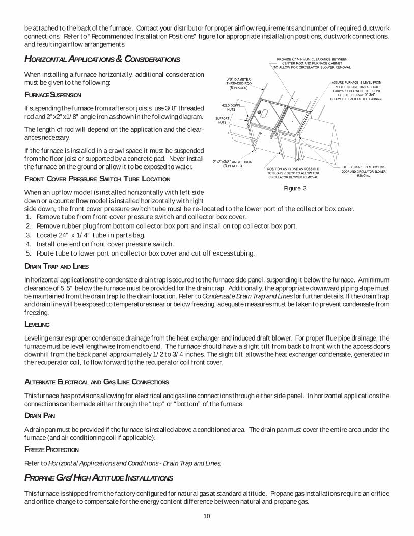
FURNACE SUSPENSION
If suspending the furnace from rafters or joists, use 3/8" threadedrod and 2”x2”x1/8” angle iron as shown in the following diagram.
The length of rod will depend on the application and the clear-ances necessary.
If the furnace is installed in a crawl space it must be suspendedfrom the floor joist or supported by a concrete pad. Never installthe furnace on the ground or allow it to be exposed to water.
FRONT COVER PRESSURE SWITCH TUBE LOCATION
When an upflow model is installed horizontally with left sidedown or a counterflow model is installed horizontally with rightside down, the front cover pressure switch tube must be re-located to the lower port of the collector box cover.1. Remove tube from front cover pressure switch and collector box cover.2. Remove rubber plug from bottom collector box port and install on top collector box port.3. Locate 24” x 1/4” tube in parts bag.4. Install one end on front cover pressure switch.5. Route tube to lower port on collector box cover and cut off excess tubing.
DRAIN TRAP AND LINES
In horizontal applications the condensate drain trap is secured to the furnace side panel, suspending it below the furnace. A minimumclearance of 5.5” below the furnace must be provided for the drain trap. Additionally, the appropriate downward piping slope mustbe maintained from the drain trap to the drain location. Refer to Condensate Drain Trap and Lines for further details. If the drain trapand drain line will be exposed to temperatures near or below freezing, adequate measures must be taken to prevent condensate fromfreezing.
LEVELING
Leveling ensures proper condensate drainage from the heat exchanger and induced draft blower. For proper flue pipe drainage, thefurnace must be level lengthwise from end to end. The furnace should have a slight tilt from back to front with the access doorsdownhill from the back panel approximately 1/2 to 3/4 inches. The slight tilt allows the heat exchanger condensate, generated inthe recuperator coil, to flow forward to the recuperator coil front cover.
ALTERNATE ELECTRICAL AND GAS LINE CONNECTIONS
This furnace has provisions allowing for electrical and gas line connections through either side panel. In horizontal applications theconnections can be made either through the “top” or “bottom” of the furnace.
DRAIN PAN
A drain pan must be provided if the furnace is installed above a conditioned area. The drain pan must cover the entire area under thefurnace (and air conditioning coil if applicable).
FREEZE PROTECTION
Refer to Horizontal Applications and Conditions - Drain Trap and Lines.
PROPANE GAS/HIGH ALTITUDE INSTALLATIONS
This furnace is shipped from the factory configured for natural gas at standard altitude. Propane gas installations require an orificeand orifice change to compensate for the energy content difference between natural and propane gas.
2" 2" 3/8" ANGLE IRON(3 PLACES)
X X
Figure 3
11
High altitude installations may require both a pressure switch andan orifice/spring change. These changes are necessary to com-pensate for the natural reduction in the density of both the gasfuel and the combustion air at higher altitude.
For installations above 7000 feet, please refer to the furnaceSpecification Sheets for required kit(s).
Contact the distributor for a tabular listing of appropriatemanufacturer’s kits for propane gas and/or high altitude installa-tions. The indicated kits must be used to insure safe and properfurnace operation. All conversions must be performed by a quali-fied installer, or service agency.
VENT/FLUE PIPE & COMBUSTION AIR PIPE
A condensing gas furnace achieves its high level of efficiency byextracting almost all of the heat from the products of combustionand cooling them to the point where condensation takes place.Because of the relatively low flue gas temperature and water con-densation requirements, PVC pipe is used as venting material.
In addition to PVC and ABS pipe and fittings, Innoflue® byCentrotherm Eco Systems and PolyPro® by M&G Duravent arealso approved vent and combustion air materials for installa-tions in the U.S.A. and Canada. Manufacturers Installationinstructions for these products must be followed. These prod-ucts have specific instructions for installing, joining and ter-minating. Do not mix materials or components of one manu-facturer with materials or components of another manufac-turer.
All furnaces are built with 2" vent / intake pipe and connec-tors. For furnaces requiring installation of 3" pipe, the tran-sition from 2" to 3" should be done as close to the furnace aspractically possible.
This furnace must not be connected to Type B, BW, or L vent orvent connector, and must not be vented into any portion of a factory built or masonry chimney except when used as a pathway for PVCas described later in this section. Never common vent this appliance with another appliance or use a vent which is used by a solid fuelappliance. Do not use commercially available “no hub connectors” other than those shipped with this product.
It is the responsibility of the installer to follow the manufacturers’ recommendations and to verify that all vent/flue piping andconnectors are compatible with furnace flue products. Additionally, it is the responsibility of the installer to ensure that all piping andconnections possess adequate structural integrity and support to prevent flue pipe separation, shifting, or sagging during furnaceoperation.
DUAL CERTIFICATION: NON-DIRECT/DIRECT VENT
This furnace is dual certified and may be installed as a non-direct vent (single pipe) or direct vent (dual pipe) appliance. A non-directvent installation requires only a vent/flue pipe, while a direct vent installation requires both a vent/flue pipe and a combustion airintake pipe. Refer to the appropriate section for details concerning piping size, length, number of elbows, furnace connections, andterminations.
MATERIALS AND JOINING METHODS
Two-three-inch nominal diameter PVC Schedule 40 pipe meet-ing ASTM D1785, PVC primer meeting ASTM F656, and PVCsolvent cement meeting ASTM D2564 specifications must beused. Fittings must be DWV type fittings meeting ASTM D2665and ASTM D3311. Carefully follow the manufacturer’s instruc-tions for cutting, cleaning, and solvent cementing of PVC.
WARNING
POSSIBLE PROPERTY DAMAGE, PERSONAL INJURY OR DEATH MAY OCCUR IF THE CORRECT CONVERSION KITS ARE NOT INSTALLED. THE APPROPRIATE KITS MUST BE APPLIED TO ENSURE SAFE AND PROPER FURNACE OPERATION. ALL CONVERSIONS MUST BE PERFORMED BY A QUALIFIED INSTALLER OR SERVICE AGENCY.
TO AVOID BODILY INJURY, FIRE OR EXPLOSION, SOLVENT CEMENTS MUST BE KEPT AWAY FROM ALL IGNITION SOURCES (I.E., SPARKS, OPEN FLAMES, AND EXCESSIVE HEAT) AS THEY ARE COMBUSTIBLE LIQUIDS. AVOID BREATHING CEMENT VAPORS OR CONTACT WITH SKIN AND/OR EYES.
WARNING
FAILURE TO FOLLOW THESE INSTRUCTIONS CAN RESULT IN BODILY INJURY OR DEATH. CAREFULLY READ AND FOLLOW ALL INSTRUCTIONS GIVEN IN THIS SECTION.
WARNING
UPON COMPLETION OF THE FURNACE INSTALLATION, CAREFULLY INSPECT THE ENTIRE FLUE SYSTEM BOTH INSIDE AND OUTSIDE OF THE FURNACE TO ASSURE IT IS PROPERLY SEALED. LEAKS IN THE FLUE SYSTEM CAN RESULT IN SERIOUS PERSONAL INJURY OR DEATH DUE TO EXPOSURE TO FLUE PRODUCTS, INCLUDING CARBON MONOXIDE.
Gas Altitude Kit OrificeManifold Pressure Pressure
SwitchChange
0-7000
1 LPM-07* supports both Honeywell and White-Rodgers 1-stage valvesNOTE: In Canada, gas furnaces are only certified to 4500 feet.
12
The use of Schedule 40 PVC or ABS cellular core (Foam Core) plastic pipe is also acceptable as a flue/vent and intake pipematerial. PVC primer meeting ASTM F656 and PVC solvent cement meeting ASTM D2564 specifications must be used.Fittings must be DWV type fittings meeting ASTM D2665 and ASTM D3311. Carefully follow the manufactures instructions forcutting, cleaning and solvent cementing of PVC.
For Canadian installations; all PVC pipe, fittings and joining materials must be UL S636 listed.
As an alternative to PVC pipe, primer, solvent cement, and fittings, ABS materials which are in compliance with the followingspecifications may be used. Two-or-three-inch ABS Schedule 40 pipe must meet ASTM D1527 and, if used in Canada, must be CSAlisted. Solvent cement for ABS to ABS joints must meet ASTM D2235 and, if used in Canada, must be CSA listed. The solvent cementfor the PVC to ABS transition joint must meet ASTM D3138. Fittings must be DWV type fittings meeting ASTM D2661 and ASTM D3311and, if used in Canada, must be CSA listed. Carefully follow the manufacturers’ instructions for cutting, cleaning, and solventcementing PVC and/or ABS.
All 90° elbows must be medium radius (1/4 bend DWV) or long radius (Long sweep 1/4 bend DWV) types conforming to ASTM D3311.A medium radius (1/4 bend DWV) elbow measures 3 1/16” minimum from the plane of one opening to the center line of the otheropening for 2” diameter pipe, and 4 9/16” minimum for 3” pipe.
PROPER VENT/FLUE AND COMBUSTION AIR PIPING PRACTICES
Adhere to these instructions to ensure safe and proper furnace performance. The length, diameter, and number of elbows of thevent/flue pipe and combustion air pipe (when applicable) affects the performance of the furnace and must be carefully sized. Allpiping must be installed in accordance with local codes and these instructions.
Some models require the use of 3” pipe. Do not transition from a 2” to 3” pipe in a horizontal section of pipe as this maycreate a water trap.
PREFERRED
TRANSITION NO LESS THAN 45 DEGREES TO HORIZONTAL PLANE TO AVOID CREATING A WATER TRAP IN VENT PIPING.
ACCEPTABLE
NO TRANSITION ON HORIZONTAL PLANE, THIS CREATES A WATER TRAP AND RESTRICTS FLUE GASES
Figure 4 Figure 5 Figure 6
Piping must be adequately secured and supported to prohibit sagging, joint separation, and/or detachment from the furnace.Horizontal runs of vent/flue piping must be supported every three to five feet and must maintain a 1/4 inch per foot downward slope,back towards the furnace, to properly return condensate to the furnace’s drain system. Allowances should be made for minorexpansion and contraction due to temperature variations. For this reason, particular care must be taken to secure piping when a longrun is followed by a short offset of less than 40 inches.
Precautions should be taken to prevent condensate from freezing inside the vent/flue pipe and/or at the vent/flue pipe termination.All vent/flue piping exposed to freezing temperatures below 35°F for extended periods of time must be insulated with 1/2” thickclosed cell foam. Also all vent/flue piping exposed outdoors in excess of the terminations shown in this manual (or in unheated areas)must be insulated with 1/2” thick closed cell foam. Inspect piping for leaks prior to installing insulation.
TERMINATION LOCATIONS
NOTE: Refer to Location Requirements and Considerations for combustion air contaminant restrictions.
The following bullets and diagram describe the restrictions concerning the appropriate location of vent/flue pipe and combustion airintake pipe (when applicable) terminations. Refer to Non-Direct Vent (Single Pipe) Piping and Direct Vent (Dual Pipe) Piping locatedin this section for specific details on termination construction.
• All terminations (flue and/or intake) must be located at least 12 inches above ground level or the anticipated snow level.• Vent terminations (non-direct and direct vent) must terminate at least 3 feet above any forced air inlet located within 10
feet.NOTE: This provision does not apply to the combustion air intake termination of a direct vent application.
13
• The vent termination of a non-direct vent application mustterminate at least 4 feet below, 4 feet horizontally from, or 1foot above any door, window, or gravity air inlet into anybuilding.
• The vent termination of a direct vent application mustterminate at least 12 inches from any opening through whichflue gases may enter a building (door, window, or gravity airinlet).
• The vent termination of vent pipe run vertically through aroof must terminate at least 12 inches above the roof line (orthe anticipated snow level) and be at least 12 inches fromany vertical wall (including any anticipated snow build up).
• A vent termination shall not terminate over public walkwaysor over an area where condensate or vapor could create anuisance or hazard or could be detrimental to the operationof regulators, relief valves, or other equipment.
• The combustion air intake termination of a direct ventapplication should not terminate in an area which is frequentlydusty or dirty.
NOTE: In Canada, the Canadian Fuel Gas Code takes precedence over the preceding termination restrictions.CANADIAN VENTING REQUIREMENTS
In Canada, venting must conform to the requirements of the current CAN/CSA-B149.1-05 Installation Code. Use only CSA-listed, ULC-S636 compliant two- or three-inch diameter PVC or ABS pipe, solvent cement, and fittings throughout. The certified piping should beclearly marked with the ULC Std “S636” on the pipe and fittings. Carefully follow the pipe manufacturers’ instructions for cutting,cleaning, and solvent cementing PVC and/or ABS.
The vent can be run through an existing unused chimney provided the space between the vent pipe and the chimney is insulated andclosed with a weather-tight, corrosion-resistant flashing.
STANDARD FURNACE CONNECTIONS
It is the responsibility of the installer to ensure that the piping connections to the furnace are secure, airtight, and adequatelysupported.
Vent/Flue Pipe
The vent pipe outlet is sized to accept 2” pipe. Secure vent/flue pipe directly intothe furnace fitting with the appropriate glue. Alternately, a small section of 2" pipemay be glued in the furnace socket and a rubber coupling installed to allow removalfor future service. Combustion Air and Vent piping should be routed in a manner toavoid contact with refrigerant lines, metering devices, condensate drain lines, etc.If necessary, clearances may be increased by creating an offset using two 45 degreeelbows. This joint can be rotated on the fitting to establish maximum clearancebetween refrigerant lines, metering devices, and condensate drain lines, etc. Thisjoint is the equivalent of one 90 deg. elbow when considering elbow count.
NOTE: For non-direct vent installations, a minimum of one90° elbow should be installed on the combustion air intakecoupling to guard against inadvertent blockage.
DIRECT VENT INSTALLATIONS
On upflow units secure the combustion air intake pipe directly to the air intakecoupling. On counterflow units secure the combustion air intake pipe to the air intake coupling using the rubber couplingand worm gear hose clamps provided with the unit. The counterflow rubber coupling allows service removal of air intakepiping internal to the furnace blower compartment. The combustion air intake pipe can also be secured directly to thecounterflow unit air intake pipe coupling.
45 DEGREEELBOWS
Increased Clearance ConfigurationFigure 8
Vent Termination ClearancesFigure 7
12"
Non-Direct VentVent/Flue Termination
No Terminations Above Walkway
12"min.
4'min.
Non-Direct VentVent/Flue Termination
Direct VentVent/Flue Termination
<10'
Forced AirInlet
Non-Direct Vent&
Direct VentVent/Flue Terminations
Grade or Highest Anticipated Snow Level
3' min.
12" min.
4' min.
12" min.
14
NON-DIRECT VENT INSTALLATIONS
A minimum of one 90° elbow should be installed on the combus-tion air intake “coupling” to guard against inadvertent blockage.
ALTERNATE VENT/FLUE LOCATION
The alternate vent/flue location is the large hole directly in line withthe induced draft blower outlet. To use the alternate vent/flue loca-tion refer to the following steps and the “Alternate Vent/Flue Loca-tion” figure. To use an alternate vent location on a counterflow/ horizontal model, a special kit is required.
NOTE: In the horizontal left installation position, a means ofcondensate collection must be provided to keep vent pipe con-densate from entering the draft inducer housing. If the ventdrain elbow is eliminated from the installation, an RF000142 kitmust be used.
1. Remove the four screws from the vent pipe flange on topthe furnace.
2. Remove the internal elbow and vent pipe3. Cut 2 1/2" from the flange .4. Remove plastic plug in line with the inducer outlet5. Install cut end of the flanged section and connect to inducer
with rubber coupling supplied with furnace.6. Install screws removed in step 1 securing flange to cabinet.
THE RUBBER ELBOW IS NOT DESIGNED TO SUPPORT A LOAD. WHEN THE RUBBER ELBOW IS MOUNTED EXTERNALLY TO THE FURNACE CABINET, EXTREME CARE MUST BE TAKEN TO ADEQUATELY SUPPORT FIELD-SUPPLIED VENT/FLUE PIPING, AS DAMAGE CAN RESULT IN LEAKS CAUSING BODILY INJURY OR DEATH DUE TO EXPOSURE TO FLUE GASES, INCLUDING CARBON MONOXIDE
WARNING
ALTERNATE COMBUSTION AIR PROVISION
(Upflow / Horizontal models only)When using the alternate venting location, either in a hori-zontal left side down installation or a vertical installation us-ing down – venting, an alternate combustion air opening canbe used. A locating dimple is located on the right side of thefurnace cabinet. The locating dimple is 1 7/8" measured fromthe front edge of the cabinet in line with the knock out. Touse the alternate combustion air location:1. Remove screws and combustion air flange from cabinet.2. Insert cabinet plug in unused combustion air hole.3. Drill a pilot hole at the cabinet dimple (size dictated by
knockout tool used).4. Use a knockout tool to create a 3" diameter hole5. Install combustion air flange and secure with screws
removed in step one.
EDGES OF SHEET METAL HOLES MAY BE SHARP. USE GLOVES AS A PRECAUTION WHEN REMOVING HOLE PLUGS.
WARNING
CU
T H
ER
E
Figure 10
Vent/Flue Pipe Cuts
Insert flange. Cut 2 ½” long.
R 000142F
Figure 9
BE SURE NOT TO DAMAGE INTERNAL WIRING OR OTHER COMPONENTS WHEN REINSTALLING COUPLING AND SCREWS.
CAUTION
THE RUBBER ELBOW IS NOT DESIGNED TO SUPPORT A LOAD. WHEN THE RUBBER ELBOW IS MOUNTED EXTERNALLY TO THE FURNACE CABINET, EXTREME CARE MUST BE TAKEN TO ADEQUATELY SUPPORT FIELD-SUPPLIED VENT/FLUE PIPING, AS DAMAGE CAN RESULT IN LEAKS CAUSING BODILY INJURY OR DEATH DUE TO EXPOSURE TO FLUE GASES, INCLUDING CARBON MONOXIDE
WARNING
15
NON-DIRECT VENT (SINGLE PIPE) PIPING
Non-direct vent installations require only a vent/flue pipe. The vent pipe can be run horizontally with an exit through the side of thebuilding or run vertically with an exit through the roof of the building. The vent can also be run through an existing unused chimney;however, it must extend a minimum of 12 inches above the top of the chimney. The space between the vent pipe and the chimneymust be closed with a weather-tight, corrosion-resistant flashing.
Although non-direct vent installations do not require a combustion air intake pipe, a minimum of one 90° elbow should be attachedto the furnace’s combustion air intake if: an upright installation uses the standard intake location, or a horizontal installation uses thealternate air intake location. This elbow will guard againstinadvertent blockage of the air intake.
VENT/FLUE PIPE LENGTHS AND DIAMETERS
NOTE: If either a 90 degree or 45 degree elbow is used fortermination, it must be pointed downward.
Refer to the Direct and Non-Direct Vent Table for applicablelength, elbows, and pipe diameter for construction of the vent/flue pipe system of a non-direct vent installation. In additionto the vent/flue pipe, a single 90° elbow should be secured tothe combustion air intake to prevent inadvertent blockage. Thetee used in the vent/flue termination must be included whendetermining the number of elbows in the piping system.
VENT/FLUE PIPE TERMINATIONS
NOTE: If either a 90 degree or 45 degree elbow is used fortermination, it must be pointed downward.
The vent/flue pipe may terminate vertically, as through a roof,or horizontally, as through an outside wall.
Vertical vent/flue pipe terminations should be as shown in thefollowing figure. Refer to Vent/Flue Pipe and Combustion AirPipe - Termination Locations for details concerning location re-strictions. The penetration of the vent through the roof mustbe sealed tight with proper flashing such as is used with a plas-tic plumbing vent.
Horizontal vent/flue pipe terminations should be as shown inthe following figure. Refer to Vent/Flue Pipe and CombustionAir Pipe. To secure the pipe passing through the wall and pro-hibit damage to piping connections, a coupling should be in-stalled on either side of the wall and solvent cemented to alength of pipe connecting the two couplings. The length of pipeshould be the wall thickness plus the depth of the socket fit-tings to be installed on the inside and outside of the wall. Thewall penetration should be sealed with silicone caulkingmaterial.
NOTE: Terminate both pipes in the same pressure zone(same side of roof, no major obstacles between pipes,etc.).
1) Maximum allowable limits listed on individual lengths for inlet and flue and NOTa combination.
2) Minimum requirement for each vent pipe is five (5) feet in length and oneelbow/tee.
3) Tee used in the vent/flue termination must be included when determining thenumber of elbows in the piping system.
4) 2 1/2” or 3” diameter pipe can be used in place of 2” diameter pipe.5) Increased Clearance Configurations using (2) 45 deg. Long Sweep elbows should
be considered equivalent to one 90 deg. elbow.6) One 90° elbow should be secured to the combustion air intake connection.
*MSS9* / *CSS9 Direct Vent (2-Pipe)& Non-Direct Vent (1-Pipe) (6)
Maximum Allowable Length of Vent/FLue Pipe& Combustion Air Pipe (Ft) (1) (2)
ModelPipeSize
1 2 3 4 5 6 7 8
2" 145 140 135 130 125 120 115 110
3" 238 231 224 217 210 203 196 189
2" 220 215 210 205 200 195 190 185
3" 224 217 210 203 196 189 182 175
2" 95 90 85 80 75 70 65 60
3" 238 231 224 217 210 203 196 189
2" 95 90 85 80 75 70 65 60
3" 238 231 224 217 210 203 196 189
2" 45 40 35 30 25 20 15 10
3" 217 210 203 196 189 182 175 168
2" 45 40 35 30 25 20 15 10
3" 217 210 203 196 189 182 175 168
*MSS9*1205DNA* 3" 238 231 224 217 210 203 196 189
Model PipeSize
1 2 3 4 5 6 7 8
2" 145 140 135 130 125 120 115 110
3" 238 231 224 217 210 203 196 189
2" 120 115 110 105 100 95 90 85
3" 224 217 210 203 196 189 182 175
2" 95 90 85 80 75 70 65 60
3" 238 231 224 217 210 203 196 189
2" 25 20 15 10 5 n/a n/a n/a
3" 238 231 224 217 210 203 196 189
*CSS9*1205DNA* 3" 238 231 224 217 210 203 196 189
*MSS9*0805CNA*
*MSS921004CNA**MSS921005CNA**MSS961005CNA*
*CSS9*0402BNA*
*CSS9*0603BNA*
*CSS9*0804CNA*
*CSS9*1005CNA*
Number of Elbows (3) (5)
*MSS9*0402BNA*
*MSS9*0603BNA*
*MSS9*0803BNA*
*MSS9*0804CNA*
16
Floor
Use alternate vent& combination air locations
Field SuppliedDrain Tee on Vent Pipe
DOWN VENTING UPFLOW MODEL FURNACES ONLY
Basement / Crawlspace
Slope 1/4” per foot min.
Condensate trappedto previent flue gas from escaping
Combustion Air Pipe
Vent Pipe
To Field SuppliedCondensate Disposal
All piping and fittings must be joined per material manufacturer’s specifications to prevent separation and flue gas leaks.
The inlet air screens provided in the installation instruction packet are available for the installer to use in the inlet of the combustionair pipe to prevent animals from building nests in the combustion air pipe. Installation of screens, while strongly recommended, isnot required and will not affect performance of the unit.
Direct vent installations require both a combustion air intake and a vent/flue pipe. The pipes may be run horizontally and exitthrough the side of the building or run vertically and exit through the roof of the building. The pipes may be run through an existingunused chimney; however, they must extend a minimum of 12 inches above the top of the chimney. The space between the pipesand the chimney must be closed with a weather tight, corrosion resistant flashing. Both the combustion air intake and a vent/fluepipe terminations must be in the same atmospheric pressure zone. Refer to Vent/Flue and Combustion Air Pipe - TerminationLocations or Concentric Vent Termination for specific details on termination construction. For details concerning connection of pipesto the furnace, refer to the Vent/Flue Pipe and Combustion Pipe - Standard Furnace Connections or Alternate Furnace Connections.
VENT/FLUE & COMBUSTION AIR PIPE LENGTHS & DIAMETERS
Refer to the following table for applicable length, elbows, and pipe diameter for construction of the vent/flue and combustion airintake pipe systems of a direct vent (dual pipe) installation. Thenumber of elbows tabulated represents the number of elbows and/or tees in each (Vent/Flue & Combustion Air Intake) pipe. Elbowsand/or tees used in the terminations must be included when de-termining the number of elbows in the piping systems.
If the combustion air intake pipe is to be installed above a finishedceiling or other area where dripping of condensate will be objec-tionable, insulation of the combustion air pipe may be required.
Use 1/2” thick closed cell foam insulation such as Armaflex™or Insultube™ where required.
VENT/FLUE AND COMBUSTION AIR PIPE TERMINATIONS
The vent/flue and combustion air pipes may terminate vertically,as through a roof, or horizontally, as through an outside wall.
Vertical pipe terminations should be as shown in the following fig-ure. Refer to Vent/Flue Pipe and Combustion Pipe - TerminationLocations for details concerning location restrictions. Thepenetrations through the roof must be sealed tight with properflashing such as is used with a plastic plumbing vent.
Vent & Combustion Air Intake Measurements for Stan-dard Horizontal Terminations (Dual Pipe)
Center to center = 10” min / 24” max.Vertical separation: 0” - 24”Vent termination from wall = 8” min / 12” max.Combustion air intake from wall = 6” max.Vent and intake clearance to ground or anticipated snowlevel = 12” min.
VENT/INTAKE TERMINATIONS FOR INSTALLATION OF MULTIPLE
DIRECT VENT FURNACES
If more than one direct vent furnace is to be installed verti-cally through a common roof top, maintain the same mini-mum clearances between the exhaust vent and air intaketerminations of adjacent units as with the exhaust vent andair intake terminations of a single unit.
90º OR 45°ELBOW
SCREEN(OPTIONAL)
12" MIN. TO GRADE ORHIGHEST ANTICIPATED
SNOW LEVEL
6” MAX
10”- 24”
4” MIN
Standard Horizontal Terminations (Dual Pipe)Figure 15
12” MIN TO GRADE OR HIGHEST ANTICIPATED SNOW LEVEL
12” MIN SEPARATION
3”MIN24”MAX
OPTIONALINTAKESCREENS
Termination of Multiple Direct Vent FurnacesFigure 18
If more than one direct vent furnace is to be installed horizontally through a common side wall, maintain the clearances as in thefollowing figure. Always terminate all exhaust vent outlets at the same elevation and always terminate all air intakes at the sameelevation.
CONCENTRIC VENT TERMINATION
Refer to the directions provided with the Concentric Vent Kit (DCVK) for installation specifications.
SIDE WALL VENT KIT
This kit is to be used with 2” or 3” direct vent systems. Thevent kit must terminate outside the structure and may be in-stalled with the intake and exhaust pipes located side-by-side orwith one pipe above the other. These kits are NOT intended foruse with single pipe (non-direct vent) installations.
Refer to the directions furnished with the Side Wall Vent Kit(p/n 0170K00000S or 0170K000001S) for installation speci-fications.
CONDENSATE DRAIN LINES & DRAIN TRAP
A condensing gas furnace achieves its high level of efficiency by extracting heat from the products of combustion to the point wherecondensation takes place. The condensate must be collected in the furnace drain trap and routed to an appropriate drainlocation in compliance with local and national codes.
Follow the bullets listed below when installing the drain system. Refer to the following sections for specific details concerning furnacedrain trap installation and drain hose hook ups.
• The drain trap supplied with the furnace must be used.• The drain trap must be primed at time of installation.• The drain line between furnace and drain location must meet local and nation codes.
SCREEN(OPTIONAL)
AIRINTAKE
90°ELBOWS
12" MIN. ABOVEHIGHEST ANTICIPATED
SNOW LEVEL
3”-24” BETWEEN PIPES
Combustion Air Intake may also be snorkeled to obtain 12” minground clearance.
• The drain line between furnace and drain location must maintain a 1/4 inch per foot downward slope toward the drain.• Do not trap the drain line in any other location than at the drain trap supplied with the furnace.• If the drain line is routed through an area which may see temperatures near or below freezing, precautions must be
taken to prevent condensate from freezing within the drain line.• If an air conditioning coil is installed with the furnace, a common drain may be used. An open tee must be installed in
the drain line, near the cooling coil, to relieve positive air pressure from the coil’s plenum. This is necessary to prohibitany interference with the function of the furnace’s drain trap.
NOTE: In vertical installations, air conditioning coil condensate may drain into the furnace trap as long as there is a trapbetween the coil and the furnace trap and the drain pipe is not terminating below the water level of the furnace trap.
GENERAL DRAIN INFORMATION
All furnace models come with a factory installed drain trap. For vertical installations, the trap will remain in the factoryposition except for a counterflow when the installer desires the drain to exit the right side. All furnace models installedhorizontally require the trap to be relocated. Many drain hoses havea built–in grommet which will provide a cabinet seal when installed.See instructions below for your model and installation position.NOTE: Both sides of the drain trap must be primed prior toinitial furnace start up
FIELD SUPPLIED DRAIN
Drain the furnace and air conditioning coil if applicable, in compli-ance with code requirements. In horizontal or counterflow installa-tions, a field installed rubber coupling will allow the drain trap to beremoved for cleaning. The drain trap must be primed before initialfurnace start up. When an air conditioning coil drain is connectedto the field supplied furnace drain, it must be vented.
#3
#1#2
#4#5
#6
#7#8
#9
#10
#11100 DegreeElbow
Coupling
Figure 20
NOTE: Hoses are model specificand not all hoses will be shipped with all models.
20
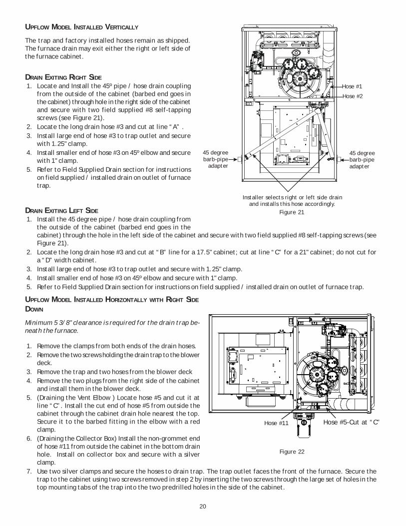
UPFLOW MODEL INSTALLED VERTICALLY
The trap and factory installed hoses remain as shipped.The furnace drain may exit either the right or left side ofthe furnace cabinet.
DRAIN EXITING RIGHT SIDE1. Locate and Install the 45º pipe / hose drain coupling
from the outside of the cabinet (barbed end goes inthe cabinet) through hole in the right side of the cabinetand secure with two field supplied #8 self-tappingscrews (see Figure 21).
2. Locate the long drain hose #3 and cut at line “A” .3. Install large end of hose #3 to trap outlet and secure
with 1.25" clamp.4. Install smaller end of hose #3 on 45º elbow and secure
with 1" clamp.5. Refer to Field Supplied Drain section for instructions
on field supplied / installed drain on outlet of furnacetrap.
DRAIN EXITING LEFT SIDE1. Install the 45 degree pipe / hose drain coupling from
the outside of the cabinet (barbed end goes in thecabinet) through the hole in the left side of the cabinet and secure with two field supplied #8 self-tapping screws (seeFigure 21).
2. Locate the long drain hose #3 and cut at “B” line for a 17.5" cabinet; cut at line “C” for a 21" cabinet; do not cut fora “D” width cabinet.
3. Install large end of hose #3 to trap outlet and secure with 1.25" clamp.4. Install smaller end of hose #3 on 45º elbow and secure with 1" clamp.5. Refer to Field Supplied Drain section for instructions on field supplied / installed drain on outlet of furnace trap.
UPFLOW MODEL INSTALLED HORIZONTALLY WITH RIGHT SIDE
DOWN
Minimum 5 3/8" clearance is required for the drain trap be-neath the furnace.
1. Remove the clamps from both ends of the drain hoses.2. Remove the two screws holding the drain trap to the blower
deck.3. Remove the trap and two hoses from the blower deck4. Remove the two plugs from the right side of the cabinet
and install them in the blower deck.5. (Draining the Vent Elbow ) Locate hose #5 and cut it at
line “C”. Install the cut end of hose #5 from outside thecabinet through the cabinet drain hole nearest the top.Secure it to the barbed fitting in the elbow with a redclamp.
6. (Draining the Collector Box) Install the non-grommet endof hose #11 from outside the cabinet in the bottom drainhole. Install on collector box and secure with a silverclamp.
7. Use two silver clamps and secure the hoses to drain trap. The trap outlet faces the front of the furnace. Secure thetrap to the cabinet using two screws removed in step 2 by inserting the two screws through the large set of holes in thetop mounting tabs of the trap into the two predrilled holes in the side of the cabinet.
Installer selects right or left side drainand installs this hose accordingly.
Hose #1
Hose #2
45 degreebarb-pipeadapter
45 degreebarb-pipe
adapter
Figure 21
Figure 22
Hose #11 Hose #5-Cut at “C”
21
8. Refer to Field Supplied Drain section for instructions onfield supplied / installed drain on outlet of furnace trap.
UPFLOW MODEL INSTALLED HORIZONTALLY WITH LEFT SIDE
DOWN
Minimum 5 3/8" clearance is required for the drain trap be-neath the furnace.
1. Remove the clamps from the two drain tubes on the trap.2. Remove the two screws holding the drain trap to the blower
deck.3. Remove the trap and hoses from the blower deck .4. Remove the two plugs from the left side of the cabinet
and install them in the blower deck.5. (Draining the Vent Elbow) Locate hose #6. Measuring from
the non-grommet end; cut off and discard 1 ½” for a “D”width cabinet, 5” for a “C” width cabinet, 8 ½” for a “B”width cabinet.
6. Remove the rubber plug from vent – drain elbow side port. Place hose #6 on the vent – drain elbow side port and securewith a silver clamp .
7. Place cap on vent – drain elbow barb fitting and secure with red clamp8. Locate hose #5 and cut 3” from the non-grommet end. Discard the section without the grommet.9. Insert the cut end of tube #5 through the lower cabinet drain hole.10.Connect hose #6 & hose #5 using 100º elbow and secure with two red clamps11. (Draining the Collector Box) Install the non-grommet end of hose #11 from outside the cabinet in the bottom drain hole.
Install on collector box and secure with a silver clamp.12.Use two silver clamps and secure the hoses to drain trap. The trap outlet faces the front of the furnace. Secure the trap
to the cabinet using two screws removed in step 2 by inserting the two screws through the large set of holes in the topmounting tabs of the trap into the two predrilled holes in the side of the cabinet.
13.Place cap on vent – drain elbow barb fitting and secure with red clamp.14.Refer to Field Supplied Drain section for instructions on field supplied / installed
drain on outlet of furnace trap.
COUNTERFLOW MODEL INSTALLED VERTICALLY
The furnace drain may exit the right or left side of the furnace cabinet (left side pre-ferred) Trap and factory installed hoses remain as shipped if the drain will exit the leftside of the cabinet. Draining from the right side requires relocation of the trap tooutside the cabinet.
DRAIN EXITING LEFT SIDE1. Install a field supplied rubber coupling secured with a 1 1/4” clamp to enable removing
the trap for future cleaning. Alternately, a PVC fitting may be glued on the trapoutlet.
2. Install drain per local and National codes.
Hose #6Hose #5 Hose #11
Figure 23
Hose #5 x 2 Hose #4 x 2
Figure 24
22
DRAIN EXITING RIGHT SIDE
1. Remove hose clamps and hoses from trap.2. Remove trap.3. (Draining the Vent Elbow) Insert the non-grommet
end hose #10 into the cabinet back drain hole. Secure onvent – drain elbow barb fitting with a red clamp.
4. Insert 100º elbow into the cut end and secure with redclamp.
5. (Draining the Collector Box) Insert non-grommet end ofhose #9 into thecabinet front drain hole and secure on collector box drainport with a silver clamp.
6. Mate the drain trap inlets to the hoses and secure withsilver clamps.
7. Line up the trap mounting holes with the pre-drilled holesin the furnace and secure with 2 screws removed in step2.
8. Refer to Field Supplied Drain section for instructions on field supplied / installed drain on outlet of furnace trap.
COUNTERFLOW MODEL INSTALLED HORIZONTALLY WITH RIGHT
SIDE DOWN
Minimum 5 3/8" clearance is required for the drain trap beneaththe furnace.
1. Remove hose clamps and hoses from trap.2. Remove trap.3. (Draining the Collector Box) From outside the cabinet, insert
the non-grommet end hose #8 into the back drain hole.4. Secure to collector box drain port using a silver clamp.5. (Draining the Vent Elbow) From outside the cabinet, insert
the non-grommet end of hose #7 into the front cabinet drainhole and secure on the vent – drain elbow barb fitting using ared clamp
6. Mate the trap inlets to the hoses, the outlet of the trap mustface the original bottom of the furnace. Secure with silverclamps.
7. Fasten the drain trap to the cabinet with two screws removedin step 2
8. Refer to Field Supplied Drain section for instructions on fieldsupplied / installed drain on outlet of furnace trap.
COUNTERFLOW MODEL INSTALLED HORIZONTALLY WITH LEFT
SIDE DOWN
Minimum 5 3/8" clearance is required for the drain trap beneaththe furnace.
1. Remove hose clamps and hoses from trap.2. Remove trap.3. Remove plugs from left side of cabinet and install in blower
deck.4. (Draining the Collector Box) Locate hose #4 and place the
radius end on the collector box drain port, secure with asilver clamp.
Figure 25
Drain Port
Hose #7Hose #8
Figure 26
Hose #4
Hose #5 x2Hose #4
Figure 27
23
5. Locate hose #2, insert from outside the cabinet in the drain hole closest to the front of the cabinet, insert a coupling andsecure with a red clamp.
6. Mate coupling to hose #4 and secure with a red clamp.7. (Draining the Vent Elbow) Remove plug from vent – drain elbow side port.8. Locate hose #4 and place radius end on the side port of vent – drain elbow and secure with a red clamp.9. Install cap on vent drain elbow barb fitting and secure with red clamp.10. Insert PVC pipe into hose #4 and secure with a red clamp.11. Locate hose #5, insert it from outside the cabinet in the drain hole farthest from the front of the cabinet.12. Insert 100º elbow in hose #5 and secure with a red clamp.13. Locate another hose #5 cut a 5.25" straight section and discard the radius end.14. Connect the 5.25’ straight section to the 100º elbow and the PVC pipe and secure with red clamps.15. Mate trap inlets and hoses and secure with silver clamps, drain trap outlet must point to the original bottom of the
furnace.16. Secure trap to furnace using two screws removed in step 2.17. Refer to Field Supplied Drain section for instructions on field supplied / installed drain on outlet of furnace trap.
ELECTRICAL CONNECTIONS
WIRING HARNESS
The wiring harness is an integral part of this furnace. Wires arecolor coded for identification purposes. Refer to the wiring dia-gram for wire routings. If any of the original wire as suppliedwith the furnace must be replaced, it must be replaced withwiring material having a temperature rating of at least 105° C.Any replacement wiring must be a copper conductor.
115 VOLT LINE CONNECTIONS
Before proceeding with electrical connections, ensure that thesupply voltage, frequency, and phase correspond to that speci-fied on the unit rating plate. Power supply to the furnace mustbe NEC Class 1, and must comply with all applicable codes. Thefurnace must be electrically grounded in accordance with localcodes or, in their absence, with the latest edition of The NationalElectric Code, ANSI NFPA 70 and/or The Canadian Electric CodeCSA C22.1.
Use a separate fused branch electrical circuit containing properlysized wire, and fuse or circuit breaker. The fuse or circuit breakermust be sized in accordance with the maximum overcurrent pro-tection specified on the unit rating plate. An electrical disconnect must be provided at the furnace location.
Connect hot, neutral, and ground wires as shown in the wiring diagram located on the unit’s blower door. For direct ventapplications, the cabinet opening to the junction box must be sealed air tight using either an UL approved bushing such as HeycoLiquid Tight or by applying non-reactive UL approved sealant to bushing.
Line polarity must be observed when making field connections. Line voltage connections can be made through either the right orleft side panel. The furnace is shipped configured for a right side (left side for counterflows) electrical connection with thejunction box located inside the burner compartment. To make electrical connections through the opposite side of the furnace, thejunction box must be relocated to the other side of the burner compartment prior to making electrical connections. To relocate thejunction box, follow the steps shown below.
NOTE: Wire routing must not to interfere with circulator blower operation, filter removal, or routine maintenance.
HIGH VOLTAGE !TO AVOID THE RISK OF ELECTRICAL SHOCK, WIRING TO THE UNIT MUST BE POLARIZED AND GROUNDED.
WARNING
HIGH VOLTAGE !TO AVOID PERSONAL INJURY OR DEATH DUE TO ELECTRICAL SHOCK, DISCONNECT ELECTRICAL POWER BEFORE SERVICING OR CHANGING ANY ELECTRICAL WIRING.
WARNING
LABEL ALL WIRES PRIOR TO DISCONNECTION WHEN SERVICING CONTROLS. WIRING ERRORS CAN CAUSE IMPROPER AND DANGEROUS OPERATION. VERIFY PROPER OPERATION AFTER SERVICING.
CAUTION
24
EDGES OF SHEET METAL HOLES MAY BE SHARP. USE GLOVES AS A PRECAUTION WHEN REMOVING HOLE PLUGS.
WARNING
TO PREVENT PERSONAL INJURY OR DEATH DUE TO ELECTRIC SHOCK, DISCONNECT ELECTRICAL POWER BEFORE INSTALLING OR SERVICING THIS UNIT.
WARNING
HIGH VOLTAGE !TO AVOID THE RISK OF INJURY, ELECTRICAL SHOCK OR DEATH, THE FURNACE MUST BE ELECTRICALLY GROUNDED IN ACCORDANCE WITH LOCAL CODES OR IN THEIR ABSENCE, WITH THE LATEST EDITION OF THE NATIONAL ELECTRIC CODE.
WARNING
JUNCTION BOX RELOCATION
Line voltage connections can be made through either the rightor left side panel. The furnace is shipped configured for aright side electrical connection. To make electrical connec-tions through the opposite side of the furnace, the junctionbox must be relocated to the left side prior to making electri-cal connections. To relocate the junction box, perform thefollowing steps.
1. Remove the burner compartment door.2. Remove and save the two screws securing the junction box
to the side panel.3. Relocate junction box and associated plugs and grommets
to opposite side panel. Secure with screws removed in step2.
To ensure proper unit grounding, the ground wire should runfrom the furnace ground screw located inside the furnace junc-tion box all the way back to the electrical panel. NOTE: Do notuse gas piping as an electrical ground. To confirm proper unitgrounding, turn off the electrical power and perform the followingcheck.
1. Measure resistance between the neutral (white) connectionand one of the burners.
2. Resistance should measure 10 ohms or less.
This furnace is equipped with a blower door interlock switch whichinterrupts unit voltage when the blower door is opened for servic-ing. Do not defeat this switch.
24 VOLT THERMOSTAT WIRING
Low voltage connections can be made through either the right orleft side panel. Thermostat wiring entrance holes are located inthe blower compartment. The following figure shows connectionsfor a “heat/cool system”.
This furnace is equipped with a 40 VA transformer to facilitate usewith most cooling equipment. Consult the wiring diagram, locatedon the blower compartment door, for further details of 115 Volt and24 Volt wiring.
SINGLE-STAGE HEATING THERMOSTAT APPLICATION
A single-stage thermostat with only one heating stage is neededto control this furnace.
WIRE ROUTING MUST NOT INTERFERE WITH CIRCULATOR BLOWER OPERATION, FILTER REMOVAL OR ROUTINE MAINTENANCE.
IMPORTANT NOTE
Figure 28
R
Y C
Furnace IntegratedControl Module
Remote Condensing Unit(Single-Stage Cooling)
R
RoomThermostat
WARNING
TO AVOID THE RISK OF INJURY, ELECTRICAL SHOCK OR DEATH, THE FURNACE MUST BE ELECTRICALLY GROUNDED IN ACCORDANCE WITH LOCAL CODES OR, IN THEIR ABSENCE, WITH THE LATEST EDITION OF THE NATIONAL ELECTRICAL CODE.
25
FOSSIL FUEL APPLICATIONS
This furnace can be used in conjunction with a heat pump in a fossilfuel application. A fossil fuel application refers to a combined gasfurnace and heat pump installation which uses an outdoor tem-perature sensor to determine the most cost efficient means ofheating (heat pump or gas furnace).
Strictly follow the wiring guidelines in the fossil fuel kit installationinstructions. All furnace connections must be made to the furnacetwo-stage integrated control module and the “FURNACE” terminal strip on the fossil fuel control board.
GAS SUPPLY AND PIPING
The furnace rating plate includes the approved furnace gas inputrating and gas types. The furnace must be equipped to operate onthe type of gas applied. This includes any conversion kits requiredfor alternate fuels and/or high altitude.
Inlet gas supply pressures must be maintained within the rangesspecified in the following table. The supply pressure must be constant and available with all other household gas fired appliancesoperating. The minimum gas supply pressure must be maintained to prevent unreliable ignition. The maximum must not beexceeded to prevent unit overfiring.
HIGH ALTITUDE DERATE
When this furnace is installed at high altitude, the appropriate High Altitude orifice kit must be applied. This is required due to thenatural reduction in the density of both the gas fuel and combustion air as altitude increases. The kit will provide the proper designcertified input rate within the specified altitude range.
High altitude kits are purchased according to the installation altitude and usage of either natural or propane gas. Consult thefurnace Specification Sheet for appropriate kits.
Do not derate the furnace by adjusting the manifold pressure to a lower pressure than specified on the furnace rating plate. Thecombination of the lower air density and a lower manifold pressure will prohibit the burner orifice from drawing the proper amount ofair into the burner. This may cause incomplete combustion, flashback, and possible yellow tipping.
In some areas the gas supplier may artificially derate the gas in an effort to compensate for the effects of altitude. If the gas isartificially derated, the appropriate orifice size must be determined based upon the BTU/ft3 content of the derated gas and thealtitude. Refer to the National Fuel Gas Code, NFPA 54/ANSI Z223.1, and information provided by the gas supplier to determine theproper orifice size.
A different pressure switch may be required at high altitude regardless of the BTU/ft3 content of the fuel used. Consult the furnaceSpecification Sheet for pressure switch.
PROPANE GAS CONVERSION
This unit is configured for natural gas. To operate this furnaceon L.P. gas, an LPM-07 LP Conversion kit must be used.
The indicated kit must be used to insure safe and proper furnaceoperation. All conversions must be performed by a qualified in-staller, or service agency.
GAS VALVE
This unit is equipped with a 24 volt gas valve controlled during furnace operation by the integrated control module. As shipped, thevalve is configured for natural gas. The valve is field convertible for use with propane gas by replacing the regulator spring with apropane gas spring from an appropriate manufacturer’s propane gas conversion kit. Taps for measuring the gas supply pressure andmanifold pressure are provided on the valve.
The gas valve has a manual ON/OFF control located on the valve itself. This control may be set only to the “ON” or “OFF” position.Refer to the lighting instructions label or Startup Procedure & Adjustment for use of this control during start up and shut downperiods.
TO PREVENT UNRELIABLE OPERATION OR EQUIPMENT DAMAGE, THE GAS MANIFOLD PRESSURE MUST BE AS SPECIFIED ON THE UNIT RATING PLATE. ONLY MINOR ADJUSTMENTS SHOULD BE MADE BY ADJUSTING THE GAS VALVE PRESSURE REGULATOR.
CAUTION
HIGH VOLTAGE !TO AVOID PERSONAL INJURY OR DEATH DUE TO ELECTRICAL SHOCK, DISCONNECT ELECTRICAL POWER BEFORE SERVICING OR CHANGING ANY ELECTRICAL WIRING.
WARNING
WARNING
POSSIBLE PROPERTY DAMAGE, PERSONAL INJURY OR DEATH MAY OCCUR IF THE CORRECT CONVERSION KITS ARE NOT INSTALLED. THE APPROPRIATE KITS MUST BE APPLIED TO ENSURE SAFE AND PROPER FURNACE OPERATION. ALL CONVERSIONS MUST BE PERFORMED BY A QUALIFIED INSTALLER OR SERVICE AGENCY.
26
GAS PIPING CONNECTIONS
The gas piping supplying the furnace must be properly sized basedon the gas flow required, specific gravity of the gas, and length ofthe run. The gas line installation must comply with local codes, orin their absence, with the latest edition of the National Fuel GasCode, NFPA 54/ANSI Z223.1.
To connect the furnace to the building’s gas piping, the installermust supply a ground joint union, drip leg, manual shutoff valve,and line and fittings to connect to gas valve. In some cases, theinstaller may also need to supply a transition piece from 1/2" pipeto a larger pipe size.
The following stipulations apply when connecting gas piping. Referto Gas Piping Connections figure for typical gas line connections tothe furnace.
• Gas piping must be supported external to the furnace cabinetso that the weight of the gas line does not distort the burnerrack, manifold or gas valve.
• Use black iron or steel pipe and fittings for building piping.Where possible, use new pipe that is properly chamfered,reamed, and free of burrs and chips. If old pipe is used, besure it is clean and free of rust, scale, burrs, chips, and old pipejoint compound.
• Use pipe joint compound on male threads ONLY. Always use pipe joint compound (pipe dope) that is APPROVED FOR ALLGASSES. DO NOT apply compound to the first two threads.
• Use ground joint unions.
• Install a drip leg to trap dirt and moisture before it can enter the gas valve. The drip leg must be a minimum of three incheslong.
• Install a 1/8" NPT pipe plug fitting, accessible for test gauge connection, immediately upstream of the gas supply connectionto the furnace.
• Always use a back-up wrench when making the connection to the gas valve to keep it from turning. The orientation of the gasvalve on the manifold must be maintained as shipped from the factory. Maximum torque for the gas valve connection is 375in-lbs; excessive over-tightening may damage the gas valve.
• Install a manual shutoff valve between the gas meter and unit within six feet of the unit. If a union is installed, the union mustbe downstream of the manual shutoff valve, between the shutoff valve and the furnace.
• Tighten all joints securely.
• Connect the furnace to the building piping by one of the following methods:
– Rigid metallic pipe and fittings.
– Semi-rigid metallic tubing and metallic fittings. Aluminum alloy tubing must not be used in exterior locations. In order toseal the grommet cabinet penetration, rigid pipe must be used to reach the outside of the cabinet. A semi-rigid connectorto the gas piping may be used from there.
• Use listed gas appliance connectors in accordance with their instructions. Connectors must be fully in the same room as thefurnace.
• Protect connectors and semirigid tubing against physical and thermal damage when installed. Ensure aluminum-alloy tubingand connectors are coated to protect against external corrosion when in contact with masonry, plaster, or insulation, orsubjected to repeated wetting by liquids such as water(except rain water), detergents, or sewage.
TO AVOID POSSIBLE UNSATISFACTORY OPERATION OF EQUIPMENT DAMAGE DUE TO UNDERFIRING OR EQUIPMENT, USE THE PROPER SIZE OF NATURAL/PROPANE GAS PIPING NEEDED WHEN RUNNING PIPE FROM THE METER/TANK TO THE FURNACE.
WARNING
Natural Gas Capacity of PipeIn Cubic Feet of Gas Per Hour (CFH)
Length of Nominal Black Pipe SizePipe in Feet 1/2" 3/4" 1" 1 1/4" 1 1/2"
(Pressure 0.5 psig or less and pressure drop of 0.3" W.C.; Based on0.60 Specif ic Gravity Gas)
CFH = BTUH Furnace Input Heating Value of Gas (BTU/Cubic Foot)
27
The gas piping may enter the left or right side of the fur-nace cabinet. The installer must supply rigid pipe long enough to reach the outside of the cabinet to seal the grommet cabinetpenetration. A semi-rigid connector to the gas piping can be used outside the cabinet per local codes. 1/2” NPT pipe andfittings are required. For models with an “L” shaped manifold, a 4 1/2” long nipple is required. For models with a hookshaped manifold, a 2” long nipple is required.
A semi-rigid connector to the gas piping can be used outside the cabinet per local codes. From the elbow, the length ofpipe and the fittings required will vary by the side chosen, location of union and cabinet width. The union may be placedinside or outside of the cabinet.
AlternateGas LineLocation
Plug inAlternateGas LineHole
Gas Valve
Burners
Manual Shut Off Valve(upstream from ground joint pipe union)
Drip Leg
Grommetin Standard
Gas LineHole
*GroundJointPipe Union
*GroundJoint
Pipe Union
*NOTE: Union may be inside furnace cabinet where allowed by local codes.
COUNTERFLOWFigure 30
Drip Leg
Plug in Main Gas Line Hole
AlternateUnionLocation
Manual Shut Off Valve (upstream from ground joint pipe union)
GasValve
Burners
Drain Trap
Manifold
Plug in Alternate Gas Line HoleGrommet in
Standard Gas Line Hole
UPFLOW - HORIZONTAL LEFTFigure 31
Manual Shut Off Valve (upstream from ground joint pipe union)
COUNTERFLOW - HORIZONTAL RIGHTFigure 32
Gas Piping Connections
AlternateGas LineLocation
Gas Valve
Burners Manual Shut Off Valve(upstream fromground joint pipe union)
Drip Leg
Grommetin StandardGas LineHole
*GroundJointPipeUnion
*GroundJointPipe
Union
*NOTE: Union may be inside furnace cabinet where allowed by local codes.
Manifold
UPFLOWFigure 29
28
GAS PIPING CHECKS
Before placing unit in operation, leak test the unit and gas connec-tions.
Check for leaks using an approved chloride-free soap and watersolution, an electronic combustible gas detector, or other approvedtesting methods.
NOTE: Never exceed specified pressures for testing. Higher pressure may damage the gas valve and cause subsequent overfiring,resulting in heat exchanger failure.
Disconnect this unit and shutoff valve from the gas supply piping system before pressure testing the supply piping system withpressures in excess of 1/2 psig (3.48 kPa).
Isolate this unit from the gas supply piping system by closing its external manual gas shutoff valve before pressure testing supplypiping system with test pressures equal to or less than 1/2 psig (3.48 kPA).
PROPANE GAS TANKS AND PIPING
A gas detecting warning system is the only reliable way to detect apropane gas leak. Rust can reduce the level of odorant in propanegas. Do not rely on your sense of smell. Contact a local propanegas supplier about installing a gas detecting warning system. If thepresence of gas is suspected, follow the instructions listed in theSafety Precautions section of this manual.
All propane gas equipment must conform to the safety standardsof the National Board of Fire Underwriters, NBFU Manual 58.
For satisfactory operation, propane gas pressure must be 10” WCat the furnace manifold with all gas appliances in operation. Main-taining proper gas pressure depends on three main factors:1. Vaporization rate, depending on temperature of the liquid,
and “wetted surface” area of the container or containers.2. Proper pressure regulation. (Two-stage regulation is
recommended for both cost and efficiency).3. Pressure drop in lines between regulators, and between
second stage regulator and the appliance. Pipe size willdepend on length of pipe run and total load of all appliances.
Complete information regarding tank sizing for vaporization, rec-ommended regulator settings, and pipe sizing is available frommost regulator manufacturers and propane gas suppliers.
Since propane gas will quickly dissolve white lead and most stan-dard commercial compounds, special pipe dope must be used.Always use a pipe thread sealant approved for all gases.
Refer to the illustration at right for typical propane gas installations and piping.
TO AVOID THE POSSIBILITY OF EXPLOSION OR FIRE, NEVER USE A MATCH OR OPEN FLAME TO TEST FOR LEAKS.
WARNING
IF THE GAS FURNACE IS INSTALLED IN A BASEMENT, AN EXCAVATED AREA OR CONFINED SPACE, IT IS STRONGLY RECOMMENDED TO CONTACT A PROPANE SUPPLIER TO INSTALL A GAS DETECTING WARNING DEVICE IN CASE OF A GAS LEAK.
SINCE PROPANE GAS IS HEAVIER THAN AIR, ANY LEAKING GAS CAN SETTLE IN ANY LOW AREAS OR CONFINED SPACES.
PROPANE GAS ODORANT MAY FADE, MAKING THE GAS UNDETECTABLE EXCEPT WITH A WARNING DEVICE.
•
•
WARNING
200 PSIGMaximum
5 to 15 PSIG(20 PSIG Max.)
Continuous11" W.C.
Second StageRegulator
First StageRegulator
Propane Gas Installation (Typ.)Figure 33
29
CIRCULATING AIR & FILTERS
DUCT WORK - AIR FLOW
Duct systems and register sizes must be properly designed for theCFM and external static pressure rating of the furnace. Design theductwork in accordance with the recommended methods of “AirConditioning Contractors of America” Manual D.
Install the duct system in accordance with Standards of the National Board of Fire Underwriters for the Installation of Air Conditioning,Warm Air Heating and Ventilating Systems. Pamphlets No. 90A and 90B.
A closed return duct system must be used, with the return duct connected to the furnace. NOTE: Ductwork must never be attachedto the back of the furnace. For upflow installations requiring 1800 CFM or more, use either two side returns or bottom return or acombination of side /bottom. Flexible joints may be used for supply and return connections to reduce noise transmission. To preventthe blower from interfering with combustion air or draft when a central return is used, a connecting duct must be installed betweenthe unit and the utility room wall. Never use a room, closet, or alcove as a return air chamber.
CHECKING DUCT STATIC
Refer to your furnace rating plate for the maximum ESP (external duct static) rating.
Total external static refers to everything external to the furnace cabinet. Cooling coils, filters, ducts, grilles, registers mustall be considered when reading your total external static pressure. The supply duct pressure must be read between thefurnace and the cooling coil. This reading is usually taken by removing the “A” shaped block off plate from the end on thecoil; drilling a test hole in it and reinstalling the block off plate. Take a duct static reading at the test hole. Tape up the testhole after your test is complete. The negative pressure must be read between the filter and the furnace blower.
Too much external static pressure will result in insufficient air that can cause excessive temperature rise. This can causelimit switch tripping and heat exchanger failure.
To determine total external duct static pressure, proceed as follows;
1. With clean filters in the furnace, use a draft gauge (inclined manometer) to measure the static pressure of the returnduct at the inlet of the furnace. (Negative Pressure)
2. Measure the static pressure of the supply duct. (Positive Pressure)
3. The difference between the two numbers is .4” w.c.
Sizing Between Second or Second Stage Regulator & Appliance*Maximum Propane Capacities listed are based on 1/2” W.C. pressure drop at 11” W.C. setting.
Sizing Between First and Second Stage Regulator*Maximum Propane Capacities listed are based on 2 psig pressure drop at 10 psig setting.Capacities in 1,000 BTU/hour.
To convert to capacities at 15 psig settings - multiply by 1.130To convert to capacities at 5 psig settings - multiply by 0.879
Propane Gas Piping Chart I
NEVER ALLOW THE PRODUCTS OF COMBUSTION, INCLUDING CARBON MONOXIDE, TO ENTER THE RETURN DUCT WORK OR CIRCULATION AIR SUPPLY.
WARNING
30
Example:
static reading from return duct = -.1" w.c.
static reading from supply duct = .3" w.c.
total external static pressure on this system = .4" w.c.
NOTE: Both readings may be taken simultaneously and read directly onthe manometer if so desired. If an air conditioner coil or Electronic AirCleaner is used in conjunction with the furnace, the readings must alsoinclude theses components, as shown in the following drawing.
4. Consult proper tables for the quantity of air.
If the total external static pressure exceeds the maximum listed on thefurnace rating plate, check for closed dampers, registers, undersizedand/or oversized poorly laid out duct work.
The temperature rise of the furnace must be within the temperature riserange listed on the furnace rating plate.
BOTTOM RETURN AIR OPENING [UPFLOW MODELS]The bottom return air opening on upflow models utilizes a “lanceand cut” method to remove sheet metal from the duct opening inthe base pan. To remove, simply press out the lanced sections byhand to expose the metal strips retaining the sheet metal over theduct opening. Using tin snips, cut the metal strips and remove thesheet metal covering the duct opening. In the corners of theopening, cut the sheet metal along the scribe lines to free the ductflanges. Using the scribe line along the duct flange as a guide, unfoldthe duct flanges around the perimeter of the opening using a pair ofseamer pliers or seamer tongs. NOTE: Airflow area will be reduced byapproximately 18% if duct flanges are not unfolded. This could causeperformance issues and noise issues.
When the furnace is used in connection with a cooling unit, the fur-nace should be installed in parallel with or on the upstream side of thecooling unit to avoid condensation in the heating element. With aparallel flow arrangement, the dampers or other means used to controlthe flow of air must be adequate to prevent chilled air from enteringthe furnace and, if manually operated, must be equipped with meansto prevent operation of either unit unless the damper is in the full heator cool position.
When the furnace is installed without a cooling coil, it is recommended that a removable access panel be provided in the outlet airduct. This opening shall be accessible when the furnace is installed and shall be of such a size that the heat exchanger can be viewedfor visual light inspection or such that a sampling probe can be inserted into the airstream. The access panel must be made toprevent air leaks when the furnace is in operation.
When the furnace is heating, the temperature of the return air entering the furnace must be between 55°F and 100°F.
FILTERS - READ THIS SECTION BEFORE INSTALLING THE RETURN AIR DUCT WORK
Filters must be used with this furnace. Discuss filter maintenance with the building owner. Filters do not ship with this furnace, butmust be provided, sized and installed externally by the installer. Filters must comply with UL900 or CAN/ULCS111 standards. If thefurnace is installed without filters, the warranty will be voided.
On upflow units, guide dimples locate the side return cutout locations. Use a straight edge to scribe lines connecting the dimples. Cutout the opening on these lines. NOTE: An undersized opening will cause reduced airflow.
Refer to the Filter Sizing Chart to determine filter area requirements.
EDGES OF SHEET METAL HOLES MAY BE SHARP. USE GLOVES AS A PRECAUTION WHEN REMOVING SHEET METAL FROM RETURN AIR OPENINGS.
WARNING
31
UPRIGHT INSTALLATIONS
Depending on the installation and/or customer preference, differing filter arrangements can be applied. Filters can be installed in thecentral return register or a side panel external filter rack kit (upflows). As an alternative a media air filter or electronic air cleaner canbe used as the requested filter.
The following figures shows possible filter locations.
FIL
TE
R
AIR FLOW
CENTRALRETURNGRILLE
FIL
TE
R
SIDE RETURNEXTERNAL FILTER
RACK KIT(EITHER SIDE)
Possible Upright UpflowFigure 36
FILTER
AIR FLOW
CENTRALRETURNGRILLE
RETURNDUCT
FILTE
R
FILTERSUPPORTBRACKET
(Field Supplied)
FILTERACCESS
DOOR
Possible Upright CounterflowFilter Locations
Figure 37
Based on 300 ft/min filter face velocity
Change filters before occupants take ownership of a new home!
ModelMinimum
Filter Size
*MSS960402BNA* 14 X 30*MSS960603BNA* 20 X 25*MSS960803BNA* 18 X 36*MSS960804CNA* 2 (14 X 30)*MSS960805CNA* 2 (14 X 30)*MSS961005CNA* 2 (16 X 30)*MSS961205DNA* 2 (20 X 25)
Filter Sizing Chart
96% Upflow
*CSS960402BNA* 18 X 24
*CSS960603BNA* 20 X 25
*CSS960804CNA* 24 X 30
*CSS961005CNA* 2 (16 X 25)*CSS961205DNA* 2 (18 X 24)
96% Counterflow
Filter Sizing Chart
ModelMinimum
Filter Size
*MSS920402BNA* 14 X 25
*MSS920603BNA* 20 X 24
*MSS920803BNA* 18 X 36
*MSS920804CNA* 18 X 36
*MSS920805CNA* 2 (16 X 25)
*MSS921004CNA* 2 (16 X 25)
*MSS921005CNA* 2 (16 X 25)
*MSS921205DNA* 2 (20 X 24)
Filter Sizing Chart
92% Upflow
*CSS920402BNA* 12 X 30
*CSS920603BNA* 20 X 25
*CSS920804CNA* 18 X 36
*CSS921005CNA* 2 (14 X 30)
Filter Sizing Chart
92% Counterflow
32
HORIZONTAL INSTALLATIONS
Filters must be installed in either the central return register or in the return air duct work.
STARTUP PROCEDURE & ADJUSTMENT
Furnace must have a 115 VAC power supply properly connected and grounded. Proper polarity must be maintained for correctoperation. In addition to the following start-up and adjustment items, refer to further information in Operational Checks section.
DRAIN TRAP PRIMING
The drain trap MUST be primed prior to furnace startup. To prime, fill both sides of the drain trap with water. This ensures properfurnace drainage upon startup and prohibits the possibility of flue gases escaping through the drain system.FURNACE OPERATION
Purge gas lines of air prior to startup. Be sure not purge lines into an enclosed burner compartment.
Check for leaks using an approved chloride-free soap and water solution, an electronic combustible gas detector, or other approvedmethod. Verify that all required kits (propane gas, high altitude, etc.) have been appropriately installed.
FURNACE STARTUP
1. Close the manual gas shutoff valve external to the furnace.2. Turn off the electrical power to the furnace.3. Set the room thermostat to the lowest possible setting.4. Remove the burner compartment door.
NOTE: This furnace is equipped with an ignition device which automatically lights the burner. Do not try to light the burner by hand.
5. Move the furnace gas valve manual control to the OFF position.6. Wait five minutes then smell for gas. Be sure check near the floor as some types of gas are heavier than air.7. If you smell gas after five minutes, immediately follow the
Safety Instructions on page 3 of this manual. If you do notsmell gas after five minutes, move the furnace gas valvemanual control to the ON position.
8. Replace the burner compartment door.9. Open the manual gas shutoff valve external to the furnace.10. Turn on the electrical power to the furnace.11. Adjust the thermostat to a setting above room temperature.12. After the burners are lit, set the thermostat to desired
temperature.
FURNACE SHUTDOWN
1. Set the thermostat to the lowest setting.The integrated control will close the gas valve and extinguish flame. Following a 15 second delay, the induced draft blower willbe de-energized. The indoor blower will shut down when the time delay expires (selectable on 96% models).
2. Remove the burner compartment door and move the furnace gas valve manual control to the OFF position.3. Close the manual gas shutoff valve external to the furnace.4. Replace the burner compartment door.
GAS SUPPLY PRESSURE MEASUREMENT
GAS PRESSURE TEST
The line pressure supplied to the gas valve must be within the range specified below. The supply pressure can be measured at the gasvalve inlet pressure tap or at a hose fitting installed in the gas piping drip leg. The supply pressure must be measured with the burnersoperating. To measure the gas supply pressure, use the following procedure.
CAUTION
TO PREVENT UNRELIABLE OPERATION OR EQUIPMENT DAMAGE, THE INLET GAS SUPPLY PRESSURE MUST BE AS SPECIFIED ON THE UNIT RATING PLATE WITH ALL OTHER HOUSEHOLD GAS FIRED APPLIANCES OPERATING.
33
1. Turn OFF gas to furnace at the manual gas shutoff valveexternal to the furnace.
2. Connect a calibrated water manometer (or appropriate gaspressure gauge) at either the gas valve inlet pressure tap orthe gas piping drip leg. See White-Rodgers 36J22 gas valvefigure for location of inlet pressure tap.
NOTE: If measuring gas pressure at the drip leg, a field-supplied hose barb fitting must be installed prior to making the hoseconnection. If using the inlet pressure tap on the White-Rodgers 36J22 gas valve, then use the 36G/J Valve Pressure Check Kit, PartNo. 0151K00000S.
3. Turn ON the gas supply and operate the furnace and all other gas consumingappliances on the same gas supply line.
4. Measure furnace gas supply pressure with burners firing. Supply pressuremust be within the range specified in the Inlet Gas Supply Pressure table.
If supply pressure differs from table, make the necessary adjustments to pres-sure regulator, gas piping size, etc., and/or consult with local gas utility.5. Turn OFF gas to furnace at the manual shutoff valve and disconnect manometer. Reinstall plug before turning on gas to
furnace.6. Turn OFF any unnecessary gas appliances stated in step 3.
GAS MANIFOLD PRESSURE MEASUREMENT AND ADJUSTMENT
Only small variations in gas pressure should be made by adjusting the gas valvepressure regulator. The manifold pressure must be measured with the burnersoperating. To measure and adjust the manifold pressure, use the following proce-dure.1. Turn OFF gas to furnace at the manual gas shutoff valve external to the
furnace.2. Turn off all electrical power to the system.3. Outlet pressure tap connections:
White-Rodgers 36J22 valve: Back outlet pressure test screw (inlet/outletpressure tap) out one turn (counterclockwise, not more than one turn).
4. Attach a hose and manometer to the outlet pressure tap (White-Rodgersvalve).
5. Turn ON the gas supply.6. Turn on power and close thermostat “R” and “W” contacts to provide a call for
heat.7. Measure the gas manifold pressure with burners firing. Adjust
manifold pressure using the Manifold Gas Pressure table shownon this page. CAUTION
TO PREVENT UNRELIABLE OPERATION OR EQUIPMENT DAMAGE, THE INLET GAS SUPPLY PRESSURE MUST BE AS SPECIFIED ON THE UNIT RATING PLATE WITH ALL OTHER HOUSEHOLD GAS FIRED APPLIANCES OPERATING.
Gas Line
GasShutoffValve
Gas Line To Furnace
Drip Leg Cap With Fitting
Manometer Hose
Manometer
Open ToAtmosphere
Measuring Inlet Gas Pressure (Alt. Method)Figure 39
OUTLET INLET
Gas Valve ON/OFF Selector Switch
Outlet Pressure
Inlet Pressure
RegulatorCover Screw
White-Rodgers Model 36J22Figure 38A
Gas Range NominalNatural 3.2 - 3.8" w.c. 3.5" w.c.
Propane 9.7 - 10.3" w.c. 10.0" w.c.
Manifold Gas Pressure
OUTLET INLET
White-Rodgers Model 36J22Connected to Manometer
Figure 38B
34
8. Remove regulator cover screw from the outlet pressure regulator adjust tower and turn screw clockwise to increase pressureor counterclockwise to decrease pressure. Replace regulator cover screw.
9. Turn off all electrical power and gas supply to the system.10.Remove the manometer hose from the hose barb fitting or outlet pressure tap.11.Replace outlet pressure tap: White-Rodgers 36J22 valve: Turn outlet pressure test screw in to seal pressure port (clockwise,
7 in-lb minimum).12.Turn on electrical power and gas supply to the system.13.Close thermostat contacts “R” and “W” to energize the valve.
Using a leak detection solution or soap suds, check for leaks at outlet or screw (White-Rodgers valve). Bubbles forming indicate aleak. SHUT OFF GAS AND REPAIR ALL LEAKS IMMEDIATELY!NOTE: For gas to gas conversion, consult your dealer for appropriate conversion.
GAS INPUT RATE MEASUREMENT (NATURAL GAS ONLY)
The actual gas input rate to the furnace must never be greater than that specified on the unit rating plate. To measure natural gasinput using the gas meter, use the following procedure.1. Turn OFF the gas supply to all other gas-burning appliances except the furnace.2. While the furnace is operating at high fire rate, time and record one complete revolution of the gas meter dial, measuring
the smallest quantity, usually the dial that indicates 1/2 cu. ft. per revolution. You will use this number to calculate thequantity of gas in cubic ft. if the furnace would consume if it ran steadily for one hour (3600 seconds).
3. If the 1/2 cu. ft. dial was used, multiply your number x 2.
EXAMPLE: If it took 23 seconds to complete one revolution of the 1/2 ft. dial (23 x 2 = 46).
This tells us that at this rate, it would take 46 seconds to consume one cu. ft. of gas. 3600 / 46 = 78.
This tells us that in one hour, the furnace would consume 78 cu. ft. of gas.
The typical value range for 1 cu. ft. of natural gas is around 1000 BTU. Check with your gas utility, if possible. In thisexample, the furnace is consuming 78,000 BTUH.
NOTE: The final manifold pressure cannot vary by more than ± 0.3” w.c. for Natural and + 0.5” for LP from the specifiedsetting. Consult your local gas supplier if additional input rate adjustment is required.
4. Turn ON gas to and relight all other appliances turned off in step 1. Be certain that all appliances are functioning properly andthat all pilot burners are operating.
TEMPERATURE RISE
Temperature rise must be within the range specified on the unit ratingplate. An incorrect temperature rise may result in condensing in oroverheating of the heat exchanger. An airflow and temperature risetable is provided in the Specification Sheet applicable to your model.Determine and adjust temperature rise as follows:1. Operate furnace with burners firing for approximately ten
minutes. Ensure all registers are open and all duct dampersare in their final (fully or partially open) position.
2. Place thermometers in the return and supply ducts as close tothe furnace as possible. Thermometers must not be influencedby radiant heat by being able to “see” the heat exchanger.
3. Subtract the return air temperature from the supply air temperatureto determine the air temperature rise. Allow adequate time forthermometer readings to stabilize.
4. Adjust temperature rise by adjusting the circulator blower speed.Increase blower speed to reduce temperature rise. Decrease blowerspeed to increase temperature rise. Refer to Startup Procedureand Adjustment -Circulator Blower Speeds for speed changingdetails.
SUPPLY AIR
RETURN AIR
Temperature Rise MeasurementFigure 40
35
CIRCULATOR BLOWER SPEEDS
This furnace is equipped with a multi-speed circulator blower. This blower provides ease in adjusting blower speeds. The Specifica-tion Sheet applicable to your model provides an airflow table, showing the relationship between airflow (CFM) and external staticpressure (E.S.P.), for the proper selection of heating and coolingspeeds.1. Determine the tonnage of the cooling system installed with
the furnace. If the cooling capacity is in BTU/hr divide it by12,000 to convert capacity to tons.Example: Cooling Capacity of 30,000 BTU/hr.
30,000/12,000 = 2.5 Tons2. Determine the proper air flow for the cooling system. Most
cooling systems are designed to work with air volume between 350 and 450 CFM per ton. Most manufacturers recommend anair flow of about 400 CFM per ton.Example: 2.5 tons X 400 CFM per ton = 1000 CFM
3. Select the heating speed for your model from the heating speed chart in the Specification Sheet. The selected speed mustprovide a temperature rise within the rise range listed with the particular model.
To adjust the circulator blower speed, proceed as follows:1. Turn OFF power to the furnace.2. Select the heating and cooling blower speeds that match the installation requirements from the airflow table in the
Specification Sheet.3. Relocate desired motor leads to the circulator blower heat and cool speed terminals on the integrated control module.
(Terminals are identified as HEAT and COOL). If heating and cooling blower speeds are the same, a jumper wire mustbe used between the heat and cool terminals.
4. Connect all unused blower motor leads to the “PARK” terminals on the integrated control module. Any leads notconnected to the “PARK” terminals must be taped.
5. Turn ON power to furnace.6. Verify proper temperature rise as outlined in the Temperature Rise section of Startup Procedure and Adjustment.
In general lower heating speeds will: reduce electrical consumption, lower operating sound levels of the blower, and increase the outletair temperature delivered to the home. The speeds available allow the blower performance to be optimized for the particularhomeowner’s needs.
BLOWER HEAT OFF DELAY TIMINGS
The integrated control module on 96% models provides a selectable heat off delay function. The heat off delay period may be set to100 or 150 seconds by cutting the jumper on the control module. The delay is factory shipped at 150 seconds but may be changedto suit the installation requirements and/or homeowner preference.
The integrated control board on 92% models has a fixed blower off delay of 150 seconds.
NORMAL SEQUENCE OF OPERATION
POWER UP
The normal power up sequence is as follows:• 115 VAC power applied to furnace.• Integrated control module performs internal checks.• LED will flash once at power up then remain on.• Integrated control module monitors safety circuits continuously.• Furnace awaits call from thermostat.
HEATING MODE
The normal operational sequence in heating mode is as follows:• R and W thermostat contacts close, initiating a call for heat.• Integrated control module performs safety circuit checks.• Induced draft blower is energized for a 15-second prepurge.• Pressure switch contacts are closed.
TO AVOID PERSONAL INJURY OR DEATH DUE TO ELECTRICAL SHOCK, TURN OFF POWER TO THE FURNACE BEFORE CHANGING SPEED TAPS.
WARNING
36
• Igniter warm up begins upon presence of closed pressure switch contacts.• Gas valve opens at end of igniter warm up period, delivering gas to burners and establishing flame.• Integrated control module monitors flame presence. Gas valve will remain open only if flame is detected.• Circulator blower is energized on heat speed following a thirty (30) second blower on delay.• Furnace runs, integrated control module monitors safety circuits continuously.• R and W thermostat contacts open, completing the call for heat.• Gas valve closes, extinguishing flame.• Induced draft blower is de-energized following a fifteen second post purge.• For 96% Models: Circulator blower continues running for the selected heat off delay period Factory set at 150
seconds.For 92% Models: The blower off delay is 150 seconds (non-adjustable).
• Furnace awaits next call from thermostat.
COOLING MODE
The normal operational sequence in cooling mode is as follows:• R,Y, G thermostat thermostat contacts close, initiating a call for cool.• Integrated control module performs safety circuit checks.• Outdoor fan and compressor are energized.• Circulator blower is energized on the cool speed.• Furnace circulator blower and outdoor cooling unit run their appropriate speeds, integrated control module monitors
safety circuits continuously.• R,Y, G thermostat contacts open, completing the call for cool.• Outdoor fan and compressor are de-energized.• Circulator blower continues running during a cool off delay period of 45 seconds.• Furnace awaits next call from thermostat.
FAN ONLY MODE
The normal operational sequence in fan only mode is as follows:• R and G thermostat contacts close, initiating a call for fan.• Integrated control module performs safety circuit checks.• Circulator blower is energized on heat speed.• Circulator blower runs, integrated control module monitors safety circuits continuously.• R and G thermostat contacts open, completing the call for fan.• Circulator blower is de-energized.• Furnace awaits next call from thermostat.
OPERATIONAL CHECKS
The burner flames should be inspected with the burner compartment door installed. Flames should be stable, quiet, soft, and blue(dust may cause orange tips but they must not be yellow). Flames should extend directly outward from the burners without curling,floating, or lifting off. Flames must not impinge on the sides of the heat exchanger firing tubes.
SAFETY CIRCUIT DESCRIPTION
A number of safety circuits are employed to ensure safe and proper furnace operation. These circuits serve to control any potentialsafety hazards and serve as inputs in the monitoring and diagnosis of abnormal function. These circuits are continuously monitoredduring furnace operation by the integrated control module.
INTEGRATED CONTROL MODULE
The integrated control module is an electronic device which, if a potential safety concern is detected, will take the necessaryprecautions and provide diagnostic information through an LED.
37
PRIMARY LIMIT
The primary limit control is located on the partition panel and monitors heat exchanger compartment temperatures. It is a normally-closed (electrically), automatic reset, temperature-activated sensor. The limit guards against overheating as a result of insufficientconditioned air passing over the heat exchanger.
AUXILIARY LIMIT
The auxiliary limit controls are located on or near the circulator blower and monitors blower compartment temperatures. They area normally-closed (electrically), manual-reset sensors. These limits guard against overheating as a result of insufficient conditionedair passing over the heat exchanger.
ROLLOUT LIMIT
The rollout limit controls are mounted on the burner/manifold assembly and monitor the burner flame. They are normally-closed(electrically), manual-reset sensors. These limits guard against burner flames not being properly drawn into the heat exchanger.
PRESSURE SWITCHES
The pressure switches are normally-open (closed during operation) negative air pressure-activated switches. They monitor theairflow (combustion air and flue products) through the heat exchanger via pressure taps located on the induced draft blower and thecoil front cover. These switches guard against insufficient airflow (combustion air and flue products) through the heat exchangerand/or blocked condensate drain conditions.
FLAME SENSOR
The flame sensor is a probe mounted to the burner/manifold assembly which uses the principle of flame rectification to determinethe presence or absence of flame.
TROUBLESHOOTING
ELECTROSTATIC DISCHARGE (ESD) PRECAUTIONS
NOTE: Discharge body’s static electricity before touching unit. An electrostatic discharge can adversely affect electrical components.
Use the following precautions during furnace installation and servicing to protect the integrated control module from damage. Byputting the furnace, the control, and the person at the same electrostatic potential, these steps will help avoid exposing theintegrated control module to electrostatic discharge. This procedure is applicable to both installed and uninstalled (ungrounded)furnaces.1. Disconnect all power to the furnace. Do not touch the integrated control module or any wire connected to the control prior to
discharging your body’s electrostatic charge to ground.2. Firmly touch a clean, unpainted, metal surface of the furnace away from the control. Any tools held in a person’s hand during
grounding will be discharged.3. Service integrated control module or connecting wiring following the discharge process in step 2. Use caution not to recharge
your body with static electricity; (i.e., do not move or shuffle your feet, do not touch ungrounded objects, etc.). If you comein contact with an ungrounded object, repeat step 2 before touching control or wires.
4. Discharge your body to ground before removing a new control from its container. Follow steps 1 through 3 if installing thecontrol on a furnace. Return any old or new controls to their containers before touching any ungrounded object.
DIAGNOSTIC CHART
Refer to the Diagnostic Codes chart for assistance in determining the source of unit operational problems.
FAULT RECALL (96% Models Only)The last five fault codes stored can be displayed on the diagnostic LED. When the control is in standby mode (no call forheat or cool), press the FAULT RECALL switch for approximately two seconds or until the diagnostic LED turns off. Releasethe switch and the LED will remain off for two seconds. Then the fault codes will display beginning with the most recentfault first with a two second pause between codes. After the stored fault codes have all displayed, the LED will remain offfor two seconds and then turn on to indicate return to normal status. While displaying the stored fault codes, the control willignore any new call for heat, cool or fan.
FAULT CODE RESET (96% Models Only)The stored fault codes can be erased from memory. When the control is in standby mode (no call for heat or cool), press theFAULT RECALL switch for five to ten seconds or until the diagnostic LED begins to rapid flash. When the switch is released,the LED will turn off for two seconds to indicate the codes are erased. After two seconds the LED will turn on to indicatereturn to normal status. If the switch is held pressed for over ten seconds the rapid flash will stop and the LED will be on toindicate return to normal status.
38
RESETTING FROM LOCKOUT
Furnace lockout results when a furnace is unable to achieve ignition after three attempts during a single call for heat. It ischaracterized by a non-functioning furnace and a fault code displayed. If the furnace is in “lockout”, it will (or can be) reset in anyof the following ways.1. Automatic reset. The integrated control module will automatically reset itself and attempt to resume normal operations
following a one hour lockout period.2. Manual power interruption. Interrupt 115 volt power to the furnace.3. Manual thermostat cycle. Lower the thermostat so that there is no longer a call for heat for 1 -20 seconds then reset to
previous setting.
NOTE: If the condition which originally caused the lockout still exists, the control will return to lockout. Refer to the TroubleshootingChart for aid in determining the cause.
MAINTENANCE
ANNUAL INSPECTION
The furnace should be inspected by a qualified installer, or service agency at least once per year. This check should be performed atthe beginning of the heating season. This will ensure that all furnace components are in proper working order and that the heatingsystem functions appropriately. Pay particular attention to the fol-lowing items. Repair or service as necessary.
• Flue pipe system. Check for blockage and/or leakage. Checkthe outside termination and the connections at and internalto the furnace.
• Burners. Check for proper ignition, burner flame, and flamesense.
• Drainage system. Check for blockage and/or leakage. Check hose connections at and internal to furnace.• Wiring. Check electrical connections for tightness and/or corrosion. Check wires for damage.• Filters.
FILTERS
FILTER MAINTENANCE
Improper filter maintenance is the most common cause of inadequate heating or cooling performance. Filters should be cleaned(permanent) or replaced (disposable) every two months or as required. When replacing a filter, it must be replaced with a filter of thesame type and size.
DIAGNOSTIC CODES1 flash, then pause System lockout2 flashes, then pause Pressure switch stuck closed3 flashes, then pause Pressure switch stuck open4 flashes, then pause Open limit switch
5 flashes, then pause Flame has been sensed when no flameshould be present (no call for heat)
6 flashes, then pause Open rollout switch7 flashes, then pause Low flame sense signal8 flashes, then pause Igniter relay faultContinuous flashing 115 Volt AC power reversedOFF Control failureON Normal operationThe LED will also flash once at power-up.
HIGH VOLTAGE !TO AVOID PERSONAL INJURY OR DEATH DUE TO ELECTRICAL SHOCK, DISCONNECT ELECTRICAL POWER BEFORE PERFORMING ANY SERVICE OR MAINTENANCE.
WARNING
39
FILTER REMOVAL
Depending on the installation, differing filter arrangements can be applied. Filters can be installed in either the central returnregister or a side panel external filter rack (upflow only). A media air filter or electronic air cleaner can be used as an alternate filter.Follow the filter sizes given in the Recommended Minimum Filter size table to ensure proper unit performance.
To remove filters from an external filter rack in an upright upflow installation, follow the directions provided with external filter rackkit.
HORIZONTAL UNIT FILTER REMOVAL
Filters in horizontal installations are located in the central return register or the ductwork near the furnace.
To remove:1. Turn OFF electrical power to furnace.2. Remove filter(s) from the central return register or ductwork.3. Replace filter(s) by reversing the procedure for removal.4. Turn ON electrical power to furnace.
MEDIA AIR FILTER OR ELECTRONIC AIR CLEANER REMOVAL
Follow the manufacturer’s directions for service.
BURNERS
Visually inspect the burner flames periodically during the heating season. Turn on thefurnace at the thermostat and allow several minutes for flames to stabilize, since anydislodged dust will alter the flames normal appearance. Flames should be stable, quiet,soft, and blue (dust may cause orange tips but they must not be yellow). They shouldextend directly outward from the burners without curling, floating, or lifting off. Flamesmust not impinge on the sides of the heat exchanger firing tubes.
INDUCED DRAFT AND CIRCULATOR BLOWERS
The bearings in the induced draft blower and circulator blower motors are permanentlylubricated by the manufacturer. No further lubrication is required. Check motor windingsfor accumulation of dust which may cause overheating. Clean as necessary.
CONDENSATE TRAP AND DRAIN SYSTEM (QUALIFIED SERVICER ONLY)
Annually inspect the drain tubes, drain trap, and field-supplied drain line for proper condensate drainage. Check drain system forhose connection tightness, blockage, and leaks. Clean or repair as necessary.
FLAME SENSOR (QUALIFIED SERVICER ONLY)
Under some conditions, the fuel or air supply can create a nearly invisible coating on the flame sensor. This coating acts as aninsulator causing a drop in the flame sense signal. If the flame sense signal drops too low the furnace will not sense flame and will lockout. The flame sensor should be carefully cleaned by a qualified servicer using emery cloth or steel wool. Following cleaning, theflame sense signal should be as indicated in the Specifications Sheet.
FLUE PASSAGES (QUALIFIED SERVICER ONLY)
The heat exchanger flue passageways should be inspected at the beginning of each heating season.
BEFORE LEAVING AN INSTALLATION
• Cycle the furnace with the thermostat at least three times. Verify cooling and fan only operation.
• Review the Owner’s Manual with the homeowner and discuss proper furnace operation and maintenance.
• Leave literature packet near furnace.
Burner FlameFigure 41
40
REPAIR AND REPLACEMENT PARTS
• When ordering any of the listed functional parts, be sure to provide the furnace model, manufacturing, and serial numberswith the order.
• Although only functional parts are shown in the parts list, all sheet metal parts, doors, etc. may be ordered by description.
• Parts are available from your distributor.Functional Parts List-Gas Valve Blower Motor Gas Manifold Blower WheelNatural Gas Orifice Blower Mounting Bracket Propane Gas Orifice Blower CutoffIgniter Blower Housing Flame Sensor Pressure SwitchRollout Limit Switch Door Switch Primary Limit Switch Auxiliary Limit SwitchCoil Front Cover Integrated Control Module Transformer Door SwitchInduced Draft Blower Heat Exchanger with Recuperator Coil
41
TROUBLESHOOTING CHART
•Furnace lockoutdue to an excessivenumber of ignition“retries” (3 total)1.
•Locate and correctgas interruption.
•Check front coverpressure switchoperation (hose,wiring, contactoperation). Correct ifnecessary.
•Integrated controlmodule diagnostic LEDis flashing ONE (1) flash.
1
1 FLASH
•Failure to establish flame.Cause may be no gas toburners, front coverpressure switch stuckopen, bad igniter origniter alignment,improper orifices, orcoated/oxidized orimproperly connectedflame sensor.
•Loss of flame afterestablishment. Cause maybe interrupted gas supply,lazy burner flames(improper gas pressure orrestriction in flue and/orcombustion air piping),front cover pressureswitch opening, orimproper induced draftblower performance.
1Integrated control module will automatically attempt to reset from lockout after one hour.2LED Flash code will cease if power to the control module is interrupted through the disconnect or door switch.
•Insufficient conditionedair over the heat ex-changer. Blocked filters,restrictive ductwork,improper circulator blowerspeed, or failed circulatorblower.
•Loose or improperlyconnected wiring.
FaultDescription(s)
Possible Causes Corrective Action Cautions andNotes
•Polarity of 115 volt ACpower to furnace orintegrated control moduleis reversed.
•Orange and gray wires totransformer are reversed.
•Poor unit ground.
1Integrated control module will automatically attempt to reset from lockout after one hour.2LED Flash code will cease if power to the control module is interrupted through the disconnect or door switch.
RAPID FLASH
43
AIRFLOW
1. CFM in chart is without filter(s). Filters do not ship with this furnace, but must be provided by the installer. If the furnace requires two return filters, this chartassumes both filters are installed.
2. All furnaces ship as high speed cooling and medium-speed heating. Installer must adjust blower cooling & heating speed as needed.
3. For most jobs, about 400 CFM per ton when cooling is desirable.
4. INSTALLATION IS TO BE ADJUSTED TO OBTAIN TEMPERATURE RISE WITHIN THE RANGE SPECIFIED ON THE RATING PLATE.
5. The chart is for information only. For satisfactory operation, external static pressure must not exceed value shown on rating plate. The shaded area indicatesranges in excess of maximum external static pressure allowed when heating. The data for 0.6" w.c. to 0.8" w.c. is shown for air conditioning purposes only.
6. At higher altitudes, a properly derated unit will have approximately the same temperature rise at a particular CFM, while the ESP at that CFM will be lower.
Wiring is subject to change. Always refer to the wiring diagram on the unit for the most up-to-date wiring.
*MSS9**** & *CSS9****A*
47
SPECIAL INSTRUCTIONS FOR PRODUCTS INSTALLED IN THE STATE OF MASSACHUSETTS
For all side wall horizontally vented gas fueled equipment installed inevery dwelling, building or structure used in whole or in part for resi-dential purposes, including those owned or operated by the Common-wealth and where the side wall exhaust vent termination is less thanseven (7) feet above finished grade in the area of the venting, includingbut not limited to decks and porches, the following requirements shallbe satisfied:
1. INSTALLATION OF CARBON MONOXIDE DETECTORS. At the time ofinstallation of the side wall horizontal vented gas fueled equipment,the installing plumber or gasfitter shall observe that a hard wiredcarbon monoxide detector with an alarm and battery back-up isinstalled on the floor level where the gas equipment is to be installed.In addition, the installing plumber or gasfitter shall observe that abattery operated or hard wired carbon monoxide detector withan alarm is installed on each additional level of the dwelling, buildingor structure served by the side wall horizontal vented gas fueledequipment. It shall be the responsibility of the property owner tosecure the services of qualified licensed professionals for theinstallation of hard wired carbon monoxide detectors
a. In the event that the side wall horizontally vented gas fueled equipment is installed in a crawl space or an attic, the hard wired carbonmonoxide detector with alarm and battery back-up may be installed on the next adjacent floor level.
b. In the event that the requirements of this subdivision can not be met at the time of completion of installation, the owner shall have aperiod of thirty (30) days to comply with the above requirements; provided, however, that during said thirty (30) day period, a batteryoperated carbon monoxide detector with an alarm shall be installed.
2. APPROVED CARBON MONOXIDE DETECTORS. Each carbon monoxide detector as required in accordance with the above provisions shallcomply with NFPA 720 and be ANSI/UL 2034 listed and IAS certified.
3. SIGNAGE. A metal or plastic identification plate shall be permanently mounted to the exterior of the building at a minimum height of eight (8)feet above grade directly in line with the exhaust vent terminal for the horizontally vented gas fueled heating appliance or equipment. Thesign shall read, in print size no less than one-half (1/2) inch in size, “GAS VENT DIRECTLY BELOW. KEEP CLEAR OF ALL OBSTRUCTIONS”.
4. INSPECTION. The state or local gas inspector of the side wall horizontally vented gas fueled equipment shall not approve the installationunless, upon inspection, the inspector observes carbon monoxide detectors and signage installed in accordance with the provisions of 248CMR 5.08(2)(a)1 through 4.
EXEMPTIONS
The following equipment is exempt from 248 CMR 5.08(2)(a)1 through 4:1. The equipment listed in Chapter 10 entitled “Equipment Not Required To Be Vented” in the most current edition of NFPA 54 as adopted by
the Board; and2. Product Approved side wall horizontally vented gas fueled equipment installed in a room or structure separate from the dwelling, building or
structure used in whole or in part for residential purposes.(c) MANUFACTURER REQUIREMENTS - GAS EQUIPMENT VENTING SYSTEM PROVIDED. When the manufacturer of Product Approved side wall
horizontally vented gas equipment provides a venting system design or venting system components with the equipment, the instructionsprovided by the manufacturer for installation of the equipment and the venting system shall include:
1. Detailed instructions for the installation of the venting system design or the venting system components; and2. A complete parts list for the venting system design or venting system.
(d) MANUFACTURER REQUIREMENTS - GAS EQUIPMENT VENTING SYSTEM NOT PROVIDED. When the manufacturer of a Product Approved sidewall horizontally vented gas fueled equipment does not provide the parts for venting the flue gases, but identifies “special ventingsystems”, the following requirements shall be satisfied by the manufacturer:
1. The referenced “special venting system” instructions shall be included with the appliance or equipment installation instructions; and2. The “special venting systems” shall be Product Approved by the Board, and the instructions for that system shall include a parts list and
detailed installation instructions.(e) A copy of all installation instructions for all Product Approved side wall horizontally vented gas fueled equipment, all venting instructions,
all parts lists for venting instructions, and/or all venting design instructions shall remain with the appliance or equipment at thecompletion of the installation.
VENT/FLUETEE
COMBUSTIONAIR INTAKE.
DISTANCE BETWEENCOMBUSTION AIR
INTAKE AND GRADE
DISTANCE BETWEENVENT AND GRADE
48
NOTE: SPECIFICATIONS AND PERFORMANCE DATA LISTED HEREIN ARE SUBJECT TO CHANGE WITHOUT NOTICE.Visit our web sites at www.goodmanmfg.com or www.amana-hac.com for information on:
is a registered trademark of Maytag Corporation or its related companies and is usedunder license to Goodman Company, L.P., Houston, TX. All rights reserved.