119
Installation Manual for DM100-2014 VDR Document Number DBS10956 Version Number 1.0 Date April 2014 P/N (hard copy) 9302645-10
Installation Manual for DM100-2014 VDR
Document Number DBS10956 Version Number 1.0
Date April 2014 P/N (hard copy) 9302645-10

Installation Manual for DM100-2014 VDR Copyright Danelec Marine A/S
Revision record Version Date Description 1.0 April 2014 Original issue of document
DBS10956-10 Page 2/119
Installation Manual for DM100-2014 VDR Copyright Danelec Marine A/S
Contents
REVISION RECORD ...........................................................................................................2
1 SCOPE AND PURPOSE ..........................................................................................6 1.1 References................................................................................................................6 1.2 Terms and Abbreviations ..........................................................................................6
2 SYSTEM OVERVIEW...............................................................................................7 2.1.1 Data Acquisition Unit (DAU)...............................................................................7 2.1.2 VDR Bridge Control Panel (BCP).......................................................................7 2.1.3 Bridge Microphone Units (BMU) ........................................................................7 2.1.4 Fixed Capsule ....................................................................................................8 2.1.5 Float-free capsule ..............................................................................................8 2.1.6 Remote video interface (RVI).............................................................................8 2.1.7 Sensor Interface Unit (SIU) ................................................................................8
2.2 Maximum number of supported interfaces ................................................................9
3 INSTALLATION......................................................................................................10 3.1 Installation kit ..........................................................................................................10 3.2 DAU ........................................................................................................................11 3.3 Earth stud................................................................................................................11 3.4 Power requirements ................................................................................................11 3.5 Grounding of data cables ........................................................................................11 3.6 Tool for opening the wire clamps inside the Wago connectors ...............................12 3.7 Fixed data capsule ..................................................................................................13
3.7.1 Installation of the cable at the DAU..................................................................13 3.7.2 Description of Cable from DPU to MK4 capsule ..............................................14
3.8 Float-free data capsule ...........................................................................................15 3.8.1 How to fit the capsule into the FB40 bracket....................................................15
3.9 BMUs ......................................................................................................................16 3.9.2 VHF1................................................................................................................17 3.9.3 AUD4 ...............................................................................................................17 3.9.4 AUD6 – AUD9..................................................................................................17
3.10 BCP.........................................................................................................................17 3.11 Serial data...............................................................................................................18
3.11.1 Termination resistors for IEC 61162-2 interfaces (RS-422) .............................19 3.12 IAS ..........................................................................................................................19 3.13 Image capture interface ..........................................................................................20
3.13.1 Recommended standard configuration for image capture ...............................20 3.13.2 Description of remote video interfaces.............................................................20
3.14 System startup after installation ..............................................................................21
4 CONFIGURATION..................................................................................................22 4.1 Default configuration for the VDR............................................................................22
DBS10956-10 Page 3/119

Installation Manual for DM100-2014 VDR Copyright Danelec Marine A/S
4.2 Setup of configurator PC.........................................................................................23 4.3 Login to VDR...........................................................................................................23 4.4 Configuration of Vessel ID ......................................................................................27 4.5 Configuration of UTC source and position source...................................................28
4.5.1 Antenna position ..............................................................................................28 4.6 Configuration of serial channels ..............................................................................29
4.6.1 Setup of antenna position for UTC and position source...................................30 4.6.2 Other parameters for a serial channel..............................................................32 4.6.3 Support for ModBus .........................................................................................33
4.7 Configuration of data capture via network...............................................................35 4.7.1 Configuration of “Data over Network” channels ...............................................35 4.7.2 Configuration of network channel in general (common parameters)................37 4.7.3 Configuration of IEC 61162-450 Multicast UPD...............................................39 4.7.4 Configuration of Unicast UDP, IEC 61162-450 tagged data ............................40 4.7.5 Configuration of Unicast UDP, untagged data .................................................41 4.7.6 Configuration of TCP/IP, untagged data ..........................................................42
4.8 Configuration of audio channels..............................................................................43 4.8.1 Test of audio ....................................................................................................46
4.9 Configuration of image channels.............................................................................48 4.9.1 Configuration of image channels......................................................................48 4.9.2 Connecting and configuring a Remote Video Interface....................................49 4.9.3 Description of common parameters for a image channel.................................50 4.9.4 Configuration of image capture over Ethernet .................................................52 4.9.5 Configuration of analog video ..........................................................................54 4.9.6 Calibration of analog radar image ....................................................................58 4.9.7 Automatic calibration of radar image................................................................59 4.9.8 Manual calibration of a radar image.................................................................60 4.9.9 Hints for calibrating an unknown radar.............................................................62 4.9.10 Configuration of digital video (DVI) ..................................................................63
4.10 Backup of configuration file .....................................................................................65 4.11 Detailed description of the Main page .....................................................................68 4.12 System Info Submenu.............................................................................................70 4.13 Node configuration page .........................................................................................71
4.13.1 Liveplay configuration ......................................................................................72 4.13.2 Ethernet capsule settings.................................................................................72 4.13.3 IEC61162-450 settings ....................................................................................72 4.13.4 Bridge Alert management Interface .................................................................72 4.13.5 Network processor syslog................................................................................72 4.13.6 Configuration of network interfaces..................................................................72
4.14 Password Submenu ................................................................................................73 4.15 Configuration submenu ...........................................................................................74
4.15.1 Handle CONFIG-file.........................................................................................75 4.16 Tech support submenu ...........................................................................................76
5 VERIFICATION OF INSTALLATION AND CONFIGURATION..............................77
6 DETAILED SPECIFICATION OF THE IEC 61162-450 INTERFACE.....................78 6.1 Maximum data rate .................................................................................................78
DBS10956-10 Page 4/119

Installation Manual for DM100-2014 VDR Copyright Danelec Marine A/S
6.2 Maximum datagram size .........................................................................................78 6.3 Default parameters..................................................................................................78 6.4 Syslog destination address .....................................................................................79 6.5 Supported transmission groups...............................................................................79 6.6 Handling of tag block parameters............................................................................79 6.7 Recording................................................................................................................80 6.8 Supported sentences (IEC61162-1/NMEA) ............................................................80 6.9 Specification for Interface, connectors and cables..................................................81
7 STATISTICAL COUNTERS RELATED TO IEC 61162-450...................................82 7.1 Counters related image capture..............................................................................82 7.2 Counters related data capture.................................................................................84 7.3 Counters related Bridge Alarm Management (BAM)...............................................87
8 SERVICE AND MAINTENANCE ............................................................................90 8.1 Annual inspection (APT) .........................................................................................90 8.2 Maintenance ...........................................................................................................90
8.2.1 Batteries...........................................................................................................90 8.2.2 Cooling Fan......................................................................................................90 8.2.3 Underwater beacon on capsule .......................................................................90 8.2.4 Security straps on cradle .................................................................................90
8.3 List of most common spare parts ............................................................................90
9 SERVICE LOG........................................................................................................91
APPENDIX A INSTALLATION PLAN FOR TYPICAL VDR CONFIGURATION ..............96
APPENDIX B DETAILED CONNECTION DIAGRAMS.....................................................98
APPENDIX C INSTALLATION OF DAU.........................................................................100
APPENDIX D INSTALLATION OF FIXED CAPSULE ....................................................102
APPENDIX E INSTALLATION OF FLOAT FREE CAPSULE ........................................106
APPENDIX F INSTALLATION OF BMU.........................................................................110
APPENDIX G INSTALLATION OF BCP.........................................................................112
APPENDIX H SETUP OF CONFIGURATOR PC............................................................115
DBS10956-10 Page 5/119

Installation Manual for DM100-2014 VDR Copyright Danelec Marine A/S
1 Scope and purpose Installation Manual for DM100-2014 VDR. The DM100-2014 complies with IEC 61996-1 ed2.0 which applies to VDRs installed after 1st of July 2014.
1.1 References DBS10704 Installation Manual for DM100/DM400 VDR compact Sensor Interface Unit DBS10911 Inspectors and Authorities Manual for DM100 S-VDR and VDR DBS11011 Operators Manual for the DM100-2014 VDR DBS10919 Installation manual for Remote Video Interface RVI 02-004(D) for DM100
1.2 Terms and Abbreviations BAU Bridge Alarm Unit BCP (VDR) Bridge Control Panel BMU Bridge Microphone Unit DAU Data Acquisition Unit DPU Data Processing Unit (located inside the DAU) IAS Integrated Alarm System SIU Sensor Interface Unit RVI Remote Video Interface
DBS10956-10 Page 6/119
Installation Manual for DM100-2014 VDR Copyright Danelec Marine A/S
2 System overview
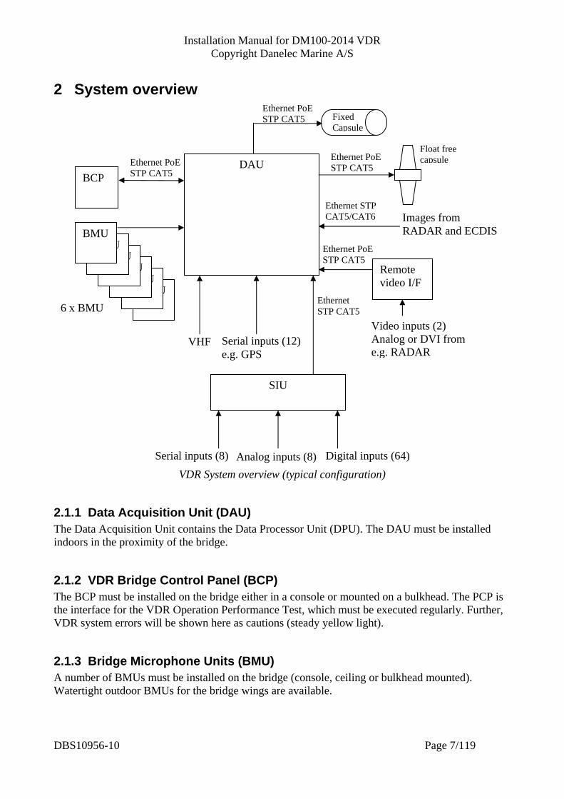
VDR System overview (typical configuration)
2.1.1 Data Acquisition Unit (DAU) The Data Acquisition Unit contains the Data Processor Unit (DPU). The DAU must be installed indoors in the proximity of the bridge.
2.1.2 VDR Bridge Control Panel (BCP) The BCP must be installed on the bridge either in a console or mounted on a bulkhead. The PCP is the interface for the VDR Operation Performance Test, which must be executed regularly. Further, VDR system errors will be shown here as cautions (steady yellow light).
2.1.3 Bridge Microphone Units (BMU) A number of BMUs must be installed on the bridge (console, ceiling or bulkhead mounted). Watertight outdoor BMUs for the bridge wings are available.
BMU BMU
BMU BMU
BMU
DAU
Fixed Capsule
BMU
SIU
Digital inputs (64)
BCP
Ethernet STP CAT5
VHF
6 x BMU
Serial inputs (8)
Video inputs (2) Analog or DVI from e.g. RADAR
Remote video I/F
Ethernet PoESTP CAT5
Serial inputs (12) e.g. GPS
Analog inputs (8)
Ethernet PoE STP CAT5
Ethernet PoESTP CAT5
Ethernet PoESTP CAT5
Ethernet STP CAT5/CAT6 Images from
RADAR and ECDIS
Float free capsule
DBS10956-10 Page 7/119
Installation Manual for DM100-2014 VDR Copyright Danelec Marine A/S
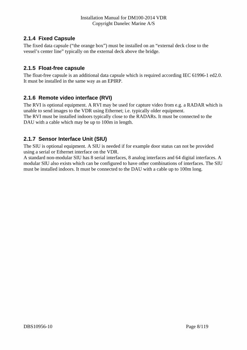
2.1.4 Fixed Capsule The fixed data capsule (“the orange box”) must be installed on an “external deck close to the vessel’s center line” typically on the external deck above the bridge.
2.1.5 Float-free capsule The float-free capsule is an additional data capsule which is required according IEC 61996-1 ed2.0. It must be installed in the same way as an EPIRP.
2.1.6 Remote video interface (RVI) The RVI is optional equipment. A RVI may be used for capture video from e.g. a RADAR which is unable to send images to the VDR using Ethernet; i.e. typically older equipment. The RVI must be installed indoors typically close to the RADARs. It must be connected to the DAU with a cable which may be up to 100m in length.
2.1.7 Sensor Interface Unit (SIU) The SIU is optional equipment. A SIU is needed if for example door status can not be provided using a serial or Ethernet interface on the VDR. A standard non-modular SIU has 8 serial interfaces, 8 analog interfaces and 64 digital interfaces. A modular SIU also exists which can be configured to have other combinations of interfaces. The SIU must be installed indoors. It must be connected to the DAU with a cable up to 100m long.
DBS10956-10 Page 8/119
Installation Manual for DM100-2014 VDR Copyright Danelec Marine A/S
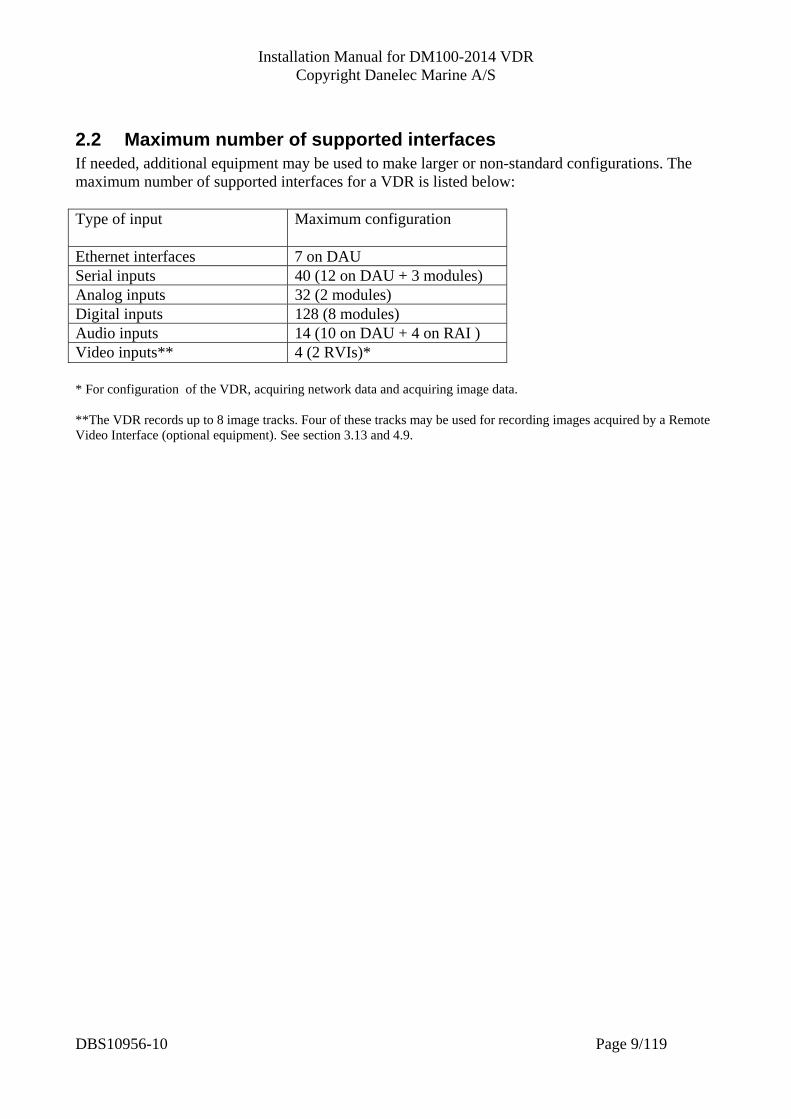
2.2 Maximum number of supported interfaces If needed, additional equipment may be used to make larger or non-standard configurations. The maximum number of supported interfaces for a VDR is listed below: Type of input Maximum configuration
Ethernet interfaces 7 on DAU Serial inputs 40 (12 on DAU + 3 modules) Analog inputs 32 (2 modules) Digital inputs 128 (8 modules) Audio inputs 14 (10 on DAU + 4 on RAI ) Video inputs** 4 (2 RVIs)* * For configuration of the VDR, acquiring network data and acquiring image data. **The VDR records up to 8 image tracks. Four of these tracks may be used for recording images acquired by a Remote Video Interface (optional equipment). See section 3.13 and 4.9.
DBS10956-10 Page 9/119

Installation Manual for DM100-2014 VDR Copyright Danelec Marine A/S
3 Installation The installation must be carefully planned and will depend on the vessel. It is highly recommended that the standard configuration described in section 4.1 and “Appendix A Installation plan for typical VDR configuration” is used as a starting point.
3.1 Installation kit An Installation kit p/n 2302356-10 is supplied with the unit. It contains the following parts: Item Part number Description QTY
Usage
1 3000558-10 Wire holder 9.5x30 18 For holding the cables to the cable support bar
2 4001314-10 M4x16 screw Pan head PZD stainless steel A4
28 For use in conjunction with Item 1
3 4001318-10 M4x30 screw Pan head PZD stainless steel A4
14 For use in conjunction with Item 1
4 4000488-10 Angled IEC power plug 1 For connecting AC power to the power supply in the DAU
5 3300059-12 Holder for IEC plug, 1 Mount this over the IEC power connector for added support.
6 4001294-10 M3x8 screw Pan head PZD stainless steel A4
4 For use in conjunction with item 5 (2 spares are included)
7 4302357-10 Wago 3 way female connector 3.81mm
1 For IAS
8 4302228-10 Wago 4 way female connector 3.81mm
1 For the serial interfaces SI11 and SO11
9 4301060-10 Wago 6 way female connector 3.81mm
6 Capsule, RVI and one spare
10 4301334-10 Wago 8 way female connector 3.81mm
2 Audio 3 and for the cable to the BCP at the BCP
11 4301821-10 Wago 10 way female connector 3.81mm
1 For cable to BCP cable (at the DAU)
12 4301061-10 Wago 12 way female connector 3.81mm
1 Serial interfaces SI01-SI03 (IEC 61162-2)
13 4301062-10 Wago 16 way female connector 3.81mm
1 Audio 1
14 4301821-10 Wago 10 way female connector 3.81mm 734-210 cage clamp
1 For the BCP cable at the DAU
15 4302128-10 Wago 14 way female connector 3.81mm
2 Audio 2 and Serial interfaces SI04-SI10 (IEC 61162-1)
16 4300986-10 Push button for 3.5mm and 3.81mm Wago connectors
2 Tool for opening the wire clamps inside the Wago connectors
17 4302619-10 Wago key tool 236-332 (for 236-404 )
2 Tool for opening the wire clamps on the terminal block on the microphones
18 Key for the DAU 1 For locking the DAU
DBS10956-10 Page 10/119

Installation Manual for DM100-2014 VDR Copyright Danelec Marine A/S
3.2 DAU The DAU must be installed on a bulkhead, which can easily carry the weight of the DAU. The DAU must be protected from rain, seawater and direct sunlight. Consult Appendix C Installation of DAU The weight of the DM100 DAU is 11Kg / 25lbs
3.3 Earth stud The earth stud located inside the DAU (right front corner) must be connected to ship’s earth. The diameter of the earth stud is 6mm. The earth strap must be fitted with an M6 ring crimp terminal.
3.4 Power requirements The power supply must be connected the ship’s main power source (110-230AC). The AC power must be backed up by the vessels emergency power (automatically switch over). The cables must be as short as possible and have a conductor area of 0,75mm2 minimum for the AC input. The angled IEC mains connector supplied with the DAU must be used for the AC input. The power consumption for the DAU is 75W.
3.5 Grounding of data cables All data cables must be shielded with a braid screen.
Grounding of data cables The braid screen, for cables terminated with a Wago terminal block, must be connected to the cable support beam as shown above. This includes cables to the audio module, serial module, BCP and IAS.
DBS10956-10 Page 11/119
Installation Manual for DM100-2014 VDR Copyright Danelec Marine A/S
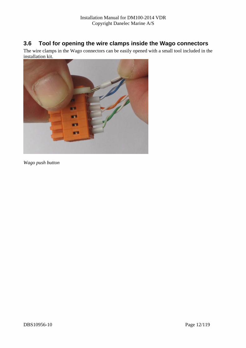
3.6 Tool for opening the wire clamps inside the Wago connectors The wire clamps in the Wago connectors can be easily opened with a small tool included in the installation kit.
Wago push button
DBS10956-10 Page 12/119
Installation Manual for DM100-2014 VDR Copyright Danelec Marine A/S
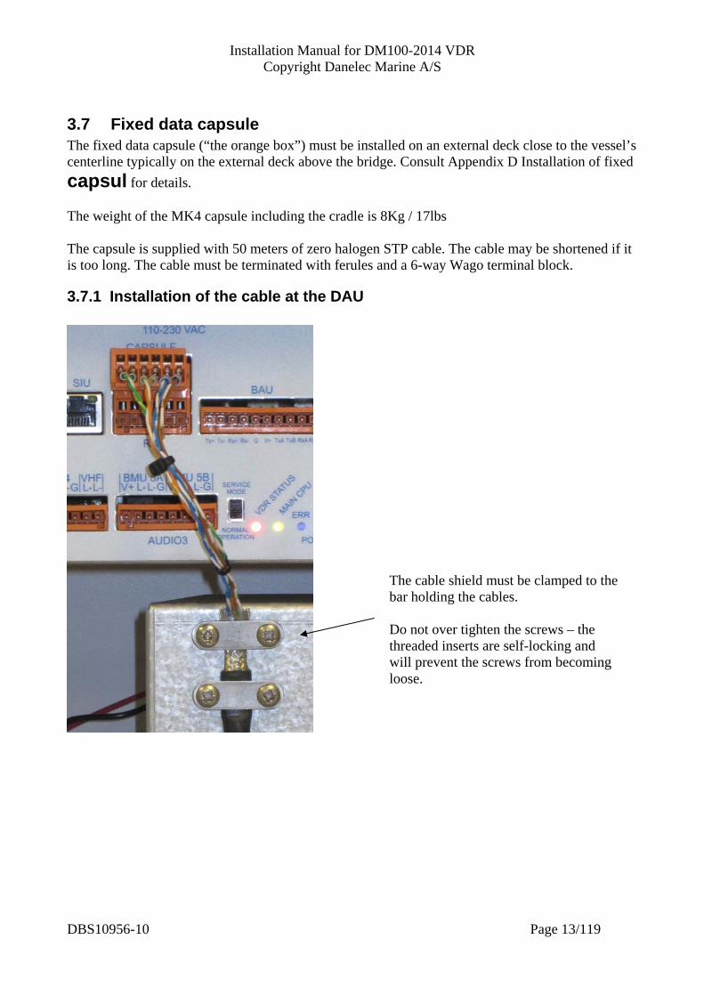
3.7 Fixed data capsule The fixed data capsule (“the orange box”) must be installed on an external deck close to the vessel’s centerline typically on the external deck above the bridge. Consult Appendix D Installation of fixed capsul for details. The weight of the MK4 capsule including the cradle is 8Kg / 17lbs The capsule is supplied with 50 meters of zero halogen STP cable. The cable may be shortened if it is too long. The cable must be terminated with ferules and a 6-way Wago terminal block.
3.7.1 Installation of the cable at the DAU
The cable shield must be clamped to the bar holding the cables. Do not over tighten the screws – the threaded inserts are self-locking and will prevent the screws from becoming loose.
DBS10956-10 Page 13/119

Installation Manual for DM100-2014 VDR Copyright Danelec Marine A/S
3.7.2 Description of Cable from DPU to MK4 capsule
Picture showing the factory supplied cable If the cable is shortened, pull the cable shield and drain wire back over the jacket and fix it with tape.
Picture showing how to make the cable on board if shortened
Pin 1 Green/white Pin 2 Green Pin 3 Orange/white Pin 4 Orange Pin 5 Blue and blue/white Pin 6 Brown and brown/white
Cable termination at the DAU
DBS10956-10 Page 14/119
Installation Manual for DM100-2014 VDR Copyright Danelec Marine A/S
3.8 Float-free data capsule The float-free data capsule must be installed on a bulkhead outside where obstacles will not prevent the capsule floating away from the vessel. The float-free capsule should be installed in a location guided by COMSAR.Circ 32 (Chap 4.10) http://www.imo.org/blast/blastDataHelper.asp?data_id=10750&filename=32.pdf The cable used from the DPU to junction box for the float-free is identical to the cable used for the fixed capsule see section 3.7.1 and 3.7.2. The Wago 6-way must be connected to the “FLOAT FREE” receptor on the DPU. Consult Appendix E Installation of float free capsule for more details.
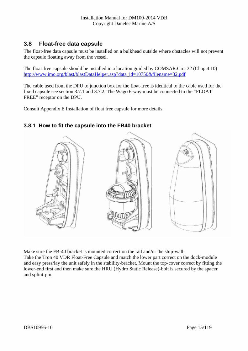
3.8.1 How to fit the capsule into the FB40 bracket
Make sure the FB-40 bracket is mounted correct on the rail and/or the ship-wall. Take the Tron 40 VDR Float-Free Capsule and match the lower part correct on the dock-module and easy press/lay the unit safely in the stability-bracket. Mount the top-cover correct by fitting the lower-end first and then make sure the HRU (Hydro Static Release)-bolt is secured by the spacer and splint-pin.
DBS10956-10 Page 15/119
Installation Manual for DM100-2014 VDR Copyright Danelec Marine A/S
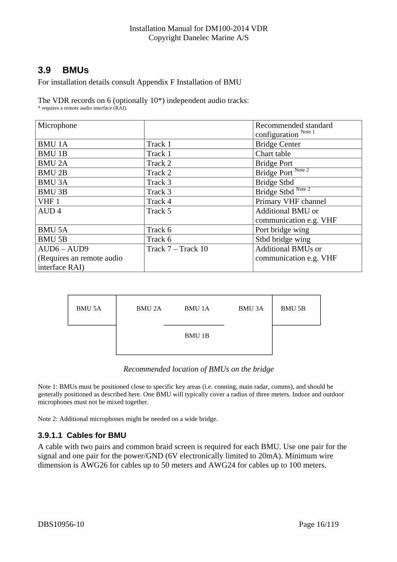
3.9 BMUs For installation details consult Appendix F Installation of BMU The VDR records on 6 (optionally 10*) independent audio tracks: * requires a remote audio interface (RAI). Microphone Recommended standard
configuration Note 1
BMU 1A Track 1 Bridge Center BMU 1B Track 1 Chart table BMU 2A Track 2 Bridge Port BMU 2B Track 2 Bridge Port Note 2 BMU 3A Track 3 Bridge Stbd BMU 3B Track 3 Bridge Stbd Note 2
VHF 1 Track 4 Primary VHF channel AUD 4 Track 5 Additional BMU or
communication e.g. VHF BMU 5A Track 6 Port bridge wing BMU 5B Track 6 Stbd bridge wing AUD6 – AUD9 (Requires an remote audio interface RAI)
Track 7 – Track 10 Additional BMUs or communication e.g. VHF
BMU 1B
BMU 3ABMU 2A BMU 5B BMU 1ABMU 5A
Recommended location of BMUs on the bridge Note 1: BMUs must be positioned close to specific key areas (i.e. conning, main radar, comms), and should be generally positioned as described here. One BMU will typically cover a radius of three meters. Indoor and outdoor microphones must not be mixed together. Note 2: Additional microphones might be needed on a wide bridge.
3.9.1.1 Cables for BMU A cable with two pairs and common braid screen is required for each BMU. Use one pair for the signal and one pair for the power/GND (6V electronically limited to 20mA). Minimum wire dimension is AWG26 for cables up to 50 meters and AWG24 for cables up to 100 meters.
DBS10956-10 Page 16/119

Installation Manual for DM100-2014 VDR Copyright Danelec Marine A/S
3.9.2 VHF1 The sensitivity for the VHF1 input is 0.775V RMS. The primary VHF radio must be connected to this input. A cable with only one pair and common braid screen is needed. Minimum wire dimension is AWG26 for cables up to 50 meters and AWG24 for cables up to100 meters.
3.9.3 AUD4 An additional microphone may be connected to this input. This channel may also be used for recording other relevant optional communication. The primary VHF radio must not be connected to AUD4. The sensitivity of AUD4 is 0,775V RMS. V+ and G shall only be used when a BMU is connected to AUD4. Minimum wire dimension is AWG26 for cables up to 50 meters and AWG24 for cables up to 100 meters.
3.9.3.1 Filter characteristic for AUD4 The “BMU 4 active” parameter (see section 4.7) determines the filter characteristic. It also whether determines whether AUD4 is applicable for a BMU or a VHF set. Frequency response Use input for Parameter “BMU 4 Active” checked 150-6000Hz BMU Parameter “BMU 4 Active” unchecked 150-3500Hz VHF or other communication
equipment
3.9.4 AUD6 – AUD9 An additional remote audio interface maybe connected to the DPU. This will add four more audio inputs to the system. The properties for these inputs are identical to the properties for AUD4 described in section 3.9.3.
3.10 BCP The VDR Bridge Control Panel must be connected to the VDR using a screened cable with 4 pairs. A standard STP CAT5 cable (with 4 pairs) is suitable. Minimum wire dimension is AWG26 for cables up to 25 meters and AWG24 for cables up to 50 meters. The BCP requires a 121x121mm panel cutout. The size is 144x144mm and requires 100mm behind the panel. See also Appendix G Installation of B
DBS10956-10 Page 17/119

Installation Manual for DM100-2014 VDR Copyright Danelec Marine A/S
3.11 Serial data It is highly recommended that the following guidelines are followed where possible. Serial interfaces on the DAU I/F type (note 1) Recommended use (fits standard configuration) SI00 IEC 61162-2 AIS SI01 IEC 61162-2 Auto Pilot SI02 IEC 61162-2 Engine management system SI03 IEC 61162-2 Spare SI04 IEC 61162-1 GPS SI05 IEC 61162-1 Speed log SI06 IEC 61162-1 Gyro SI07 IEC 61162-1 Anemometer SI08 IEC 61162-1 Echo sounder SI09 IEC 61162-1 BNWAS SI10 IEC 61162-1 Inclinometer SI11 IEC 61162-1 (RX) Bridge Alarm Management SO11 IEC 61162-1 (TX) Bridge Alarm Management Note 1: Max baud rate for the IEC 61162-1 interfaces is 9600 and max baud rate for the IEC 61162-2 interfaces is 38400. When planning the allocation of the serial channels the following rules must be observed: Date and time Must be recorded Ship position Must be recorded Speed Must be recorded Heading Must be recorded Bridge audio Must be recorded Communication audio Must be recorded Radar images Must be recorded ECDIS Must be recorded Echo sounder Must be recorded Main alarms Must be recorded BNWAS 1st stage alarm (main alarm) Must be recorded Engine order and response Must be recorded Rudder order and response Must be recorded Hull openings status Must be recorded Watertight and fire doors Must be recorded Acceleration and hull stresses Must be recorded if equipment is installed Wind speed and direction Must be recorded if equipment is installed Inclinometer Must be recorded if equipment is installed Bridge alarm system Must be interfaced to if
DBS10956-10 Page 18/119
Installation Manual for DM100-2014 VDR Copyright Danelec Marine A/S
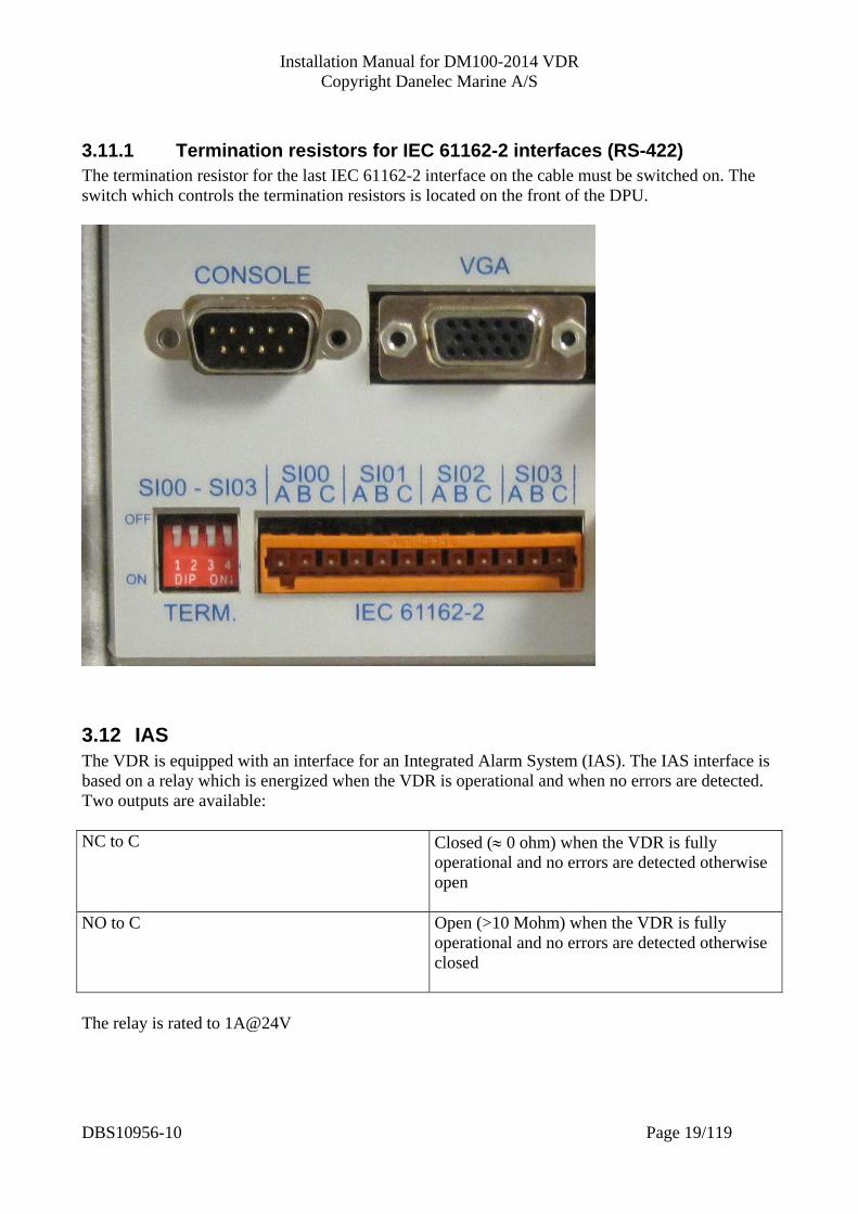
3.11.1 Termination resistors for IEC 61162-2 interfaces (RS-422) The termination resistor for the last IEC 61162-2 interface on the cable must be switched on. The switch which controls the termination resistors is located on the front of the DPU.
3.12 IAS The VDR is equipped with an interface for an Integrated Alarm System (IAS). The IAS interface is based on a relay which is energized when the VDR is operational and when no errors are detected. Two outputs are available: NC to C Closed (≈ 0 ohm) when the VDR is fully
operational and no errors are detected otherwise open
NO to C Open (>10 Mohm) when the VDR is fully operational and no errors are detected otherwise closed
The relay is rated to 1A@24V
DBS10956-10 Page 19/119
Installation Manual for DM100-2014 VDR Copyright Danelec Marine A/S
3.13 Image capture interface Image capture is done using the LAN port on the DPU (Ethernet/IEC 61162-450) or by using external remote video interfaces.
3.13.1 Recommended standard configuration for image capture Image source Image channel in
the VDR Ethernet interface on VDR Note 1
Interface on Remote video interface Note 2
S-band RADAR VD 1 LAN 2 VD1 on RVI connected to the RVI port on the DPU
X-band RADAR VD 2 LAN 3 VD2 on RVI connected to the RVI port on the DPU
ECDIS 1 VD 3 LAN 4 ECDIS 2 VD 4 LAN 5 Note 1: If the source is connected directly to the VDR (using an Ethernet cable). Note 2: If the source is unable to send its images using Ethernet (i.e. older equipment where the images must be captured locally using a remote video interface).
3.13.2 Description of remote video interfaces Two remote video interfaces may be connected to the DPU, each having interfaces for two video sources. RVI 02-004 P/N 1302358: Remote video interface with two 5xBNC analog video interfaces. RVI 02-004D P/N 1302365: Remote video interface with two DVI-I interfaces. A DVI-I interface may be used as a single link DVI interface or as an analog interface with the same properties as the interfaces on RVI 02-004. If the video signal is transmitted from the source using 5 coaxial cables, then utilize the RVI 02-004 (rather than the RVI 02-004D) with an adaptor cable in order to avoid unnecessary problems. It is recommended that the first remote video interface is connected to the “RVI” port on the DPU. A second remote video interface may be connected to the “RDI” port on the DPU. If the “RDI” port is occupied, a remote video interface with built-in power supply may be used. This type of video interface can be connected to one of the LAN ports on the DPU. P/N 1000723 Remote Video Interface RVI inclusive analog video module (AC power) P/N 1302152 Remote Video Interface inclusive digital video module (AC power)
DBS10956-10 Page 20/119
Installation Manual for DM100-2014 VDR Copyright Danelec Marine A/S
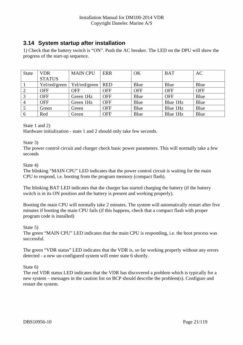
3.14 System startup after installation 1) Check that the battery switch is “ON”. Push the AC breaker. The LED on the DPU will show the progress of the start-up sequence. State VDR
STATUS MAIN CPU ERR OK BAT AC
1 Yel/red/green Yel/red/green RED Blue Blue Blue 2 OFF OFF OFF OFF OFF OFF 3 OFF Green 1Hz OFF Blue OFF Blue 4 OFF Green 1Hz OFF Blue Blue 1Hz Blue 5 Green Green OFF Blue Blue 1Hz Blue 6 Red Green OFF Blue Blue 1Hz Blue State 1 and 2) Hardware initialization - state 1 and 2 should only take few seconds. State 3) The power control circuit and charger check basic power parameters. This will normally take a few seconds State 4) The blinking “MAIN CPU” LED indicates that the power control circuit is waiting for the main CPU to respond, i.e. booting from the program memory (compact flash). The blinking BAT LED indicates that the charger has started charging the battery (if the battery switch is in its ON position and the battery is present and working properly). Booting the main CPU will normally take 2 minutes. The system will automatically restart after five minutes if booting the main CPU fails (if this happens, check that a compact flash with proper program code is installed) State 5) The green “MAIN CPU” LED indicates that the main CPU is responding, i.e. the boot process was successful. The green “VDR status” LED indicates that the VDR is, so far working properly without any errors detected - a new un-configured system will enter state 6 shortly. State 6) The red VDR status LED indicates that the VDR has discovered a problem which is typically for a new system – messages in the caution list on BCP should describe the problem(s). Configure and restart the system.
DBS10956-10 Page 21/119

Installation Manual for DM100-2014 VDR Copyright Danelec Marine A/S
4 Configuration The system is configured as described below: Setup of configurator PC 4.2 System login 4.3 Configuration of vessel ID 4.4 Configuration of UTC and position source 4.5 Configuration of serial interfaces 4.6 Configuration of position source and GPS antenna position 4.6.1 Configuration of network interface 4.7 Configuration of audio interfaces 4.8 Configuration of RADAR and ECDIS interface 4.9 Backup of configuration file 4.10 Configuration of SIU (VDR only) See the installation manual for SIU Backup of configuration file 4.10
4.1 Default configuration for the VDR The Boot Flash contains a default configuration, which corresponds to the installation guidelines. I/F I/F type Channel ID text Comm. setup Timeout Active NMEA Formatters SI00 IEC 61162-2 AIS 38400,8,N,1 Enabled Yes VDM,VDO SI01 IEC 61162-2 Autopilot 4800,8,N,1 Disabled Yes RSA, HTD SI02 IEC 61162-2 Engine control 4800,8,N,1 Disabled Yes XDR SI03 IEC 61162-2 Spare 4800,8,N,1 Disabled Yes SI04 IEC 61162-1 GPS 4800,8,N,1 Enabled Yes ZDA,DTM,GLL,VTG SI05 IEC 61162-1 Speed log 4800,8,N,1 Enabled Yes VHW SI06 IEC 61162-1 Gyro 4800,8,N,1 Enabled Yes ROT,HDT SI07 IEC 61162-1 Anemometer 4800,8,N,1 Disabled Yes MWV SI08 IEC 61162-1 Echo sounder 4800,8,N,1 Enabled Yes DPT SI09 IEC 61162-1 BNWAS 4800,8,N,1 Enabled Yes ALR SI10 IEC 61162-1 Inclinometer 4800,8,N,1 Disabled Yes SI11 IEC 61162-1 BAM 4800,8,N,1 Disabled Yes ALR Microphone Channel ID text Active BMU (power)
active Source type
BMU 1A Bridge Center Yes Yes BMU 003 BMU 1B Chart table Yes Yes BMU 003 BMU 2A Bridge port Yes Yes BMU 003 BMU 2B Bridge port No Yes BMU 003 BMU 3A Bridge stbd Yes Yes BMU 003 BMU 3B Bridge stbd No Yes BMU 003 BMU 5A Port bridge wing Yes Yes BMU 004 BMU 5B Stbd bridge wing Yes Yes BMU 004 VHF 1 Primary VHF channel Yes No AUD 4 Yes No AUD 6 - 9 No No
DBS10956-10 Page 22/119
Installation Manual for DM100-2014 VDR Copyright Danelec Marine A/S
Image channel Resolution* Active Image input type Source type 1 1600x1200 Yes Ethernet S-band RADAR 2 1600x1200 Yes Ethernet X-band RADAR 3 1600x1200 Yes Ethernet ECDIS 1 4 1600x1200 Yes Ethernet ECDIS 2 * Not relevant for images received over Ethernet.
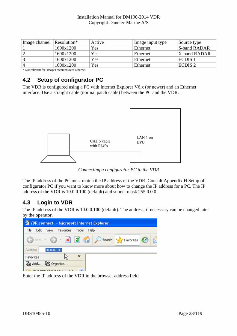
4.2 Setup of configurator PC The VDR is configured using a PC with Internet Explorer V6.x (or newer) and an Ethernet interface. Use a straight cable (normal patch cable) between the PC and the VDR.
CAT 5 cable with RJ45s
LAN 1 on DPU
Connecting a configurator PC to the VDR The IP address of the PC must match the IP address of the VDR. Consult Appendix H Setup of configurator PC if you want to know more about how to change the IP address for a PC. The IP address of the VDR is 10.0.0.100 (default) and subnet mask 255.0.0.0.
4.3 Login to VDR The IP address of the VDR is 10.0.0.100 (default). The address, if necessary can be changed later by the operator. Enter the IP address of the VDR in the browser address field
DBS10956-10 Page 23/119
Installation Manual for DM100-2014 VDR Copyright Danelec Marine A/S
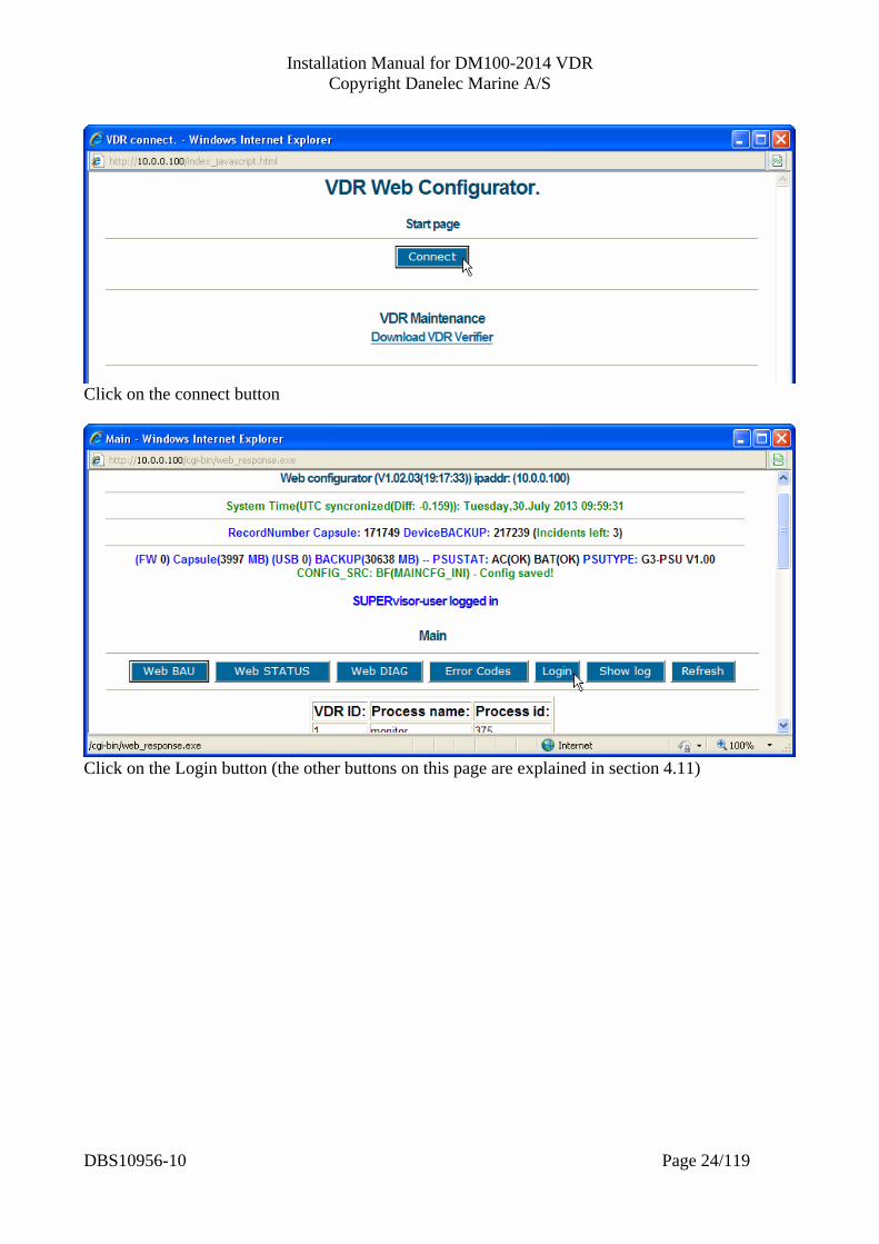
Click on the connect button
Click on the Login button (the other buttons on this page are explained in section 4.11)
DBS10956-10 Page 24/119

Installation Manual for DM100-2014 VDR Copyright Danelec Marine A/S
Enter User (ID) and password and click on Submit The default user is “svdrsuper” The default password is “danelec..”
DBS10956-10 Page 25/119
Installation Manual for DM100-2014 VDR Copyright Danelec Marine A/S
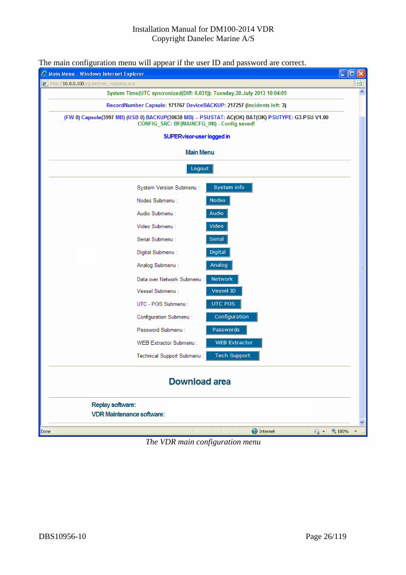
The main configuration menu will appear if the user ID and password are correct.
The VDR main configuration menu
DBS10956-10 Page 26/119
Installation Manual for DM100-2014 VDR Copyright Danelec Marine A/S
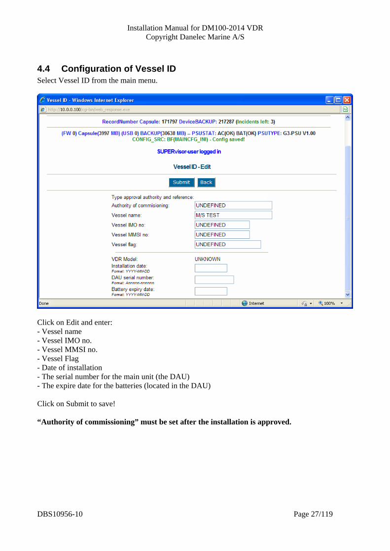
4.4 Configuration of Vessel ID Select Vessel ID from the main menu.
Click on Edit and enter: - Vessel name - Vessel IMO no. - Vessel MMSI no. - Vessel Flag - Date of installation - The serial number for the main unit (the DAU) - The expire date for the batteries (located in the DAU) Click on Submit to save! “Authority of commissioning” must be set after the installation is approved.
DBS10956-10 Page 27/119
Installation Manual for DM100-2014 VDR Copyright Danelec Marine A/S
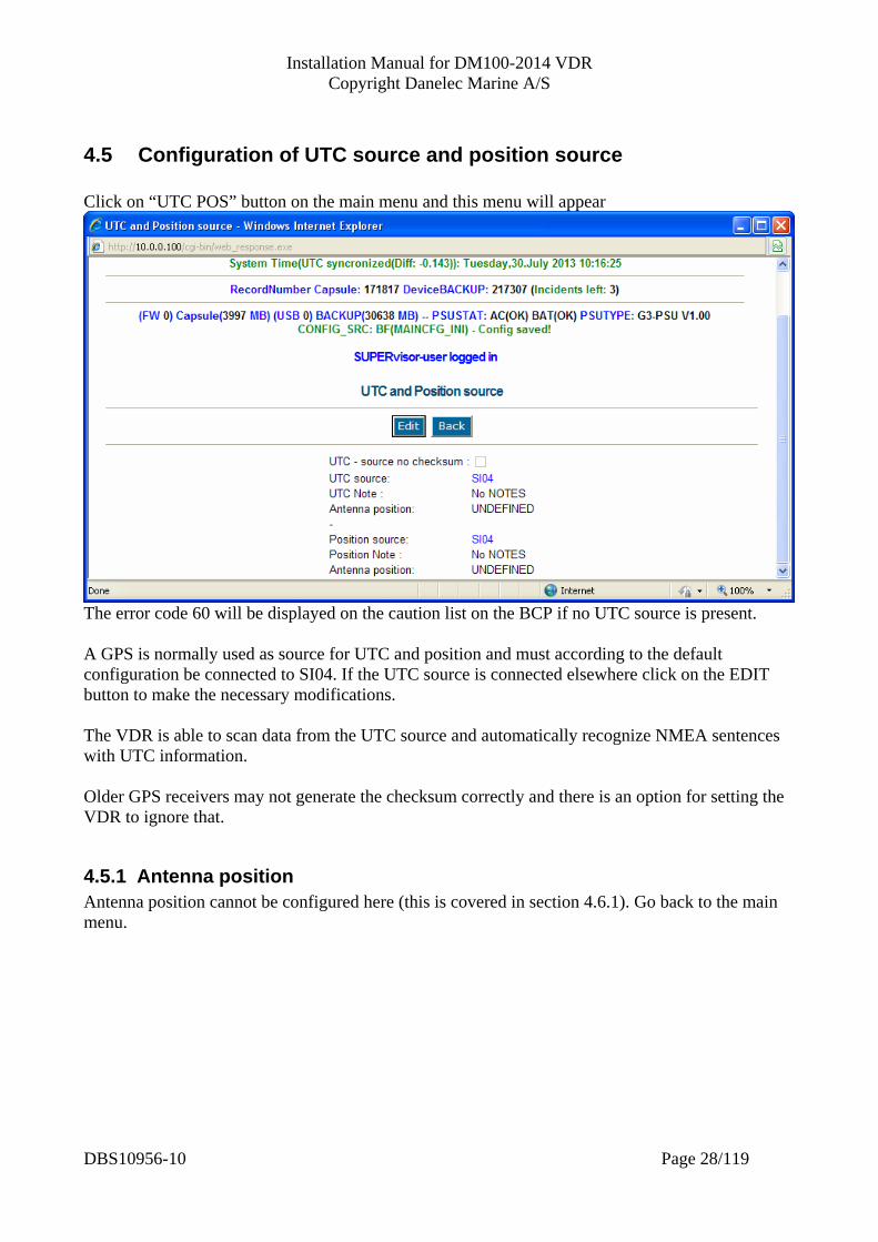
4.5 Configuration of UTC source and position source Click on “UTC POS” button on the main menu and this menu will appear
The error code 60 will be displayed on the caution list on the BCP if no UTC source is present. A GPS is normally used as source for UTC and position and must according to the default configuration be connected to SI04. If the UTC source is connected elsewhere click on the EDIT button to make the necessary modifications. The VDR is able to scan data from the UTC source and automatically recognize NMEA sentences with UTC information. Older GPS receivers may not generate the checksum correctly and there is an option for setting the VDR to ignore that.
4.5.1 Antenna position Antenna position cannot be configured here (this is covered in section 4.6.1). Go back to the main menu.
DBS10956-10 Page 28/119

Installation Manual for DM100-2014 VDR Copyright Danelec Marine A/S
4.6 Configuration of serial channels Select the serial submenu (click on Serial) from the main menu.
Serial sub menu
Slot Position of serial module #1. Informational only, the position of serial module #1 is fixed. Please notice that serial module #1 is embedded on the SAP board in the DM100 DPU. Active Informational only, serial module #1 cannot be disabled Name Type name for the serial module (do not change) Node id Reserved for future use, do not change. Number of channels Informational only
DBS10956-10 Page 29/119

Installation Manual for DM100-2014 VDR Copyright Danelec Marine A/S
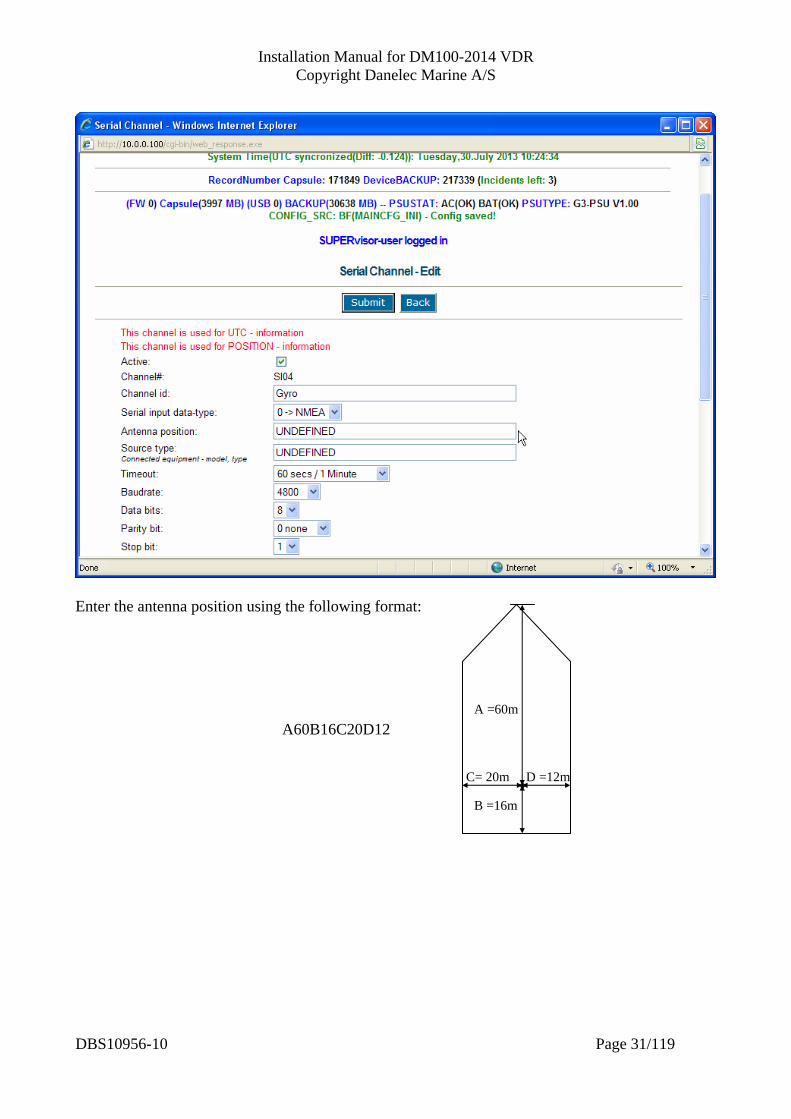
4.6.1 Setup of antenna position for UTC and position source Click on the “Channels” button on the “Serial” submenu and this menu will appear.
Select the serial input channel to where the UTC source is connected (this is normally SI04, i.e. click on “next” four times) and then “Edit”.
DBS10956-10 Page 30/119
Installation Manual for DM100-2014 VDR Copyright Danelec Marine A/S
Enter the antenna position using the following format:
A =60m A60B16C20D12
C= 20m D =12m
B =16m
DBS10956-10 Page 31/119

Installation Manual for DM100-2014 VDR Copyright Danelec Marine A/S
4.6.2 Other parameters for a serial channel Active Is used to enable/disable the channel. Channel ID There are several descriptive fields related to the configuration for a serial channel. The text entered in this field will be used in conjunction with the replay software. The typical use of this field is to store the generic term for the connected equipment e.g. GPS. Serial input data type This parameter will not affect whether data is recorded or not, but may affect how data is displayed in the debugging and monitoring tools for the VDR. Antenna position/source Descriptive field used for indicating the antenna position for the UTC and position source. This field is named “source info” for all other channels and may be used for optional information. Source type Descriptive field - must be used for unambiguously describing the equipment connected to this interface i.e. type, model. Timeout The maximum allowed pause on the serial line before an alarm is generated. Timeout cannot be disabled for UTC and position source. Baud rate, data bits, parity bits and stop bits The communication parameters for the serial line. Select NMEA version/IEC 61162 Informative only. Does not affect the operation of the VDR or replay software. Note Optional informational text. List of NMEA formatters The list must contain the NMEA formatter for the sentences to be received on this serial channel. This is a required by the VDR standard. The VDR will not generate and alarm if a sentence is missing. However, the VDR verification tool (the VDR Verifier) will check this. Proprietary NMEA format description The VDR standard requires that information about the format for proprietary NMEA sentences is included in the VDR configuration. The information must be sufficient for the authorities to decode the information. Please notice that it is unacceptable only to specify an URL (Internet link) to the relevant information. Maximum size is 2000 characters.
DBS10956-10 Page 32/119
Installation Manual for DM100-2014 VDR Copyright Danelec Marine A/S
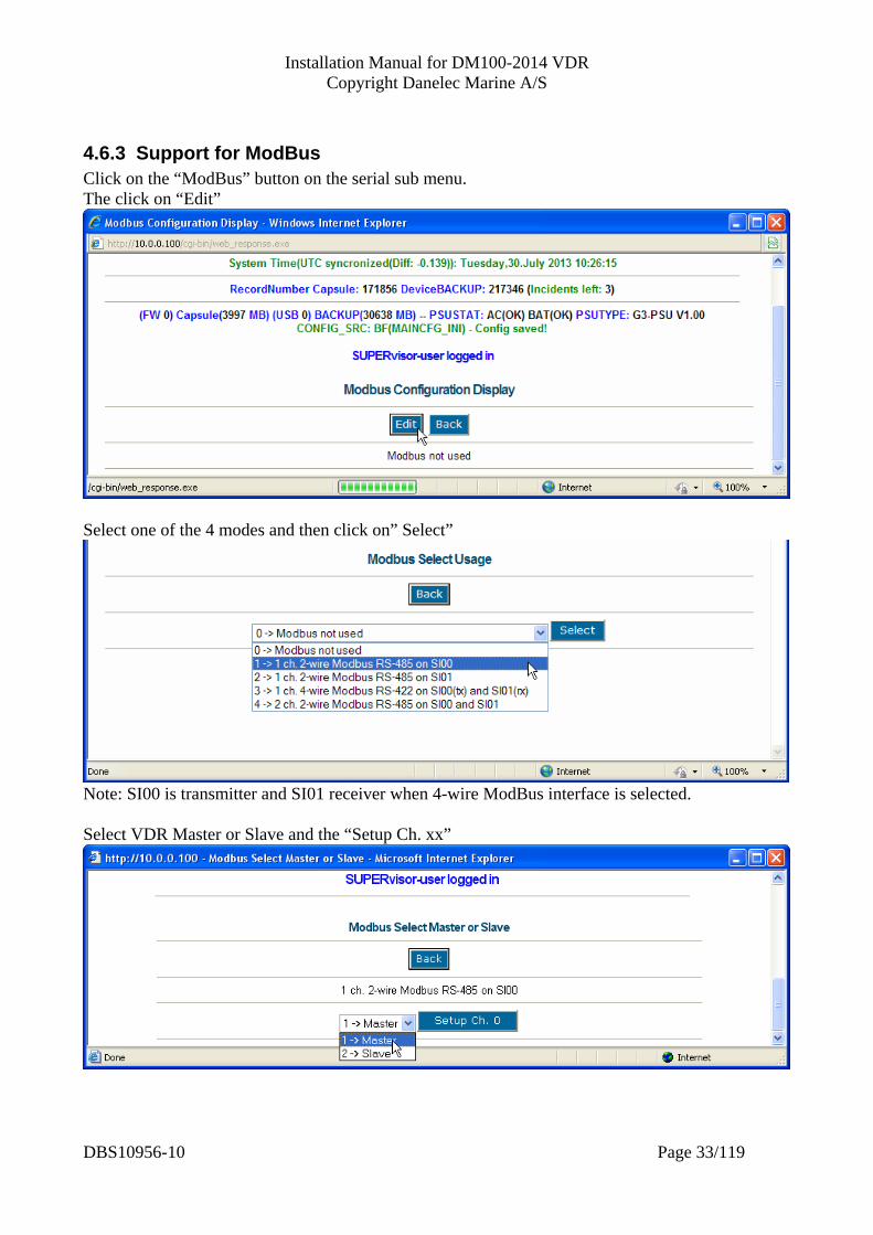
4.6.3 Support for ModBus Click on the “ModBus” button on the serial sub menu. The click on “Edit”
Select one of the 4 modes and then click on” Select”
Note: SI00 is transmitter and SI01 receiver when 4-wire ModBus interface is selected. Select VDR Master or Slave and the “Setup Ch. xx”
DBS10956-10 Page 33/119
Installation Manual for DM100-2014 VDR Copyright Danelec Marine A/S
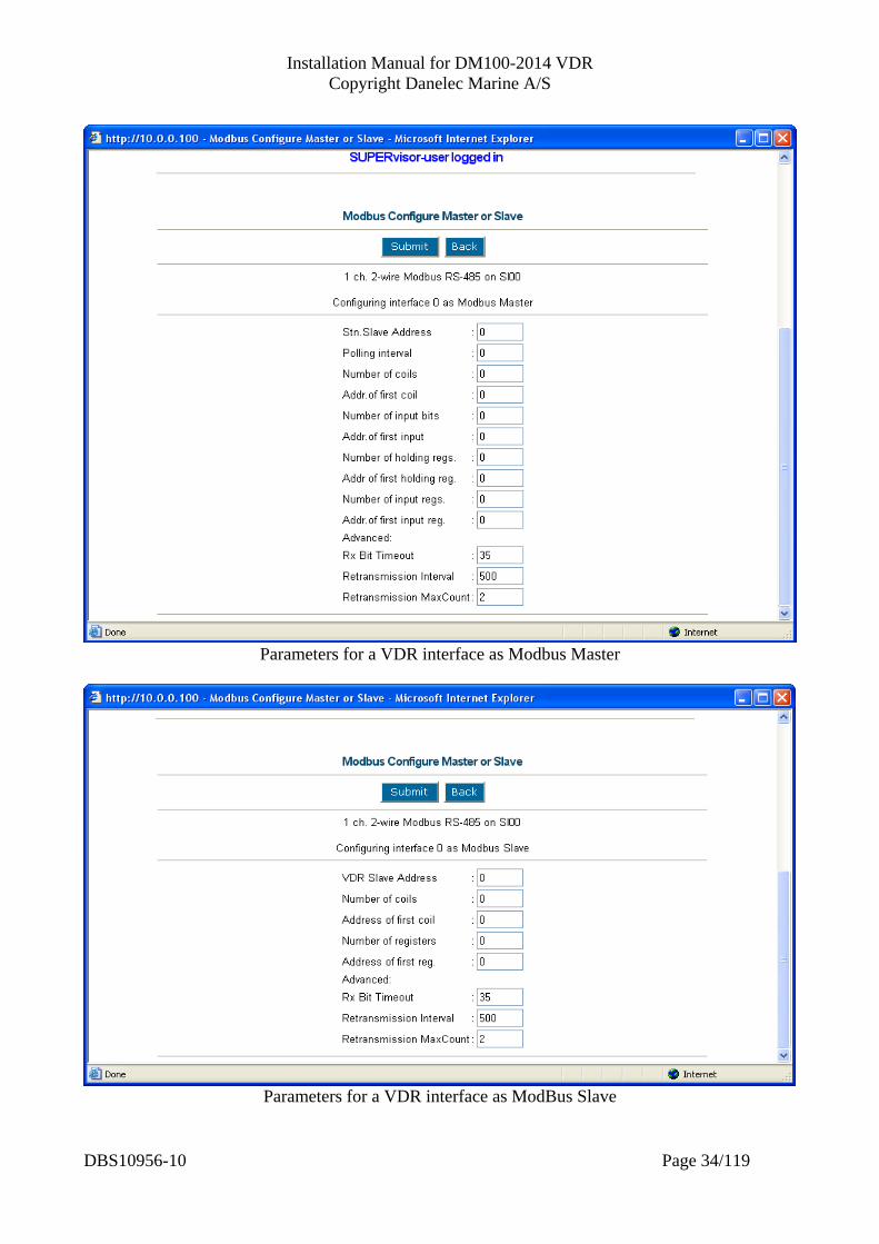
Parameters for a VDR interface as Modbus Master
Parameters for a VDR interface as ModBus Slave
DBS10956-10 Page 34/119

Installation Manual for DM100-2014 VDR Copyright Danelec Marine A/S
4.7 Configuration of data capture via network Select the network submenu from the main menu (click on Network).
4.7.1 Configuration of “Data over Network” channels Click on the “Channels” button and this configuration page will be displayed.
DBS10956-10 Page 35/119
Installation Manual for DM100-2014 VDR Copyright Danelec Marine A/S
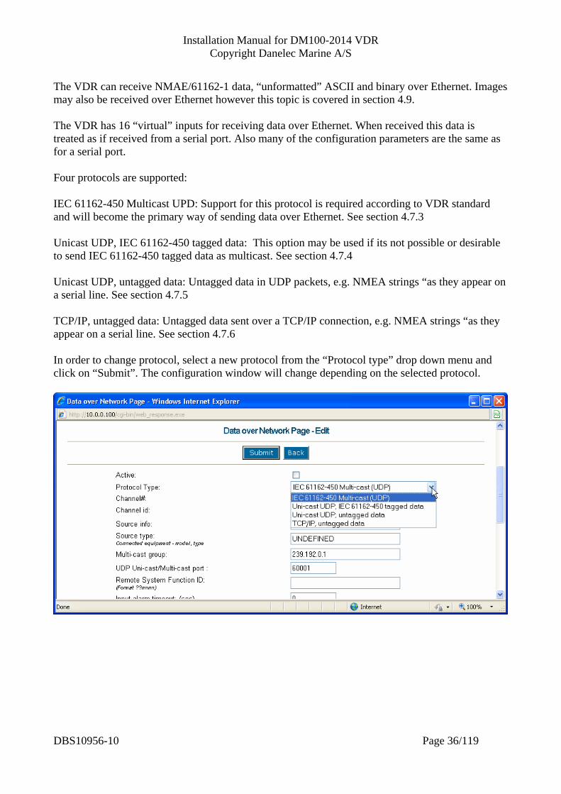
The VDR can receive NMAE/61162-1 data, “unformatted” ASCII and binary over Ethernet. Images may also be received over Ethernet however this topic is covered in section 4.9. The VDR has 16 “virtual” inputs for receiving data over Ethernet. When received this data is treated as if received from a serial port. Also many of the configuration parameters are the same as for a serial port. Four protocols are supported: IEC 61162-450 Multicast UPD: Support for this protocol is required according to VDR standard and will become the primary way of sending data over Ethernet. See section 4.7.3 Unicast UDP, IEC 61162-450 tagged data: This option may be used if its not possible or desirable to send IEC 61162-450 tagged data as multicast. See section 4.7.4 Unicast UDP, untagged data: Untagged data in UDP packets, e.g. NMEA strings “as they appear on a serial line. See section 4.7.5 TCP/IP, untagged data: Untagged data sent over a TCP/IP connection, e.g. NMEA strings “as they appear on a serial line. See section 4.7.6 In order to change protocol, select a new protocol from the “Protocol type” drop down menu and click on “Submit”. The configuration window will change depending on the selected protocol.
DBS10956-10 Page 36/119

Installation Manual for DM100-2014 VDR Copyright Danelec Marine A/S
4.7.2 Configuration of network channel in general (common parameters)
Active Is used to enable/disable the virtual channel Protocol type The VDR supports four communication protocols, see section 4.7 Channel# The system ID for this virtual channel (can not be changed). Channel ID There are several descriptive fields related to the configuration for a serial channel. The text entered in this field will be used in conjunction with the replay software. The typical use of this field is to store the generic term for the connected equipment e.g. GPS. Source info Additional optional information about the source, e.g. its location. Source type Mandatory descriptive field - must be used for unambiguously describing the equipment connected to this interface; i.e. type, model.
DBS10956-10 Page 37/119
Installation Manual for DM100-2014 VDR Copyright Danelec Marine A/S
Input alarm timeout The maximum allowed pause between receipt of data before an alarm is generated. NMEA version Informative only. Does not affect the operation of the VDR or replay software. Note Optional informative text. List of NMEA formatters The list must contain the NMEA formatter for the sentences to be received on this serial channel. This is a requirement of the VDR standard. The VDR will not generate an alarm if a sentence is missing. However, the VDR verification tool (the VDR Verifier) will check this. Proprietary NMEA format description The VDR standard requires that information about the format for proprietary NMEA sentences is included in the VDR configuration. The information must be sufficient for the authorities to decode the information. Please notice that it is unacceptable only to specify an URL (Internet link) to the relevant information. Maximum size is 2000 characters.
DBS10956-10 Page 38/119
Installation Manual for DM100-2014 VDR Copyright Danelec Marine A/S
4.7.3 Configuration of IEC 61162-450 Multicast UPD
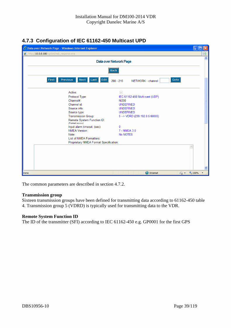
The common parameters are described in section 4.7.2.
ransmission group roups have been defined for transmitting data according to 61162-450 table
emote System Function ID according to IEC 61162-450 e.g. GP0001 for the first GPS
TSixteen transmission g4. Transmission group 5 (VDRD) is typically used for transmitting data to the VDR. RThe ID of the transmitter (SFI)
DBS10956-10 Page 39/119
Installation Manual for DM100-2014 VDR Copyright Danelec Marine A/S
4.7.4 Configuration of Unicast UDP, IEC 61162-450 tagged data
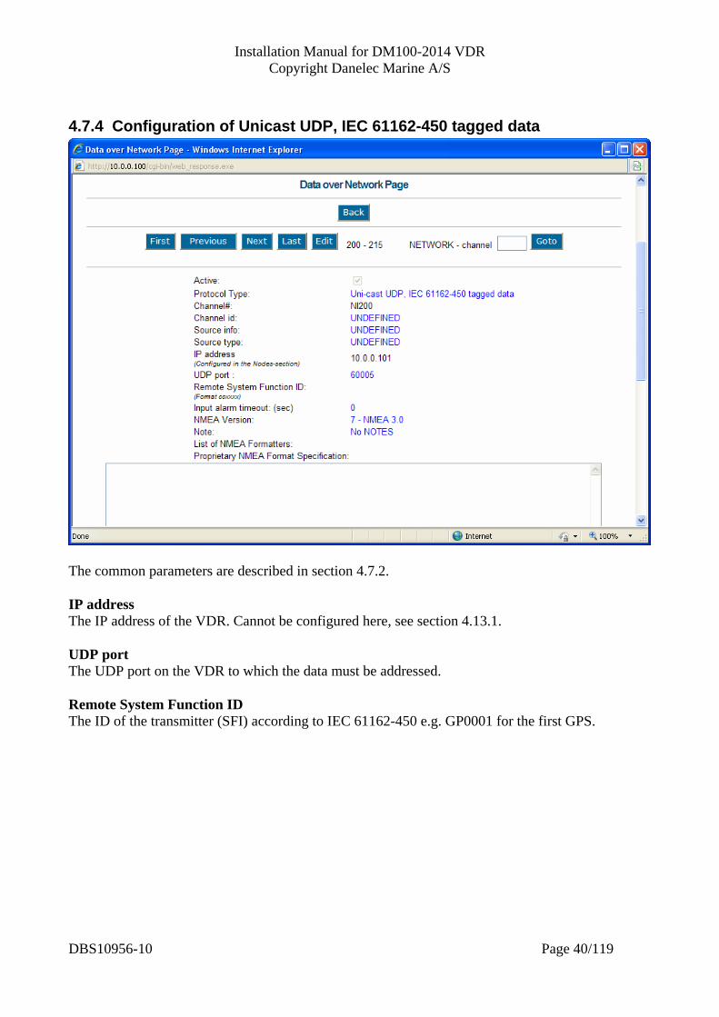
The common parameters are described in section 4.7.2. IP address The IP address of the VDR. Cannot be configured here, see section 4.13.1. UDP port The UDP port on the VDR to which the data must be addressed. Remote System Function ID The ID of the transmitter (SFI) according to IEC 61162-450 e.g. GP0001 for the first GPS.
DBS10956-10 Page 40/119
Installation Manual for DM100-2014 VDR Copyright Danelec Marine A/S
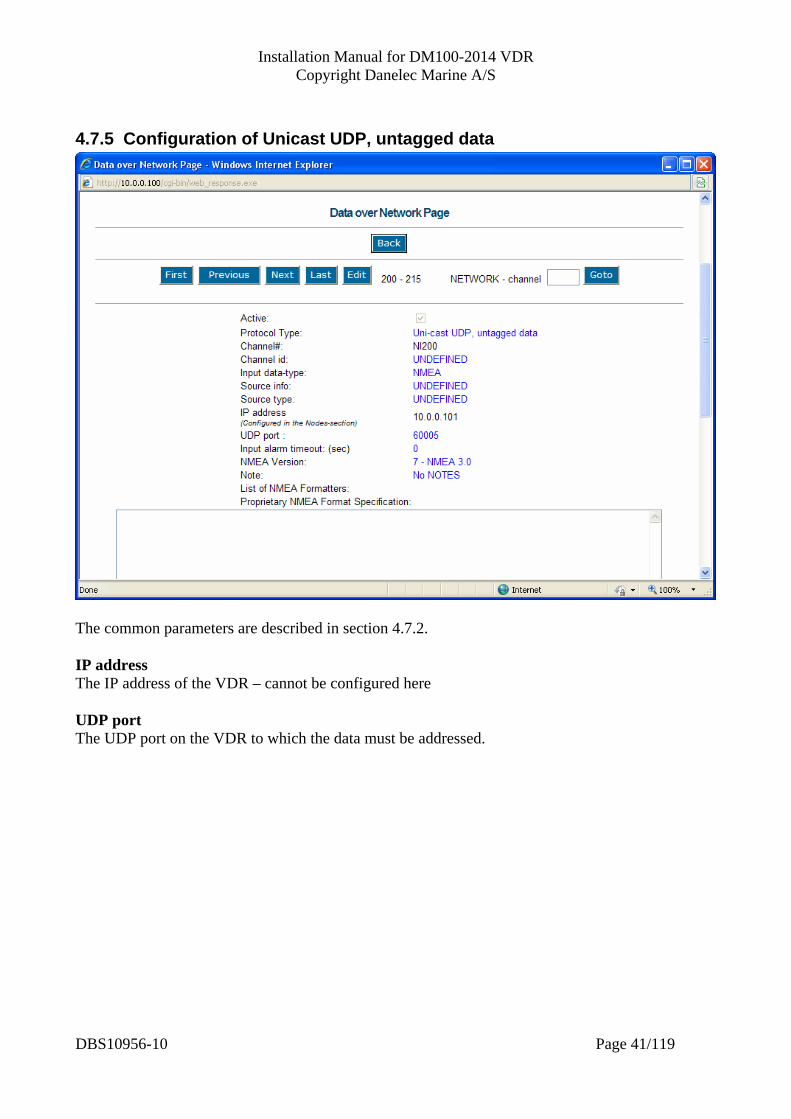
4.7.5 Configuration of Unicast UDP, untagged data
The common parameters are described in section 4.7.2. IP address The IP address of the VDR – cannot be configured here UDP port The UDP port on the VDR to which the data must be addressed.
DBS10956-10 Page 41/119
Installation Manual for DM100-2014 VDR Copyright Danelec Marine A/S
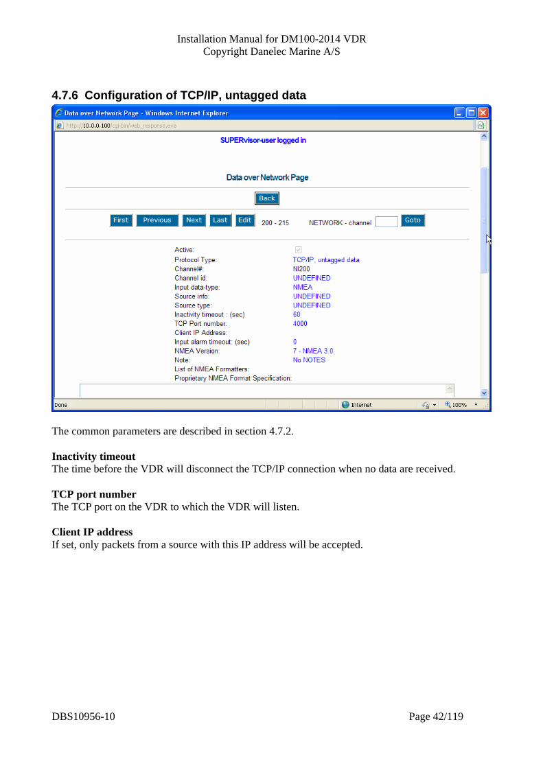
4.7.6 Configuration of TCP/IP, untagged data
The common parameters are described in section 4.7.2. Inactivity timeout The time before the VDR will disconnect the TCP/IP connection when no data are received. TCP port number The TCP port on the VDR to which the VDR will listen. Client IP address If set, only packets from a source with this IP address will be accepted.
DBS10956-10 Page 42/119
Installation Manual for DM100-2014 VDR Copyright Danelec Marine A/S
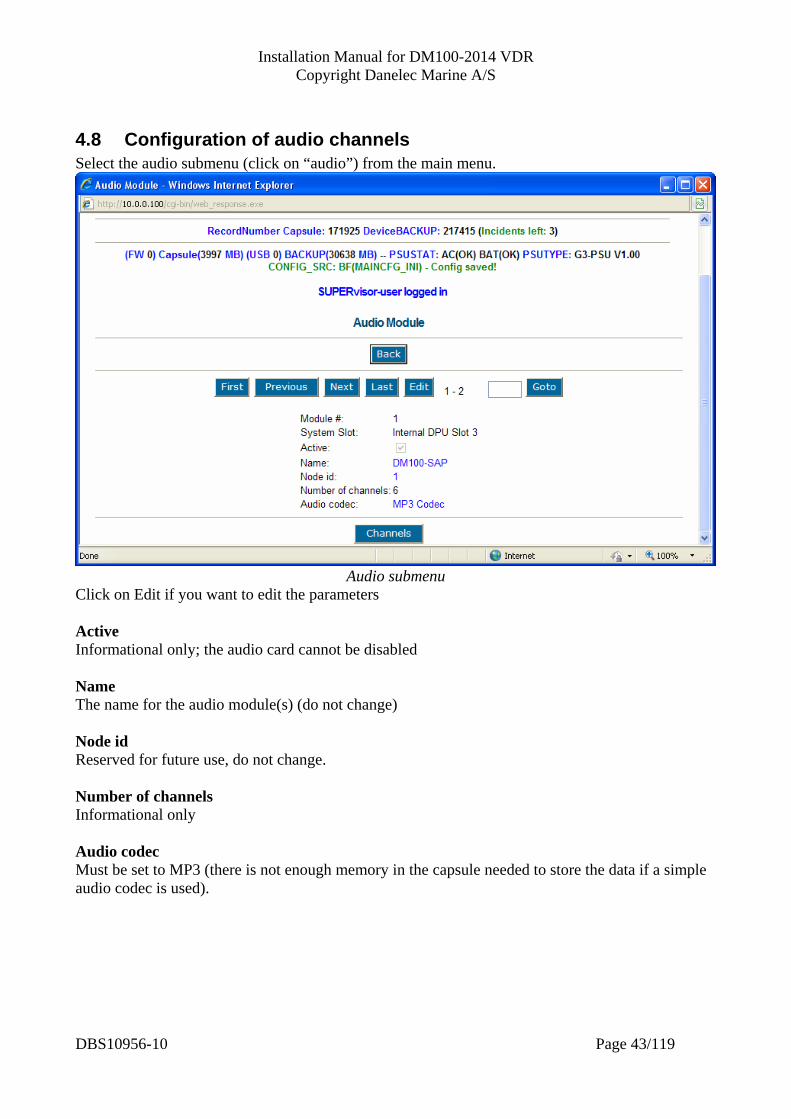
4.8 Configuration of audio channels Select the audio submenu (click on “audio”) from the main menu.
Audio submenu
Click on Edit if you want to edit the parameters Active Informational only; the audio card cannot be disabled Name The name for the audio module(s) (do not change) Node id Reserved for future use, do not change. Number of channels Informational only Audio codec Must be set to MP3 (there is not enough memory in the capsule needed to store the data if a simple audio codec is used).
DBS10956-10 Page 43/119
Installation Manual for DM100-2014 VDR Copyright Danelec Marine A/S
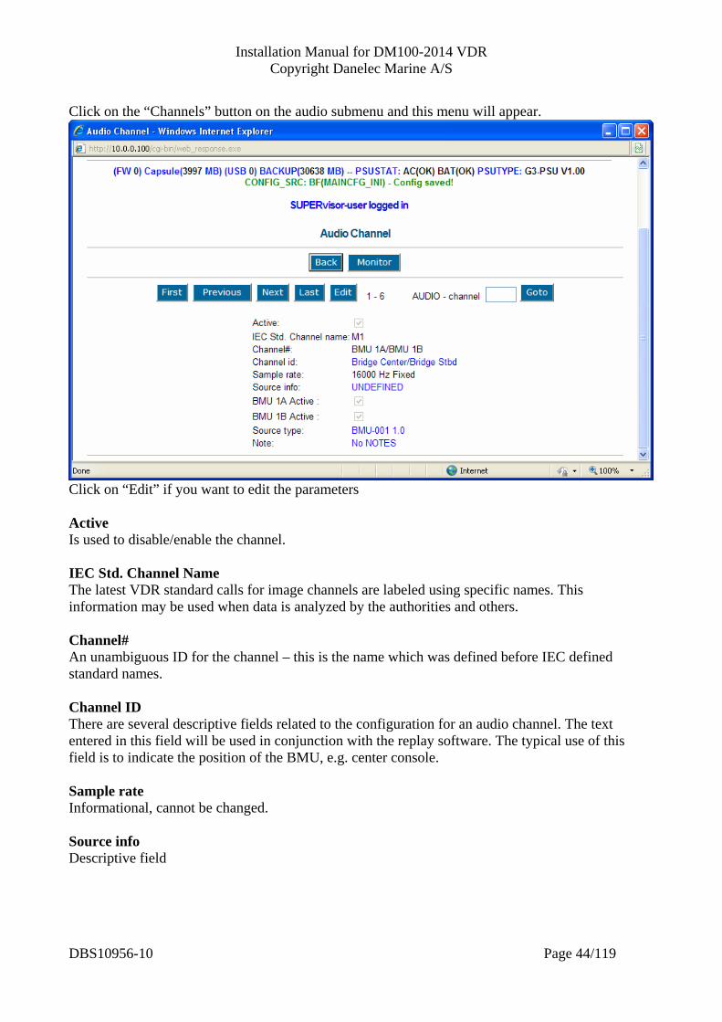
Click on the “Channels” button on the audio submenu and this menu will appear.
Click on “Edit” if you want to edit the parameters Active Is used to disable/enable the channel. IEC Std. Channel Name The latest VDR standard calls for image channels are labeled using specific names. This information may be used when data is analyzed by the authorities and others. Channel# An unambiguous ID for the channel – this is the name which was defined before IEC defined standard names. Channel ID There are several descriptive fields related to the configuration for an audio channel. The text entered in this field will be used in conjunction with the replay software. The typical use of this field is to indicate the position of the BMU, e.g. center console. Sample rate Informational, cannot be changed. Source info Descriptive field
DBS10956-10 Page 44/119
Installation Manual for DM100-2014 VDR Copyright Danelec Marine A/S
Source type Descriptive field, the type ID for the BMU is currently “BMU-001 1.0” for the indoor model and “BMU-002 1.0” for the outdoor model BMU nA Active (n = 1,2,3, or 4 depending of channel). This will enable the microphone test for the microphone. BMU nB Active (n = 1,2, or 3 depending of channel) This will enable the microphone test for the microphone. Note Optional informational text.
DBS10956-10 Page 45/119

Installation Manual for DM100-2014 VDR Copyright Danelec Marine A/S
4.8.1 Test of audio Click on the “Monitor” button and the audio test tool will appear.
Audio level monitor: The audio level monitor at the bottom of the page shows the current audio level for the BMUs. The VDR is able to record up till level 1023. The level must be well below 1023 when a normal conversation is taking place near a BMU. Test Microphones: Will begin the microphone test. “Recording Start”,” Stop” and “Play” button: A sample of audio (maximum 60 seconds) may be recorded for evaluation.
DBS10956-10 Page 46/119
Installation Manual for DM100-2014 VDR Copyright Danelec Marine A/S
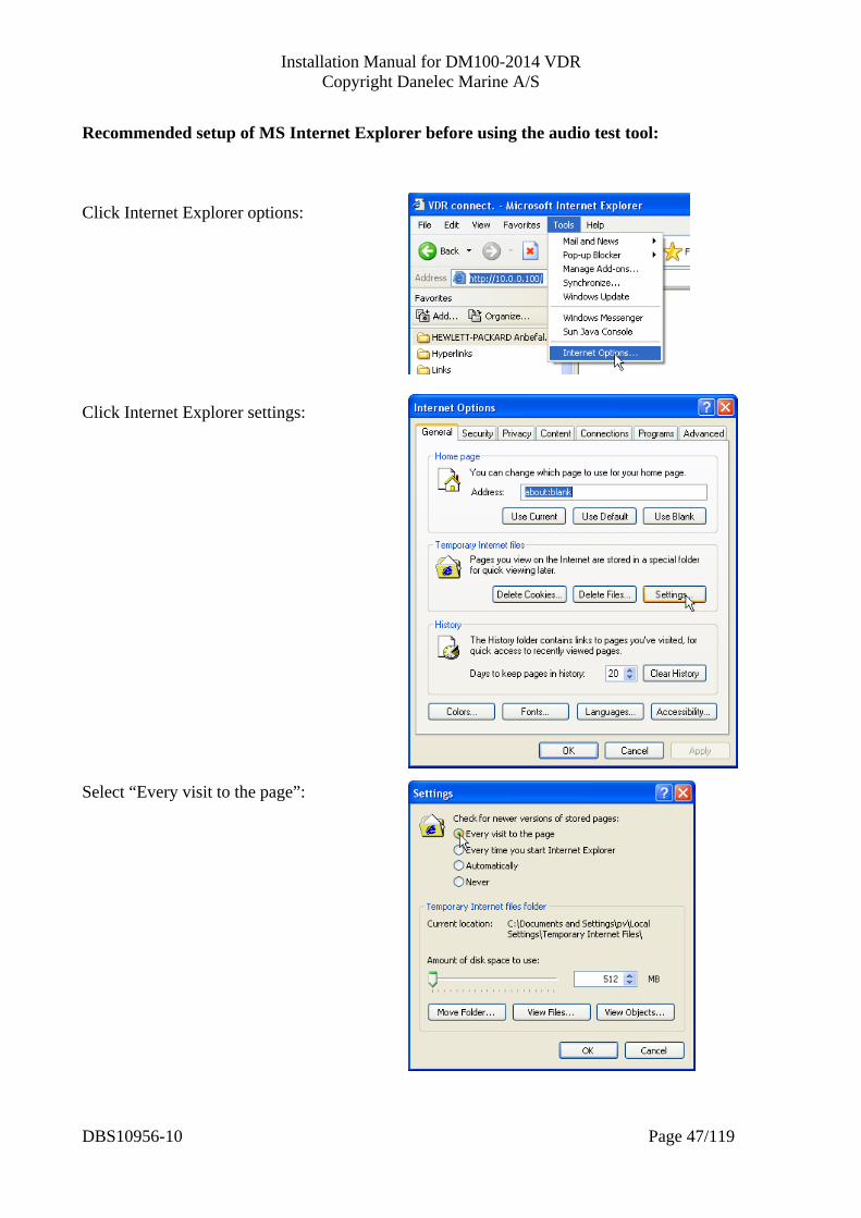
Recommended setup of MS Internet Explorer before using the audio test tool: Click Internet Explorer options: Click Internet Explorer settings: Select “Every visit to the page”:
DBS10956-10 Page 47/119

Installation Manual for DM100-2014 VDR Copyright Danelec Marine A/S
4.9 Configuration of image channels Select the image submenu from the main menu.
Video submenu
The table on this page shows how the eight channels for recording images are configured. The VDR is per default configured to receive all image data using Ethernet and IEC 61162-450. Remote video interfaces may be utilized for capturing video for equipment which cannot send images using IEC61162-450.
4.9.1 Configuration of image channels Click on the “Channel” button and the configuration page for the image channels will appear. The page for each image channel will look different depending on the settings for “Image input type”: For configuration of analog video input, see section 4.9.5 For configuration of digital video input, see section 4.9.10 For configuration of input of images over Ethernet, see section 4.9.4
DBS10956-10 Page 48/119
Installation Manual for DM100-2014 VDR Copyright Danelec Marine A/S
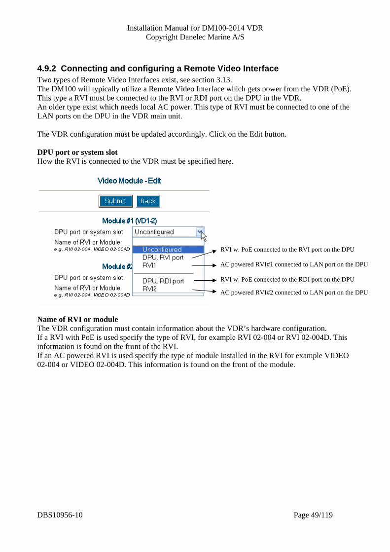
4.9.2 Connecting and configuring a Remote Video Interface Two types of Remote Video Interfaces exist, see section 3.13. The DM100 will typically utilize a Remote Video Interface which gets power from the VDR (PoE). This type a RVI must be connected to the RVI or RDI port on the DPU in the VDR. An older type exist which needs local AC power. This type of RVI must be connected to one of the LAN ports on the DPU in the VDR main unit. The VDR configuration must be updated accordingly. Click on the Edit button. DPU port or system slot How the RVI is connected to the VDR must be specified here.
AC powered RVI#1 connected to LAN port on the DPU
RVI w. PoE connected to the RVI port on the DPU
AC powered RVI#2 connected to LAN port on the DPU
RVI w. PoE connected to the RDI port on the DPU
Name of RVI or module The VDR configuration must contain information about the VDR’s hardware configuration. If a RVI with PoE is used specify the type of RVI, for example RVI 02-004 or RVI 02-004D. This information is found on the front of the RVI. If an AC powered RVI is used specify the type of module installed in the RVI for example VIDEO 02-004 or VIDEO 02-004D. This information is found on the front of the module.
DBS10956-10 Page 49/119
Installation Manual for DM100-2014 VDR Copyright Danelec Marine A/S
4.9.3 Description of common parameters for a image channel
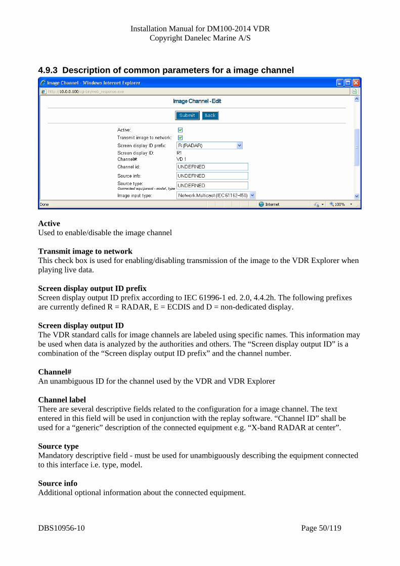
Active Used to enable/disable the image channel Transmit image to network This check box is used for enabling/disabling transmission of the image to the VDR Explorer when playing live data. Screen display output ID prefix Screen display output ID prefix according to IEC 61996-1 ed. 2.0, 4.4.2h. The following prefixes are currently defined R = RADAR, E = ECDIS and D = non-dedicated display. Screen display output ID The VDR standard calls for image channels are labeled using specific names. This information may be used when data is analyzed by the authorities and others. The “Screen display output ID” is a combination of the “Screen display output ID prefix” and the channel number. Channel# An unambiguous ID for the channel used by the VDR and VDR Explorer Channel label There are several descriptive fields related to the configuration for a image channel. The text entered in this field will be used in conjunction with the replay software. “Channel ID” shall be used for a “generic” description of the connected equipment e.g. “X-band RADAR at center”. Source type Mandatory descriptive field - must be used for unambiguously describing the equipment connected to this interface i.e. type, model. Source info Additional optional information about the connected equipment.
DBS10956-10 Page 50/119

Installation Manual for DM100-2014 VDR Copyright Danelec Marine A/S
Image input Type Used to specify from which type of input the images are acquired. “Submit” must be pressed after this parameter is changed. The layout of the configuration page may change if input type is changed.
DBS10956-10 Page 51/119
Installation Manual for DM100-2014 VDR Copyright Danelec Marine A/S
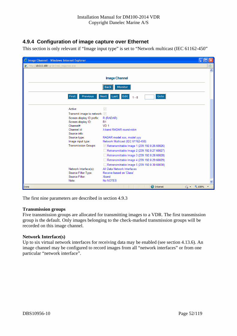
4.9.4 Configuration of image capture over Ethernet This section is only relevant if “Image input type” is set to “Network multicast (IEC 61162-450”
The first nine parameters are described in section 4.9.3 Transmission groups Five transmission groups are allocated for transmitting images to a VDR. The first transmission group is the default. Only images belonging to the check-marked transmission groups will be recorded on this image channel. Network Interface(s) Up to six virtual network interfaces for receiving data may be enabled (see section 4.13.6). An image channel may be configured to record images from all “network interfaces” or from one particular “network interface”.
DBS10956-10 Page 52/119
Installation Manual for DM100-2014 VDR Copyright Danelec Marine A/S
Source filter type: IEC 61996-1 ed2.0 takes into account that multi functional workstations may be in use. Consult IEC 61996-1 ed2.0 Annex E and F. Receive based on source: Only images belonging to a specific class will be recorded on this images channel, for example the images from all workstation showing S-band RADAR data. The name of the class must be specified in “Source Filter”. A VDR must record minimum four classes of images: Sband, Xband, ECDIS.1 and ECDIS.2 i.e. minimum four image channels must be utilized. Receive based on location: Only images from a specific workstation (location) will be recorded on this image channel. “Location” must be specified in “Source Filter”. Source filter: See “Source filter type”.
DBS10956-10 Page 53/119

Installation Manual for DM100-2014 VDR Copyright Danelec Marine A/S
4.9.5 Configuration of analog video The section is only relevant if a Remote Video Interface supporting analog input is utilized for acquiring the image and if “Image input type” is set to “Analog”. Only the first 4 image channels can be configured for this.
Select a channel and click “Edit” if you want to edit the parameters for an image channel. The first nine parameters are described in section 4.9.3
DBS10956-10 Page 54/119
Installation Manual for DM100-2014 VDR Copyright Danelec Marine A/S
Image format The VDR can save the acquired images in two formats, indexed PNG or compressed TIFF. In general indexed PNG is the best choice for computer generated images. Radar model A database with parameters for known radars is available. This field displays which radar type the original parameters were derived from. The “Verify Radar-database” button This button is used to compare the actual entered data with original data stored in the database for the selected radar model. Horizontal offset Used to shift the image left (higher value) and right (lower value). Vertical offset Used to shift the image up (higher value) and down (lower value). PLL multiplier Determines the horizontal size of the image (larger value –> larger image). Horizontal sync polarity Must be set to what is specified for the radar. Phase “Phase” is used to align the time of sampling with the center of the pixels. Must be adjusted correctly (experimental) to enhance the sharpness of the image. Horizontal and vertical resolution Must be set to what is specified for the radar.
DBS10956-10 Page 55/119

Installation Manual for DM100-2014 VDR Copyright Danelec Marine A/S
VCO range The VCO range is normally determined from the other parameters. The VCO range must match the horizontal pixel clock. The hardware will be unable to capture images if the VCO range is wrong. Non-interlaced: Standard Resolution Refresh Rate
(Hz) Horizontal Frequency (kHz)
Pixel Rate (MHz) VCO range
VGA 640 x 480 60 72 75 85
31.5 37.7 37.5 43.3
25.175 31.500 31.500 36.000
1 2 2 4
SVGA 800 x 600 56 60 72 75 85
35.1 37.9 48.1 46.9 53.7
36.000 40.000 50.000 49.500 56.250
4 6 7 8 9
XGA 1024 x 768 60 70 75 80 85
48.4 56.5 60.0 64.0 68.3
65.000 75.000 78.750 85.500 94.500
10 11 12 13 14
SXGA 1280 x 1024 60 75 85
64.0 80.0 91.1
108.000 135.000 157.500
15 16 17
UXGA 1600 x 1200 60 65 70 75
75.0 81.3 87.5 93.8
162.000 175.500 189.000 202.500
18 19 20 21
1920 x 1080 60 67.1 172.800 19 1920 x 1200 60 74.7 193.200 20 For interlaced video where only resolution and field frequency* are known, find pixel rate using this table and divide it by 2. Use this number to determine the VCO range. E.g. 1024x768, field frequency = 75Hz. Pixel rate from table +78.750 ≈ 80.000/2 = 40.000 ⇒ VCO range = 6. * Combined frequency for even and odd fields, which is also equal to vertical sync frequency. The vertical sync frequency is one of the data items in the front-end data (see section 4.9.6). Color mask Determines how many different colors are recognized. If “Image format” is set to PNG: “Color mask” has normally little influence on how well the image compresses if “Image format” is set to PNG. Set “Color mask” to 24 bit if “Image format” is set to PNG. If “Image format” is set to TIFF: “Color mask” should be set to match the color depth of the RADAR or ECDIS. Too many bits will make the image compression ineffective and may cause data overflow in the capsule (error codes 88-94). Most equipment work fine with 9 bits.
DBS10956-10 Page 56/119
Installation Manual for DM100-2014 VDR Copyright Danelec Marine A/S
Contrast RGB Used for changing the contrast of the captured radar images. A higher value will decrease the contrast of the image. The value 127 corresponds to a signal level equal to 0,75V which most commonly used signal level. Brilliance RGB Used for changing the brilliance of the captured radar images. A higher value will decrease the brilliance of the image. The value 127 corresponds to the black level at 0V which most commonly used black level. Note Optional informative text.
DBS10956-10 Page 57/119
Installation Manual for DM100-2014 VDR Copyright Danelec Marine A/S
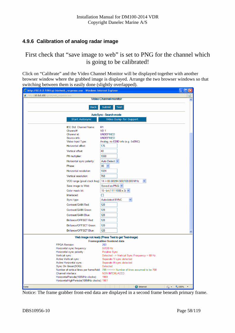
4.9.6 Calibration of analog radar image First check that “save image to web” is set to PNG for the channel which
is going to be calibrated! Click on “Calibrate” and the Video Channel Monitor will be displayed together with another browser window where the grabbed image is displayed. Arrange the two browser windows so that switching between them is easily done (slightly overlapped).
Notice: The frame grabber front-end data are displayed in a second frame beneath primary frame.
DBS10956-10 Page 58/119
Installation Manual for DM100-2014 VDR Copyright Danelec Marine A/S
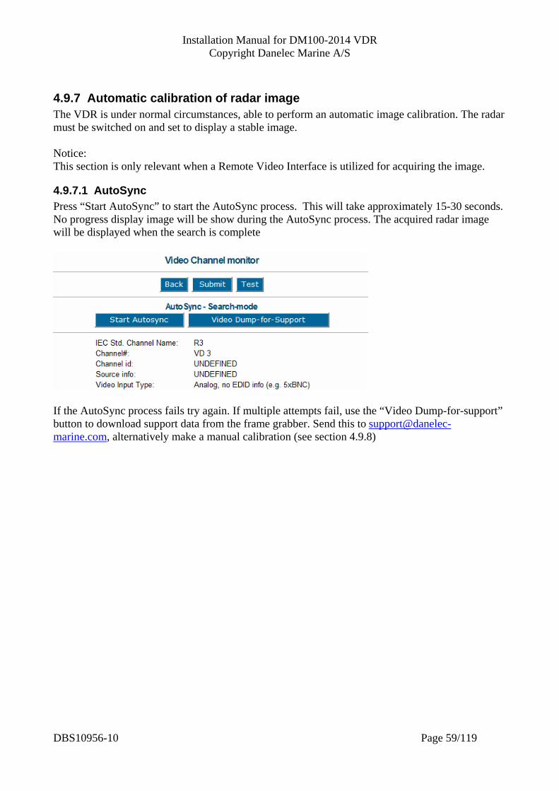
4.9.7 Automatic calibration of radar image The VDR is under normal circumstances, able to perform an automatic image calibration. The radar must be switched on and set to display a stable image. Notice: This section is only relevant when a Remote Video Interface is utilized for acquiring the image.
4.9.7.1 AutoSync Press “Start AutoSync” to start the AutoSync process. This will take approximately 15-30 seconds. No progress display image will be show during the AutoSync process. The acquired radar image will be displayed when the search is complete
If the AutoSync process fails try again. If multiple attempts fail, use the “Video Dump-for-support” button to download support data from the frame grabber. Send this to [email protected], alternatively make a manual calibration (see section 4.9.8)
DBS10956-10 Page 59/119
Installation Manual for DM100-2014 VDR Copyright Danelec Marine A/S
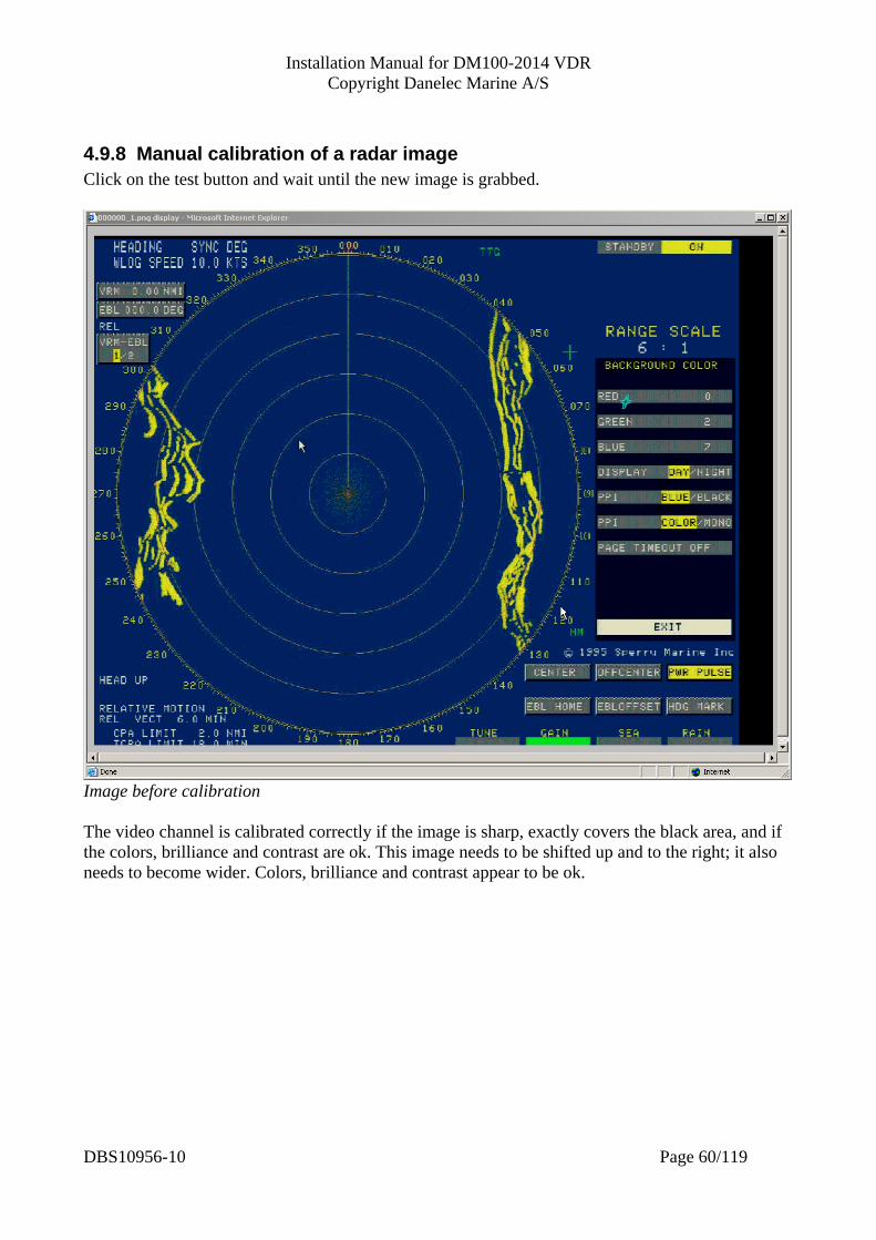
4.9.8 Manual calibration of a radar image Click on the test button and wait until the new image is grabbed.
Image before calibration The video channel is calibrated correctly if the image is sharp, exactly covers the black area, and if the colors, brilliance and contrast are ok. This image needs to be shifted up and to the right; it also needs to become wider. Colors, brilliance and contrast appear to be ok.
DBS10956-10 Page 60/119

Installation Manual for DM100-2014 VDR Copyright Danelec Marine A/S
Image after calibration
Configuration before Configuration after
DBS10956-10 Page 61/119
Installation Manual for DM100-2014 VDR Copyright Danelec Marine A/S
If the image already covers the black area at the beginning of the calibration process then it might already fit. Shift the image slightly to the left by increasing the value for horizontal offset by one, and check that a black vertical line appears to the right of the image Shift the image slightly to the right by decreasing the value for horizontal offset by two (one from the original value) and check that a black vertical line appears to the left of the image. The image fits the black area if both black lines appear; remember to revert to the original value for horizontal offset. If the above test reveals that the image is too large then it must be made smaller by decreasing the value for the PLL multiplier.
4.9.9 Hints for calibrating an unknown radar Use as much information as possible from the “frame grabber front-end data”. Set horizontal and vertical offset to low values. Try different values for PLL multiplier until a stable image appears.
DBS10956-10 Page 62/119
Installation Manual for DM100-2014 VDR Copyright Danelec Marine A/S
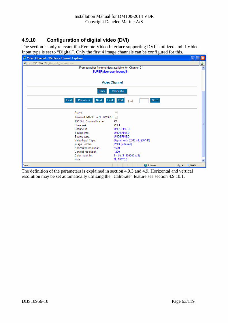
4.9.10 Configuration of digital video (DVI) The section is only relevant if a Remote Video Interface supporting DVI is utilized and if Video Input type is set to “Digital”. Only the first 4 image channels can be configured for this.
The definition of the parameters is explained in section 4.9.3 and 4.9. Horizontal and vertical resolution may be set automatically utilizing the “Calibrate” feature see section 4.9.10.1.
DBS10956-10 Page 63/119
Installation Manual for DM100-2014 VDR Copyright Danelec Marine A/S
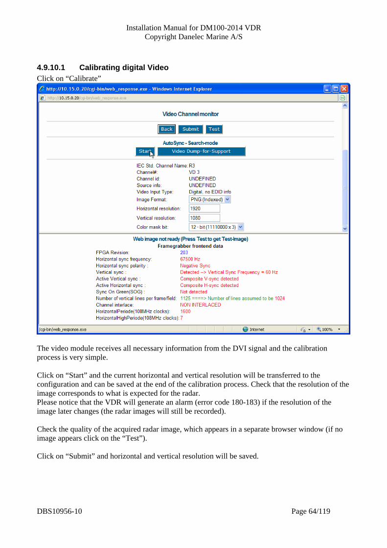
4.9.10.1 Calibrating digital Video Click on “Calibrate”
The video module receives all necessary information from the DVI signal and the calibration process is very simple. Click on “Start” and the current horizontal and vertical resolution will be transferred to the configuration and can be saved at the end of the calibration process. Check that the resolution of the image corresponds to what is expected for the radar. Please notice that the VDR will generate an alarm (error code 180-183) if the resolution of the image later changes (the radar images will still be recorded). Check the quality of the acquired radar image, which appears in a separate browser window (if no image appears click on the “Test”). Click on “Submit” and horizontal and vertical resolution will be saved.
DBS10956-10 Page 64/119
Installation Manual for DM100-2014 VDR Copyright Danelec Marine A/S
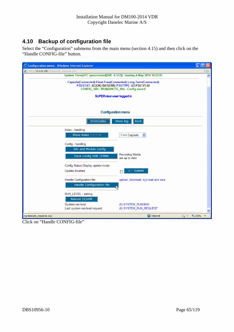
4.10 Backup of configuration file Select the “Configuration” submenu from the main menu (section 4.15) and then click on the “Handle CONFIG-file” button.
Click on “Handle CONFIG-file”
DBS10956-10 Page 65/119
Installation Manual for DM100-2014 VDR Copyright Danelec Marine A/S
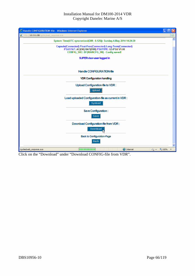
Click on the “Download” under “Download CONFIG-file from VDR”.
DBS10956-10 Page 66/119

Installation Manual for DM100-2014 VDR Copyright Danelec Marine A/S
The browser will respond with a dialog box depending on your browser, operating system and security settings.
Click on save.
Select a suitable folder and give the file an unambiguous name, do not overwrite the file extension (.ini). Click on save. How to restore a backup file is described in section 4.15
DBS10956-10 Page 67/119
Installation Manual for DM100-2014 VDR Copyright Danelec Marine A/S
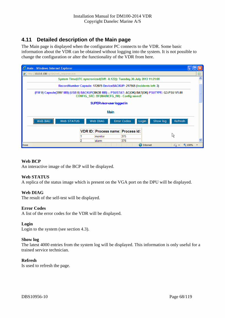
4.11 Detailed description of the Main page The Main page is displayed when the configurator PC connects to the VDR. Some basic information about the VDR can be obtained without logging into the system. It is not possible to change the configuration or alter the functionality of the VDR from here.
Web BCP An interactive image of the BCP will be displayed. Web STATUS A replica of the status image which is present on the VGA port on the DPU will be displayed. Web DIAG The result of the self-test will be displayed. Error Codes A list of the error codes for the VDR will be displayed. Login Login to the system (see section 4.3). Show log The latest 4000 entries from the system log will be displayed. This information is only useful for a trained service technician. Refresh Is used to refresh the page.
DBS10956-10 Page 68/119
Installation Manual for DM100-2014 VDR Copyright Danelec Marine A/S
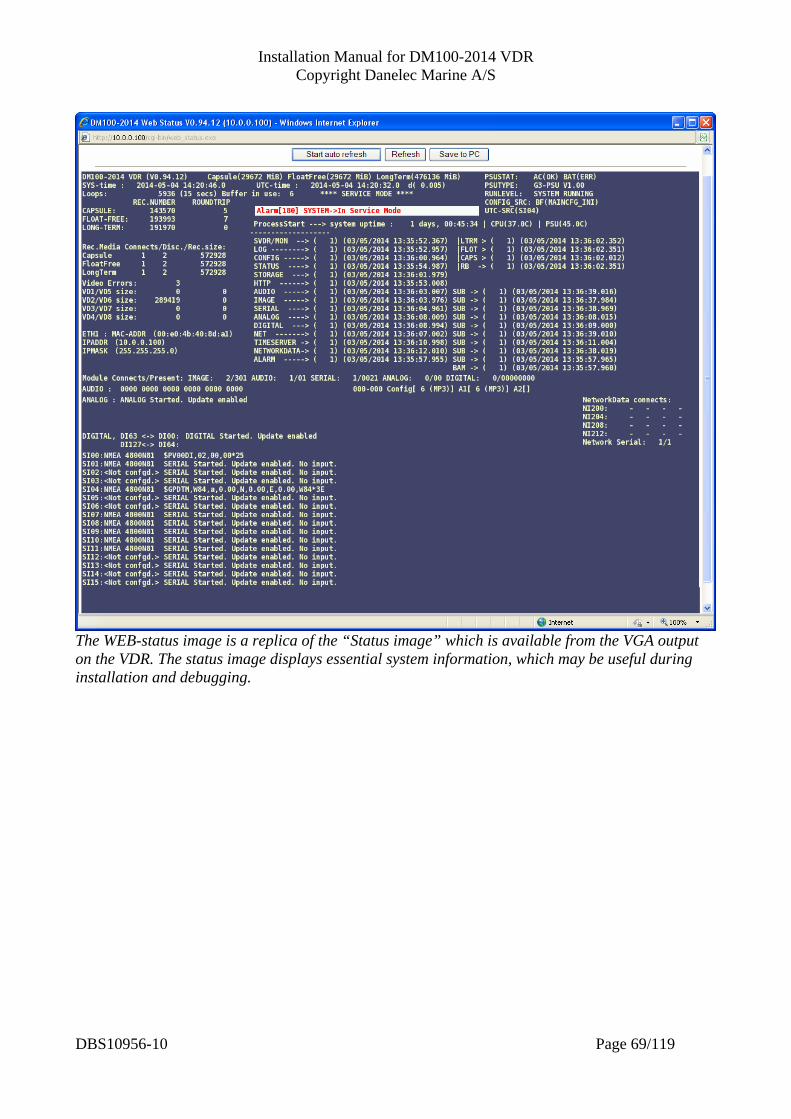
The WEB-status image is a replica of the “Status image” which is available from the VGA output on the VDR. The status image displays essential system information, which may be useful during installation and debugging.
DBS10956-10 Page 69/119

Installation Manual for DM100-2014 VDR Copyright Danelec Marine A/S
4.12 System Info Submenu Select the System Info submenu from the main menu and this page will appear.
This page contains information about the software and cannot be edited.
DBS10956-10 Page 70/119

Installation Manual for DM100-2014 VDR Copyright Danelec Marine A/S
DBS10956-10 Page 71/119
4.13 Node configuration page Select the Nodes submenu from the main menu and this page will appear

Installation Manual for DM100-2014 VDR Copyright Danelec Marine A/S
4.13.1 Liveplay configuration “Enable multicast for Liveplay” must be enabled if the VDR shall send live data simultaneous to multiple replay stations. .
4.13.2 Ethernet capsule settings The IP addresses for the two capsules are shown here – cannot be changed
4.13.3 IEC61162-450 settings The system function ID for the VDR should not be changed (is set according to the standard). However, optionally the SFI for recording images and networks data may be configured to not have the same value.
4.13.4 Bridge Alert management Interface If enabled, the VDR is able to communicate with a Bridge Alarm Management system according to IEC 91924 The VDR can either communicate with a Bridge Alarm Management system using serial interface SI11/SO11 or Ethernet.
4.13.5 Network processor syslog As required by the IEC 61162-450 standard the VDR is able to send syslog messages related the IEC 61162-450 communication. See section 7 for details.
4.13.6 Configuration of network interfaces It is possible to configure up to seven virtual network interfaces for the VDR. The “Configuration/VDR data” network interface is used for accessing the VDR’s configuration interface and is the “VDR data Interface” to be used by the investigate authorities. A label clearly showing the new IP address must be attached inside the door of the VDR main unit (the DAU) if the IP address is changed for the “VDR configuration/data interface”. The remaining six network interfaces may be used for capturing data sent to the VDR over Ethernet typically according to IEC 61162-450. An IP address and minimum one LAN port must be allocated for a network interface. The default configuration is a single “data capture interface” with six LAN ports alocated. Please notice that the VDR will never switch or route data from one LAN port to another.
DBS10956-10 Page 72/119
Installation Manual for DM100-2014 VDR Copyright Danelec Marine A/S
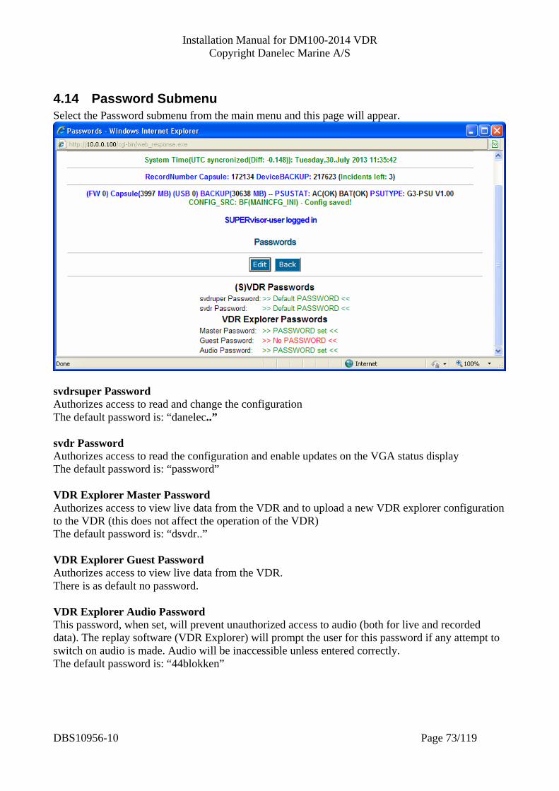
4.14 Password Submenu Select the Password submenu from the main menu and this page will appear.
svdrsuper Password Authorizes access to read and change the configuration The default password is: “danelec..” svdr Password Authorizes access to read the configuration and enable updates on the VGA status display The default password is: “password” VDR Explorer Master Password Authorizes access to view live data from the VDR and to upload a new VDR explorer configuration to the VDR (this does not affect the operation of the VDR) The default password is: “dsvdr..” VDR Explorer Guest Password Authorizes access to view live data from the VDR. There is as default no password. VDR Explorer Audio Password This password, when set, will prevent unauthorized access to audio (both for live and recorded data). The replay software (VDR Explorer) will prompt the user for this password if any attempt to switch on audio is made. Audio will be inaccessible unless entered correctly. The default password is: “44blokken”
DBS10956-10 Page 73/119

Installation Manual for DM100-2014 VDR Copyright Danelec Marine A/S
4.15 Configuration submenu
Show index The index of the selected drive will be displayed. This information is only useful for a trained service technician. SIU and Module config The location of the modules will be displayed. A tool for including and removing a SIU to/from to configuration is will be displayed. Consult the installation manual for the SIU. Save VDR config -> FRM Configuration changes are normally not save til the FRM until service mode is exited, the operators logs out or after inactivity timeout (10 minutes). A click on this button will force the VDR to save the configuration changes immediately. Handle config file This function is used for making or restoring a backup file of the VDR configuration. Consult section 4.15.1. Reboot (S)VDR A click on this button will reboot the system.
DBS10956-10 Page 74/119

Installation Manual for DM100-2014 VDR Copyright Danelec Marine A/S
4.15.1 Handle CONFIG-file
Upload CONFIG-file to SVDR This function may be used for uploading a previously stored backup of the configuration. How to make the backup file is described in section 4.10. The file will just be uploaded into memory and will not have any effect until a “sysload” is executed. Load uploaded CONFIG-file as current (configuration) in SVDR This function will force the system to use the uploaded backup configuration. The original configuration will NOT be lost until a “save configuration” or any submit is executed. If you don’t want to use the new configuration then restart the system. Save Configuration The uploaded backup configuration will be stored permanently and the original configuration will be lost. Download configuration from VDR This is the recommended and secure procedure for making a backup of the configuration. Consult section 4.10 for details.
DBS10956-10 Page 75/119

Installation Manual for DM100-2014 VDR Copyright Danelec Marine A/S
4.16 Tech support submenu Select the “Tech support” Submenu from the main menu and this page will appear
Show log The latest 4000 entries from the system log will be displayed. This information is only useful for a trained service technician. Image receive log A log which contains information about the images received from the network (IEC 61162-450). Web PCB An interactive image of the PCB. Web STATUS A replica of the status image which is present on the VGA port on the DPU will be displayed. NetworkData A list of the statistical counters related to IEC 61162-450 see section 7 for details. Error Codes A list of the error codes for the VDR will be displayed. Dump for Support “Dump for Support” is a feature which generate a file containing information from the VDR which can be used for troubleshooting primarily by Danelec.
DBS10956-10 Page 76/119

Installation Manual for DM100-2014 VDR Copyright Danelec Marine A/S
5 Verification of installation and configuration The APT tool must be used to verify the installation and configuration. The APT tool will generate a report which may be useful for documenting that the VDR was installed and configured properly. The data captured by the APT tool must be sent to Danelec, who will issue an IPT certificate (or if requested an APT certificate which is typically needed following a retrofit).
DBS10956-10 Page 77/119
Installation Manual for DM100-2014 VDR Copyright Danelec Marine A/S
6 Detailed specification of the IEC 61162-450 interface
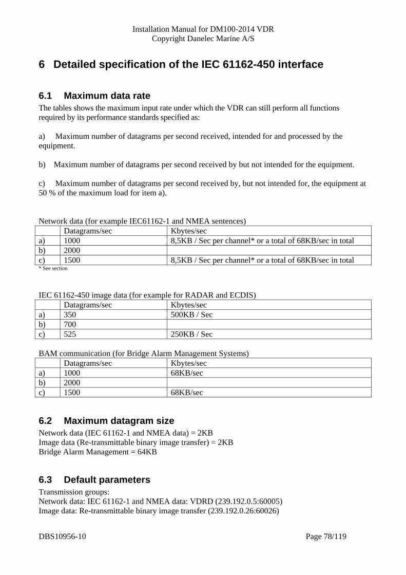
6.1 Maximum data rate The tables shows the maximum input rate under which the VDR can still perform all functions required by its performance standards specified as: a) Maximum number of datagrams per second received, intended for and processed by the equipment. b) Maximum number of datagrams per second received by but not intended for the equipment. c) Maximum number of datagrams per second received by, but not intended for, the equipment at 50 % of the maximum load for item a). Network data (for example IEC61162-1 and NMEA sentences) Datagrams/sec Kbytes/sec a) 1000 8,5KB / Sec per channel* or a total of 68KB/sec in total b) 2000 c) 1500 8,5KB / Sec per channel* or a total of 68KB/sec in total * See section IEC 61162-450 image data (for example for RADAR and ECDIS) Datagrams/sec Kbytes/sec a) 350 500KB / Sec b) 700 c) 525 250KB / Sec BAM communication (for Bridge Alarm Management Systems) Datagrams/sec Kbytes/sec a) 1000 68KB/sec b) 2000 c) 1500 68KB/sec
6.2 Maximum datagram size Network data (IEC 61162-1 and NMEA data) = 2KB Image data (Re-transmittable binary image transfer) = 2KB Bridge Alarm Management = 64KB
6.3 Default parameters Transmission groups: Network data: IEC 61162-1 and NMEA data: VDRD (239.192.0.5:60005) Image data: Re-transmittable binary image transfer (239.192.0.26:60026)
DBS10956-10 Page 78/119

Installation Manual for DM100-2014 VDR Copyright Danelec Marine A/S
BAM: MISC (239.192.0.1:60001) Default SFI = VR0001 Default IP address for data: 172.16.8.2
6.4 Syslog destination address Multicast address 239.192.0.254, port 514
6.5 Supported transmission groups Network data: VDRD (239.192.0.5:60005) Re-transmittable binary image transfer (239.192.0.26:60026) - (239.192.0.30:60030) Bridge Alarm Management: MISC (239.192.0.1:60001)
6.6 Handling of tag block parameters g - Group control – Used to group a number of Lines together.
Grouping is supported when receiving Network Data (IEC61162-1/NMEA), and BAM messages. Grouping is added to BAM output. (IEC61162-450 only)
s -Source Identification – The Source SFI
Network Data: The Source SFI is used for sorting the input data into network channels (NI200-NI215). Only the last source identification in a tag-block is used. If the source SFI does not match any configured channels the sentence is not recorded. BAM: The Source SFI must match what is specified in the VDR configuration.
d – Destination identification – The destination SFI
Network Data: If destination SFI(s) present one destination SFIs must match the SFI (for receipt of Network Data) of the VDR in order for the sentence to be recorded. If no destination SFI is present the sentence will be recorded. BAM: If destination SFI(s) present one destination SFIs must match the SFI (for bridge alarm management) of the VDR in order for the sentence to be processed. If no destination SFI is present the sentence will be processed.
n – Line-count parameter – Sentence sequence counter Network Data: This parameter is ignored BAM: This parameter is ignored
t - Text string parameter – Proprietary data
Network Data: This parameter is ignored BAM: This parameter is ignored
DBS10956-10 Page 79/119
Installation Manual for DM100-2014 VDR Copyright Danelec Marine A/S
6.7 Recording Network data: Data are sorted into channels based on the source SFI, and filtered based on destination SFI if present i.e. one destination SFI must match the SFI (for receipt of Network Data) of the VDR. Image data: Image data are recorded based on class or location. If images from multiple locations within the same class are received the images may be recorded round-robin on one track depending of the configuration. All images from one location may be recorded on one track depending of the configuration. One image may be recorded on several tracks depending of the configuration. .
6.8 Supported sentences (IEC61162-1/NMEA) Network Data: Receive: Any Transmit: N/A, the VDR does not transmit network data Bridge alarm management (BAM) Receive: HBT, ACM Transmit: HBT, ALC, ARF
DBS10956-10 Page 80/119
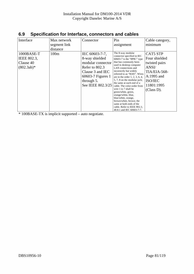
Installation Manual for DM100-2014 VDR Copyright Danelec Marine A/S
6.9 Specification for Interface, connectors and cables Interface Max network
segment link distance
Connector Pin assignment
Cable category, minimum
1000BASE-T IEEE 802.3, Clause 40 (802.3ab)*
100m IEC 60603-7-7, 8-way shielded modular connectorRefer to 802.3 Clause 3 and IEC 60603-7 Figures 1 through 5. See IEEE 802.3/25
The 8-way modular connector specified in IEC 60603-7 is the “8P8C” type that has commonly been used in desktop computer LAN connections and incorrectly but widely referred to as “RJ45”. Wires are in the order 1, 2, 3, 6, 4, 5, 7, 8 on the modular jack; the same at each end of a cable. The color-order from wire 1 to 7 shall be green/white, green, orange/white, blue, blue/white, orange, brown/white, brown; the same at both ends of the cable. Refer to IEEE 802.3, 40.8.1 and IEC 60603-7-7.
CAT5 STP Four shielded twisted pairs ANSI/ TIA/EIA-568-A:1995 and ISO/IEC 11801:1995 (Class D).
* 100BASE-TX is implicit supported – auto negotiate.
DBS10956-10 Page 81/119
Installation Manual for DM100-2014 VDR Copyright Danelec Marine A/S
7 Statistical counters related to IEC 61162-450 A number of error/traffic counters are implemented which are useful for managing the system and for troubleshooting. The counters may be displayed utilizing the BCP or the configuration interface on the VDR (Tech Support -> NetworkData). The following references are used in this section [1] International Standard IEC 61162-450 Ed. 1.0
Maritime navigation and radiocommunication equipment and systems – Digital interfaces – Part 450: Multiple talkers and multiple listeners – Ethernet interconnection
[2] International Standard IEC 61996-1 Ed. 2.0 Maritime navigation and radiocommunication equipment and systems – Shipborne voyage data recorder (VDR) – Part 1: Performance requirements, methods of testing and required test results
[3] International Standard IEC 61162-1 Ed. 4.0 Maritime navigation and radiocommunication equipment and systems – Digital interfaces – Part 1: Single talkers and multiple listeners
7.1 Counters related image capture Header Error “Number of unrecognized headers” Description: The counter for received datagrams with an invalid header as specified in 7.1.1, 7.1.2 and 7.3.9 [1]. Only datagrams with a 61162-450 header with the value of “RrUdP” including a trailing zero are considered a valid datagram for the Image Processor. “RrUdpP” datagrams with a “Message Type” (see 7.3.3.5 [1]) other than DATA or QUERY are also considered invalid. Datagrams with an invalid header are discarded. Syslog: <131> - - 450-NF - 102 - Datagram header error from host: IP-address Where IP-Address is the IP address of the transmitting equipment. Retransmit Request Count “Number of missing datagrams” Description: This counter is incremented each time a retransmit of an image-block if requested by sending an ACK message. This corresponds to the number of missing datagrams error counter specified in 7.3.9 [1]. Syslog: <131> - - 450-VRxxxx - 104 - Missing image datagram Where VRxxxx is the SFI for the VDR Image receiver.
DBS10956-10 Page 82/119
Installation Manual for DM100-2014 VDR Copyright Danelec Marine A/S
Incomplete Images Count “Number of images where errors occurred” Description: This counter is incremented if an image is not completely received before the sender starts sending another image. This corresponds to the number of image blocks where errors occur specified in 7.3.9 [1]. Syslog: <131> - - 450-VRxxxx - 104 - Binary image error Where VRxxxx is the SFI of the VDR Image receiver. Complete Images Count “Total number of images received” Description: This counter is incremented when a complete image is received. Syslog: No syslog message. Duplicate Location Error Count “Number of images from duplicate locations” Description: This counter is incremented if an image is received from different transmitters (based on host IP) but with the same location name. Syslog: <131> - - 450-VRxxxx - 0 - Duplicate location received from multiple hosts: Location Where VRxxxx is the SFI of the VDR Image receiver and Location is the duplicate location received New Location Received Count “Number of images from “New” location” Description: This counter is incremented if an image is received from a location starting with “New”. Syslog: <131> - - 450-VRxxxx - 0 - "New location received: New-Location Where VRxxxx is the SFI of the VDR Image receiver and New-Location is the location received Not Matching Images Count “Number of image which did not match the “filter” of any image channel” Description:
DBS10956-10 Page 83/119

Installation Manual for DM100-2014 VDR Copyright Danelec Marine A/S
This counter is incremented if an image is received but if it could not pass any of the filters configured for the image channels. Syslog: No syslog message. Unsupported Image Formats “Number of images with unsupported format” Description: This counter is incremented if an image is received where the format (mime-type) is not support/understood. Syslog: <131> - - 450-VRxxxx - 0 - " Unsupported Image Format Received: Mime-type Where VRxxxx is the SFI of the VDR Image receiver and Mime-type is the unsupported mime-type.
7.2 Counters related data capture Invalid Header “Number of unrecognized headers” Description: Counter for received datagrams with an invalid header as specified in 7.1.2 [1]. Only datagrams with a 61162-450 header with the value of “UdPbC” including a trailing zero are valid according to 7.1.1 and 6.1 [1]. Datagrams with an invalid header are discarded. Syslog: <131> - - 450-NF - 102 - Datagram header error from host: IP-Address Where IP-Address is the ip address of the transmitting equipment Tag Framing Error “Number of TAG framing errors” Description: Counter for datagrams where a “TAG framing error” (incorrect start or termination of TAG block) is detected when parsing the datagram as specified in 7.2.5 [1]. According to B.2 [1], a tag block is delimited by a back-slash at the start and at the end. The framing error is detected by:
• A received datagram is parsed from left to right. • If the next character is a back-slash, the datagram is searched for a matching back-slash
occurring before the next <CR><LF> or before the end of the datagram. o If a matching back-slash is not found it is considered a tag framing error.
• If the next character was not a back-slash, but the datagram contains a back-slash before the next <CR><LF> or end of the datagram, it is considered a tag-framing error.
DBS10956-10 Page 84/119
Installation Manual for DM100-2014 VDR Copyright Danelec Marine A/S
Datagrams with a tag-framing error are discarded. Syslog: <131> - - 450-VRxxxx - 103 - TAG framing error Where VRxxxx is the SFI of the VDR NMEA/sentence receiver Tag Syntax Error “Number of TAG syntax errors” Description: Counter for datagrams where a “TAG syntax error” (line length, use of delimiters, invalid characters) are detected when parsing the datagram, as specified in 7.2.5 [1]. A tag block is considered to have syntax error if:
• It is longer than 80 characters (excluding the back-slashes) as specified in B.2 [1] • Contains non-valid characters, according the table 1 and table 2 in 8.1 [3].
Datagrams with a tag-syntax error are discarded. Syslog: <131> - - 450-VRxxxx - 103 - TAG syntax error Where VRxxxx is the SFI of the VDR NMEA/sentence receiver Tag Format Error “Number of TAG format errors” Description: Counter for datagrams where “any TAG block formatting error” are detected, as specified in 7.2.5 [1]. This counter is incremented if an error is occurred when parsing the parameter values of a tag block following the format in 7.2.3.1 [1].
• The parser will split the tag-block into parameter entries based on comma delimiter. • The parser will split each parameter entry into a key-value pair delimited by colon. • If the key is not a single letter, it is considered a format error. • If the value for a ‘g’ key does not consists of three integers separated by “-“ it is considered
a format error. Datagrams with a tag-format error are discarded. Syslog: <131> - - 450-VRxxxx - 103 - TAG format error Where VRxxxx is the SFI of the VDR NMEA/sentence receiver Tag Checksum Error “Number of TAG checksum errors”
DBS10956-10 Page 85/119
Installation Manual for DM100-2014 VDR Copyright Danelec Marine A/S
Description: Counter for datagrams where “TAG checksum error” are detected, as specified in 7.2.5 [1]. The checksum is assumed to be the part after the last “*” in the tag-block.
• If the checksum part is missing it is considered a tag checksum error • If the checksum part is not a valid two-digit hex string it is considered a tag checksum error • If the checksum part does not match the calculated checksum value it is considered a tag
checksum error. Datagrams with a tag checksum error are discarded. Syslog: <131> - - 450-VRxxxx - 103 - TAG checksum error Where VRxxxx is the SFI of the VDR NMEA/sentence receiver Not Matching Sentences “Number of sentences not being matched” Description: This counter is incremented if a sentence is received, and there is no channel configured with the corresponding SFI in the “s” field. Syslog: No syslog message. Sentence Syntax Error “Number of sentences with syntax errors” Description: Counter for datagrams where the tag is parsed successfully, but the IEC 61162-1 (NMEA) contents is invalid.
• The 61162-1 sentence includes a checksum field, but it doesn’t match the calculated checksum.
• The 61162-1 sentence contains non-valid characters according the table 1 and table 2 in 8.1 [3].
• The 61162-1 sentence is larger than 82 characters according to 7.3.1 [3]. Datagrams with an invalid 61162-1 sentence are not discarded i.e. the sentence is recorded. Syslog: No syslog message.
DBS10956-10 Page 86/119

Installation Manual for DM100-2014 VDR Copyright Danelec Marine A/S
7.3 Counters related Bridge Alarm Management (BAM) Invalid Header “Number of unrecognized headers” Description: Counter for received datagrams with an invalid header as specified in 7.1.2 [1]. Only datagrams with a 61162-450 header with the value of “UdPbC” including a trailing zero are valid according to 7.1.1 and 6.1 [1]. Datagrams with an invalid header are discarded. Syslog: No syslog supported Tag Framing Error “Number of TAG framing errors” Description: Counter for datagrams where a “TAG framing error” (incorrect start or termination of TAG block) is detected when parsing the datagram as specified in 7.2.5 [1]. According to B.2 [1], a tag block is delimited by a back-slash at the start and at the end. Datagrams with a tag-framing error are discarded. Syslog: No syslog supported Tag Syntax Error “Number of TAG syntax errors” Description: Counter for datagrams where a “TAG syntax error” (line length, use of delimiters, invalid characters) are detected when parsing the datagram, as specified in 7.2.5 [1]. A tag block is considered to have syntax error if:
• It is longer than 80 characters (excluding the back-slashes) as specified in B.2 [1] • Contains non-valid characters, according the table 1 and table 2 in 8.1 [3].
Datagrams with a tag-syntax error are discarded. Syslog: No syslog supported Tag Format Error “Number of TAG format errors” Description: Counter for datagrams where “any TAG block formatting error” are detected, as specified in 7.2.5 [1].
DBS10956-10 Page 87/119
Installation Manual for DM100-2014 VDR Copyright Danelec Marine A/S
This counter is incremented if an error is occurred when parsing the parameter values of a tag block following the format in 7.2.3.1 [1]. Datagrams with a tag-format error are discarded. Syslog: No syslog supported Tag Checksum Error “Number of TAG checksum errors” Description: Counter for datagrams where “TAG checksum error” are detected, as specified in 7.2.5 [1]. The checksum is assumed to be the part after the last “*” in the tag-block.
• If the checksum part is missing it is considered a tag checksum error • If the checksum part is not a valid two-digit hex string it is considered a tag checksum error • If the checksum part does not match the calculated checksum value it is considered a tag
checksum error. Datagrams with a tag checksum error are discarded. Syslog: No syslog supported Sentence Framing Error "Number of sentence framing errors" Description: Counter for datagrams where a “Sentence framing error” (incorrect start or termination of sentence block) is detected when parsing the datagram as specified in 7.2.5 [4]. Datagrams with a sentence checksum error are discarded. Syslog: No syslog supported Sentence Syntax Error “Number of sentences with syntax errors” Description: Counter for datagrams where the tag is parsed successfully, but the IEC 61162-1 (NMEA) contents is invalid.
• The 61162-1 sentence contains non-valid characters according the table 1 and table 2 in 8.1 [3].
DBS10956-10 Page 88/119
Installation Manual for DM100-2014 VDR Copyright Danelec Marine A/S
• The 61162-1 sentence is larger than 82 characters according to 7.3.1 [3]. • Any other 61162-1 sentence syntax errors.
Datagrams with a sentence syntax error are discarded. Syslog: No syslog supported Sentence Checksum Error “Number of sentence checksum errors” Description: Counter for datagrams where “sentence checksum error” are detected, as specified in 7.2.5 [4]. The checksum is assumed to be the part after the last “*” in the tag-block.
• If the checksum part is missing it is considered a sentence checksum error • If the checksum part is not a valid two-digit hex string it is considered a sentence checksum
error • If the checksum part does not match the calculated checksum value it is considered a
sentence checksum error. Datagrams with a sentence checksum error are discarded. Syslog: No syslog supported
DBS10956-10 Page 89/119

Installation Manual for DM100-2014 VDR Copyright Danelec Marine A/S
8 Service and maintenance
8.1 Annual inspection (APT) It is a requirement (IMO) that an annual performance test (APT) is carried out by a certified service organization. The APT must be done using the APT tool
8.2 Maintenance Very few parts require regular service. Always bring these parts when attending a vessel for doing an APT.
8.2.1 Batteries The battery pack located in the DAU must be replaced every fourth year by a qualified service technician.
8.2.2 Cooling Fan A qualified service technician must replace the cooling fans located in the DPU when the batteries are replaced.
8.2.3 Underwater beacon on capsule The underwater beacon located on the capsule must be replaced every sixth year by a qualified service technician. The expiry date is printed on the beacon.
8.2.4 Security straps on cradle The two cable ties which secure the release mechanism must be replaced every sixth year (when the beacon is replaced). Use only the authorized cable ties p/n 4300013.
8.3 List of most common spare parts P/N Description 1302116-10 Uni Rack UR 06-002 - 8ch analog 1302358-10 RVI with PoE (for DM100) 2 x 5 x BNC, Danelec 1302365-10 RVI with PoE (for DM100) 2 x DVI-I, Danelec 1302373-10 MK4 capsule with cradle, beacon and 50m cable 1302379-10 VDR Bridge Control Panel BCP 1302389-10 MK1 float free capsule with 50m cable and junction box 1302646-10 BMU 003 - Bridge Microphone Unit Indoor, BMU-I 2014 1302647-10 BMU 004 - Bridge Microphone Unit Outdoor, BMU-O 2014 1302662-10 Cradle for MK4 capsule 1302726-10 DM100 DPU, DPU 100-01 2302521-10 90 Days Emergency Locator Beacon 2302807-10 Ethernet Interface for Capsule MK4 - assembled PCB 2302731-10 Set of fans (2) for DPU 100-01 (spare part) 2302786-10 Battery pack and fans(2) for DPU 100-01 (spare part) 3302519-10 50m zero halogen FTP CAT5 cable w. RJ45 and Wago for capsule MK4 and FF MK1 7302532-10 Boot flash for DM100-2014 VDR 9302376-11 Manual for compact Sensor Interface Unit (hard copy and CD) 9302719-10 Set of manuals for the DM100-2014 VDR (Hardcopy and CD)
DBS10956-10 Page 90/119

Installation Manual for DM100-2014 VDR Copyright Danelec Marine A/S
9 Service Log All repairs and upgrades must be described in the service log. Date of installation
Software version (note 1)
Signature
Note 1) Software version is printed on the boot compact flash and displayed by the web configurator (on all pages).
Record number 1 Date of upgrade/repair
What is replaced (fill in new version of software if upgraded)
Reason for upgrade
Signature
DBS10956-10 Page 91/119
Installation Manual for DM100-2014 VDR Copyright Danelec Marine A/S
Record number 2 Date of upgrade/repair
What is replaced (fill in new version of software if upgraded)
Reason for upgrade
Signature
Record number 3 Date of upgrade/repair
What is replaced (fill in new version of software if upgraded)
Reason for upgrade
Signature
DBS10956-10 Page 92/119

Installation Manual for DM100-2014 VDR Copyright Danelec Marine A/S
Record number 4 Date of upgrade/repair
What is replaced (fill in new version of software if upgraded)
Reason for upgrade
Signature
Record number 5 Date of upgrade/repair
What is replaced (fill in new version of software if upgraded)
Reason for upgrade
Signature
DBS10956-10 Page 93/119

Installation Manual for DM100-2014 VDR Copyright Danelec Marine A/S
Record number 6 Date of upgrade/repair
What is replaced (fill in new version of software if upgraded)
Reason for upgrade
Signature
Record number 7 Date of upgrade/repair
What is replaced (fill in new version of software if upgraded)
Reason for upgrade
Signature
DBS10956-10 Page 94/119

Installation Manual for DM100-2014 VDR Copyright Danelec Marine A/S
Record number 8 Date of upgrade/repair
What is replaced (fill in new version of software if upgraded)
Reason for upgrade
Signature
Record number 9 Date of upgrade/repair
What is replaced (fill in new version of software if upgraded)
Reason for upgrade
Signature
DBS10956-10 Page 95/119
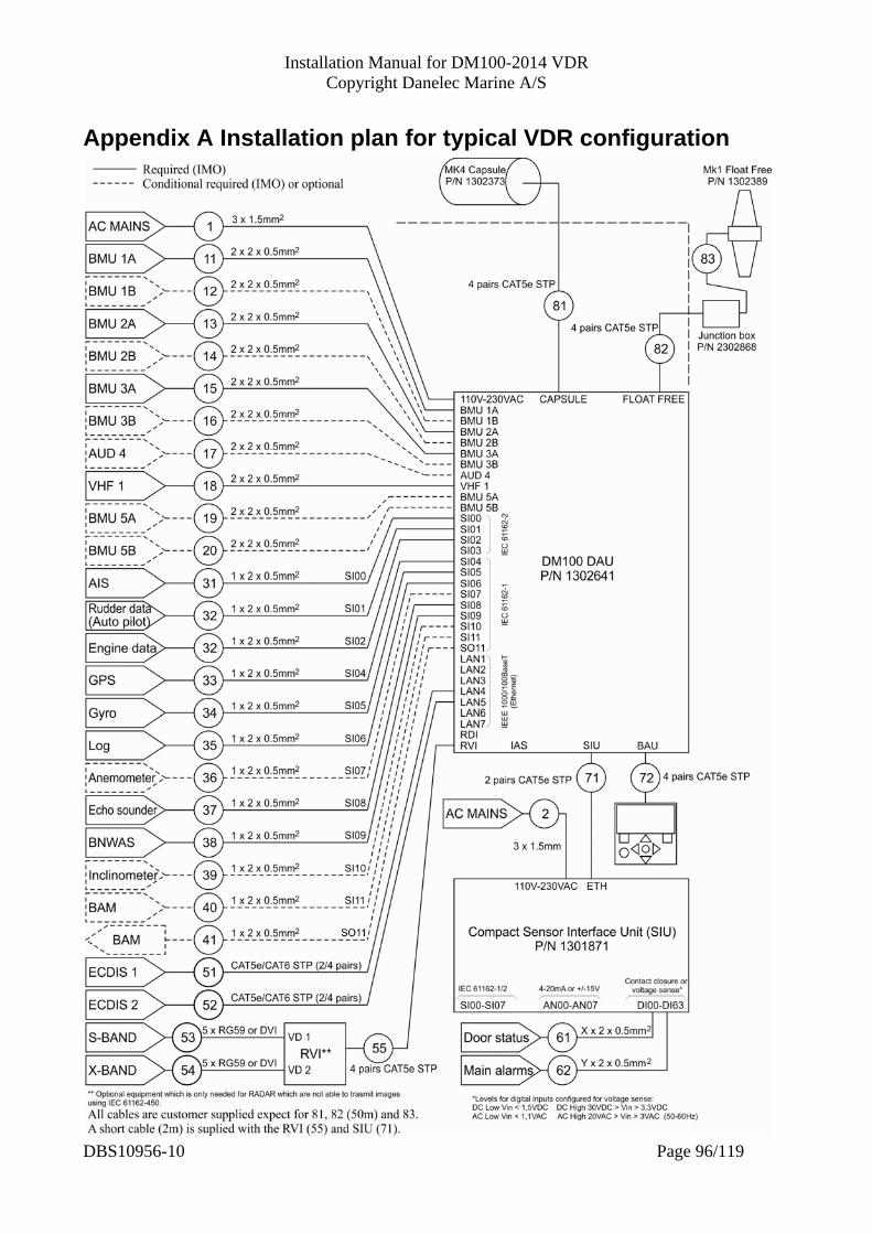
Installation Manual for DM100-2014 VDR Copyright Danelec Marine A/S
Appendix A Installation plan for typical VDR configuration
DBS10956-10 Page 96/119

Installation Manual for DM100-2014 VDR Copyright Danelec Marine A/S
Notes: Cable 1 Use only cable which is approved for AC mains Cable 11-17 and 19-20 Utilization of conductors for cable 11-17 and 19-20 when connected to a BMU Pair, conductor At BMU At DAU 1,1 V+ V+ 2,1 L+ L+ 2,2 L- L- 1,2 G G Cable 17 2 pairs are needed when AUD4 is used for a BMU; otherwise only one pair is needed. Cable 31-40 RX- corresponds to A terminal on the DPU RX+ corresponds to B terminal on the DPU Cable 41 Terminal A on the DPU corresponds to TX- Terminal B on the DPU corresponds to TX+ Cable 81, 82 CAT5e STP FRZH, 50m long. Supplied with the equipment. Cable 83 CAT6 STP cable, 1.5m long. The cable is permanently fixed to the Tron 40 float free capsule. It must be connected to the junction box.
DBS10956-10 Page 97/119
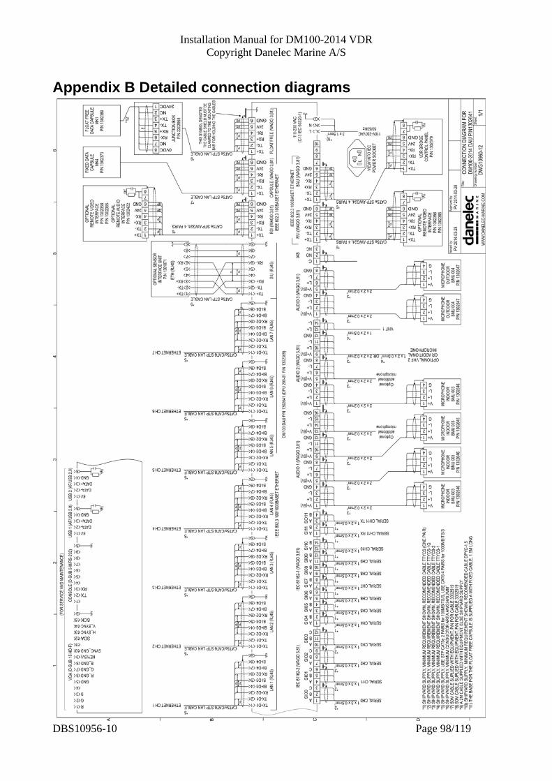
Installation Manual for DM100-2014 VDR Copyright Danelec Marine A/S
Appendix B Detailed connection diagrams
DBS10956-10 Page 98/119
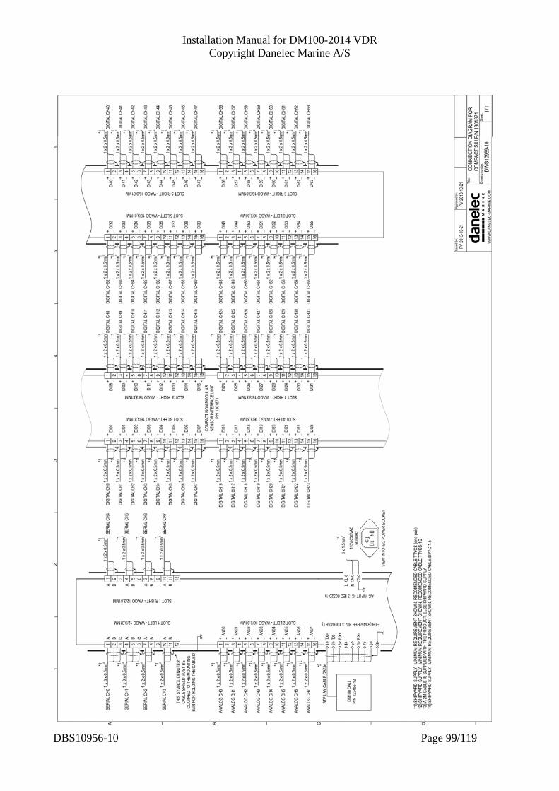
Installation Manual for DM100-2014 VDR Copyright Danelec Marine A/S
DBS10956-10 Page 99/119
Installation Manual for DM100-2014 VDR Copyright Danelec Marine A/S
Appendix C Installation of DAU - Use 8mm bolts or threaded studs and nuts. Washers with a 2 mm minimum thickness are required. - Leave 50mm of space on each side for ventilation. - The DAU must be protected from rain, seawater and direct sunlight See drawing on next page.
DBS10956-10 Page 100/119

Installation Manual for DM100-2014 VDR Copyright Danelec Marine A/S
DBS10956-10 Page 101/119
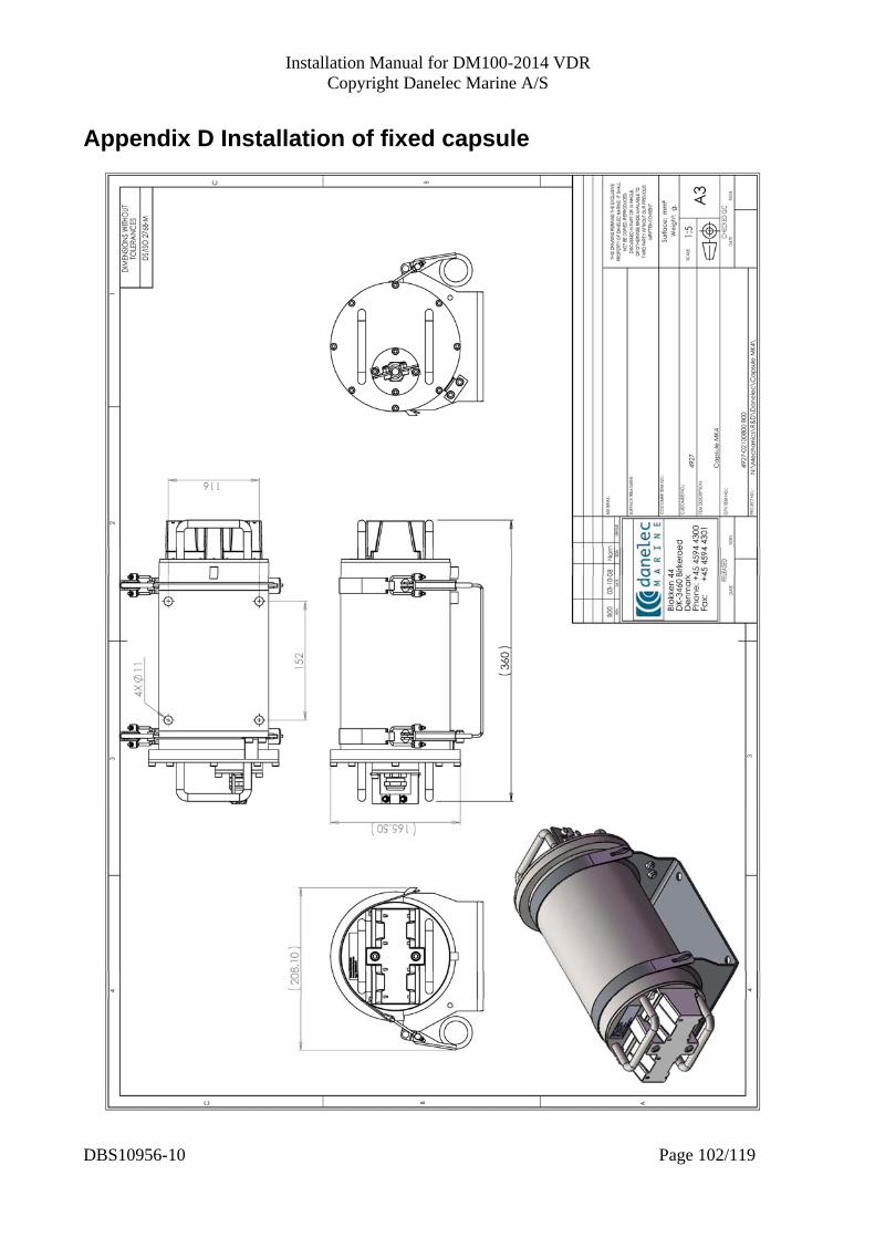
Installation Manual for DM100-2014 VDR Copyright Danelec Marine A/S
DBS10956-10 Page 102/119
Appendix D Installation of fixed capsule

Installation Manual for DM100-2014 VDR Copyright Danelec Marine A/S
Installation Manual for DM100-2014 VDR Copyright Danelec Marine A/S
DBS10956-10 Page 103/119
DBS10956-10 Page 103/119
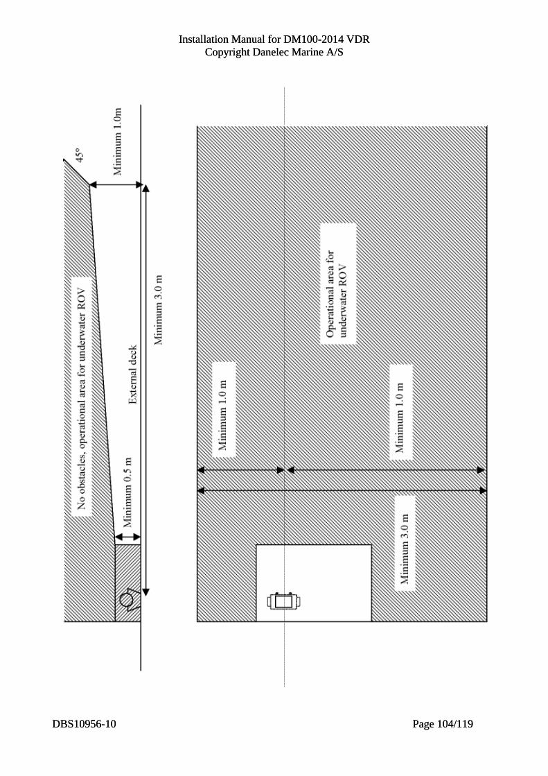
Installation Manual for DM100-2014 VDR Copyright Danelec Marine A/S
Installation Manual for DM100-2014 VDR Copyright Danelec Marine A/S
DBS10956-10 Page 104/119
DBS10956-10 Page 104/119
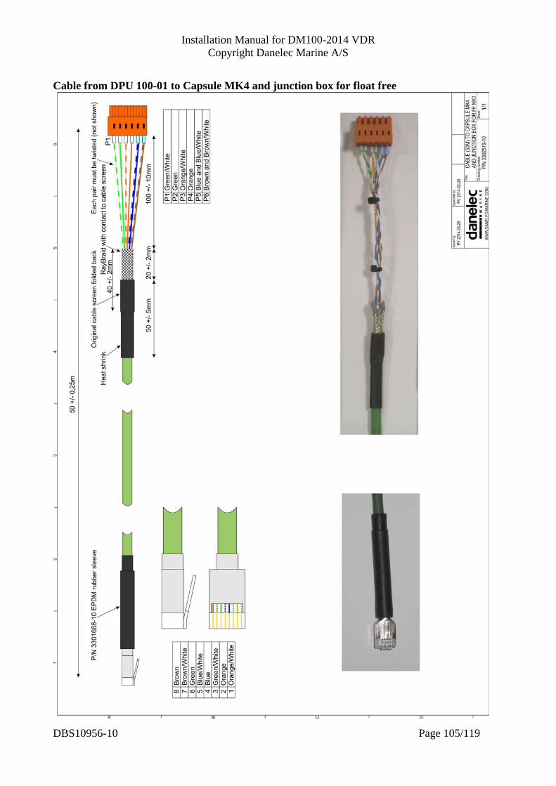
Installation Manual for DM100-2014 VDR Copyright Danelec Marine A/S
Cable from DPU 100-01 to Capsule MK4 and junction box for float free
DBS10956-10 Page 105/119
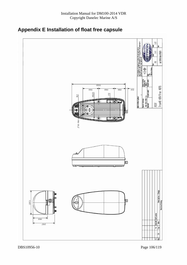
Installation Manual for DM100-2014 VDR Copyright Danelec Marine A/S
Appendix E Installation of float free capsule
DBS10956-10 Page 106/119
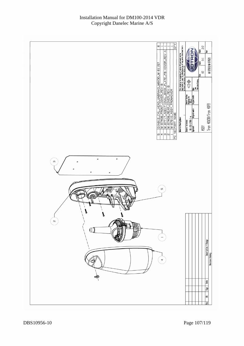
Installation Manual for DM100-2014 VDR Copyright Danelec Marine A/S
DBS10956-10 Page 107/119
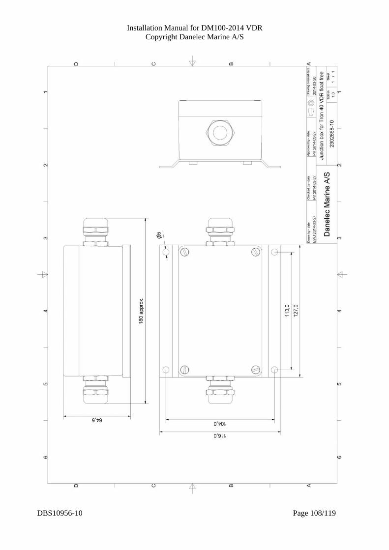
Installation Manual for DM100-2014 VDR Copyright Danelec Marine A/S
DBS10956-10 Page 108/119
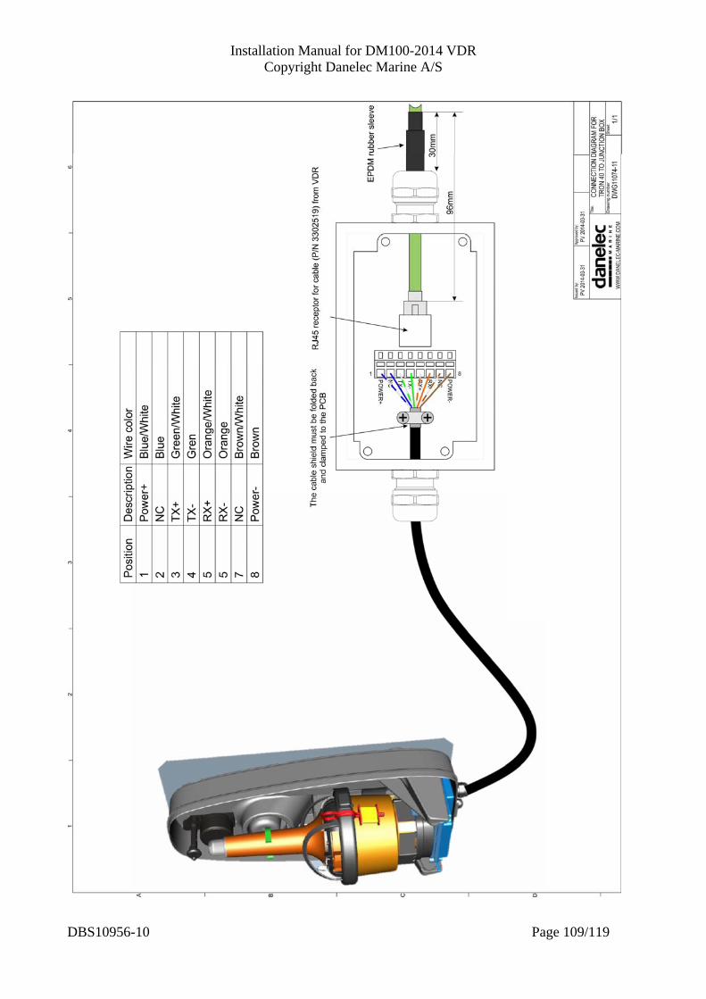
Installation Manual for DM100-2014 VDR Copyright Danelec Marine A/S
DBS10956-10 Page 109/119

Installation Manual for DM100-2014 VDR Copyright Danelec Marine A/S
Appendix F Installation of BMU
DBS10956-10 Page 110/119
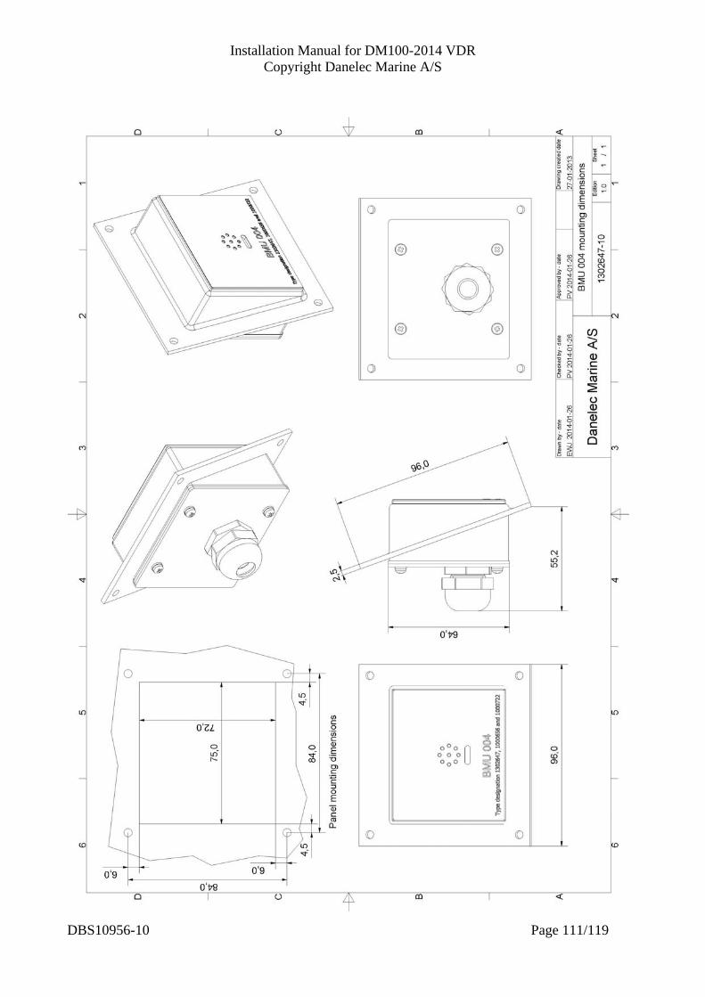
Installation Manual for DM100-2014 VDR Copyright Danelec Marine A/S
DBS10956-10 Page 111/119
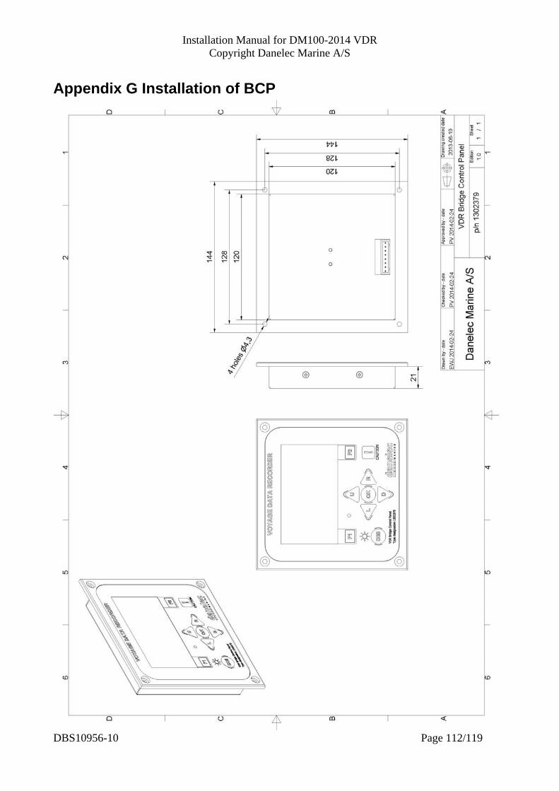
Installation Manual for DM100-2014 VDR Copyright Danelec Marine A/S
Appendix G Installation of BCP
DBS10956-10 Page 112/119
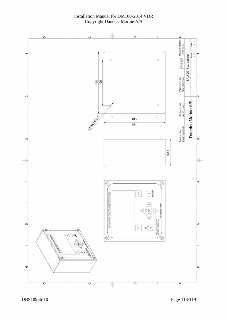
Installation Manual for DM100-2014 VDR Copyright Danelec Marine A/S
DBS10956-10 Page 113/119
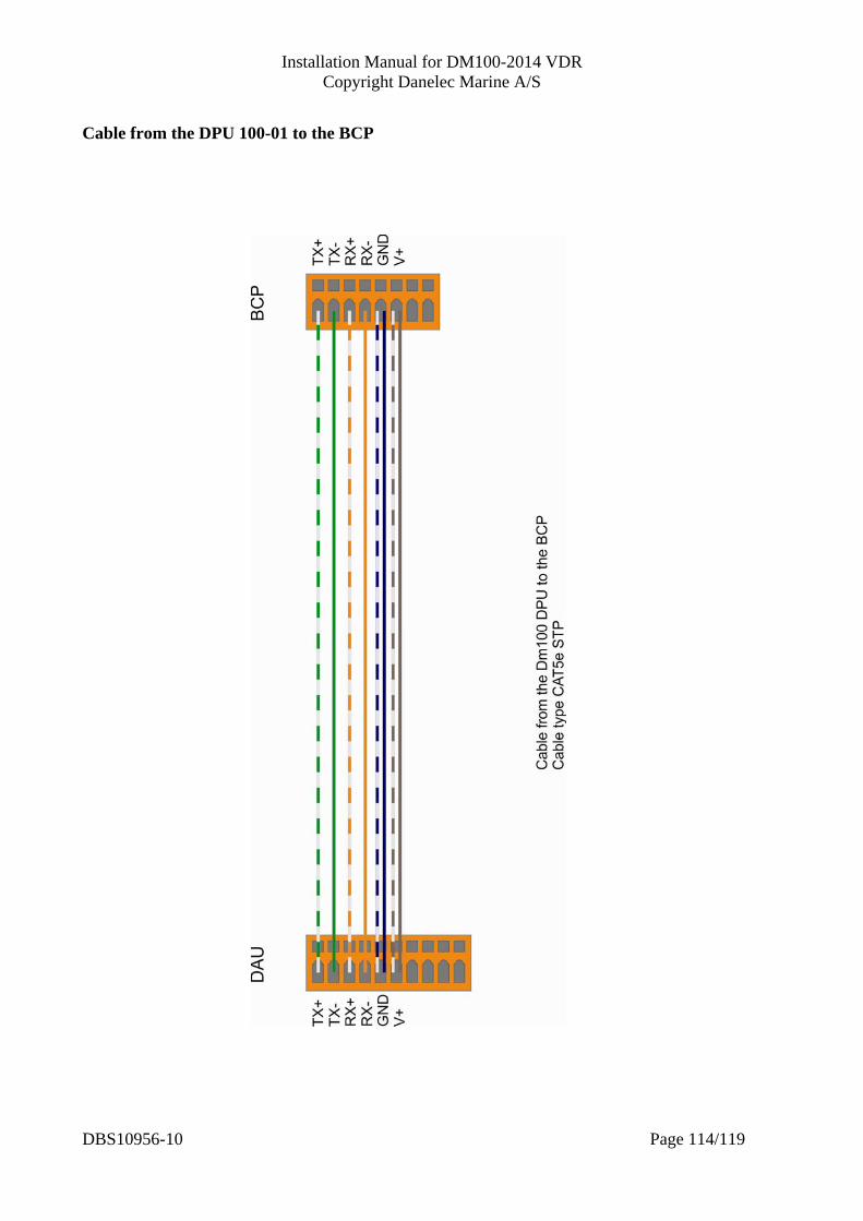
Installation Manual for DM100-2014 VDR Copyright Danelec Marine A/S
Cable from the DPU 100-01 to the BCP
DBS10956-10 Page 114/119

Installation Manual for DM100-2014 VDR Copyright Danelec Marine A/S
Appendix H Setup of configurator PC The default IP address of the VDR is 10.0.0.100 (255.0.0.0). A configurator PC, Replay PC or data extractor PC must use an IP address with the same range. Windows 7 Open the control panel for the “Network and Sharing Center”
’ Click on “Change adaptor settings”.
DBS10956-10 Page 115/119

Installation Manual for DM100-2014 VDR Copyright Danelec Marine A/S
Right click on the icon representing your Ethernet adaptor and select “Properties” from the drop down menu.
Open the “Properties” for “Internet Protocol 4”.
DBS10956-10 Page 116/119

Installation Manual for DM100-2014 VDR Copyright Danelec Marine A/S
Set the new IP address for the PC and click on “OK” (It is probably a good idea to write down the previous settings).
Click on “OK”
DBS10956-10 Page 117/119
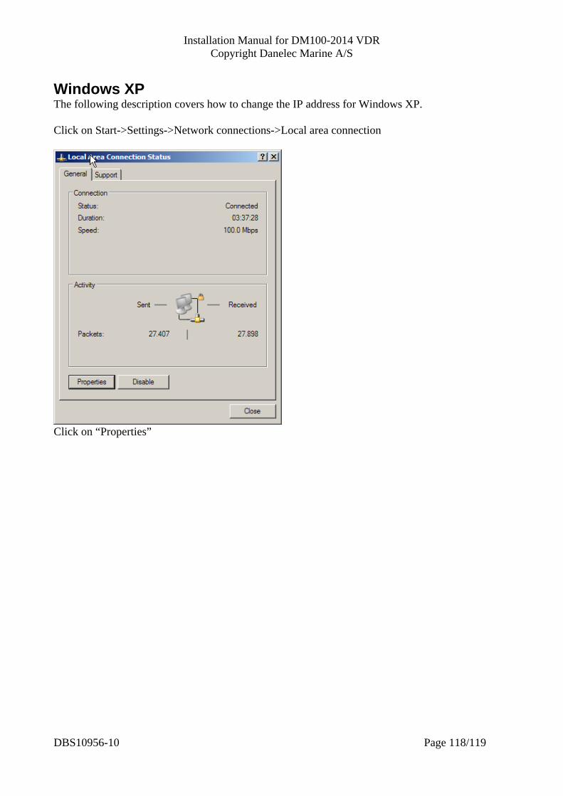
Installation Manual for DM100-2014 VDR Copyright Danelec Marine A/S
Windows XP The following description covers how to change the IP address for Windows XP. Click on Start->Settings->Network connections->Local area connection
Click on “Properties”
DBS10956-10 Page 118/119
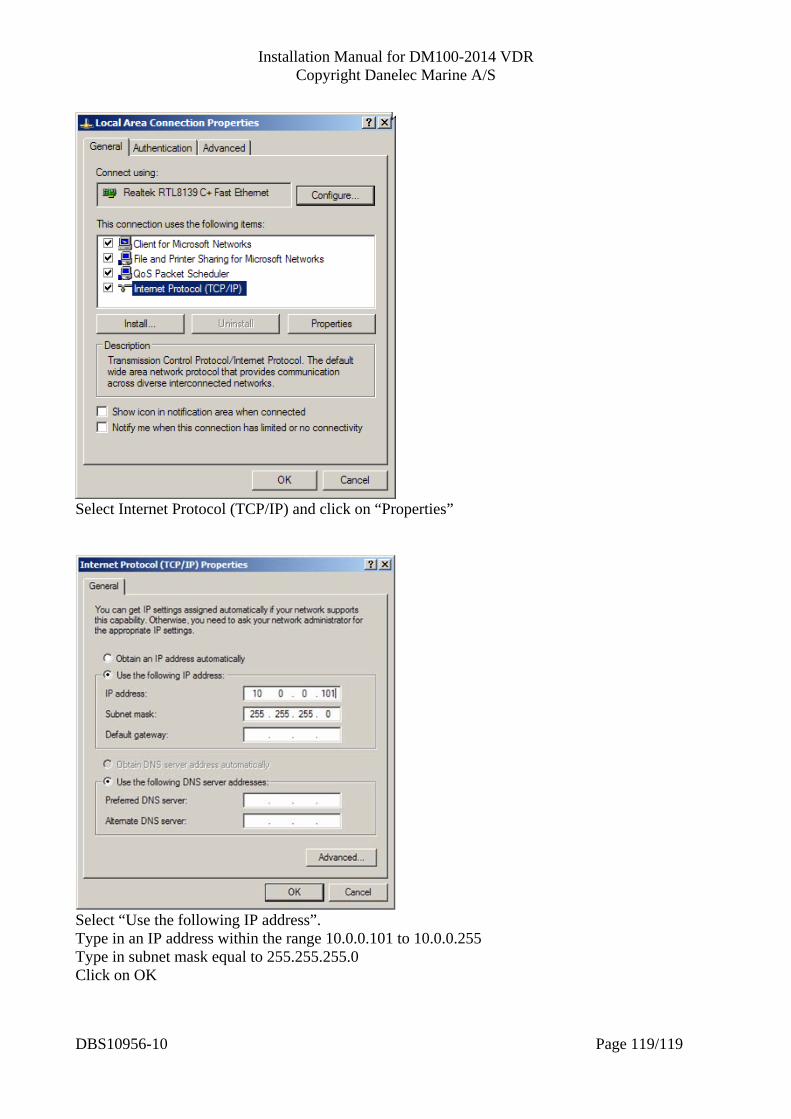
Installation Manual for DM100-2014 VDR Copyright Danelec Marine A/S
DBS10956-10 Page 119/119
Select Internet Protocol (TCP/IP) and click on “Properties”
Select “Use the following IP address”. Type in an IP address within the range 10.0.0.101 to 10.0.0.255 Type in subnet mask equal to 255.255.255.0 Click on OK


![VDR G4[e] S-VDR G4[e] - interschalt.com · Modular and scalable design ... VDR G4[e] S-VDR G4[e] Worldwide Network ... VDR Requirements S-VDR G4[e] S-VDR Requirements Overview](https://static.documents.pub/doc/80x56/5af3f3967f8b9a95468d4730/vdr-g4e-s-vdr-g4e-and-scalable-design-vdr-g4e-s-vdr-g4e-worldwide.jpg)


