All disclosures, notices and warranty conditions are being written on EKWB web page. Please check terms of use. Revision 1.1. Released on 13 th of March, 2012. This product is intended for installation only by expert users. Please consult with a qualified technician for installation. Improper installation may result in damage to your equipment. EK Water Blocks assumes no liability whatsoever, expressed or implied, for the use of these products, nor their installation. The following instructions are subject to change without notice. Please visit our web site at www.ekwaterblocks.com for updates. Before installation of this product please read important notice, disclosure and warranty conditions printed on the back of the box or our home page. STEP 1: QUICK OVERVIEW STEP 1.1: EK-TIM Indigo Xtreme: Engineered Thermal Interface for Socket 2011 (Intel Core™ i7 processors) Indigo Xtreme™ is an Engineered Thermal Interface (ETI) that fits neatly between a CPU lid and heat sink or waterblock to keep CPUs cooler. Unlike greases, metallic thermal interface pads or liquid metal alloys, Indigo Xtreme is a self-contained and sealed structure, deploying a Phase Change Metallic Alloy (PCMA) which reflows and fills surface defects on the CPU lid and heat sink. The resultant interfacial layer is void-free and robust, with low thermal contact and bulk resistance. Important: Unlike most thermal interface products, the Indigo Xtreme form-factor is optimized for each application. Attempting to use Indigo Xtreme with CPUs or heat sinks other than those specified may result in degraded performance or interfacial failure (See: Supported Hardware). STEP 1.2: Compatibility List: Supported Hardware: Supported CPUs: Socket 2011 • Core™ i7 Supported Waterblock/Heat Sink Types: In general, water blocks and heat sinks that contact entire surface of CPU lid are compatible with Indigo Xtreme. All EKWB CPU series water blocks water blocks are supported! Unsupported Heat Sink Types: Heat sinks that do not contact entire surface of CPU lid, or surfaces with channels between mounting base and heat pipes, are incompatible with Indigo Xtreme. Prior to the installation and reflow of Indigo Xtreme do not disable the Thermal Control feature that protects your CPU from overheating. STEP 2: INSTALLATION PROCEDURE STEP 1.3: ETI Kit Contents: The Indigo Xtreme ETI is offered as part of an Engineered Thermal Interface Kit. This kit includes several cleanroom-grade surface cleaning products for (2) complete installations. The ETI kit includes: Indigo Xtreme ETIs (2 installations) Cleanroom-grade dry wiper cloths Cotton cleaning swabs Indigo Xtreme Clean™ (sample size) Pair of powder-free nitrile gloves Detailed Installation Guide Check the condition of the ETI kit before installation; if any problem is found, contact Enerdyne Solutions for a replacement. Read entire instructions before beginning installation. Contact EKWB Support if you have any questions. STEP 2.1: Motherboard, CPU and Heat Sink/Block Removal: Remove the motherboard (from the PC case) and all heat sink clips and support mechanisms from the motherboard. Remove the CPU from the motherboard socket and place on a non-abrasive, lint-free surface for cleaning. Motherboard and clip support removal will facilitate proper alignment of the ETI to the CPU lid and heat sink. It is recommended that all heat sink mounting hardware be re-installed during Step 2.9. STEP 2.2: Thermal Interface (grease) Compound Removal: Using the supplied dry wiper cloth, apply pressure to thoroughly remove any existing interface grease from the CPU lid (including any grease residue within the lid vent located on the lower right corner of the lid) and heat sink. Clean with fresh areas of the wiper cloth until no visible grease residue is detected on the wiper. If removing metal pad or liquid metal TIM residue, refer to manufacturer’s specific cleaning methods. STEP 2.3: Put on Gloves: Prior to the final degreasing step, the supplied powder-free nitrile gloves must be worn to prevent any finger oils or contaminants from contacting the CPU lid, heat sink and ETI surfaces and to prevent skin contact with Indigo Xtreme Clean™. Stray grease compound can be mitigated as gloves are applied immediately following the Thermal Interface Compound Removal step. Installation manual for EK-TIM Indigo Extreme™
Transcript
All disclosures, notices and warranty conditions are being written on EKWB web page. Please check terms of use. Revision 1.1. Released on 13th of March, 2012.
This product is intended for installation only by expert users. Please consult with a qualified technician for installation. Improper installation may result in damage to your equipment. EK Water Blocks assumes no liability whatsoever, expressed or implied, for the use of these products, nor their installation. The following instructions are subject to change without notice. Please visit our web site at www.ekwaterblocks.com for updates. Before installation of this product please read important notice, disclosure and warranty conditions printed on the back of the box or our home page. STEP 1: QUICK OVERVIEW STEP 1.1: EK-TIM Indigo Xtreme: Engineered Thermal Interface for Socket 2011 (Intel Core™ i7 processors) Indigo Xtreme™ is an Engineered Thermal Interface (ETI) that fits neatly between a CPU lid and heat sink or waterblock to keep CPUs cooler. Unlike greases, metallic thermal interface pads or liquid metal alloys, Indigo Xtreme is a self-contained and sealed structure, deploying a Phase Change Metallic Alloy (PCMA) which reflows and fills surface defects on the CPU lid and heat sink. The resultant interfacial layer is void-free and robust, with low thermal contact and bulk resistance.
Important: Unlike most thermal interface products, the Indigo Xtreme form-factor is optimized for each application.
Attempting to use Indigo Xtreme with CPUs or heat sinks other than those specified may result in degraded performance or interfacial failure (See: Supported Hardware).
STEP 1.2: Compatibility List: Supported Hardware: Supported CPUs: Socket 2011 • Core™ i7 Supported Waterblock/Heat Sink Types: In general, water blocks and heat sinks that contact entire surface of CPU lid are compatible with Indigo Xtreme. All EKWB CPU series water blocks water blocks are supported! Unsupported Heat Sink Types: Heat sinks that do not contact entire surface of CPU lid, or surfaces with channels between mounting base and heat pipes, are incompatible with Indigo Xtreme. Prior to the installation and reflow of Indigo Xtreme do not disable the Thermal Control
feature that protects your CPU from overheating. STEP 2: INSTALLATION PROCEDURE STEP 1.3: ETI Kit Contents:
The Indigo Xtreme ETI is offered as part of an Engineered Thermal Interface Kit. This kit includes several cleanroom-grade surface cleaning products for (2) complete installations. The ETI kit includes: Indigo Xtreme ETIs (2 installations) Cleanroom-grade dry wiper cloths Cotton cleaning swabs Indigo Xtreme Clean™ (sample size) Pair of powder-free nitrile gloves Detailed Installation Guide Check the condition of the ETI kit before installation; if any problem is found,
contact Enerdyne Solutions for a replacement.
Read entire instructions before beginning installation. Contact EKWB Support if
you have any questions.
STEP 2.1: Motherboard, CPU and Heat Sink/Block Removal: Remove the motherboard (from the PC case) and all heat sink clips and support mechanisms from the motherboard. Remove the CPU from the motherboard socket and place on a non-abrasive, lint-free surface for cleaning. Motherboard and clip support removal will facilitate proper alignment of the ETI to the CPU
lid and heat sink. It is recommended that all heat sink mounting hardware be re-installed during Step 2.9. STEP 2.2: Thermal Interface (grease) Compound Removal:
Using the supplied dry wiper cloth, apply pressure to thoroughly remove any existing interface grease from the CPU lid (including any grease residue within the lid vent located on the lower right corner of the lid) and heat sink. Clean with fresh areas of the wiper cloth until no visible grease residue is detected on the wiper.
If removing metal pad or liquid metal TIM residue, refer to manufacturer’s specific cleaning methods.
STEP 2.3: Put on Gloves: Prior to the final degreasing step, the supplied powder-free nitrile gloves must be worn to prevent any finger oils or contaminants from contacting the CPU lid, heat sink and ETI surfaces and to prevent skin contact with Indigo Xtreme Clean™. Stray grease compound can be mitigated as gloves are applied immediately following the
Thermal Interface Compound Removal step.
Installation manual for EK-TIM Indigo Extreme™
All disclosures, notices and warranty conditions are being written on EKWB web page. Please check terms of use. Revision 1.1. Released on 13th of March, 2012.
STEP 2.5: CPU Installation: Install the CPU in the motherboard. Refer to motherboard or CPU installation instructions. The ETI can only be applied after correct installation of the CPU.
STEP 2.4: Degrease CPU lid and Heat Sink/Block Surfaces: Saturate a dry wiper cloth with Indigo Xtreme Clean™; use ~1/3 trial size bottle per ETI installation; thoroughly wipe the CPU lid; repeat with the heat sink interfacial surfaces. Continue to wipe each surface with fresh areas of the wiper until no visible residue is detected on the wiper. Wipe all surfaces of any visible lint, fibers, or particulates. Be prepared to wipe the CPU lid and heat sink surfaces immediately upon saturating
each dry wiper cloth as the Xtreme Clean™ solvent will quickly evaporate. When finished, seal the used wiper in the ETI kit clear bag. New CPUs or heat sinks must be degreased as well. Use only Indigo Xtreme Clean™ for the degreasing step.
Use the Xtreme Clean™ solvent in a well-ventilated area. Avoid contact with plastics (such as keyboards, computer cases, cooling fans, some waterblock housings, coolant tube fittings, cables, etc.). Also, avoid contact with elastomers (coolant tubing, gaskets, etc.).
STEP 2.6: Indigo Xtreme Handling: The Indigo Xtreme ETI may be handled on the blue surfaces only. ETI installation requires a lint-free environment.
Do not remove the clear Top and Bottom liners prior to the specific installation step. Do not bend, flex or puncture any portion of the ETI. Keep all chemical agents (Indigo Xtreme Clean™, etc.) away from the ETI.
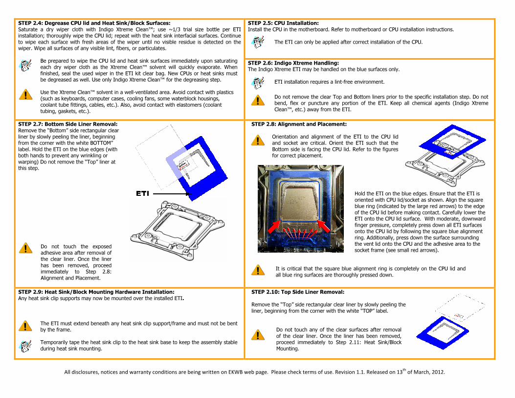
STEP 2.7: Bottom Side Liner Removal: Remove the “Bottom” side rectangular clear liner by slowly peeling the liner, beginning from the corner with the white BOTTOM” label. Hold the ETI on the blue edges (with both hands to prevent any wrinkling or warping) Do not remove the “Top” liner at this step.
Do not touch the exposed adhesive area after removal of the clear liner. Once the liner has been removed, proceed immediately to Step 2.8: Alignment and Placement.
STEP 2.8: Alignment and Placement: Orientation and alignment of the ETI to the CPU lid
and socket are critical. Orient the ETI such that the Bottom side is facing the CPU lid. Refer to the figures for correct placement.
Hold the ETI on the blue edges. Ensure that the ETI is oriented with CPU lid/socket as shown. Align the square blue ring (indicated by the large red arrows) to the edge of the CPU lid before making contact. Carefully lower the ETI onto the CPU lid surface. With moderate, downward finger pressure, completely press down all ETI surfaces onto the CPU lid by following the square blue alignment ring. Additionally, press down the surface surrounding the vent lid onto the CPU and the adhesive area to the socket frame (see small red arrows).
It is critical that the square blue alignment ring is completely on the CPU lid and
all blue ring surfaces are thoroughly pressed down.
STEP 2.9: Heat Sink/Block Mounting Hardware Installation: Any heat sink clip supports may now be mounted over the installed ETI.
The ETI must extend beneath any heat sink clip support/frame and must not be bent by the frame.
Temporarily tape the heat sink clip to the heat sink base to keep the assembly stable during heat sink mounting.
STEP 2.10: Top Side Liner Removal: Remove the “Top” side rectangular clear liner by slowly peeling the liner, beginning from the corner with the white “TOP” label.
Do not touch any of the clear surfaces after removal of the clear liner. Once the liner has been removed, proceed immediately to Step 2.11: Heat Sink/Block Mounting.
All disclosures, notices and warranty conditions are being written on EKWB web page. Please check terms of use. Revision 1.1. Released on 13th of March, 2012.
STEP 2.11: Heat Sink/Block Mounting: It is imperative that the heat sink or waterblock is aligned correctly before it makes
contact with the ETI. Avoid any twisting on the ETI as the heat sink is bolted/clamped down. Apply a uniform pressure to the sink (while clamping) to prevent it from shifting.
For Clip and Bolt mounted sinks/blocks: Initially tighten each bolt to latch onto
the clip support threading. Apply uniform torque to all of the bolts (by alternating the tightening of bolts) until fully tightened. For plastic Push-Pin mounted sinks/blocks: Start with the two push-pins opposite the socket hinge and apply enough force to lock the final two push-pins.
STEP 2.12: ETI Reflow: As part of installation, the Indigo Xtreme ETI must first be heated with the CPU running under load in order to reflow (melt) the PCMA.
The interface is highly thermally resistive without a complete reflow. Failure to perform the exact reflow procedure may result in unacceptable thermal performance.
A video demonstration of ETI reflow can be found at EKWB product page: http://www.ekwb.com
STEP 3: ETI REFLOW PROCEDURE:
1. Orient the computer such that the motherboard and CPU are in a horizontal position. 2. Plug in all fans and pump(s) and boot the computer. Clock frequency and voltage must be set back to default. 3. Open a CPU temperature monitoring program (such as SpeedFan™) and select the graphing option to track the profile of all core temperatures during reflow. Be certain the graph is open with all
core temperatures selected before proceeding to next the step. 4. Exercise the CPU with a “burn” program (such as Prime 95™) to generate adequate heat for reflow. Multi-core CPUs require one copy of the burn program for each core to be running
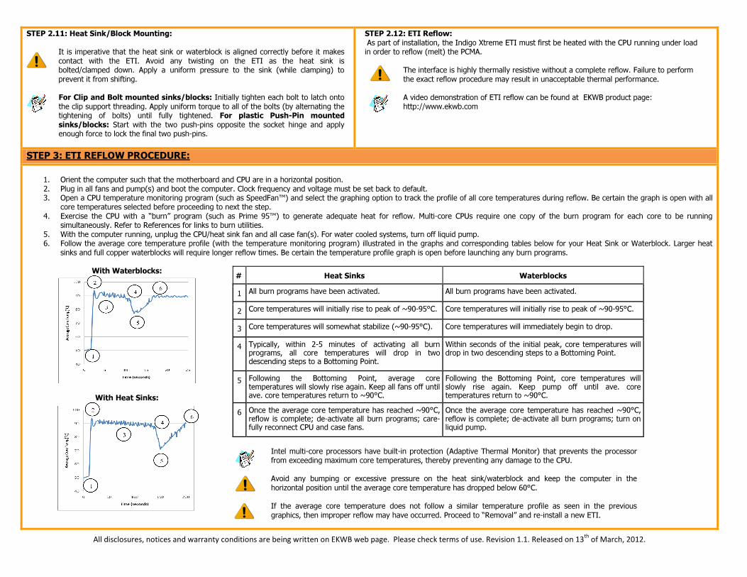
simultaneously. Refer to References for links to burn utilities. 5. With the computer running, unplug the CPU/heat sink fan and all case fan(s). For water cooled systems, turn off liquid pump. 6. Follow the average core temperature profile (with the temperature monitoring program) illustrated in the graphs and corresponding tables below for your Heat Sink or Waterblock. Larger heat
sinks and full copper waterblocks will require longer reflow times. Be certain the temperature profile graph is open before launching any burn programs.
With Waterblocks:
With Heat Sinks:
# Heat Sinks Waterblocks 1 All burn programs have been activated. All burn programs have been activated.
2 Core temperatures will initially rise to peak of ~90-95°C. Core temperatures will initially rise to peak of ~90-95°C.
3 Core temperatures will somewhat stabilize (~90-95°C). Core temperatures will immediately begin to drop.
4 Typically, within 2-5 minutes of activating all burn programs, all core temperatures will drop in two descending steps to a Bottoming Point.
Within seconds of the initial peak, core temperatures will drop in two descending steps to a Bottoming Point.
5 Following the Bottoming Point, average core temperatures will slowly rise again. Keep all fans off until ave. core temperatures return to ~90°C.
Following the Bottoming Point, core temperatures will slowly rise again. Keep pump off until ave. core temperatures return to ~90°C.
6 Once the average core temperature has reached ~90°C, reflow is complete; de-activate all burn programs; care-fully reconnect CPU and case fans.
Once the average core temperature has reached ~90°C, reflow is complete; de-activate all burn programs; turn on liquid pump.
Intel multi-core processors have built-in protection (Adaptive Thermal Monitor) that prevents the processor
from exceeding maximum core temperatures, thereby preventing any damage to the CPU.
Avoid any bumping or excessive pressure on the heat sink/waterblock and keep the computer in the horizontal position until the average core temperature has dropped below 60°C.
If the average core temperature does not follow a similar temperature profile as seen in the previous graphics, then improper reflow may have occurred. Proceed to “Removal” and re-install a new ETI.
All disclosures, notices and warranty conditions are being written on EKWB web page. Please check terms of use. Revision 1.1. Released on 13th of March, 2012.
STEP 4: REMOVAL OF EK-TIM INDIGO EXTREME: To disassemble, release the clamping force from the heat sink/waterblock. The ETI may then be removed (intact) by first slowly peeling each corner. The ETI is designed to adhesively capture excess alloy (from differences of CPU lid/heat sink interfacial roughness and planarity) on their surfaces. Any residual adhesive on the CPU or heat sink/waterblock may be removed with Xtreme Clean, acetone, or xylene and a clean wiper or cotton cleaning swab. Residual alloy is best removed by wetting the supplied swab with Xtreme Clean and gentling rotating the swab to loosen and collect the alloy particles. Indigo Xtreme is a single-use interface product and any removal of the heat sink (pre/post-reflow) will require a new ETI. All interface material and adhesive residue must be removed and the
CPU and heat sink re-cleaned (with the surface cleaning supplies including in the ETI kit only) prior to the re-installation of a new ETI. REFERENCES: Burn in program: IntelBurnTest: http://www.softpedia.com/get/System/Benchmarks/IntelBurnTest.shtml
Temperature monitors: Motherboard manufacturers usually supply a hardware monitor utility for their boards. CPUID.org's HWMonitor (Pro) or SpeedFan are the most popular temperature monitoring tool. It includes a real-time graphing mode that will aid in the processor burn-in: http://www.almico.com/speedfan.php ; http://www.cpuid.com/softwares/hwmonitor.html
The Material Safety Data Sheet (MSDS) for Indigo Xtreme Clean™ can be found at: http://www.ekwaterblocks.com/shop/EK-IM/MSDS_Indigo.pdf
Contact us for more information about this or other EK-TIM Indigo Xtreme applications at our website: http://www.ekwb.com
Store EK-TIM Indigo Xtreme at room temperature conditions of 22°C (72°F) and 50% R.H., preferably in the original sealed enclosure and plastic bag.
DISCLAIMER: EKWB d.o.o. and Enerdyne Solutions are not responsible for any damages due to external causes, including but not limited to, improper use, accident, neglect, alteration, repair, improper installation, improper testing, or damages caused by overclocking. Intel, Core i7 are trademarks of the Intel Corporation, USA. Indigo Xtreme is a trademark of: Enerdyne Solutions, Inc., 125 West North Bend Way, PO Box 2660, North Bend, WA., 98045 United States of America