Page 1
REV Revision Compiled Date
0 1st Edition S.Y. Shin 24/04/06
1 Page.7 Table, Page.10 Diagram Revision J.H. Ahn 26/10/07
2 Overall Context S.Y. Shin 31/10/07
3 Cable Spec. / Elec. & Mech. Spec. Revision S.Y. Shin 22/04/08
4 Product Type Change
(HiS-M184SF→HiS-M185SF)
S.Y. Shin
J.H. Ahn 13/11/08
5 Advanced Mechanical Test (5,400 Pa) S.Y. Shin 17/03/09
6 Earth Method, Clamping Position J.H. Ahn 18/12/09
7 SG-Series Included / Clamp Position Modification S.H. Woo 27/01/10
8 Specification Modification S.H. Woo 28/06/10
9 Attachment 1 Included J.H. Ahn 29/06/10
I n s ta l l a t ion
Manua l
Subject PV Module Installation Manual
Applicable Process PV System Installation Applicable
Products All PV Module Products
Solar Energy Dept.
Approved S.H. Song File No. Installation Manual (Rev.9).doc
Checked S.Y. Shin Doc. No. `DMP-C60A-001
Compiled J.H. Ahn Pages 18 Inc. Cover
Page 2
PV Module Installation Manual (Rev.6)
)
Solar Energy Dept. 2/18
1. General Information This installation manual provides information for Hyundai Crystalline-Silicon Photovoltaic Modules.
Serial Number Structure: YYMMDD-XX-MXXXSF(SG)-0001(~9999)
(Ex. 090819-11-M221SG-0005)
◈ YYMMDD: Production Date
◈ XX: Production Line
◈ MXXXSF: Type of Module
◈ 0001~9999: Production Number
1.1 Disclaimer of Liability Hyundai Heavy Industries (HHI) shall be indemnified for loss, damage and cost increase related to
the use of this manual.
The information included in this manual is considered to be reliable, but is not considered as lawful
of direct/indirect express or guarantee.
Without prior notice, HHI holds rights to change the products, the specification and the manual.
1.2 Installation of a PV module requires a high level of installation expertise. Therefore an installation
engineer must fully understand this manual before installation, wiring, operation and handling.
Installation and wiring must be executed by an authorized electrical engineer or by someone under
supervision of such an engineer.
1.3 ◈ Electric parts such as connectors may cause burns, discharge or shock regardless of whether
or not they are connected.
◈ The back sheet of the PV module must be kept from any damage or scratching to prevent
electric shock and fire.
◈ Unauthorized personnel are not permitted to open the cover of a junction box to prevent electric
shock.
◈ Do not stand or walk on a PV module.
◈ Do not disassemble or remove any part of a PV module to prevent electric shock, fire or
damage.
Page 3
PV Module Installation Manual (Rev.6)
)
Solar Energy Dept. 3/18
◈ For other parts of a PV system such as inverters, batteries and charge controllers, please follow
the safety instruction of the manufacturers.
1.4 ◈ An installation engineer must be careful of any risk of electric shock or injury during installation.
◈ Under sunlight or any other light source, a PV module generates DC electricity. Even though the
voltage and the current of the PV module is low, the risk of electric shock and burn still exists.
◈ During installation, the front side of PV modules must be covered to avoid electricity generation.
◈ The risk of electric shock increases with higher voltage in series connection and with higher
current in parallel connection.
◈ All PV modules and installation instruments must be dry when being installed.
◈ Children and unauthorized persons must keep distance from PV modules.
◈ All PV modules must be earthed.
◈ Safety equipment is necessary to protect any contact to 30 Vdc or above.
◈ A PV module should be carried by two persons with slip-proof gloves.
◈ Please don’t pick up PV modules using cables or the junction box.
◈ Please don’t drop anything on PV modules.
◈ Please check the safety of all other parts of the PV system to prevent any electric shock and fire.
◈ Please do not install where inflammable gas or vapor exist because sparks may occur.
◈ Please do not leave un-fixed or unsafe PV modules unattended.
◈ Please do not drop a PV module.
◈ Please do not use any damaged PV module to prevent any fire, electric shock or injury.
◈ Please do not focus light on a PV module to prevent any fire and damage.
◈ Please do not touch the terminals of a junction box to prevent any electric shock or injury.
◈ Please do not re-arrange the bypass diodes to prevent any electric shock or injury.
1.5 ◈ Only for proper use.
◈ Please do not use paint or adhesive to prevent any performance drop, damage, or incapability
of back sheet or front glass.
Page 4
PV Module Installation Manual (Rev.6)
)
Solar Energy Dept. 4/18
2. General Safety Please follow all requirements of authorization, installation and inspection.
◈ Please contact an authorized person to find out all authorization, installation, and inspection
requirements.
◈ All PV systems must be earthed. If there is no special regulation, please follow the National
Electrical Code (US), the Canadian Electric Code (Canada) or other national codes.
◈ Please check the strength of buildings or support structures where PV modules are designed
to be installed. Some additional structures may be necessary for safe installation. All installation
must conform with all fire safety regulations. Additional parts to check earth failure, fuse and
isolation may be necessary.
◈ Do not use different PV modules in the same PV system.
◈ Please follow all safety regulations of other parts of the PV system.
UL Listing Information The below must be considered carefully for installation to meet UL requirements.
1) Please use single or non-hollowed copper wire. For module connection and ambient use,
please use radiation-proof cables.
2) Please read carefully all technical requirements about installation and specifications in this
paragraph.
3) The module frame must be earthed. If an earth wire over 6 mm2 (10 AWG) is required, an
installer must provide proper terminal connectors.
3. Installation 3.1 General
◈ Before installation and operation, this manual must be well understood. This paragraph includes
necessary information of electrical and mechanical specifications.
◈ During installation, PV modules must be fixed considering any possible wind load and snow
load.
◈ Do not drill on the module frame for an additional hole. Doing so will render the warranty invalid.
◈ Installation materials must be resistant against any corrosion to protect the module frame and
installation structures.
◈ During installation, please avoid any possible shade by buildings or trees. In particular, please
consider any partial shade during daylight hours.
◈ For more information about standard installation, please inquire to authorized personnel of HHI.
Page 5
PV Module Installation Manual (Rev.6)
)
Solar Energy Dept. 5/18
3.2 Notes on Installation ◈ A gap between a PV module frame and an installed object is necessary for cooled air circulation.
Do not seal this gap.
◈ The recommended Standoff height is a minimum of 10.16 cm (4 inch) to conform with UL First
Class C.
3.3 General Operation Condition HHI recommends PV modules should be operated under General Operation Conditions (GOC). Do
not install at a site without GOC approval or under the special conditions outlined below.
1. General Operation Conditions
(1) Ground purpose only.
(2) Ambient Temperature: -20℃ (-4℉) ~ 40℃ (104℉)
(3) Relative Humidity: 45% ~ 95%
(4) Installation Site: Max. 1,000 m (3,280 ft) above sea level. If wind load is not greater than
5,400 N/㎡, installation over 1,000 m (3,280 ft) above sea level is permitted.
2. Special Conditions
(1) Please consider that actual operation conditions may differ with the general operation
conditions.
(2) Chloride is an important factor to be considered carefully during installation.
(3) Hail, snow, sand, and dirt are important factors to be considered carefully during
installation.
(4) Air pollution, chemical gases, acid rain, and smoke are important factors to be considered
carefully during installation.
(5) Modules must not be installed nor operated in areas where salinity damage is above
normal or excessive.
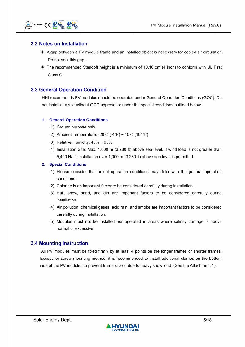
3.4 Mounting Instruction All PV modules must be fixed firmly by at least 4 points on the longer frames or shorter frames.
Except for screw mounting method, it is recommended to install additional clamps on the bottom
side of the PV modules to prevent frame slip-off due to heavy snow load. (See the Attachment 1).
Page 6
PV Module Installation Manual (Rev.6)
)
Solar Energy Dept. 6/18
※ Notice
Mounting Holes Locations: 220 mm and 370 mm from the end of longer frames
See the Attachment 1 for more information about mechanical strength
Picture 1. SF-Series Installation Position
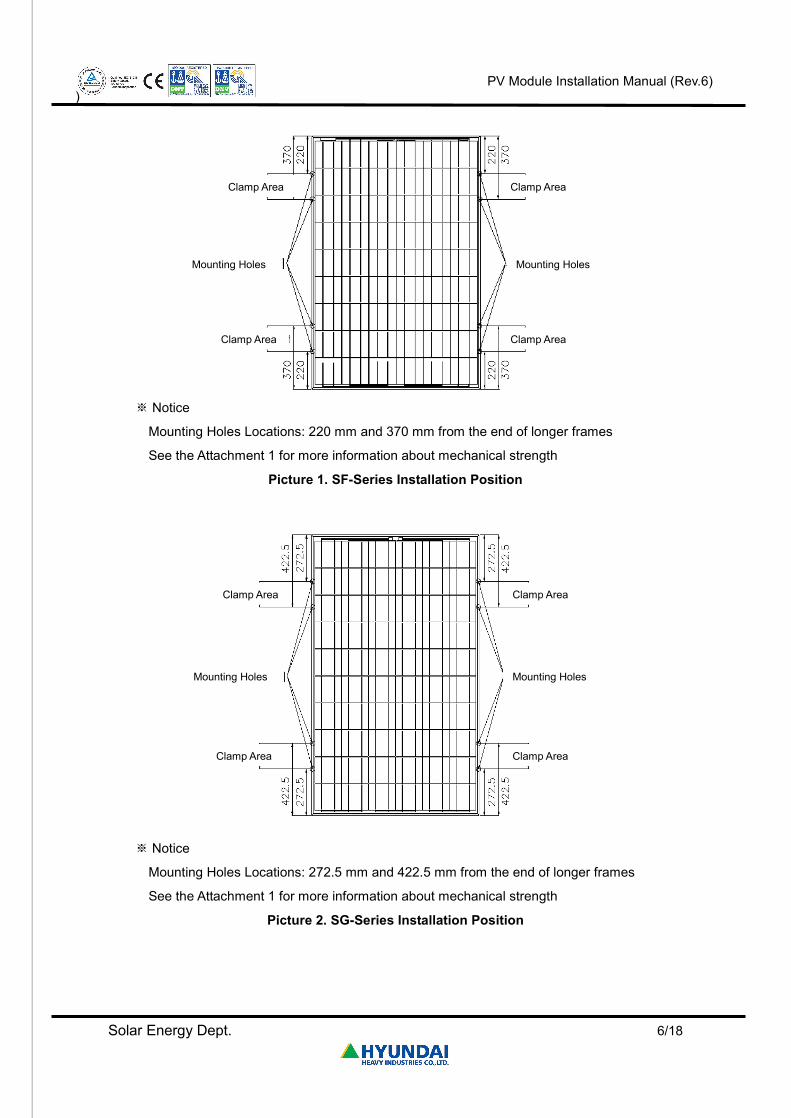
※ Notice
Mounting Holes Locations: 272.5 mm and 422.5 mm from the end of longer frames
See the Attachment 1 for more information about mechanical strength
Picture 2. SG-Series Installation Position
Clamp Area Clamp Area
Clamp Area Clamp Area
Mounting Holes Mounting Holes
Clamp Area Clamp Area
Clamp Area Clamp Area
Mounting Holes Mounting Holes
Page 7
PV Module Installation Manual (Rev.6)
)
Solar Energy Dept. 7/18
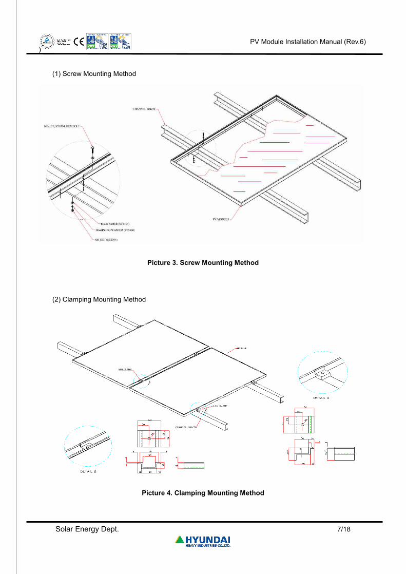
(1) Screw Mounting Method
Picture 3. Screw Mounting Method
(2) Clamping Mounting Method
Picture 4. Clamping Mounting Method
Page 8
PV Module Installation Manual (Rev.6)
)
Solar Energy Dept. 8/18
4. Specifications 4.1 Notes on Specifications
◈ Nominal Electrical Characteristics : Within 3% under Standard Test Conditions (STC),
Standard Test Conditions (STC): Irradiation 1,000 W/㎡, Cell Temperature 25 ℃, 1.5 AM
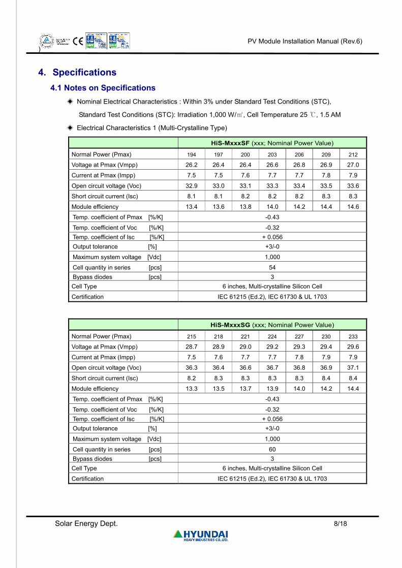
◈ Electrical Characteristics 1 (Multi-Crystalline Type)
HiS-MxxxSF (xxx; Nominal Power Value)
Normal Power (Pmax) 194 197 200 203 206 209 212
Voltage at Pmax (Vmpp) 26.2 26.4 26.4 26.6 26.8 26.9 27.0
Current at Pmax (Impp) 7.5 7.5 7.6 7.7 7.7 7.8 7.9
Open circuit voltage (Voc) 32.9 33.0 33.1 33.3 33.4 33.5 33.6
Short circuit current (Isc) 8.1 8.1 8.2 8.2 8.2 8.3 8.3
Module efficiency 13.4 13.6 13.8 14.0 14.2 14.4 14.6
Temp. coefficient of Pmax [%/K] -0.43
Temp. coefficient of Voc [%/K] -0.32 Temp. coefficient of Isc [%/K] + 0.056 Output tolerance [%] +3/-0
Maximum system voltage [Vdc] 1,000
Cell quantity in series [pcs] 54 Bypass diodes [pcs] 3 Cell Type 6 inches, Multi-crystalline Silicon Cell
Certification IEC 61215 (Ed.2), IEC 61730 & UL 1703
HiS-MxxxSG (xxx; Nominal Power Value)
Normal Power (Pmax) 215 218 221 224 227 230 233
Voltage at Pmax (Vmpp) 28.7 28.9 29.0 29.2 29.3 29.4 29.6
Current at Pmax (Impp) 7.5 7.6 7.7 7.7 7.8 7.9 7.9
Open circuit voltage (Voc) 36.3 36.4 36.6 36.7 36.8 36.9 37.1
Short circuit current (Isc) 8.2 8.3 8.3 8.3 8.3 8.4 8.4
Module efficiency 13.3 13.5 13.7 13.9 14.0 14.2 14.4
Temp. coefficient of Pmax [%/K] -0.43
Temp. coefficient of Voc [%/K] -0.32 Temp. coefficient of Isc [%/K] + 0.056 Output tolerance [%] +3/-0
Maximum system voltage [Vdc] 1,000
Cell quantity in series [pcs] 60 Bypass diodes [pcs] 3 Cell Type 6 inches, Multi-crystalline Silicon Cell
Certification IEC 61215 (Ed.2), IEC 61730 & UL 1703
Page 9
PV Module Installation Manual (Rev.6)
)
Solar Energy Dept. 9/18
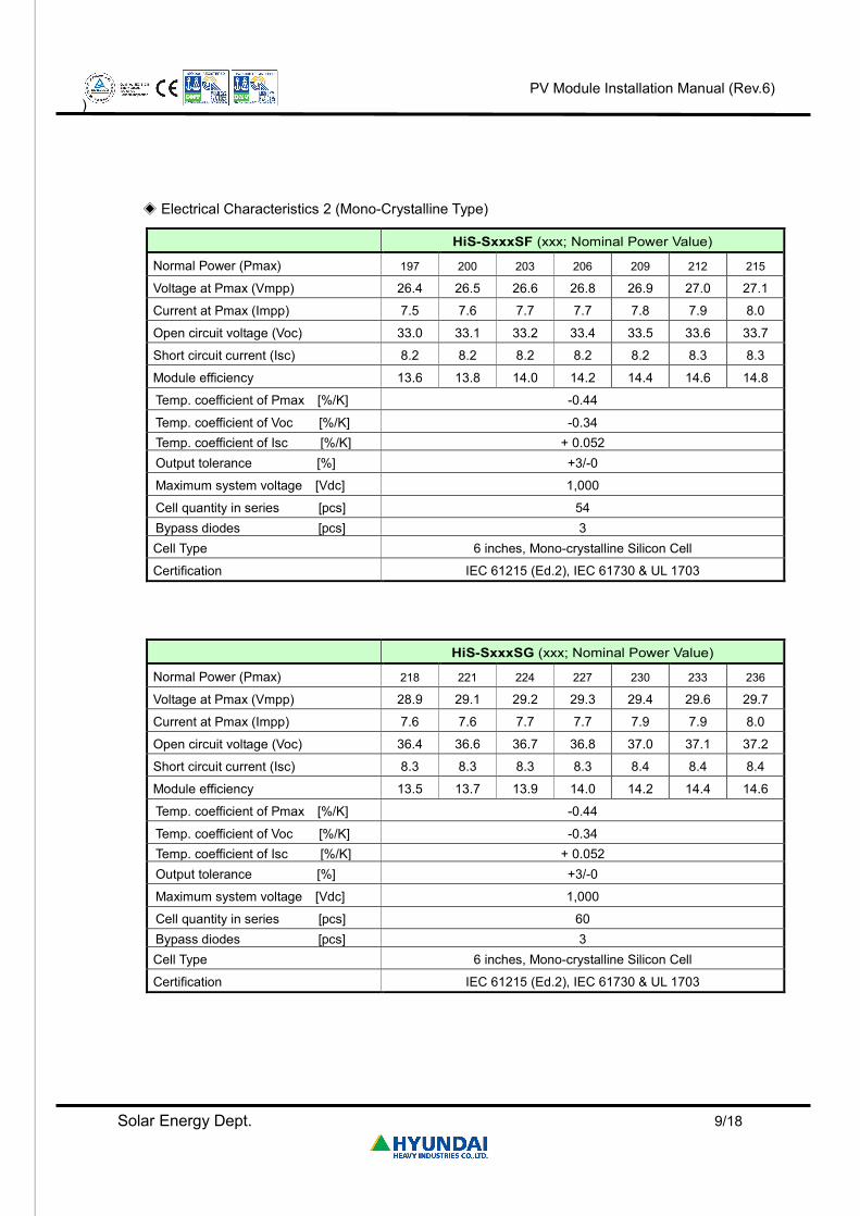
◈ Electrical Characteristics 2 (Mono-Crystalline Type)
HiS-SxxxSF (xxx; Nominal Power Value)
Normal Power (Pmax) 197 200 203 206 209 212 215
Voltage at Pmax (Vmpp) 26.4 26.5 26.6 26.8 26.9 27.0 27.1
Current at Pmax (Impp) 7.5 7.6 7.7 7.7 7.8 7.9 8.0
Open circuit voltage (Voc) 33.0 33.1 33.2 33.4 33.5 33.6 33.7
Short circuit current (Isc) 8.2 8.2 8.2 8.2 8.2 8.3 8.3
Module efficiency 13.6 13.8 14.0 14.2 14.4 14.6 14.8
Temp. coefficient of Pmax [%/K] -0.44
Temp. coefficient of Voc [%/K] -0.34 Temp. coefficient of Isc [%/K] + 0.052 Output tolerance [%] +3/-0
Maximum system voltage [Vdc] 1,000
Cell quantity in series [pcs] 54 Bypass diodes [pcs] 3 Cell Type 6 inches, Mono-crystalline Silicon Cell
Certification IEC 61215 (Ed.2), IEC 61730 & UL 1703
HiS-SxxxSG (xxx; Nominal Power Value)
Normal Power (Pmax) 218 221 224 227 230 233 236
Voltage at Pmax (Vmpp) 28.9 29.1 29.2 29.3 29.4 29.6 29.7
Current at Pmax (Impp) 7.6 7.6 7.7 7.7 7.9 7.9 8.0
Open circuit voltage (Voc) 36.4 36.6 36.7 36.8 37.0 37.1 37.2
Short circuit current (Isc) 8.3 8.3 8.3 8.3 8.4 8.4 8.4
Module efficiency 13.5 13.7 13.9 14.0 14.2 14.4 14.6
Temp. coefficient of Pmax [%/K] -0.44
Temp. coefficient of Voc [%/K] -0.34 Temp. coefficient of Isc [%/K] + 0.052 Output tolerance [%] +3/-0
Maximum system voltage [Vdc] 1,000
Cell quantity in series [pcs] 60 Bypass diodes [pcs] 3 Cell Type 6 inches, Mono-crystalline Silicon Cell
Certification IEC 61215 (Ed.2), IEC 61730 & UL 1703
Page 10
PV Module Installation Manual (Rev.6)
)
Solar Energy Dept. 10/18
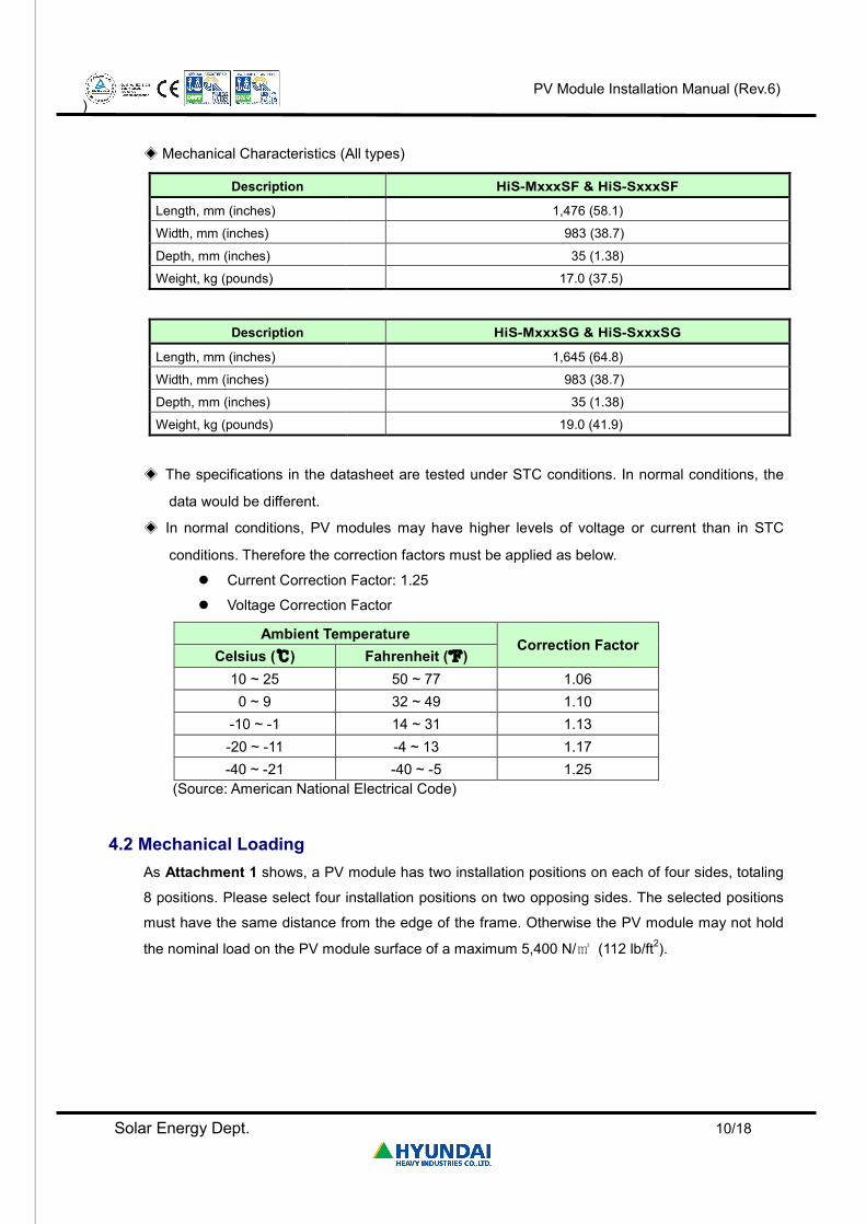
◈ Mechanical Characteristics (All types)
Description HiS-MxxxSF & HiS-SxxxSF
Length, mm (inches) 1,476 (58.1)
Width, mm (inches) 983 (38.7)
Depth, mm (inches) 35 (1.38)
Weight, kg (pounds) 17.0 (37.5)
Description HiS-MxxxSG & HiS-SxxxSG
Length, mm (inches) 1,645 (64.8)
Width, mm (inches) 983 (38.7)
Depth, mm (inches) 35 (1.38)
Weight, kg (pounds) 19.0 (41.9)
◈ The specifications in the datasheet are tested under STC conditions. In normal conditions, the
data would be different.
◈ In normal conditions, PV modules may have higher levels of voltage or current than in STC
conditions. Therefore the correction factors must be applied as below.
l Current Correction Factor: 1.25
l Voltage Correction Factor
Ambient Temperature Correction Factor
Celsius (℃) Fahrenheit (℉) 10 ~ 25 50 ~ 77 1.06
0 ~ 9 32 ~ 49 1.10 -10 ~ -1 14 ~ 31 1.13 -20 ~ -11 -4 ~ 13 1.17 -40 ~ -21 -40 ~ -5 1.25
(Source: American National Electrical Code)
4.2 Mechanical Loading As Attachment 1 shows, a PV module has two installation positions on each of four sides, totaling
8 positions. Please select four installation positions on two opposing sides. The selected positions
must have the same distance from the edge of the frame. Otherwise the PV module may not hold
the nominal load on the PV module surface of a maximum 5,400 N/㎡ (112 lb/ft2).
Page 11
PV Module Installation Manual (Rev.6)
)
Solar Energy Dept. 11/18
5. Wiring 5.1 General
All wiring must adhere to the proper electrical codes. The wiring must adhere to the NEC (US) or
the CEC (Canada).
◈ Wiring work must be done by a certified and authorized engineer.
◈ Wiring must secure the safety of the human body and prevent self-damage.
◈ PV modules for one serial connection must have identical electrical characteristics (Vmpp, Impp,
Voc, Isc).
◈ Do not connect PV modules directly parallel to one another without the junction box.
5.2 Module Wiring ◈ The maximum number of modules in a series connection is 24.
◈ The maximum system voltage must not be more than 1,000 V.
◈ PV modules are not designed to be connected to loads directly. Therefore, a proper inverter
must be connected.
◈ Bypass diodes are equipped on the modules from the factory. Incorrect connection may cause
damage to the bypass diodes, cable and junction box.
5.3 Array Wiring ‘Array’ is defined as a module arrangement with combined electrical connection. The array must be
insulated to resist against the possible maximum open-circuit voltage. Also, solar radiation-proof
copper wires must be used for array wiring. Installation must be considered in connection with local
electrical specifications.
5.4 Earth Ground Wiring To prevent electric shock and fire, an earth must be done on the frames of PV modules and array.
The array frame must be earthed according to NEC Article 250 (US) or CEC (Canada). There is an
earth hole in the center of the module frame. Using this hole, an earth conductor and the module
frame must be connected and earthed. (See the Picture 7.)
Page 12
PV Module Installation Manual (Rev.6)
)
Solar Energy Dept. 12/18
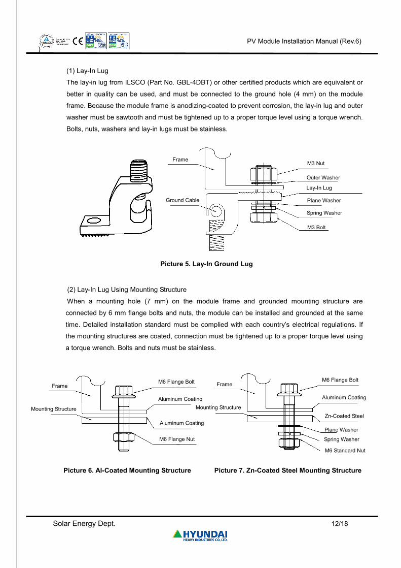
(1) Lay-In Lug
The lay-in lug from ILSCO (Part No. GBL-4DBT) or other certified products which are equivalent or
better in quality can be used, and must be connected to the ground hole (4 mm) on the module
frame. Because the module frame is anodizing-coated to prevent corrosion, the lay-in lug and outer
washer must be sawtooth and must be tightened up to a proper torque level using a torque wrench.
Bolts, nuts, washers and lay-in lugs must be stainless.
Picture 5. Lay-In Ground Lug
(2) Lay-In Lug Using Mounting Structure
When a mounting hole (7 mm) on the module frame and grounded mounting structure are
connected by 6 mm flange bolts and nuts, the module can be installed and grounded at the same
time. Detailed installation standard must be complied with each country’s electrical regulations. If
the mounting structures are coated, connection must be tightened up to a proper torque level using
a torque wrench. Bolts and nuts must be stainless.
Picture 6. Al-Coated Mounting Structure Picture 7. Zn-Coated Steel Mounting Structure
Frame
Ground Cable
M3 Nut
Outer Washer
Lay-In Lug
Plane Washer
Spring Washer
M3 Bolt
Frame
Mounting Structure
M6 Flange Bolt
Aluminum Coating
Aluminum Coating
M6 Flange Nut
Frame
Mounting Structure
M6 Flange Bolt
Aluminum Coating
Zn-Coated Steel
Plane Washer
Spring Washer
M6 Standard Nut
Page 13
PV Module Installation Manual (Rev.6)
)
Solar Energy Dept. 13/18
5.5 Module Terminations
A junction box is equipped on each PV module for system array. Also, quick connectors are
equipped for module connection. For more information about electrical connection, please inquire
to an authorized engineer of HHI.
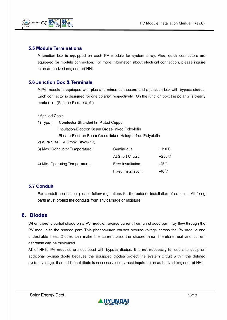
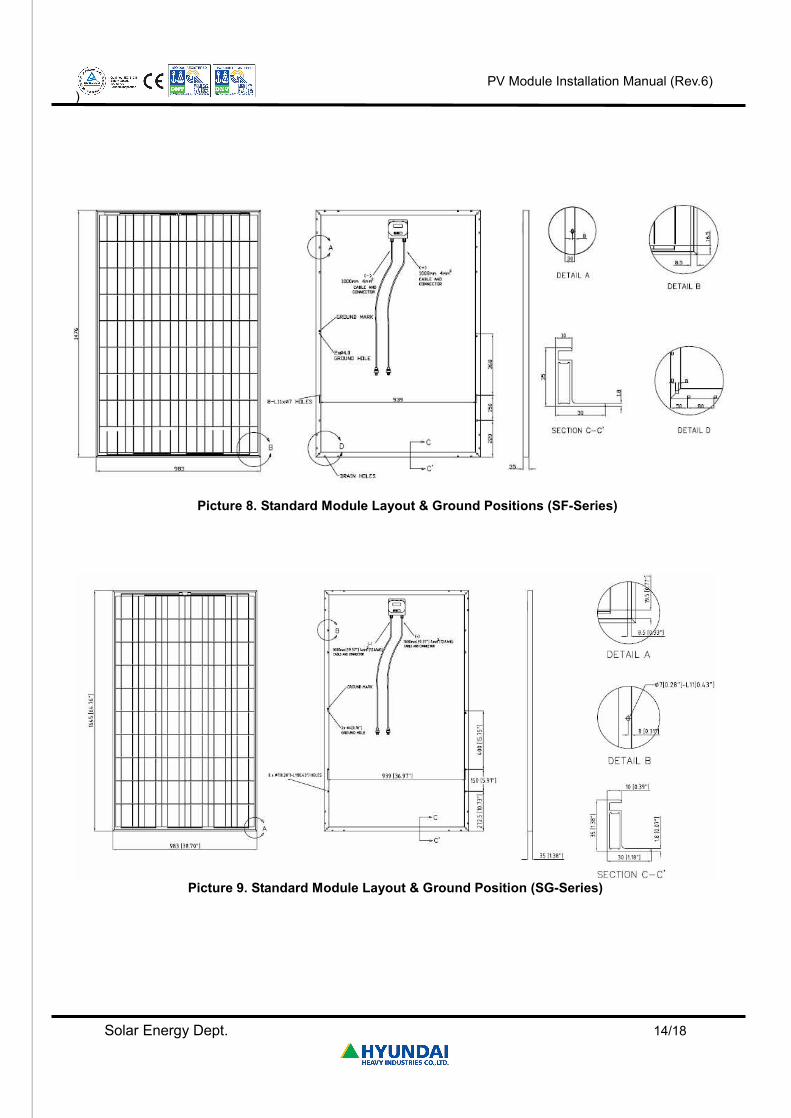
5.6 Junction Box & Terminals A PV module is equipped with plus and minus connectors and a junction box with bypass diodes.
Each connector is designed for one polarity, respectively. (On the junction box, the polarity is clearly
marked.) (See the Picture 8, 9.)
* Applied Cable
1) Type; Conductor-Stranded tin Plated Copper
Insulation-Electron Beam Cross-linked Polyolefin
Sheath-Electron Beam Cross-linked Halogen-free Polyolefin
2) Wire Size; 4.0 mm2 (AWG 12)
3) Max. Conductor Temperature; Continuous; +110℃
At Short Circuit; +250℃
4) Min. Operating Temperature; Free Installation; -25℃
Fixed Installation; -40℃
5.7 Conduit For conduit application, please follow regulations for the outdoor installation of conduits. All fixing
parts must protect the conduits from any damage or moisture.
6. Diodes When there is partial shade on a PV module, reverse current from un-shaded part may flow through the
PV module to the shaded part. This phenomenon causes reverse-voltage across the PV module and
undesirable heat. Diodes can make the current pass the shaded area, therefore heat and current
decrease can be minimized.
All of HHI’s PV modules are equipped with bypass diodes. It is not necessary for users to equip an
additional bypass diode because the equipped diodes protect the system circuit within the defined
system voltage. If an additional diode is necessary, users must inquire to an authorized engineer of HHI.
Page 14
PV Module Installation Manual (Rev.6)
)
Solar Energy Dept. 14/18
Picture 8. Standard Module Layout & Ground Positions (SF-Series)
Picture 9. Standard Module Layout & Ground Position (SG-Series)
Page 15
PV Module Installation Manual (Rev.6)
)
Solar Energy Dept. 15/18
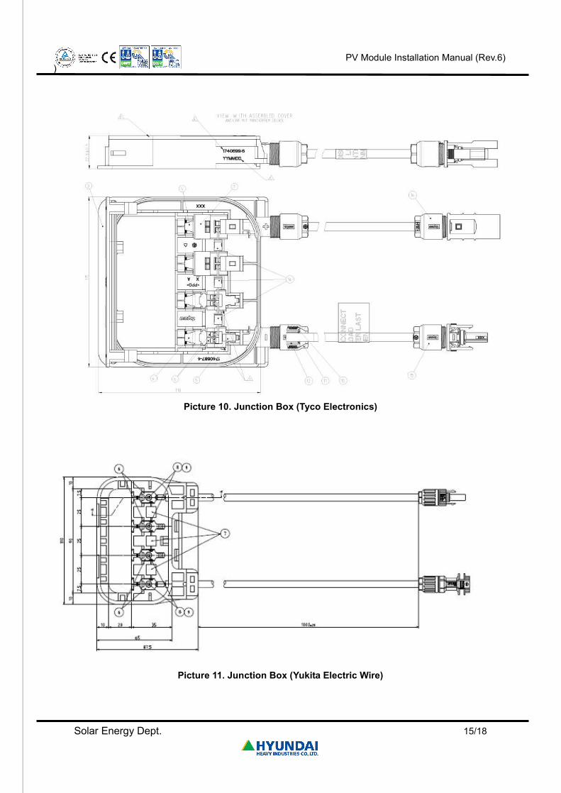
Picture 10. Junction Box (Tyco Electronics)
Picture 11. Junction Box (Yukita Electric Wire)
Page 16
PV Module Installation Manual (Rev.6)
)
Solar Energy Dept. 16/18
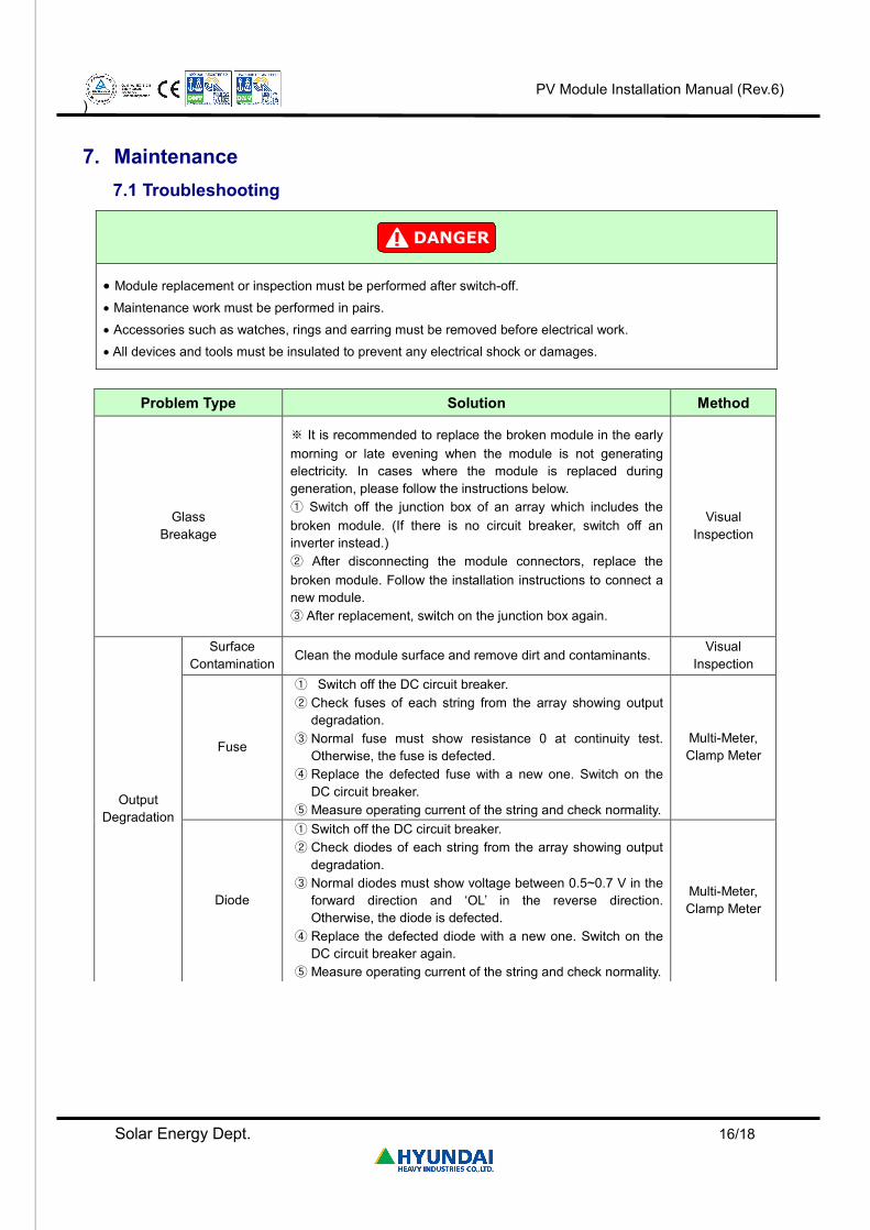
7. Maintenance 7.1 Troubleshooting
· Module replacement or inspection must be performed after switch-off.
· Maintenance work must be performed in pairs.
· Accessories such as watches, rings and earring must be removed before electrical work.
· All devices and tools must be insulated to prevent any electrical shock or damages.
Problem Type Solution Method
Glass Breakage
※ It is recommended to replace the broken module in the early morning or late evening when the module is not generating electricity. In cases where the module is replaced during generation, please follow the instructions below. ① Switch off the junction box of an array which includes the broken module. (If there is no circuit breaker, switch off an inverter instead.) ② After disconnecting the module connectors, replace the broken module. Follow the installation instructions to connect a new module. ③ After replacement, switch on the junction box again.
Visual Inspection
Output Degradation
Surface Contamination
Clean the module surface and remove dirt and contaminants. Visual
Inspection
Fuse
① Switch off the DC circuit breaker. ② Check fuses of each string from the array showing output
degradation. ③ Normal fuse must show resistance 0 at continuity test.
Otherwise, the fuse is defected. ④ Replace the defected fuse with a new one. Switch on the
DC circuit breaker. ⑤ Measure operating current of the string and check normality.
Multi-Meter, Clamp Meter
Diode
① Switch off the DC circuit breaker. ② Check diodes of each string from the array showing output
degradation. ③ Normal diodes must show voltage between 0.5~0.7 V in the
forward direction and ‘OL’ in the reverse direction. Otherwise, the diode is defected.
④ Replace the defected diode with a new one. Switch on the DC circuit breaker again.
⑤ Measure operating current of the string and check normality.
Multi-Meter, Clamp Meter
Page 17
PV Module Installation Manual (Rev.6)
)
Solar Energy Dept. 17/18
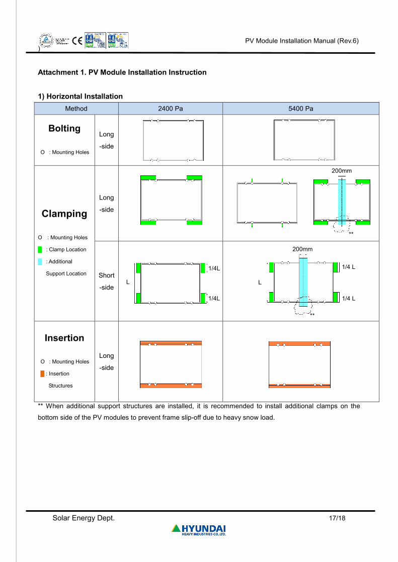
Attachment 1. PV Module Installation Instruction 1) Horizontal Installation
Method 2400 Pa 5400 Pa
Bolting
O : Mounting Holes
Long
-side
Clamping
O : Mounting Holes
█ : Clamp Location
█ : Additional
Support Location
Long
-side
Short
-side
Insertion
O : Mounting Holes
█ : Insertion
Structures
Long
-side
** When additional support structures are installed, it is recommended to install additional clamps on the
bottom side of the PV modules to prevent frame slip-off due to heavy snow load.
1/4L
1/4L
L
1/4 L
1/4 L
L
**
200mm
**
200mm
Page 18
PV Module Installation Manual (Rev.6)
)
Solar Energy Dept. 18/18
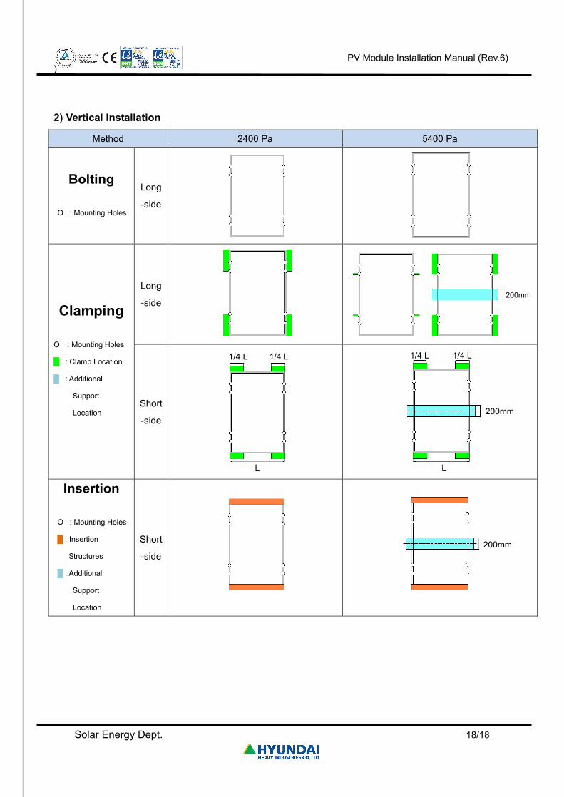
2) Vertical Installation
Method 2400 Pa 5400 Pa
Bolting
O : Mounting Holes
Long
-side
Clamping
O : Mounting Holes
█ : Clamp Location
█ : Additional
Support
Location
Long
-side
Short
-side
Insertion
O : Mounting Holes
█ : Insertion
Structures
█ : Additional
Support
Location
Short
-side
1/4 L 1/4 L
L
1/4 L 1/4 L
200mm
L
200mm
200mm