24
Installation, Operation, and Parts Manual TS10A, LPG Electronic Wave Form Pulser
Installation, Operation, and Parts Manual
TS10A, LPG ElectronicWave Form Pulser

P (800) 634-2695 • (260) 747-7524
F (800) 866-4861
8825 Aviation Drive Fort Wayne, Indiana 46809
Manufacturing Facility located in Fort Wayne, IN
Our manufacturing facility is ISO 9001:2008 and Atex Certified
Principle of Operation............................................................................3Safety Procedures.................................................................................4Installation and Operations ...............................................................5-7Torque and Wrench Chart....................................................................6Wiring Diagrams and Control Drawings..........................................7-11Meter Maintenance.........................................................................12-14 Meter Disassembly ..................................................14-15 Differential Valve............................................................18 Strainer...........................................................................17 Inlet Check Valve............................................................18 Vapor Eliminator.............................................................17Parts List : Flow Meter.......................................................................16 Differential Valve............................................................ 19 Strainer...........................................................................17 Inlet Check Valve............................................................18 Vapor Eliminator.............................................................17Mounting and Dimensions...................................................................19Troubleshooting.. . . . . . . . . . . . . . . . . . . . . . . . . . . . . . . . . . . . . . . . . . . . . . . . . . . . . . . . .20SCL (Pulser Assembly) ................................................................... 21 - 22Meter Maintenance and Calibration Records ..................................... 23
Tuthill Corporations humble beginnings date back to 1892, when James B. Tuthill purchased a clay quarry and a kiln and began supplying Chicago common bricks to local construction firms. In the early 1920’s, his efforts to improve lifting clay from the quarry turned up a new transportation idea—a steam-powered truck engine.
The design eventually proved unworkable, but Tuthill recognized the value of the engine’s small, internal gear pump, which injected fuel oil directly into the truck boiler. The pump design was refined and was marketed to companies that produced oil-fired boilers for use in residential and industrial heating, where it enjoyed great success and formed the basis on which the Tuthill Pump Company was formed.
Over 120 years and five generations later, Tuthill Corporation is a global presence in vacuum pumps, blowers, plastics, and fuel and chemical transfer systems. We take great pride in our “Made in USA” moniker, making quality and durability top priorities. Tuthill Precision Meters carry that legacy and competency in fluid transfer products to new levels. Our patented “Wave Form” gears provide extreme accuracy through strict control of fluid slippage in the metering chamber, and our electronics work with virtually any metering or management system.
Your choice of a Tuthill Precision Meter is an investment in professional equipment that will pay dividends for years to come. We appreciate your business, and look forward to serving you in the future!
About Tuthill Meters We thank you for purchasing a Tuthill Meter for liquid measurement service. Tuth i l l Meters , formerly Fluid Power Products, is now a trade name of Tuthill Transfer Systems. Fluid Power Products was established in 1980. Since its inception, the company has been dedicated to manufacturing cost-effective, high performance flow metering devices for petroleum, industrial, commercial and municipal service.
Our facilities include computerized order entry and inventory control, so that you are assured of accurate and prompt de-liveries. Furthermore, our production personnel ensure that each order, regardless of size, receives individual attention.
Constant attention to new product development and produc-tion design, our high standards of manufacture and final testing are the reasons why Tuthill Meters meet your most demanding requirements. With the ‘Waveform’ oval gear (2003 patent) meter accuracy is better than ever before.
Our meters are used in batching, blending, process control and to dispense fluids in liquid handling facilities throughout the World. Service includes gasohol blends, bio-diesel, LPG and special formulation racing fuels.
Principle of OperationPositive Displacement meters have a measuring chamber, where inlet & outlet are separated by rotors, a rotating element or sliding vanes. As the liquid passes through the flow meter, it causes the rotors/element/vanes to turn, which forms the basis for volumetric measurement.
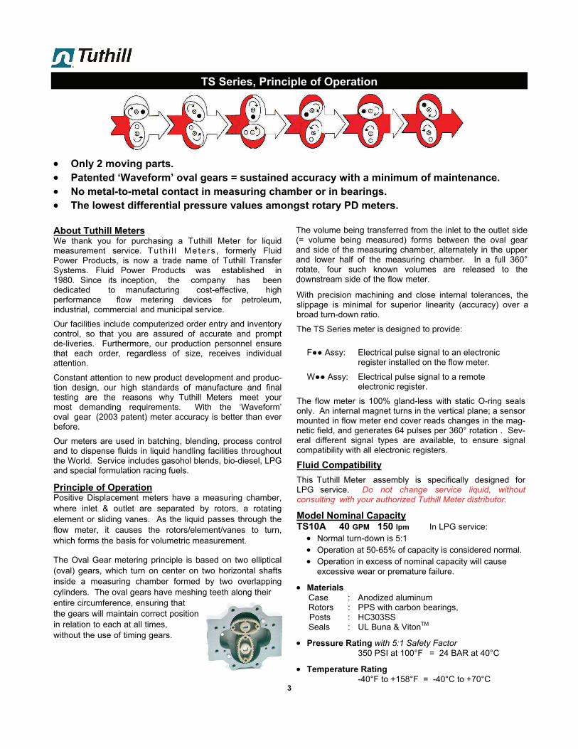
The Oval Gear metering principle is based on two elliptical (oval) gears, which turn on center on two horizontal shafts inside a measuring chamber formed by two overlapping cylinders. The oval gears have meshing teeth along theirentire circumference, ensuring thatthe gears will maintain correct positionin relation to each at all times,without the use of timing gears.
The volume being transferred from the inlet to the outlet side (= volume being measured) forms between the oval gear and side of the measuring chamber, alternately in the upper and lower half of the measuring chamber. In a full 360° rotate, four such known volumes are released to the downstream side of the flow meter..
With precision machining and close internal tolerances, the slippage is minimal for superior linearity (accuracy) over a broad turn-down ratio.
The TS Series meter is designed to provide:
F●● Assy: Electrical pulse signal to an electronic register installed on the flow meter.
W●● Assy: Electrical pulse signal to a remote electronic register.
The flow meter is 100% gland-less with static O-ring seals only. An internal magnet turns in the vertical plane; a sensor mounted in flow meter end cover reads changes in the mag-netic field, and generates 64 pulses per 360° rotation . Sev-eral different signal types are available, to ensure signal compatibility with all electronic registers.
Fluid Compatibility
This Tuthill Meter assembly is specifically designed for LPG service. Do not change service liquid, without consulting with your authorized Tuthill Meter distributor.
Model Nominal Capacity TS10A 40 GPM 150 lpm In LPG service: Normal turn-down is 5:1 Operation at 50-65% of capacity is considered normal. Operation in excess of nominal capacity will cause
excessive wear or premature failure.
MaterialsCase : Anodized aluminum
Rotors : PPS with carbon bearings, Posts : HC303SS
Seals : UL Buna & VitonTM
Pressure Rating with 5:1 Safety Factor350 PSI at 100°F = 24 BAR at 40°C
Temperature Rating-40°F to +158°F = -40°C to +70°C
3
TS Series, Principle of Operation
Only 2 moving parts. Patented ‘Waveform’ oval gears = sustained accuracy with a minimum of maintenance. No metal-to-metal contact in measuring chamber or in bearings. The lowest differential pressure values amongst rotary PD meters.
4
Read this manual as well as the literature provided in your
owner’s manual. If you have any questions, consult with
your full-service distributor or call the Service Department at
Tuthill at 260-747-7524 or 800-634-2695.
Please have the following information available when you
make inquiries, order replacement parts, or schedule ser-
vice. If a specific meter accessory is involved, please pro-
vide the model and serial number of the accessory in ques-
tion.
Meter Serial No.: ____________________________
Your Full Service Distributor:
Name: ________________________________
Telephone: _________________________________
IN THE EVENT OF A GAS LEAK In the event of a large gas leak:
Evacuate the area and notify the fire department or
other appropriate authorities.
In the event of a small, contained gas leak:
Isolate and stop the leak
Prevent accidental ignition
Prevent entrance of gas into other portions of the
building. Be aware that LPG is heaver than air and
will seek lower levels
Evacuate all people from the danger zone
See that the gas is dispersed before resuming the
business and operations. If in doubt, notify your
local authorities.
IN THE EVENT OF A GAS FIRE In the event of large fires or fires that are spreading:
Evacuate the building and notify your local fire department.
Stop the leakage only if you can safely reach the equipment.
In the event of small, contained fires that you can safely
control:
Stop the leakage if you can safely reach the equipment.
Then use the appropriate extinguisher: Class B fire extin-
guisher, water, fog, etc. depending on the equipment. If in
doubt, call your local fire department.
Safety Procedures
This manual provides warnings and procedures that are intended to inform the owner/operator of the
hazards present when using the Tuthill Meters and other products. The reading of these warnings
and the avoidance of such hazards is strictly in the hands of the owner/operator of the equipment. Neglect
of that responsibility is not within the control of the manufacturer of the flow meter.
The meters non-shock maximum operating pressure is
indicated on the meter name plate. The meter should
never be operated in excess of this pressure. Care should
be taken to eliminate thermal and hydraulic shock pres-
sures, so that they do not exceed the meters maximum
working pressure.

5
Installation & Operation
Installation (also see page 12):
Positive Displacement meters are designed to operate full
of liquid. The meter should be installed in a manner, so
that it remains full of liquid at all times.
Hydraulic shock can be harmful to flow meter and
other system components. Consideration to elimi-
nate hydraulic shock should be given in selection of
pump and design of the piping system.
In critical installation, block valves and by-pass lines
are recommended. This allows the meter to be ser-
viced without interruption of flow in a critical process
application.
Thermal and or over pressure relief valves are rec-
ommended and should be installed whenever it is
possible to block (isolate) the meter between two
valves. Thermal pressures many times the operating
pressure are possible with only a small rise in tem-
perature.
Protective caps installed in flow meter flanges prior to
shipment should remain in place until you are ready to
install in the piping system.
Keep all external surfaces of the meter clean.
It is recommended that a Strainer be installed upstream
of each flow meter, to prevent damage from foreign mat-
ter, such as welding slag, pipe scale or parts breaking off
other equipment. When using Tuthill right-angle strainer:
Inlet can be either from the front or the rear of the
strainer (inlet flange & strainer basket cover have same
bolt pattern, and can be reversed in the field).
Allow adequate space for removal of strainer basket
cover, so strainer basket can be cleaned.
Strainer basket comes standard with 200 mesh for
LPG (Propane) service.
Flush the system with a liquid compatible with the flow
meter to remove all debris, scale and welding slag prior
to flow meter installation.
If this is not possible, temporarily remove rotors (oval
gears), and reinstall after the system has been flushed.
Apply pipe compound to male threads, to install the two
companion flanges. Tighten to a position, that allows
the meter to bolt to the companion flanges, free of pipe
stress.
The meter should always be supported by bolting
firmly to a solid platform or foundation. Never use the
connecting pipe as the means of support.
When installing the flow meter, consider future mainte-
nance of both flow meter and accessories. The meter
can be serviced in place, provided block (isolation) valves
are included, and adequate space allowed.
OPERATING TEMPERATURE TS Series W●● & F●● assemblies are rated for opera-
tion from -40°F/+257°F (-40°C/+125°C), subject to possi-
bly tighter ratings applicable to the electronic register.
OPERATING PRESSURE Maximum non-shock Operating Pressure is:
350 PSI (24 BAR) at 100°F (= 38°C)
The flow meter should never be operated in excess of this
pressure. Care should be taken to eliminate thermal and
hydraulic shock conditions, so that system pressure never
exceeds Maximum Working Pressure rating.
SAFETY INSTRUCTIONS Make sure that all necessary safety precautions have been
taken, including proper clothing, personal safety equipment
and fire safety equipment if required.
Before Start-Up of the Flow Meter, make certain that:
1. The meter is properly mounted, secured and piped.
2. All connections are tight.
3. All bleed and drain valves are closed.
4. Do NOT smoke near meter, or use meter near an open
flame, when metering flammable liquids. Fire or Explo-
sion could result.
Install the Flow Meter and Accessories in compliance
with all applicable Local, State & Federal Construction,
Electrical and Safety Codes. Additionally LPG meters
must be installed in accordance with the requirements
of ANSI-NFPA 58.
Follow the manufacturer’s recommendation fully when in-
stalling pumps. Give particular attention to factors like: use
of foot valves, pipe size to the inlet and conformance to net
positive suction head (NPSH) conditions when suction
pumping is required. Following the manufactures’ recom-
mendations will minimize air and vapor elimination prob-
lems.
Start-Up:
Fill the system slowly to avoid operation on air or vapor.
This can be accomplished in the following manner:
Throttle the meter inlet valve, and allow the meter and pip-
ing to fill slowly by gravity.
Crack open the outlet valve and start the pump, then slowly
open the inlet valve until the system is up to pressure. Open
the outlet valve fully to establish full flow. Check the flow
rate to assure the meter is operating within specified rates.
The meter is not designed to operate on air, but the design
and materials of construction of the Tuthill Meter allows for
operation on vapor for short periods of time without damage
to the elliptical gears or other meter internals.
Note: Overspeeding and hammer caused by the
presence of vapor in the system can cause
internal damage to the meter.
6
Installation, Start-Up & Operation
The Vapor Eliminator is included in the flow meter as-
sembly, with one vent port connected to differential valve
(or 3-way solenoid valve, when included). The other vent
port must be piped back to storage.
Connections for calibration should be provided during
installation. An easy means for diverting flow into a cali-
bration vessel (or master meter) should be considered.
Refer to Tuthill Technical Manual for a diagram of the
sug-gested installation.
Operation Requirements:
Upstream lines must be maintained full to prevent air/vapors
from entering the meter. If the upstream or inlet lines are
constructed in a manner which allows reverse flow, foot or
back check valves should be installed.
Underground tanks that are furnished with a submersible
pump will eliminate many problems that occur with positive
displacement pumps with suction pipes, when the suction
piping is incorrectly sized creating too large a lift.
Every meter should be calibrated under actual service and
installation conditions. Follow your local Weights and Meas-
ures recommendations.
Give careful attention to your system’s pumping equipment
and piping, because of their influence on the liquid being
measured as it enters the meter assembly. Systems should
be designed free of conditions that cause or introduce en-
trained air or vapor.
Torque Chart

7
Installation & Operation continued
A. EL0304 Terminal Block Board (TBB)
EL0305 TBB/AmplifierEL0305 is used for remote high frequency electronicregisters accepting quadrature signal, when the cabledistance is in 200-600’ (60-180 m) range.
For greater distances external amplifier (2xPIA-300) isrequired.
Pulser cable plugs into: J1 on EL0304 AMP on EL0305
Signal output cable is connected to TB1
B. EL0304 to EMR³ RegisterEL0305 TBB/Amplifier to EMR³ Register Pulser cable plugs into: J1 on EL0304 AMP on EL0305
Signal output cable is connectedto TB1

8
Installation & Operation continued
C. EL0300 Scaler/Calibrator/Linearizer (SCL)While the SCL can have multiple functions, in manycases it is included strictly as a signal conditioner(= ‘Jitter filter’). In those cases, only the calibratorfunction is active.
Pulser plug is removed. Pulser leads are connecteddirectly to TB2 on the SCL.
Signal output cable is connected to TB1.
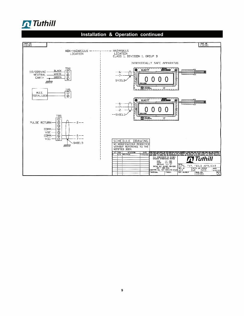
This diagram applies to the ELNC register, when the flow meter/register are used in non-hazardous zone.
It also applies to LectroCount™ and other lower fre-quency registers with quadrature input.
D. EL0300 (SCL), EL2057 Energy Limited Power Supply (ELPS) & ELNC RegisterWhen flow meter/ELNC register isused in a hazardous zone, theEL2057 (AC/DC power supply &barrier, UL listed) must be used.EL2057 is in a NEMA 7 enclosure(Expl-Proof, but not water proof),so it must be installed under roofor inside a water proof cabinet.
Pulser plug is removed. Pulserleads are connected directly toTB2 on the SCL.
Signal output cable is con-nected to TB1.
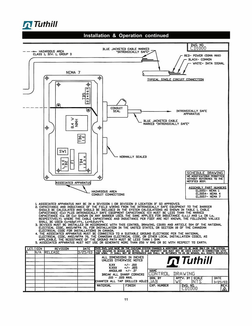
Note 1 : See CD1000 & CD1001 for installation of intrinsically safe apparatus. Note 2 : Cable lengths are limited by entity parameters. Note 3 : ELPS output option: Install U1, R3 & TB6.
E. EL0300 to non-Quadrature RegisterSame as diagram D, but connect only signal channel A.
SCL is not yet approved for use in the EU.
W1: 1 pin exposed = 5.5-12VDC non-regulated
W1: Both pins covered = 5VDC regulated
EL0300-3-XXY: W1 installed = 5VDC regulated W1 removed = 5.5-12VDC
EL0300-5-XXY: standard = 24VDC
9
Installation & Operation continued

10
Installation & Operation continued
11
Installation & Operation continued

Vent Line: The vent line from the meter’s vapor vent to the vapor space
on the supply tank should a minimum of 1/4” inside diameter
tube or pipe. A shutoff valve must be installed in the vapor
vent line to allow removal of the strainer or service on the
meter. The vapor release vent line must be returned to the
vapor space of the supply tank and normally should not be
made common with the other vapor return lines or pump by-
pass lines. When properly installed, this line must permit
free flow in either direction. If the vent line is closed the me-
ter will not function, as the differential valve will not open.
These instructions must be followed to maintain proper func-
tion of the differential valve.
Support: Prevent pipe strain or stress from occurring when making
connections to meter or accessories and during repairs.
Pipe strain and stress occurs when the pipes are not sup-
ported or are not aligned correctly to the meter. The weight
of the pipes must always be supported independent of the
meter. This meter and accessories can easily be removed
without affecting the pipes or the pipe alignment. Never
leave any of the pipes hinging.
12
Calibration
Theory of Operation; The Tuthill Meter LPG metering system combines an oval gear positive displacement meter, differential valve, strainer and vapor eliminator in one assembly. The differential valve incorporates a piston type construction with the piston mov-ing away from its seat when at least 15 PSI pressure (above product vapor pressure) is maintained at the meter outlet. The soft seat valve assures measurement accuracy by re-quiring pump operation for delivery, by requiring adequate back pressure to prevent product vaporization during meas-urement and by requiring blockage of flow when the vapor eliminator release valve is open. The strainer prevents for-eign particulate from entering and damaging the meter. The meters close tolerance machine construction and no metal to metal contact provides accurate liquid measurement.
Installation on a Truck:
Flow Meter: Install the meter assembly in a dispenser cabinet, or a truck
deck to a secure base using the bolt holes on the “feet” of
the strainer assembly base. Make inlet and outlet connec-
tions at the flanged surfaces on the strainer and differential
valve, respectively. Leave a minimum of 12 inches be-
tween he strainer flange and any obstacle for servicing
the strainer.
Flow meter can be TS06A (as shown in diagram), or model TS10A = straight-through, where the back-check/differential valve is mounted with outlet facing down.
and scratches.
Repair pulled threads with threaded insert fasteners.These can be used in many instances. Contact your full-service distributor for advice if this occurs.
Coating threads: When removing and replacing bolts andscrews in a meter, always coat the threads with anti-seize.
Removing flange seals: When removing the flange as-sembly, always carefully remove the O-ring seal. Makesure that the flange surface is clean. Discard and replacethe old O-ring seals if it is nicked or scratched in any way.It is undamaged, it can be re-used.
Examine all fasteners: make sure fasteners are not bent,rusted, or have pulled or burred threads. The threadsshould all appear evenly placed. If the bolts are bent,check the housing and cover for flatness. Use a straightedge to determine flatness. Use a stone to remove anyburrs on the flat surfaces for the housing.
Look for gaps: When disassembling a meter, use a feelergauge to check for gaps between the post and gearplates and housing. If you do find gaps, check the platesfor flatness with a straight edge. Gaps can be caused byshock problems that must be resolved. Contact your fullservice distributor, or the Service Department atTuthill Meters for assistance if this occurs.
Check the O-Rings: O-rings should be smooth. Crackedor worn O-rings should be replaced. However, a moreserious problem of shock my have occurred if the O-ringsare nibbled or extruded. Shock problems must be verifiedand resolved. Contact your full service distributor, or theService Department at Tuthill Meters for assistance ifthis occurs.
Check the post and gear plates: Check the plates forflatness. Use a straight edge. Warped plates can becaused by hydraulic shock problems that must be re-solved. Contact your full service distributor, or the Ser-vice Department at Tuthill Meters for assistance if thisoc-curs.
Weights & Measures: Check with the regulatory agencythat governs Weights and Measures in your area. Re-moving a seal wire may require Weight & Measures re-calibration.
13
Meter Maintenance
Storage: If the meter is used for seasonal work, at the end of each
season the meter should be removed from the system and
thoroughly flushed with a compatible liquid. This includes
removing the drain on the front and rear covers. Then flush
the product from the front and rear covers. If flushing with
water is preferred, extra care should be taken to drain the
meter completely and to dry all internal parts. Immediate
refilling with a compatible liquid (or oil misting) is essential to
prevent corrosion as well as ice damage to parts from mois-
ture that was overlooked after flushing and drying.
Preparing for Service:
Close the belly valve of the supply tank.
Close the valve on the vapor return line.
Close the manual valve in the supply line on the inlet sideof the meter. If no manual valve exists on the inlet side,consult the bobtail manufacturer or service provider/installer for procedures to depressurize the system.
Slowly open the valve/nozzle on the end of the supply line
After product is bled off, close the valve/nozzle at the endof the supply line.
Open the bleed valve provided by your installer to relievethe system pressure. Product will drain from the metersystem.
As product is bleeding from the bleed valve, slowly re-open and close the valve/nozzle on the discharge line.Repeat this step until the product stops draining from thebleed valve and discharge line valve/nozzle.
Leave the discharge line valve/nozzle open while workingon the system.
General Service:
Do not scratch or mar any of the precision machined sur-faces by prying or sanding parts.
Torque specifications. All fasteners such as screws andbolts should be torqued to proper specifications. See the“Torque Chart” in this manual.
Stone the machined surfaces when reassembling themeter to assure the machined surfaces are free of burrs
Relieve all internal pressure before servicing. Line pressure must be 0.0 PSI
Serious injury or death from fire or explosion could result from maintenance
of an improperly de-pressurized and evacuated system.
Danger!! Danger!! Danger!!
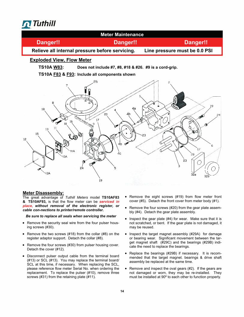
Remove the eight screws (#19) from flow meter frontcover (#5). Detach the front cover from meter body (#1).
Remove the four screws (#20) from the gear plate assem-bly (#4). Detach the gear plate assembly.
Inspect the gear plate (#4) for wear. Make sure that it isnot scratched, or bent. If the gear plate is not damaged, itmay be reused.
Inspect the target magnet assembly (#29A) for damageor bearing wear. Significant movement between the tar-get magnet shaft (#29C) and the bearings (#29B) indi-cate the need to replace the bearings.
Replace the bearings (#29B) if necessary. It is recom-mended that the target magnet. bearings & drive shaftassembly be replaced at the same time.
Remove and inspect the oval gears (#2). If the gears arenot damaged or worn, they may be re-installed. Theymust be installed at 90º to each other to function properly.
14
Meter Maintenance
Meter Disassembly: The great advantage of Tuthill Meters model TS10AF83 & TS10AF93, is that the flow meter can be serviced in place, without removal of the electronic register, or cable con-nections to printer/remote controller.
Be sure to replace all seals when servicing the meter
Remove the security seal wire from the four pulser hous-ing screws (#30).
Remove the two screws (#18) from the collar (#8) on theregister adaptor support. Detach the collar (#8).
Remove the four screws (#30) from pulser housing cover.Detach the cover (#12).
Disconnect pulser output cable from the terminal board(#13) or SCL (#13). You may replace the terminal board/SCL at this time, if necessary. When replacing the SCL,please reference flow meter Serial No. when ordering thereplacement. To replace the pulser (#10), remove threescrews (#31) from the retaining plate (#11).
Relieve all internal pressure before servicing. Line pressure must be 0.0 PSI
Danger!! Danger!! Danger!!
Exploded View, Flow Meter
TS10A W83: Does not include #7, #8, #18 & #26. #9 is a cord-grip.
TS10A F83 & F93: Include all components shown
Pulser output cable

it is recommended that the flow meter be replaced.
Reinstall the meter gear plate (#4).
Reinstall the cover (#5).
It is recommended that all O-rings and seals be replacedduring service. If seals are reused, a good inspection iscritical.
Reinstall the pulser (#10) and terminal board/SCL (#13) ifnecessary. Reconnect pulser output cable.
Reinstall the pulser housing cover plate (#12) on frontcover (#5). Replace the pulser cover “O” ring if neces-sary. A small amount of petroleum jelly may be used tohelp hold the “O” ring (#15) in place while re-installing.
Fill the flow meter with gas, and inspect for leaks
15
Meter Maintenance
Inspect the post plate and posts. Replace if there is anywear or scratches on the post plate. A small amount ofpolishing (surface marking) on the post plate (#3) is nor-mal. If the polishing results in an indentation or groovesin the surface, replace the post plate assembly.
Inspect the meter body for damage. Use 200 grit paperto remove small scratches and blemishes, if the damageis more than superficial, replace the body.
Clean all surfaces using a brush or fine (200 grit) emerycloth to remove small scratches or deposits. IF THEREARE LARGE SCRATCHES OR DAMAGE THAT CANCREATE A LEAK PATH, REPLACE THE PART.
Rotate the oval gears (#2) on the posts and insure thatthere are no rubs between the gears and the body (#1).A Rub would indicate a bent post or a bent post plateassembly (#3). If this occurs, replace the post plate as-sembly (#3).
The expectations would be, that the post plate assembly(#3) should be replaced with each second or third set ofgears depending on service conditions (flow rate & totalvolume).
Install a new oval gear set (#2) if necessary. Gearsshould be perpendicular to each other. The gears will notrotate a complete revolution if not installed properly.Once installed, the gears should rotate freely, withoutbinds or rubs.
Check clearances between the gears and the body (#1).There should be a minimum of .003 inch (0.076 mm)between gears (#2) and the gear plate (#4). If there isany binds or rubs between the gears and the meter body,
Pulser output cable
16
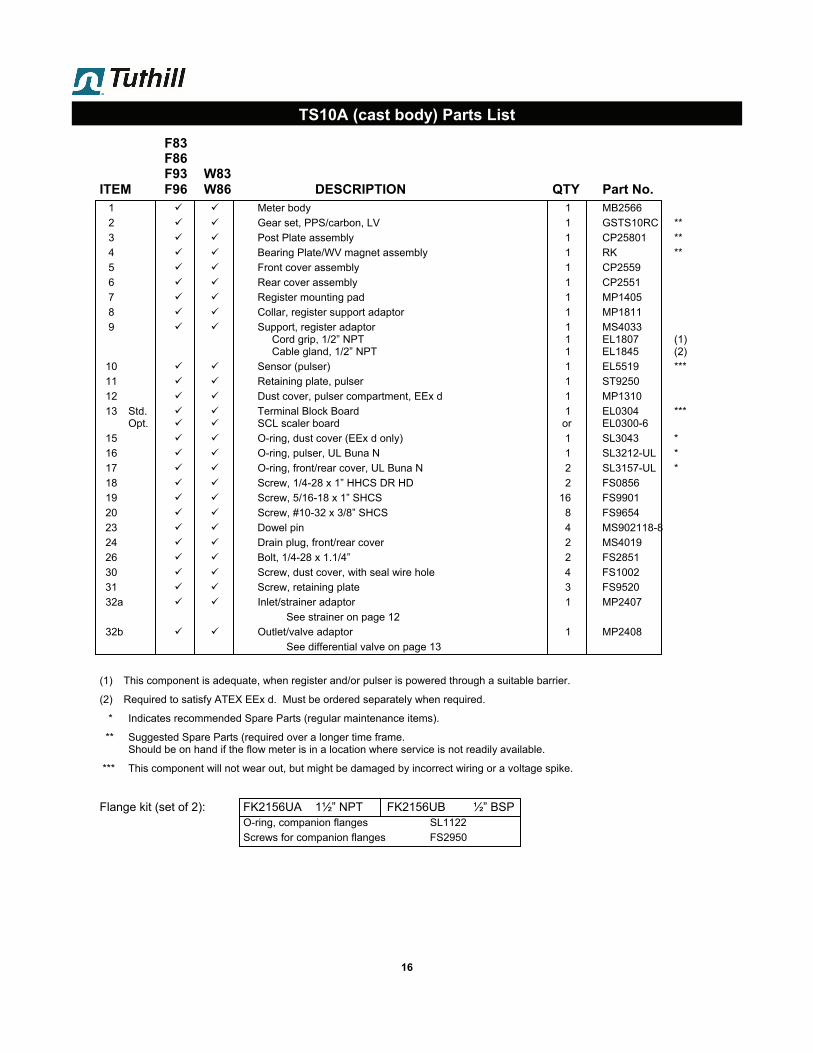
TS10A (cast body) Parts List
F83 F86 F93 W83
ITEM F96 W86 DESCRIPTION QTY Part No. 1 Meter body 1 MB2566
2 Gear set, PPS/carbon, LV 1 GSTS10RC **
3 Post Plate assembly 1 CP25801 **
4 Bearing Plate/WV magnet assembly 1 RK **
5 Front cover assembly 1 CP2559
6 Rear cover assembly 1 CP2551
7 Register mounting pad 1 MP1405
8 Collar, register support adaptor 1 MP1811
9 Support, register adaptor 1 MS4033 Cord grip, 1/2” NPT 1 EL1807 (1) Cable gland, 1/2” NPT 1 EL1845 (2)
10 Sensor (pulser) 1 EL5519 ***
11 Retaining plate, pulser 1 ST9250
12 Dust cover, pulser compartment, EEx d 1 MP1310
13 Std. Terminal Block Board 1 EL0304 *** Opt. SCL scaler board or EL0300-6
15 O-ring, dust cover (EEx d only) 1 SL3043 *
16 O-ring, pulser, UL Buna N 1 SL3212-UL *
17 O-ring, front/rear cover, UL Buna N 2 SL3157-UL *
18 Screw, 1/4-28 x 1” HHCS DR HD 2 FS0856
19 Screw, 5/16-18 x 1” SHCS 16 FS9901
20 Screw, #10-32 x 3/8” SHCS 8 FS9654
23 Dowel pin 4 MS902118-8
24 Drain plug, front/rear cover 2 MS4019
26 Bolt, 1/4-28 x 1.1/4” 2 FS2851
30 Screw, dust cover, with seal wire hole 4 FS1002
31 Screw, retaining plate 3 FS9520
32a Inlet/strainer adaptor 1 MP2407
See strainer on page 12
32b Outlet/valve adaptor 1 MP2408
See differential valve on page 13
(1) This component is adequate, when register and/or pulser is powered through a suitable barrier.
(2) Required to satisfy ATEX EEx d. Must be ordered separately when required.
* Indicates recommended Spare Parts (regular maintenance items).
** Suggested Spare Parts (required over a longer time frame. Should be on hand if the flow meter is in a location where service is not readily available.
*** This component will not wear out, but might be damaged by incorrect wiring or a voltage spike.
Flange kit (set of 2): FK2156UA 1½” NPT FK2156UB ½” BSP O-ring, companion flanges SL1122
Screws for companion flanges FS2950
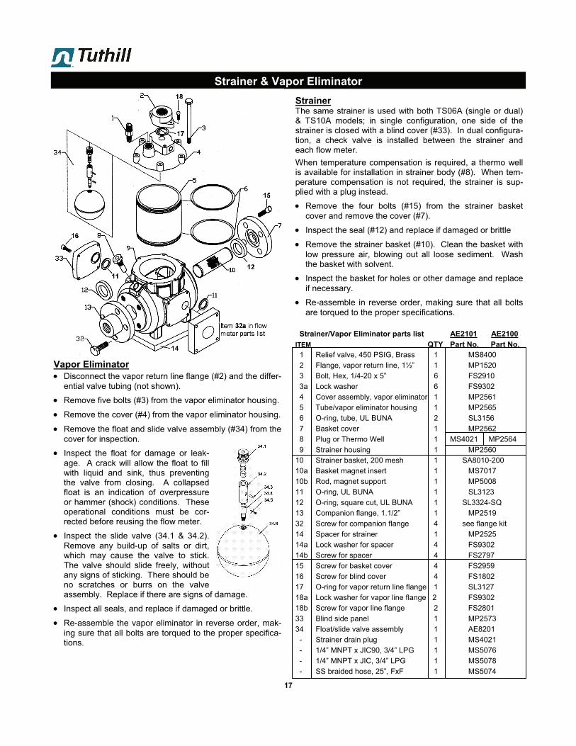
Strainer The same strainer is used with both TS06A (single or dual) & TS10A models; in single configuration, one side of the strainer is closed with a blind cover (#33). In dual configura-tion, a check valve is installed between the strainer and each flow meter.
When temperature compensation is required, a thermo well is available for installation in strainer body (#8). When tem-perature compensation is not required, the strainer is sup-plied with a plug instead.
Remove the four bolts (#15) from the strainer basketcover and remove the cover (#7).
Inspect the seal (#12) and replace if damaged or brittle
Remove the strainer basket (#10). Clean the basket withlow pressure air, blowing out all loose sediment. Washthe basket with solvent.
Inspect the basket for holes or other damage and replaceif necessary.
Re-assemble in reverse order, making sure that all boltsare torqued to the proper specifications.
Strainer/Vapor Eliminator parts list AE2101 AE2100
ITEM QTY Part No. Part No. 1 Relief valve, 450 PSIG, Brass 1 MS8400
2 Flange, vapor return line, 1½” 1 MP1520
3 Bolt, Hex, 1/4-20 x 5” 6 FS2910
3a Lock washer 6 FS9302
4 Cover assembly, vapor eliminator 1 MP2561
5 Tube/vapor eliminator housing 1 MP2565
6 O-ring, tube, UL BUNA 2 SL3156
7 Basket cover 1 MP2562
8 Plug or Thermo Well 1 MS4021 MP2564
9 Strainer housing 1 MP2560
10 Strainer basket, 200 mesh 1 SA8010-200
10a Basket magnet insert 1 MS7017
10b Rod, magnet support 1 MP5008
11 O-ring, UL BUNA 1 SL3123
12 O-ring, square cut, UL BUNA 1 SL3324-SQ
13 Companion flange, 1.1/2” 1 MP2519
32 Screw for companion flange 4 see flange kit
14 Spacer for strainer 1 MP2525
14a Lock washer for spacer 4 FS9302
14b Screw for spacer 4 FS2797
15 Screw for basket cover 4 FS2959
16 Screw for blind cover 4 FS1802
17 O-ring for vapor return line flange 1 SL3127
18a Lock washer for vapor line flange 2 FS9302
18b Screw for vapor line flange 2 FS2801
33 Blind side panel 1 MP2573
34 Float/slide valve assembly 1 AE8201
- Strainer drain plug 1 MS4021
- 1/4” MNPT x JIC90, 3/4” LPG 1 MS5076
- 1/4” MNPT x JIC, 3/4” LPG 1 MS5078
- SS braided hose, 25”, FxF 1 MS5074
17
Strainer & Vapor Eliminator
Vapor Eliminator Disconnect the vapor return line flange (#2) and the differ-
ential valve tubing (not shown).
Remove five bolts (#3) from the vapor eliminator housing.
Remove the cover (#4) from the vapor eliminator housing.
Remove the float and slide valve assembly (#34) from thecover for inspection.
Inspect the float for damage or leak-age. A crack will allow the float to fillwith liquid and sink, thus preventingthe valve from closing. A collapsedfloat is an indication of overpressureor hammer (shock) conditions. Theseoperational conditions must be cor-rected before reusing the flow meter.
Inspect the slide valve (34.1 & 34.2).Remove any build-up of salts or dirt,which may cause the valve to stick.The valve should slide freely, withoutany signs of sticking. There should beno scratches or burrs on the valveassembly. Replace if there are signs of damage.
Inspect all seals, and replace if damaged or brittle.
Re-assemble the vapor eliminator in reverse order, mak-ing sure that all bolts are torqued to the proper specifica-tions.
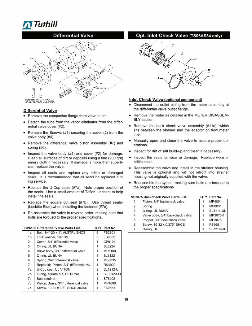
Inlet Check Valve (optional component) Disconnect the outlet piping from the meter assembly at
the differential valve outlet flange.
Remove the meter as detailed in the METER DISASSEM-BLY section.
Remove the back check valve assembly (#11a), whichsits between the strainer and the adaptor on flow meterinlet.
Manually open and close the valve to assure proper op-erations.
Inspect for dirt of salt build-up and clean if necessary.
Inspect the seals for wear or damage. Replace worn orbrittle seals.
Reassemble the valve and install in the strainer housing.This valve is optional and will not retrofit into strainerhousing not originally supplied with the valve.
Reassemble the system making sure bolts are torqued tothe proper specifications
VP3075 Backcheck Valve Parts List QTY Part No. 1 Piston, 3/4” backcheck valve 1 MP4001
2 Spring 1 MS8031
3 O-ring, UL BUNA 1 SL3114-UL
4 Valve body, 3/4” backcheck valve 1 MP3075-1
5 Poppet, 3/4” backcheck valve 1 MP3076
6 Screw, 10-32 x 0.375” SHCS 1 FS9651
7 O-ring, UL 1 SL3218-UL
18
Differential Valve
Differential Valve Remove the companion flange from valve outlet.
Detach the tube from the vapor eliminator from the differ-ential valve cover (#2).
Remove the Screws (#1) securing the cover (2) from thevalve body (#4).
Remove the differential valve piston assembly (#7) andspring (#6).
Inspect the valve body (#4) and cover (#2) for damage.Clean all surfaces of dirt or deposits using a fine (200 grit)emery cloth if necessary. If damage is more than superfi-cial, replace the valve.
Inspect all seals and replace any brittle or damagedseals. It is recommended that all seals be replaced dur-ing service.
Replace the U-Cup seals (#7a). Note proper position ofthe seals. Use a small amount of Teflon lubricant to helpinstall the seals.
Replace the square cut seal (#7b). Use thread sealer(Locktite Blue) when installing the fastener (#7e).
Re-assemble the valve in reverse order, making sure thatbolts are torqued to the proper specifications..
DV6100 Differential Valve Parts List QTY Part No. 1a Bolt, 1/4”-20 x 1”, ALSTPL SHCS 6 FS2801
1b Lock washer, 1/4” SS 6 FS9302
2 Cover, 3/4” differential valve 1 CP6101
3 O-ring, UL BUNA 1 SL3224
4 Valve body, 3/4” differential valve 1 MP6100
5 O-ring, UL BUNA 1 SL3123
6 Spring, 3/4” differential valve 1 MS8035
7 Repair kit, Piston, 3/4” differential vlv 1 RK4000
7a U-Cup seal, UL VITON 2 SL1212-U
7b O-ring, square cut, UL BUNA 1 SL3212-SQ
7c Seal retainer 1 ST6102
7d Piston, Brass, 3/4” differential valve 1 MP4000
7e Screw, 10-32 x 3/8”, SHCS 303SS 1 FS9651
Opt. Inlet Check Valve (TS06AS84 only)

19
Dimensional Drawing

20
Trouble Shooting
Problem Leakage from seal cover.
Product flows through meter but the register does not operate
Breaking teeth on gears.
No flow or low flow through the meter
Meter operates too slowly:
Product flows through the meter but register does not record properly:
Probable Cause and Solution Seal has been damaged due to shock Cover bolts have not bee tightened sufficiently Replace seal and /or re-torque bolts
Pulser is not functioning properly Meter gears are jammed and not turning Replace the pulser, inspect internal meter parts
Starting or stopping flow too rapidly. Normal wear after long service Replace gears Correct system operation Check pump by-pass setting.
Faulty non-functioning pump Differential vale not open or not functioning. Replace valve Meter “frozen” due to build up of salts or frozen material. Clean meter
internals and inspect for damage Vapor vent line valve shut or obstruction in vapor vent line. Open valve or
remove obstruction Strainer dirty and plugged. Clean Strainer U-Cups on differential valve leaking. Replace U-Cups
Differential valve internal mechanism faulty. Valve does not open fully. Meter gears or rotors partially “salted”, enough to slow the rotating gears.
To correct, clean gears. Strainer partially plugged. Clean strainer basket. Pump not functioning properly. Repair pump
Pulse output board faulty, or not calibrated for electronic register. Vapor release valve sticking. Differential valve leaking. Repair or replace as necessary.

As an example, use this feature when the customer’s elec-tronics requires a precise frequency or pulse resolution in-put. If the customer’s electronics required 100 pulses per liter, then 100 PPL becomes the base pulse resolution based on which all input pulses are scaled. If, as an exam-ple, the meter is providing 108 pulses per liter, then an ECF of 0.925 (100/108) would be programmed into the SCL, and the output pulse frequency would be equivalent to the se-lected base resolution of 100 PPL.
LINEARIZER MODE: If a metering device is not producing an output within the limits of accuracy required for an application, the SCL may be used as a linearizer. A linearizer is a device, which rec-ognizes the output frequency of the metering device, and applies a correction factor (ECF), chosen for that frequency to improve the accuracy of the metering device.
The number of ECF points chosen for a specific application depends upon the accuracy of the metering device. In weights and measure applications, there is an ECF applied at each flow rate point where the meter accuracy varies by 0.25% from the previous flow rate point.
The ECF data is stored electronically in the SLC at the fac-tory . The electronic chip storing this data is permanently attached to the printed circuit board. The ECF chip is marked with a code, that is used to reference the exact set of ECF data, that is supplied in your SCL device.
CALIBRATOR MODE: The SCL is equipped with two rotary switches S3 and S4, and a two position switch S2. The three switches allow the SCL to adjust the pulse output up or down by 3%.
This allows the operator, or W&M authorities to calibrate the meter without having to alter scale factors in customer elec-tronics. This feature is designed to replace mechanical cali-brators used in the field for years to adjust the meter output to accurately match the volume in a proving vessel.
The calibrator feature may be used if the SCL in being used as a scaler only, or as a scaler/linearizer.
SWITCHES: S1 : Allows the choice of either a single channel input,
or a two channel quadrature input.
S2 : Is used in conjunction with S3 and S4. If in the minus (-) position, an increase in the S3 and S4 switch settings will decrease the pulse output. A decrease in pulse output will increase the volume in a prover vessel. If in the plus (+) position, an in-crease in the S3 and S4 will increase the pulse out-put. An increase in pulse output will decrease the volume in the prover vessel.
S3/S4 Adjust the SCL pulse output up or down +/-3.0%. S3 and S4 will allow for 00-99 settings. Each incre-ment changed in this setting, changes the SCL pulse output by approximately 0.03%
21
Flow Meter Calibration
SCL (Scaler/Calibrator/Linearizer)
Description: Tuthill SCL is a small electronic device de-signed to provide the function of a pulse Scaler, an elec-tronic Calibrator and Linearizer. This electronics package replaces a mechanical gear plate and mechanical calibrator while at the same time providing the ability to improve the accuracy of a metering device during low flow operation, thus improving the overall meter accuracy, and extending the flow range of the metering device. The SCL may be used in conjunction with other Tuthill electronics to solve many of your electronic interface requirements.
Specifications:
Input Voltage : 5Vdc and 6 to12 Vdc
Input Current : 25ma @ 5Vdc
Operating Temperature : -40 oC to +85°C(U/L T4 upper limit is +40C)
Input signal : Hall Effect sensors, single or dual, or single ended input from 5Vdc logic
Input Frequency : 2000 Hz (max)
Output:
Quadrature Pulse
Output Voltage : Proportional to power supply voltage
Duty Cycle : Symmetrical Quadrature with 50/50 D.C.
Output Frequency : (Input Frequency) X (ECF) Scaled to application
Linearizer : 32 points maximum
Calibrator Range : +/- 3.0%
Output pulse on-time : Fixed by firmware
OPERATION: The SCL may be used to perform a number of functions depending upon the users application. The following is a brief description of several of the SCL functions.
SCALER MODE: When operating in the Scaler mode only, the SCL applies a single error correction factor (ECF) to the incoming pulse signal. If a single correction factor is applied to the entire range of meter frequency inputs then the output frequency is proportional to the input frequency times the ECF (SCL Pulses out = SCL Pulses in times ECF). If the ECF is 1.0 (no scaling factor) the output frequency is equal to the input frequency.
Finally: Re-seal the flow meter.
Enter date and % correction on the permanent flowmeter record.
As long as degree of change is moderate, the flow meter is in good condition.
If there is a sudden significant jump in correction required, the rotors are likely about worn out. Rotor replacement should be considered now, rather than letting further wear cause rotors to start rubbing on flow meter housing.
METER CALBRATION: INCREASED PRECISION. The standard method for calculating the single point adjust-ment is to obtain the error as a percentage of the desired test volume. In the previous examples, an excess volume in the prover vessel of 284 ml became 0.15% and the adjust-ment was 05 on S3 and S4.
However, the 0.15% correctly needs to be applied to the nominal ECF for the particular meter profile in order to more precisely calculate the adjustment for S3 and S4. The nomi-nal ECF is the particular profile base divided by the natural meter pulse resolution.
As an example, a meter type which is scaled to 100 ppl and has 410 ppg pulse resolution, has a nominal ECF of 378.5/410 = 0.9232. 0.15% of 9232 is 13.84. When divided by 3, the switch setting is 04.6. In this example, 4.6 is rounded up to 05. This is the same result as before be-cause the ECF is close to unity (1.0000). If the ECF was 0.4200, then the switch setting would be 02.
There are applications where the nominal ECF is not near unity. In those cases, the nominal ECF needs to be known and used for the calculation. If the standard calculation is used, the adjustment would be excessive and the meter technician would have to estimate the reduction in his set-tings and perform an additional test run.
22
Flow Meter Calibration
METER CALIBRATION: Flow meter re-calibration should be on a volume
equal to 1 minute of flow at maximum flow rate.
All tests should be performed 3 times under identi-cal conditions to confirm repeatability.
Maintain a permanent file for each flow meter, and record % change each time the meter is re-calibrated.
When the change is significantly higher than that found in previous re-calibrations, it is time to re-build the flow meter (replace the two oval gears).
METER CALIBRATION: The calibrator allows you to adjust the output of the SCL up or down, like a mechanical calibrator, +/- 3% in increments of 0.03%.
After calibrating a known volume (X) into an accurateprover (or through a master meter with adequate resolu-tion), compare with register reading (Y) and calculatecorrection:
To reduce the volume in a prover vessel, place switch S2 in the plus(+) position.
Adjust the S3 and S4 to the position required for thenecessary volume reduction in the prover can. SwitchS3 and S4 represent readings of 00 to 99, and eachincrement will adjust the output approximately 0.03%.
Example:Using a 50 gallon (189.27 liter) prover (can), the canreads 17.3 cubic inches (284 ml) high. The meter erroris (284/189,270) = 0.0015 or 0.15%. To adjust themeter output, place S2 in the positive position, and setS3 and S4 to read 05. This is approximately a 0.15%adjustment.
Activate the Reset push button switch to enter the newprogram settings. Retest the flow meter.
To increase the volume in the prover vessel. Placeswitch S2 in the negative (-) position, and set switchesS3 and S4 to the proper settings to adjust the output.Activate the Reset push button switch to enter the newdata.
NOTE: If S2 is in the plus (+) position, and S3 and S4 are at 15 as an example, then moving the posi-tion of S3 and S4 to 00 will provide a (0.03 x 15)=.45% increase in the prover volume. To obtain a greater increase in the prover volume, S2 must be placed in the minus (-) position and S3 and S4 rotated to the proper position to obtain the desired change in pulse resolution. The opposite is true if S2 is already in the minus (-) position at the beginning of calibration.
X - YX x 100 = % correction

23
Flow Meter Maintenance & Calibration Record
DATE ITEM SERVICED K FACTOR % Change
_____ __________________________________________________________________ __________ ________
_____ __________________________________________________________________ __________ ________
_____ __________________________________________________________________ __________ ________
_____ __________________________________________________________________ __________ ________
_____ __________________________________________________________________ __________ ________
_____ __________________________________________________________________ __________ ________
_____ __________________________________________________________________ __________ ________
_____ __________________________________________________________________ __________ ________
_____ __________________________________________________________________ __________ ________
_____ __________________________________________________________________ __________ ________
_____ __________________________________________________________________ __________ ________
_____ __________________________________________________________________ __________ ________
_____ __________________________________________________________________ __________ ________
_____ __________________________________________________________________ __________ ________
_____ __________________________________________________________________ __________ ________
_____ __________________________________________________________________ __________ ________
_____ __________________________________________________________________ __________ ________
_____ __________________________________________________________________ __________ ________
_____ __________________________________________________________________ __________ ________
_____ __________________________________________________________________ __________ ________
_____ __________________________________________________________________ __________ ________
_____ __________________________________________________________________ __________ ________
_____ __________________________________________________________________ __________ ________
_____ __________________________________________________________________ __________ ________
_____ __________________________________________________________________ __________ ________
_____ __________________________________________________________________ __________ ________
_____ __________________________________________________________________ __________ ________
_____ __________________________________________________________________ __________ ________
_____ __________________________________________________________________ __________ ________
_____ __________________________________________________________________ __________ ________
_____ __________________________________________________________________ __________ ________
_____ __________________________________________________________________ __________ ________
_____ __________________________________________________________________ __________ ________
_____ __________________________________________________________________ __________ ________
_____ __________________________________________________________________ __________ ________
_____ __________________________________________________________________ __________ ________
Tuthill Corporation8825 Aviation Drive | Fort Wayne, Indiana 46809
P (800) 634-2695 | (260) 747-7524 F (800) 866-4861
www.tuthill.com
www.fillrite.com
www.sotera.com
Tuthill UK LTD.Birkdale Close Manners Industrial Estate
Ilkeston, Derbyshire DE7 8YA
UKP +44 0 115 932 5226 F +44 0 115 932 4816
PPMSL22 TS10 LPG 2_4_2016


