16
Installation & User Guide SonoSelect and SonoSafe energy meters

101/2016 © Danfoss VUIGB202
Installation & User Guide
SonoSelect and SonoSafeenergy meters

2 | © Danfoss | Energy Meters | 2016.01 VUIGB202
Installation & User Guide SonoSelect and SonoSafe

VUIGB202 © Danfoss | Energy Meters | 2016.01 | 3
Installation & User Guide SonoSelect and SonoSafe
Contents
1. Inside the box . . . . . . . . . . . . . . . . . . . . . . . . . . . . . . . . . . . . . . . . . . . . . . . . . . . . . . . . . . . . . . . . . . . . . . . . . . . 4
2. Installation . . . . . . . . . . . . . . . . . . . . . . . . . . . . . . . . . . . . . . . . . . . . . . . . . . . . . . . . . . . . . . . . . . . . . . . . . . . . . . 4 2.1 Preparation. . . . . . . . . . . . . . . . . . . . . . . . . . . . . . . . . . . . . . . . . . . . . . . . . . . . . . . . . . . . . . . . . . . . . . . . . . . 4 2.2 Identification of installation: Supply/Return pipe installation . . . . . . . . . . . . . . . . . . . . . . . . . . . 5 2.3 Flow sensor installation . . . . . . . . . . . . . . . . . . . . . . . . . . . . . . . . . . . . . . . . . . . . . . . . . . . . . . . . . . . . . . . 5 2.4 Mounting orientation, calculator . . . . . . . . . . . . . . . . . . . . . . . . . . . . . . . . . . . . . . . . . . . . . . . . . . . . . . 5 2.5 Mounting of O-ring and temperature sensor . . . . . . . . . . . . . . . . . . . . . . . . . . . . . . . . . . . . . . . . . . 6 2.6 Communication (Expansion modules) . . . . . . . . . . . . . . . . . . . . . . . . . . . . . . . . . . . . . . . . . . . . . . . . . 7 2.7 Installation of module/cable . . . . . . . . . . . . . . . . . . . . . . . . . . . . . . . . . . . . . . . . . . . . . . . . . . . . . . . . . . 8 2.8 Battery . . . . . . . . . . . . . . . . . . . . . . . . . . . . . . . . . . . . . . . . . . . . . . . . . . . . . . . . . . . . . . . . . . . . . . . . . . . . . . . 9
3. Commissioning . . . . . . . . . . . . . . . . . . . . . . . . . . . . . . . . . . . . . . . . . . . . . . . . . . . . . . . . . . . . . . . . . . . . . . . . . 10 3.1 Bleeding . . . . . . . . . . . . . . . . . . . . . . . . . . . . . . . . . . . . . . . . . . . . . . . . . . . . . . . . . . . . . . . . . . . . . . . . . . . 10 3.2 Supply/return configuration . . . . . . . . . . . . . . . . . . . . . . . . . . . . . . . . . . . . . . . . . . . . . . . . . . . . . . . . . 10 3.3 Meter sealing. . . . . . . . . . . . . . . . . . . . . . . . . . . . . . . . . . . . . . . . . . . . . . . . . . . . . . . . . . . . . . . . . . . . . . . 10 3.4 IP class . . . . . . . . . . . . . . . . . . . . . . . . . . . . . . . . . . . . . . . . . . . . . . . . . . . . . . . . . . . . . . . . . . . . . . . . . . . . . 10
4. Function overview . . . . . . . . . . . . . . . . . . . . . . . . . . . . . . . . . . . . . . . . . . . . . . . . . . . . . . . . . . . . . . . . . . . . . . 11 4.1 Menu structure . . . . . . . . . . . . . . . . . . . . . . . . . . . . . . . . . . . . . . . . . . . . . . . . . . . . . . . . . . . . . . . . . . . . . 11 4.2 Display explanation. . . . . . . . . . . . . . . . . . . . . . . . . . . . . . . . . . . . . . . . . . . . . . . . . . . . . . . . . . . . . . . . . . 12 4.3 Alarms . . . . . . . . . . . . . . . . . . . . . . . . . . . . . . . . . . . . . . . . . . . . . . . . . . . . . . . . . . . . . . . . . . . . . . . . . . . . . . 12
5. Device overview . . . . . . . . . . . . . . . . . . . . . . . . . . . . . . . . . . . . . . . . . . . . . . . . . . . . . . . . . . . . . . . . . . . . . . . . 13
6. Disposal. . . . . . . . . . . . . . . . . . . . . . . . . . . . . . . . . . . . . . . . . . . . . . . . . . . . . . . . . . . . . . . . . . . . . . . . . . . . . . . . 13
For ”EC/EU Declaration of Conformity”,please refer to www.danfoss.com

4 | © Danfoss | Energy Meters | 2016.01 VUIGB202
Installation & User Guide SonoSelect and SonoSafe
1. Inside the box
Description of components included in the box
1
07/2015 © Danfoss
VDIGH102
Installation Guide
SonoSelect and SonoSafeenergy meters
1 xEnergy meter
2 xGaskets
1 xTemperature sensor
O-ring and mounting pin
3 xWired seals
1 xPassport/certificate
2. Installation
2.1 Preparation
SonoSelect incorporates a tamper monitor-ing function. If the calculator is opened the meter will set alarm E13 in display.Don’t open unless for adding communica-tion module, replacing battery or installing cables.Reset requires Bluetooth dongle 014U1963 and SonoApp service tool.
SonoSelect is delivered with the option of reconfiguring supply/return using the Bluetooth dongle 014U1963 and SonoApp service tool.
Note!• Product is approved for ambient temperature between 5-55 °C, but to ensure optimal conditions for battery it
is recommended to install Calculator at max. 35 °C. • Avoid installation stress from pipes and fittings.• Flush the system.
VUIGB202 © Danfoss | Energy Meters | 2016.01 | 5
Installation & User Guide SonoSelect and SonoSafe
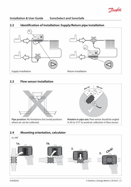
2.2 Identification of installation: Supply/Return pipe installation
Supply installation Return installation
2.3 Flow sensor installation
Pipe position: No limitations but avoid positions where air can be collected.
Rotation in pipe axis: Flow sensor should be angled in 45 to 315° to avoid air collection in flow sensor.
2.4 Mounting orientation, calculator
4 x 90°
Click!
1a.
2.
3.
1b.
6 | © Danfoss | Energy Meters | 2016.01 VUIGB202
Installation & User Guide SonoSelect and SonoSafe
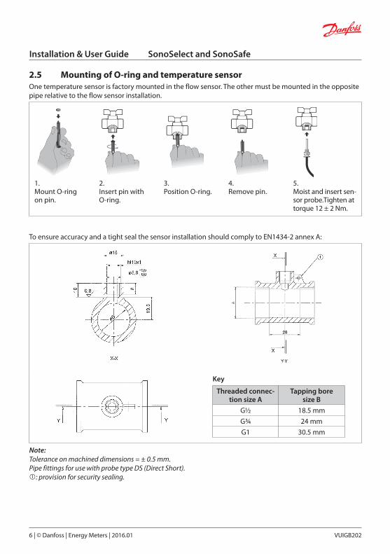
2.5 Mounting of O-ring and temperature sensorOne temperature sensor is factory mounted in the flow sensor. The other must be mounted in the opposite pipe relative to the flow sensor installation.
1.Mount O-ring on pin.
2.Insert pin with O-ring.
3.Position O-ring.
4.Remove pin.
5.Moist and insert sen-sor probe.Tighten at torque 12 ± 2 Nm.
To ensure accuracy and a tight seal the sensor installation should comply to EN1434-2 annex A:
Key
Threaded connec-tion size A
Tapping boresize B
G½ 18.5 mm
G¾ 24 mm
G1 30.5 mm
Note:Tolerance on machined dimensions = ± 0.5 mm.Pipe fittings for use with probe type DS (Direct Short).: provision for security sealing.

VUIGB202 © Danfoss | Energy Meters | 2016.01 | 7
Installation & User Guide SonoSelect and SonoSafe
2.6 Communication (Expansion modules)GeneralBaud rate supported: 2400, 4800, 9600 (auto baud detect). Primary and secondary addressing supported. Primary address: sssssvvNNyyww Secondary address: sssssvvNNyyww
Modules and terminal overview
Wired M-BUS + 2 x pulse input Application and data link layer according to EN13757-3
Wireless OMS + 2 x pulse input Application and data link layer according to EN13757-4 and OMS with 868.95 MHz
Wired RS-485 + 2 x pulse input RS-485 Physical layer Modbus or M-Bus protocol supported
Terminals and cables
Communication Name Terminal No.
M-BusMeter bus (blue or orange) 24
Meter bus (blue or orange) 25
Pulse input
Remote pulse input 1 50
GND 51
Remote pulse input 2 52
GND 53
RS-485
+12V supply (Green and white) 61
RS485 Modbus interface (Blue and white) 62
RS485 Modbus interface (Blue) 63
GND (Green) 64
Cable specification
Pulse input cables <10 m
To ensure IP protection class connecting cable outer jackets must be
Ø4.2 ± 0.1 mm
Communication cables delivered with heat meter.Cable ends are stripped with crimped ferule.
1.0 m
8 | © Danfoss | Energy Meters | 2016.01 VUIGB202
Installation & User Guide SonoSelect and SonoSafe
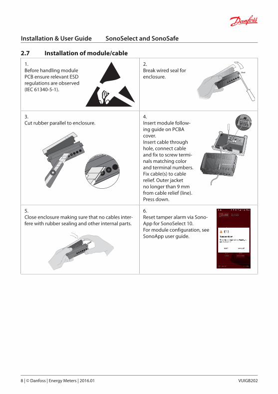
2.7 Installation of module/cable
1.Before handling module PCB ensure relevant ESD regulations are observed (IEC 61340-5-1).
2.Break wired seal for enclosure.
3.Cut rubber parallel to enclosure.
4. Insert module follow-ing guide on PCBA cover.Insert cable through hole, connect cable and fix to screw termi-nals matching color and terminal numbers.Fix cable(s) to cable relief. Outer jacket no longer than 9 mm from cable relief (line). Press down.
5.Close enclosure making sure that no cables inter-fere with rubber sealing and other internal parts.
Click!
6.Reset tamper alarm via Sono-App for SonoSelect 10.For module configuration, see SonoApp user guide.

VUIGB202 © Danfoss | Energy Meters | 2016.01 | 9
Installation & User Guide SonoSelect and SonoSafe
2.8 Battery
1.Before handling module PCB ensure relevant ESD regu-lations are observed (IEC 61340-5-1).
2.Break installation seal and open en-closure.
3.Disconnect battery connector and remove battery.
4. Short circuit battery connectors on PCB using a small flat head screwdriver.
5.Connect new battery to PCB.
6.Fit battery in enclosure.
7.Close enclosure making sure that no cables interfere with rubber sealing or other internal parts.
8.Confirm battery change by pressing the button 2 times within 120 seconds.Reset tamper alarm (E13) via SonoApp for SonoSelect 10.

10 | © Danfoss | Energy Meters | 2016.01 VUIGB202
Installation & User Guide SonoSelect and SonoSafe
3. Commissioning
3.1 Bleeding1. Bleed the system until the flow rate display is steady.2. Make sure no error codes are displayed.3. Check the display for a plausible indication of flow rate and temperatures.4. For SonoSelect: Run installation check using Bluetooth dongle 014U1963 and SonoApp service tool.
3.2 Supply/return configurationOnly available for SonoSelect: Use Bluetooth dongle 014U1963 and SonoApp service tool/Configuration
3.3 Meter sealing
�
�
�
� Tamper monitor/
access level 1 Test seal
(verification mode) Factory seal
3.4 IP class
Calculator IP65 (SonoSelect) / IP54 (SonoSafe)
Flow sensor IP65
Temperature sensor IP65
Note: The IP class can be compromised if cables are subjected to angled tension.

VUIGB202 © Danfoss | Energy Meters | 2016.01 | 11
Installation & User Guide SonoSelect and SonoSafe
4. Function overview
4.1 Menu structure
HoursAlarm Energy Volume
LOOP 1
Supply temp. Display test/All onPower Flow
LOOP 2
Accounting date Monthly date 1 >> Monthly date 12
LOOP 3
Accumulated
Current
History log
2 sec.
5 sec.
click
click
click
Return temp.
2 sec.

12 | © Danfoss | Energy Meters | 2016.01 VUIGB202
Installation & User Guide SonoSelect and SonoSafe
4.2 Display explanation
Working symbol Supply/return mounted installation
Accumulated energy Alarm
Accumulated flow Service/maintenance
Total hours Battery full or low
Instant power Wired communication
Instant flow Wireless communication
Supply temperature Pulse
Return temperature Decimal emphasizer
Temperature difference Units field
4.3 AlarmsE01 System error E09 Low transducer signal
E02 PCB error E10 Transducer error
E03 Battery empty (less than 1 month) E11 Outside measured range
E04 Battery low voltage E12 Negative flow
E05 Battery low (less than 12 months) E13 Tamper alarm
E06 Supply Temperature Error E14 High flow > qss
E07 Return Temperature Error E15 Battery consumption too high
E08Absolute/Difference temperature outside accumulated range
E16 Display overflow (energy/volume)

VUIGB202 © Danfoss | Energy Meters | 2016.01 | 13
Installation & User Guide SonoSelect and SonoSafe
5. Device overview
1
2
3
4
5
6
7
8
9
10
11
12
13
1. Display2. PCBA3. Cover part (PC)4. Battery (Lithium)5. Enclosure connection (PC)6. Transducer (PZT/stainless steel/
PEI)7. Spool piece (Brass)8. Liner fixture (PPS/PEI/stainless
steel)9. Liner (PPS)10. Top part (PC, TPE)11. Module (PCB)12. Bottom part (PC)13. Temperature sensor
6. Disposal
Item Material Disposal
BatteryAA-cell Lithium/thionyl chloride 620 mg Lithium
Approved deposit for lithium batteries
PCBA with displayCoppered epoxy laminate components soldered on, PC, TPE
Electronic waste
Cables Copper with PUR or PVC jackets Cable recovery
Flow sensor(including transducer and liner)
Brass, stainless steel, PPS Metal recovery
Transducer PZT, stainless steel, PEIApproved deposit for PZT
Other plastic parts PC, PPS, PEI, TPE Plastic recovery

14 | © Danfoss | Energy Meters | 2016.01 VUIGB202
Installation & User Guide SonoSelect and SonoSafe

VUIGB202 © Danfoss | Energy Meters | 2016.01 | 15
Installation & User Guide SonoSelect and SonoSafe

16 | © Danfoss | Energy Meters | 2016.01 VUIGB202
Danfoss A/SEnergy Meters • Ulvehavevej 61 • DK-7100 Vejle • DenmarkPhone: +45 7488 8500 • Fax: +45 7488 [email protected] • www.heating.danfoss.com
Danfoss can accept no responsibility for possible errors in catalogues, brochures and other printed material. Danfoss reserves the right to alter its products without notice. This also applies to products already on order provided that such alterations can be made without subsequential changes being necessary in specifications already agreed.All trademarks in this material are property of the respective companies. Danfoss and the Danfoss logotype are trademarks of Danfoss A/S.All rights reserved.


