25
RESCUE EcoTech ® Motor Installation Guide NIDEC MOTOR CORPORATION ®

RESCUE EcoTech® MotorInstallation Guide
NIDEC MOTOR CORPORATION
®

RES
CU
E Ec
oTe
ch®
Mot
or
For Technical Assistance or QuestionsRelated to Your RESCUE EcoTech® Motor,Call the RESCUE EcoTech Motor Hotline:
1-888-540-5540
2

RESC
UE Eco
Tech®
Moto
r
Table of Contents
About the RESCUE EcoTech® Motor............................................4
General Information...................................................................6
Safety Requirements..................................................................7
Motor Installation.......................................................................8
Motor Operation........................................................................13
Continuous Fan Options.............................................................15
Electrical Information.................................................................20
Final Checks...............................................................................21
Troubleshooting.........................................................................22
Maintenance...............................................................................23
Warranty Information.................................................................24
3
RES
CU
E Ec
oTe
ch®
Mot
or
About the RESCUE EcoTech® Motor
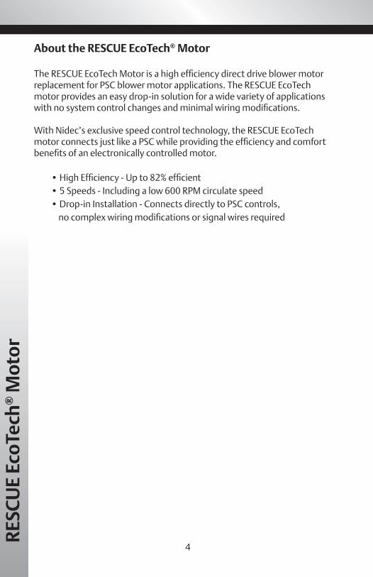
The RESCUE EcoTech Motor is a high efficiency direct drive blower motor replacement for PSC blower motor applications. The RESCUE EcoTechmotor provides an easy drop-in solution for a wide variety of applicationswith no system control changes and minimal wiring modifications.
With Nidec’s exclusive speed control technology, the RESCUE EcoTech motor connects just like a PSC while providing the efficiency and comfort benefits of an electronically controlled motor.
• High Efficiency - Up to 82% efficient• 5 Speeds - Including a low 600 RPM circulate speed• Drop-in Installation - Connects directly to PSC controls, no complex wiring modifications or signal wires required
4

RESC
UE Eco
Tech®
Moto
r
Features:
5
� 82% efficient ECM design � Easy installation to control board � Easy to use voltage change device � Reversible rotation � No capacitor required � Class B insulation � 40° C ambient rated � Electronically protected motor � 36” Leads � Belly-band mounting � Ball bearings

RES
CU
E Ec
oTe
ch®
Mot
or
General InformationEnclosed Materials
� RESCUE EcoTech® Motor � 5 Speed Connector and Harness � Reversing Connector and Harness � “Y” - Harness Adapter � RESCUE EcoTech® Motor Installation Guide � RESCUE EcoTech® Motor System Label � 115V voltage change plug
Initial Inspection
� The shaft should turn freely by hand. � Check the nameplate to verify that data conforms to specifications
of motor ordered.
Storage � Motor should be stored indoors in a clean, dry location. � Proper selection, installation and maintenance will assure long life
and dependable service.
WARNINGUse only specially designed motors where explosive atmospheric hazards exist. See the National Electric Code (NEC), Article 500, or check with local codes agency for explanation of hazardous or classified atmospheres and locations. Unless the motor is specifically marked “ELECTRIC MOTOR FOR HAZARDOUS LOCATIONS”, it is not suitable for use in Class I or II hazardous locations as defined by the NEC.
NOTICEUse motors only in the applications that they are designed for.• The RESCUE EcoTech motor is designed for direct-drive centrifugal blower applications only.
• The RESCUE EcoTech motor is designated for continous, air-over duty, as such, the motor must be mounted in the air stream of an air moving device, such as a fan. DO NOT operate the RESCUE EcoTech motor outside of the air stream as that may overheat and damage the motor.
• Temperature around the motor should not exceed 104° F (40° C), or be less than -20° F (-29° C)
6
Safety Requirements
RESC
UE Eco
Tech®
Moto
r
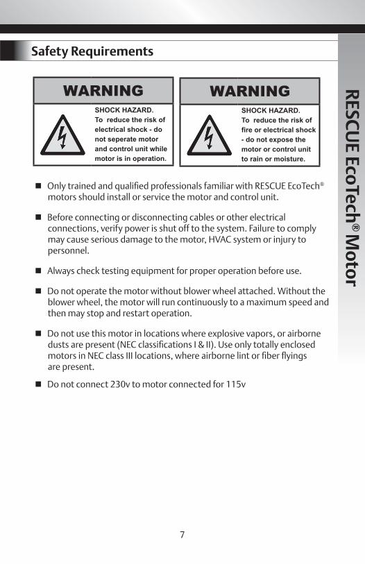
WARNINGSHOCK HAZARD.To reduce the risk ofelectrical shock - donot seperate motorand control unit whilemotor is in operation.
WARNINGSHOCK HAZARD.To reduce the risk offire or electrical shock - do not expose themotor or control unit to rain or moisture.
� Only trained and qualified professionals familiar with RESCUE EcoTech® motors should install or service the motor and control unit.
� Before connecting or disconnecting cables or other electrical connections, verify power is shut off to the system. Failure to comply may cause serious damage to the motor, HVAC system or injury to personnel.
� Always check testing equipment for proper operation before use.
� Do not operate the motor without blower wheel attached. Without the blower wheel, the motor will run continuously to a maximum speed and then may stop and restart operation.
� Do not use this motor in locations where explosive vapors, or airborne dusts are present (NEC classifications I & II). Use only totally enclosed motors in NEC class III locations, where airborne lint or fiber flyings are present.
� Do not connect 230v to motor connected for 115v
7

RES
CU
E Ec
oTe
ch®
Mot
or
Motor Installation
WARNING• These instructions provide field technicians a guide for installing a RESCUE EcoTech® motor and are intended for a typical air handler/ furnace equipment system. It does not override or replace instructions suggested by the manufacturer of the HVAC system.
• All aspects of the installation must conform to the requirements of the NEC, including Article 430 (Motor Circuits and Controllers), and all local codes.
• It is good practice to label all wires and connectors prior to disconnection. Wiring errors can cause significant damage to equipment or serious injury or death. Verify proper operation after servicing.
To prevent electric shock, personal injury, or death, turn off the electric power at the disconnect or the main service panel before making any electrical connections.
Removing the PSC Motor1. Disconnect the main power to the HVAC system.2. Label wires and connectors between the motor and equipment control board. Also note existing PSC equipment system settings:
• Motor lead connections to system control board• Equipment system voltage (115V or 230V)• Blower motor hp (nameplate)• Motor amp rating (nameplate)• Blower wheel rotation direction (nameplate) • Motor mounting configuration
3. Disconnect the existing motor wiring harness from the control board.4. Remove the blower assembly from the HVAC equipment. Refer to the manufacturer’s installation manual for blower removal instructions.5. Remove the mounting bracket, old motor, and capacitor (if applicable) from the blower assembly.
8

RESC
UE Eco
Tech®
Moto
r
NOTICEMotor must be securely fastened to minimize noise and prevent vibration. For secure mounting use high-quality bolts of the largest possible diameter.
Installing the RESCUE EcoTech® Motor
CAUTIONDo not strike the motor shaft with hammer or other tool. This may cause serious damage to the bearings.
Important: Verify the RESCUE EcoTech motor is of an equivalenthorsepower and voltage rating as that of the prior PSC motor.
1. Install the RESCUE EcoTech motor using a belly-band style mounting bracket. If the RESCUE EcoTech motor is replacing a motor mounted by flex (torsion) mounting or hub ring mounting, a Kit #44 Flex Mounting Kit will allow easy installation of the RESCUE EcoTech Motor in most applications. If the OEM Blower Motor is mounted with:
Important: To minimize the chance of moisture entering the motor through the connector, the motor should be installed with thewire harness exit as shown in Figure 1.
or Use
Flex (Torsion) MountedPSC Motor
Hub Ring Mounted PSC Motor
Catalog #44Flex Mount Kit
Figure 1
9

RES
CU
E Ec
oTe
ch®
Mot
or
10
2. Set the voltage on the Rescue EcoTech® motor to match that of the replaced PSC motor. The motor is shipped connected for 208-230v systems. If 115v is required, disconnect power to the motor and locate the voltage change device as shown below. Open the “door” marked “230V” by unlatching the right side and remove the door. Locate the 115V plug in the accessory bag. Insert 115V plug into the mating connector.

RESC
UE Eco
Tech®
Moto
r
3. Position the blower wheel on the motor shaft so it is properly centered in the blower housing and tighten the blower wheel set screw.
4. Connect the 5 speed and reversing harness to the motor connector as shown in Figure 2. See Page 14 for the positioning of the reversing connector to specify rotation.5. Connect the ground wire (green lead) to the metal blower housing using a sheet metal screw.6. Install the blower assembly back into the HVAC equipment.7. Connect the supplied wiring harness to the system control. Use motor lead connections comparable to the existing PSC lead connections as outlined in the Connecting the RESCUE EcoTech® Motor section (page 12).8. Verify airflow meets OEM equipment specifications in all modes of operation.9. Place the RESCUE EcoTech motor decal (Figure 3) on the outside of the furnace or air handler, noting date of installation and providin relevant contact information.
Figure 2
Figure 3
The RESCUE EcoTech® motor is an electronicallycotrolled, high efficiency blower motor that connectsdirectly to standard PSC controls featuring:
It is normal, upon energizing a speed tap, for the motor to experience a 2 to 3 second delay before beginning operation and take 10 to 15 seconds before reaching full speed
For Questions or Concerns visit:www.emersonclimate.com/RescueEcotech
orCall our RESCUE EcoTech Hotline:
1-888-540-5540
This unit upgraded with a
High EfficiencyBlower Motor
Installed as HP: _______________________
Installed Voltage: ______________________
Date of Installation: ____________________
11

RES
CU
E Ec
oTe
ch®
Mot
or
Connecting RESCUE EcoTech® Motor
Connect the leads from the RESCUE EcoTech® motor to the system control board using the wiring diagram below (Figure 4). Connect the speed taps using similar speeds as noted when removing the PSC blower motor.
For various methods of connecting the RESCUE EcoTech motor’s lowcirculation speed, see Continuous Fan Options section (page15). If further adjustment of the motor speed is required after checking the airflow, refer to the Adjusting Speed Settings section (page 14).
Note: Lead colors on PSC motors can vary depending on system and motor manufacturer. Refer to OEM motor label or system documentation todetermine the original speed connections.
Figure 4
For typical applications, select the EcoTech motor and HP replacement you want to install.Select the suggested speed taps from the wire harness for your cooling and heating speeds.For constant fan / circulation, use the low (red) speed tap.For techincal assistance, call the Rescue EcoTech help line at 888-540-5540
12
Rescue EcoTech#
Rescue Motor HP
Cooling Heating Cont Fan
5552ET 1 HP High Med-Hi Low
3/4 HP Med-Hi Med Low
1/2 HP Med Med-Low Low
5542ET 3/4 HP High Med-Hi Low
1/2 HP Med-HI Med Low
1/3 HP Med Med-Low Low
5532ET 1/2 HP High Med-Hi Low
1/3 HP Med-HI Med Low
1/4 HP Med Med-Low Low
5522ET 1/3 HP High Med-Hi Low
1/4 HP Med-Hi Med Low
1/5 HP Med Med-Low Low
SOLID LINES ARE SHOWN FOR CCWLEROTATION. FOR CWLE ROTATION,CHANGE CONNECTOR ORIENTATION TODASHED LINE.
WHITE - NEUTRAL (CWLE)
GREEN - GROUND
WHITE - NEUTRAL (CCWLE)
BLACK - HIGH
YELLOW - MEDIUM HIGH
BLUE - MEDIUM
ORANGE - MEDIUM LOW
RED - LOW
LINE

Motor Operation
Starting the Motor
Once installed, briefly test motor operation in all system modes. Check for unusual noises and vibration (see troubleshooting, page 22).
It is normal, upon energizing a speed tap, for the motor to experience a 2 to 3 second delay before beginning operation and take 10 to 15 seconds before reaching full speed.
Check motor amperage. Amp reading at the highest speed setting should be within 10% of the specification shown on the nameplate.
Operating the Motor
A motor should not be operated under conditions that cause the motorprotection to continually operate. The motor may be overloaded or thesupply voltage or frequency may be incorrect.
Actual operating speed is determined only with the load applied. Ingeneral, if the motor is properly sized and connected to its load, there will be a detectable speed difference when different speed taps are energized.However, when operating the motor without a load, the motor will runcontinuously to a maximum speed and then may stop and restart operation.
WARNING
Electric Shock Hazard! Motor must be properly grounded.
NOTICEFor air moving applications, all enclosure covers and panels must be in place before measuring the amperage.
WARNING
Be careful when touching the exterior of an operating motor! Motor may be hot enough to cause serious injury. This condition is normal for most motors when operated at rated load and voltage.
13
RESC
UE Eco
Tech® M
otor

RES
CU
E Ec
oTe
ch®
Mot
or
Checking OperationVerify that the correct airflow is present in all operating modes. Verify that temperature rise measurements in all operating modes conform to the specifications provide by the original equipment manufacturer. If not, refer to Adjusting Speed Settings section.
If the motor operates at high speed with very little or no airflow, motor may be rotating the wrong direction. Disconnect power to the furnace or air handler then flip the motor direction connector. (Figure 5)
Adjusting Speed SettingsThe motor lead connections should be comparable to the existing PSC motor lead connections. If an adjustment is needed to meet the airflow needs outlined by the system OEM, adjust the leads connected untilcorrect airflow is met.
If the motor operates at the same speed on the lower speed connections as on the highest speed, the motor may be under loaded and therefore reaching the maximum speed limit. Continue choosing a lower speed lead to obtain the correct airflow for each particular operating mode. Many OEM motors are stronger than the HP label indicates. An usual combination of the amp draw and capacitor size can be an indicator of this.
Measuring Temperature RiseTemperature rise is a calculated difference between the temperatures in the supply air outlet and the return air inlet of the HVAC system. The tempera-ture reading should be taken inside of the return air and supply air ducts, as close to the HVAC system as possible. If there is no access to the ductwork, then take the measurement in a return and supply grill, closest to the HVAC system. Refer to the furnace/air handler manufacturer’s rating plate for temperature rise specifications.
Counter Clockwise Rotation Clockwise RotationFigure 5
Note: Wire leads omited for clarity.
14

CAUTION
To prevent damage to HVAC system verify temperature rise is within OEM specifications in all modes of operation.
Example:A furnace rating plate specifies a temperature rise of 35°F (19° C) to 55°F (31° C) and the actual measured rise is 60°F, the blower speed will need to be increased to reduce the temperature rise.
If the temperature rise is below the lower limit specified on the rating plate, decrease the blower speed to increase the temperature rise.
Continuous Fan OptionsThe RESCUE EcoTech® motor’s low speed connection is designed to operate at approximately 50% of the full load speed, providing efficient continuous fan operation with low noise or draft. System Controls Featuring a Discrete Fan Speed:
Some system control boards provide a connection point (Figure 6) tooperate the fan at a mode other than heat or cool. In these instances,connect the Low speed motor lead (Red) to the appropriate providedconnection point. Fan operation can be controlled by the user fromthe thermostat.
Note: Diagram is for illustration purposes, actual connections and components will vary depending on system type and manufacturer.
Figure 6
15
RESC
UE Eco
Tech® M
otor
RES
CU
E Ec
oTe
ch®
Mot
or
System Controls with No Discrete Fan Setting:
The RESCUE EcoTech® motor allows the low speed connections to be energized at the same time as a higher speed connection, operating at the higher speeds. This feature allows use of the low circulate speed even if the furnace or air handler system control board is not equipped with a dedicated fan mode connection point.
The following are three different methods of operating the motor incontinuous fan mode without a fan mode connection point on thesystem control board. A special “Y”-harness adapter has been supplied with the RESCUE EcoTech® motor to facilitate connection of the lowest speed setting. All three options below utilize this “Y”-harness adapterto provide the low circulation speed in systems when no dedicatedcontinuous fan speed connection is available.
NOTICE
Connect only the Low speed motor lead to the Red lead of the “Y”- har-ness adapter. Do not connect any of the higher speed motor leads to the harness. Do not connect the Red lead of the “Y”-harness adapter in line with the system power supply. Doing this may result in permanent damage to the “Y”-harness adapter itself.
See the following pages for example ofwiring in the motor this way.
16

RESC
UE Eco
Tech®
Moto
r
Note:Using the supplied “Y”-harness adapter, connect the Low speed (Red) motor lead in parallel to the lead supplying the power to the system control (Figure 7).
The black leg of the “Y”-harness adapter should be connected in line with the power supply to the control board. The Red lead of the harness should be connected to the Low speed (Red) lead from the motor.
� Safety protection SHOULD NOT be disabled in this configuration, .e., door interlock switch.
� In this configuration the blower motor will operate continuously at low speed any time the power is supplied to the system, until a higher speed connection is energized.
Option 1: Connecting directly to the system power supply:
Figure 7
17

RES
CU
E Ec
oTe
ch®
Mot
or
Diagram is for illustration purposes, actual connections andcomponents will vary depending on system type and manufacturer.
Using the supplied “Y”-harness adapter, connect the Low speed (Red) motor lead in parallel to the lead supplying the power to the system control (Figure 8).
The black leg of the “Y”-harness adapter should be connected in line with the power supply to the control board. The Red lead of the harness shouldbe connected to the Low speed (Red) lead from the motor with a switch mounted in series with the Low speed lead.
� Safety protection SHOULD NOT be disabled in this configuration, i.e., door interlock switch.
� Switch should be a 15Amp, UL rated device mounted to the equipment system housing.
� In this configuration, the continuous fan operation may be enabled/ disapble by the user at the external switch. When enabled, te blower motor will operate continuously at low speed any time power is supplied to the system, until a higher speed connection is energized. The fan switch should remain on “Auto”.
Option 2: Installing an external switch in series with low speed motor lead:
Figure 8
18
Note:

RESC
UE Eco
Tech®
Moto
r
Note: Diagram is for illustration purposes, actual connections andcomponents will vary depending on system type and manufacturer.
Using the supplied “Y”-harness adapter, connect power to system control board and relay. Connect the Low speed motor lead to the relay (Figure 9).
The black leg of the “Y”-harness adapter should be connected in line with the power supply to the control board. The Red lead of the harness shouldbe connected to the relay.
� Safety protection SHOULD NOT be disabled in this configuration, i.e.,door interlock switch.
� The green 24V wire should remain disconnected from the system control board
� In this configuration the continuous fan option is enabled/disabled at the thermostat. You can switch the fan on or auto ad desired or program the fan to be on for different modes and times as the programmable thermostat is configured.
Option 3: Install a 24V relay connected to the G wire of the thermostat:
Figure 9
19

RES
CU
E Ec
oTe
ch®
Mot
or
Electrical Information
NOTICE
•Voltage, frequency, and the number of power supply phases must correspond to that shown on the motor nameplate. If the number of phases is not shown on the nameplate, the motor is single phase. Voltages that are too low can reduce the performance of the motor.
• Insulate all connections carefully to prevent grounding or short circuits. Reinstall all conduit and terminal box covers. Do not force connections into the conduit box.
• Multi-Speed Fan Motors may have leads that will not be used. Exposed terminals or copper wire of these unused lead ends must be individually insulated. In addition, their bare wire ends must not be connected to either of the leads where voltage will be applied.
• Any switching device used to control a motor must have a horsepower rating equal to or greater than the motor.
• An electronic adjustable speed control must not be used with the RESCUE EcoTech motor.
CAUTION
• Motor must be securely and adequately grounded by wiring with a grounded metallic conduit, or other grounding method approved by the NEC and local codes.
• Voltage and moving parts around motors and motor driven equipment can cause serious or fatal injuries. Turn off power before connecting or servicing the motor.
20

Final Checks
� Check mounting and fastening of motor and control unit. Make sure control unit and motor are securely attached together and mounted tightly in HVAC system.
� Check control unit connectors. Inspect for shorts, detached wiring, or loose connections.
� Check all wiring harness connections. Make sure they are securely connected to control unit connectors.
� Check blower motor and verify wheel rotation. Make sure it spins freely manually without effort or assisted means in both directions. Verify set screw on blower wheel has been properly tightened.
� Check that all leads have been properly connected to the control board and any unconnected leads are properly insulated and secured.
� Check circuit breaker.
21
RESC
UE Eco
Tech® M
otor
RES
CU
E Ec
oTe
ch®
Mot
or
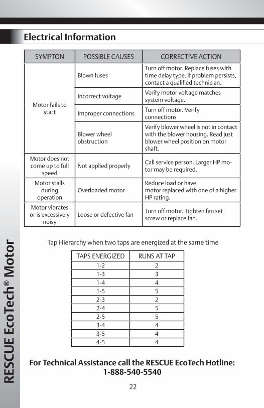
SYMPTON POSSIBLE CAUSES CORRECTIVE ACTION
Motor fails to start
Blown fusesTurn off motor. Replace fuses with time delay type. If problem persists, contact a qualified technician.
Incorrect voltageVerify motor voltage matches system voltage.
Improper connectionsTurn off motor. Verify connections
Blower wheel obstruction
Verify blower wheel is not in contact with the blower housing. Read just blower wheel position on motor shaft.
Motor does not come up to full
speed Not applied properly
Call service person. Larger HP mo-tor may be required.
Motor stalls during
operationOverloaded motor
Reduce load or have motor replaced with one of a higher HP rating.
Motor vibrates or is excessively
noisyLoose or defective fan
Turn off motor. Tighten fan set screw or replace fan.
For Technical Assistance call the RESCUE EcoTech Hotline:1-888-540-5540
Electrical Information
22
TAPS ENERGIZED RUNS AT TAP1-2 21-3 31-4 41-5 52-3 22-4 52-5 53-4 43-5 44-5 4
Tap Hierarchy when two taps are energized at the same time

WARNING
Before performing any maintenance, disconnect power and allow motor to come to a complete stop. This will allow the capacitors to discharge any residual voltage, if any for safety.
Maintenance
� Periodically inspect the installation. Check for dirt accumulations, unusual noises or vibration, overheating, worn or loose couplings, high motor amps, poor wiring or overheated connections, loose mounting bolts or guards, and worn motor starter contacts.Check control unit connectors. Inspect for shorts, detached wiring, or loose connections.
� Remove dirt accumulation, particularly in and around vent openings, by vacuuming. Dirt accumulations can cause motor overheating and a fire hazard.
� Do not use solvents! Some solvents may attack motor insulation, finish or bearing lubricants. Solvents are highly flammable.
� Ball bearing motors are permanently lubricated. No maintenance is required.
23
RESC
UE Eco
Tech® M
otor

RES
CU
E Ec
oTe
ch®
Mot
or
Warranty InformationLIMITED WARRANTYNidec Motor Corporation (“Nidec”). extends the following LIMITED WARRANTY to the purchaser and to its customers (collectively referred to as the “Purchaser”) of the enclosed motor and com-ponents: the motor and components are free from defects in materials and workmanship under normal use, service and maintenance FOR A PERIOD OF 24 MONTHS FROM THE DATE OF ORIGI-NAL PURCHASE FROM NIDEC OR THE NIDEC DEALER/RETAILER, NOT TO EXCEED 30 MONTHS FROM THE DATE OF MANUFACTURE BY NIDEC. THE FOREGOING WARRANTY IS THE ONLYWARRANTY GIVEN AND NO OTHER WARRANTY IS PROVIDED, EXPRESS OR IMPLIED, INCLUD-ING WITHOUT LIMITATION, MERCHANTABILITY OR FITNESS FOR A PARTICULAR PURPOSE. Certain aspects of disclaimers are not applicable to consumer products, i.e., motors and com-ponents acquired by individuals and used for personal, family or household purposes (as dis-tinguished from industrial or other purposes). Some states do not allow limitations on how long an implied warranty lasts, so the above limitation may not apply to you. This warranty gives you specific legal rights, and you may have other rights which vary from state to state.
Certain repairs or services are the responsibility of the Purchaser and the Purchaser is expected to pay for them. This warranty does not extend to any losses or damages due to misuse, ac-cident, abuse, neglect, negligence, unauthorized modification or alteration, use beyond rated capacity, or improper installation, maintenance, application or use, including, without limitation, use in a manner contrary to the accompanying instructions or applicable codes.
If within thirty (30) days after Purchaser’s discovery of any warranty defects within the above stated warranty period, Purchaser notifies Nidec or the dealer from whom the motor was pur-chased in writing, Nidec shall, at its option and as Purchaser’s exclusive remedy, repair or replace or refund the purchase price for, that portion of the motor and components found by Nidec to be defective. Failure by Purchaser to give such written notice within the applicable time period shall be deemed an absolute and unconditional waiver of Purchaser’s claim for such defects. Purchas-er must write or call the dealer from whom the motor was purchased for directions regarding the shipment of the motor, with freight prepaid by the Purchaser, to an authorized service location for warranty service. If Purchaser is unable to contact the dealer to obtain sufficient instructions re-garding the handling of the motor, Purchaser should write Nidec at the address below, giving the motor model number, the dealer’s name, address and number of dealer’s invoice; and describing the nature of the alleged defect. Arrangements for warranty service will then be made by Nidec. If the motor is damaged in transit, Purchaser should file a claim directly with the carrier. IN NO EVENT, REGARDLESS OF THE FORM OF THE CLAIM OR CAUSE OFACTION (WHETHER BASED IN CONTRACT, INFRINGEMENT, NEGLIGENCE, STRICTLIABILITY, OTHER TORT OR OTHERWISE), SHALL NIDEC’S LIABILITY TO PURCHASER OR ITS CUSTOMER EXCEED THE PRICE PAID BY PURCHASER FOR THE SPECIFIC MOTOR OROTHER GOODS PROVIDED BY GIVING RISE TO THE CAUSE OF ACTION. IN NO EVENT SHALL NI-DEC’S LIABILITY TO PURCHASER OR ITS CUSTOMER EXTEND TO INCLUDE INCIDENTAL CONSEQUENTIAL OR PUNITIVE DAMAGES. WITH RESPECT TOCONSUMER PRODUCTS, SOME STATES DO NOT ALLOW THE EXCLUSION ORLIMITATION OF INCIDENTAL OR CONSEQUENTIAL DAMAGES, SO THE ABOVE LIMITATION OREXCLUSION MAY NOT APPLY TO YOU.
24

All marks shown within this document are propertiesof their respective owners. © 2011Nidec Motor Corporation.All rights reserved. Printed in the USA.Trademarks followed by the ® symbol areregistered with the U.S. Patent and Trademark Office.
B71795167NIDEC MOTOR CORPORATION


