72
Installer and user reference guide VRV IV-S system air conditioner English Installer and user reference guide VRV IV-S system air conditioner RXYSQ8TMY1B RXYSQ10TMY1B RXYSQ12TMY1B
Installer and user reference guideVRV IV-S system air conditioner English
Installer and userreference guide
VRV IV-S system air conditioner
RXYSQ8TMY1B RXYSQ10TMY1B RXYSQ12TMY1B
Table of Contents
Installer and user reference guide
2RXYSQ8~12TMY1B
VRV IV-S system air conditioner4P404225-1 – 2015.03
Table of Contents
1 General safety precautions 31.1 About the documentation .......................................................... 3
1.1.1 Meaning of warnings and symbols.............................. 31.2 For the user ............................................................................... 41.3 For the installer.......................................................................... 4
1.3.1 General ....................................................................... 41.3.2 Installation site ............................................................ 41.3.3 Refrigerant .................................................................. 51.3.4 Brine............................................................................ 51.3.5 Water .......................................................................... 51.3.6 Electrical ..................................................................... 6
2 About the documentation 62.1 About this document.................................................................. 6
For the installer 7
3 About the box 73.1 Overview: About the box ........................................................... 73.2 Outdoor unit............................................................................... 7
3.2.1 To unpack the outdoor unit ......................................... 73.2.2 To handle the outdoor unit .......................................... 73.2.3 To remove the accessories from the outdoor unit....... 83.2.4 To remove the transportation stay .............................. 8
4 About the units and options 84.1 Overview: About the units and options...................................... 84.2 Identification .............................................................................. 8
4.2.1 Identification label: Outdoor unit ................................. 84.3 About the outdoor unit ............................................................... 94.4 System layout............................................................................ 94.5 Combining units and options ..................................................... 9
4.5.1 About combining units and options ............................. 94.5.2 Possible combinations of indoor units......................... 94.5.3 Possible options for the outdoor unit........................... 9
5 Preparation 95.1 Overview: Preparation............................................................... 95.2 Preparing installation site .......................................................... 9
5.2.1 Installation site requirements of the outdoor unit ........ 105.2.2 Additional installation site requirements of the
outdoor unit in cold climates ....................................... 115.2.3 Securing safety against refrigerant leaks.................... 11
5.3 Preparing refrigerant piping....................................................... 125.3.1 Refrigerant piping requirements.................................. 125.3.2 Refrigerant piping material.......................................... 125.3.3 To select the piping size ............................................. 135.3.4 To select refrigerant branch kits.................................. 145.3.5 Refrigerant piping length and height difference .......... 14
5.4 Preparing electrical wiring ......................................................... 155.4.1 About electrical compliance ........................................ 155.4.2 Safety device requirements ........................................ 15
6 Installation 166.1 Overview: Installation ................................................................ 166.2 Opening the units ...................................................................... 16
6.2.1 About opening the units .............................................. 166.2.2 To open the outdoor unit............................................. 16
6.3 Mounting the outdoor unit.......................................................... 166.3.1 About mounting the outdoor unit................................. 166.3.2 Precautions when mounting the outdoor unit.............. 166.3.3 To provide the installation structure ............................ 166.3.4 To install the outdoor unit............................................ 176.3.5 To provide drainage .................................................... 176.3.6 To prevent the outdoor unit from falling over .............. 17
6.4 Connecting the refrigerant piping ............................................... 186.4.1 About connecting the refrigerant piping ....................... 186.4.2 Precautions when connecting the refrigerant piping .... 186.4.3 Pipe bending guidelines............................................... 186.4.4 To braze the pipe end .................................................. 186.4.5 Using the stop valve and service port .......................... 186.4.6 To remove the pinched pipes....................................... 196.4.7 To connect the refrigerant piping to the outdoor unit ... 206.4.8 To connect the refrigerant branching kit ...................... 21
6.5 Checking the refrigerant piping .................................................. 216.5.1 About checking the refrigerant piping .......................... 216.5.2 Checking refrigerant piping: General guidelines .......... 226.5.3 Checking refrigerant piping: Setup............................... 226.5.4 To perform a leak test .................................................. 226.5.5 To perform vacuum drying ........................................... 22
6.6 To insulate the refrigerant piping................................................ 226.7 Charging refrigerant ................................................................... 23
6.7.1 About charging refrigerant ........................................... 236.7.2 Precautions when charging refrigerant ........................ 236.7.3 To determine the additional refrigerant amount ........... 236.7.4 To charge refrigerant ................................................... 246.7.5 Error codes when charging refrigerant......................... 256.7.6 To fix the fluorinated greenhouse gases label ............. 25
6.8 Connecting the electrical wiring.................................................. 256.8.1 About connecting the electrical wiring.......................... 256.8.2 Precautions when connecting electrical wiring ............ 266.8.3 Guidelines when knocking out knockout holes ............ 276.8.4 Guidelines when connecting the electrical wiring ........ 276.8.5 To connect the electrical wiring on the outdoor unit..... 27
6.9 Finishing the outdoor unit installation ......................................... 286.9.1 To finish the transmission wiring.................................. 286.9.2 To close the outdoor unit ............................................. 29
7 Configuration 297.1 Overview: Configuration ............................................................. 297.2 Making field settings................................................................... 29
7.2.1 About making field settings .......................................... 297.2.2 To access the field setting components....................... 297.2.3 Field setting components ............................................. 297.2.4 To access mode 1 or 2 ................................................ 307.2.5 To use mode 1 ............................................................. 307.2.6 To use mode 2 ............................................................. 317.2.7 Mode 1 (and default situation): Monitoring settings ..... 317.2.8 Mode 2: Field settings.................................................. 337.2.9 To connect the PC configurator to the outdoor unit ..... 36
7.3 Energy saving and optimum operation....................................... 367.3.1 Available main operation methods............................... 367.3.2 Available comfort settings ............................................ 377.3.3 Example: Automatic mode during cooling.................... 387.3.4 Example: Automatic mode during heating ................... 38
8 Commissioning 398.1 Overview: Commissioning.......................................................... 398.2 Precautions when commissioning .............................................. 398.3 Checklist before commissioning................................................. 398.4 Checklist during commissioning ................................................. 40
8.4.1 About test run............................................................... 408.4.2 To perform a test run (7-LEDs display)........................ 408.4.3 To perform a test run (7-segments display) ................. 408.4.4 Correcting after abnormal completion of the test run... 418.4.5 Operating the unit ........................................................ 41
9 Hand-over to the user 41
10 Maintenance and service 4110.1 Overview: Maintenance and service .......................................... 4110.2 Maintenance safety precautions................................................. 41
10.2.1 To prevent electrical hazards....................................... 4110.3 Checklist for yearly maintenance of the outdoor unit ................. 4110.4 About service mode operation.................................................... 42
10.4.1 To use vacuum mode .................................................. 42
1 General safety precautions
Installer and user reference guide
3RXYSQ8~12TMY1BVRV IV-S system air conditioner4P404225-1 – 2015.03
10.4.2 To recover refrigerant ................................................. 42
11 Troubleshooting 4211.1 Overview: Troubleshooting........................................................ 4211.2 Precautions when troubleshooting ............................................ 4211.3 Solving problems based on error codes.................................... 42
11.3.1 Error codes: Overview ................................................ 42
12 Disposal 45
13 Technical data 4613.1 Overview: Technical data .......................................................... 4613.2 Dimensions: Outdoor unit .......................................................... 4613.3 Service space: Outdoor unit ...................................................... 4813.4 Components: Outdoor unit ........................................................ 5013.5 Piping diagram: Outdoor unit..................................................... 5213.6 Wiring diagram: Outdoor unit .................................................... 5413.7 Technical specifications: Outdoor unit....................................... 5813.8 Capacity table: Indoor unit......................................................... 60
For the user 61
14 About the system 6114.1 System layout............................................................................ 61
15 User interface 61
16 Before operation 61
17 Operation 6217.1 Operation range ........................................................................ 6217.2 Operating the system ................................................................ 62
17.2.1 About operating the system ........................................ 6217.2.2 About cooling, heating, fan only, and automatic
operation ..................................................................... 6217.2.3 About the heating operation........................................ 6217.2.4 To operate the system ................................................ 62
17.3 Using the dry program............................................................... 6217.3.1 About the dry program ................................................ 6217.3.2 To use the dry program............................................... 62
17.4 Adjusting the air flow direction................................................... 6317.4.1 About the air flow flap ................................................. 63
17.5 Setting the master user interface .............................................. 6317.5.1 About setting the master user interface ...................... 6317.5.2 To designate the master user interface (VRV DX)...... 6317.5.3 To designate the master user interface (RA DX) ........ 6317.5.4 About control systems................................................. 64
18 Energy saving and optimum operation 6418.1 Available main operation methods ............................................ 6418.2 Available comfort settings ......................................................... 64
19 Maintenance and service 6419.1 Maintenance after a long stop period ........................................ 6519.2 Maintenance before a long stop period ..................................... 6519.3 About the refrigerant.................................................................. 6519.4 After-sales service and warranty ............................................... 65
19.4.1 Warranty period .......................................................... 6519.4.2 Recommended maintenance and inspection.............. 6519.4.3 Recommended maintenance and inspection cycles... 6519.4.4 Shortened maintenance and replacement cycles ....... 66
20 Troubleshooting 6620.1 Error codes: Overview............................................................... 6720.2 Symptoms that are not air conditioner troubles......................... 67
20.2.1 Symptom: The system does not operate .................... 6820.2.2 Symptom: Fan operation is possible, but cooling and
heating do not work..................................................... 6820.2.3 Symptom: The fan strength does not correspond to
the setting ................................................................... 6820.2.4 Symptom: The fan direction does not correspond to
the setting ................................................................... 68
20.2.5 Symptom: White mist comes out of a unit (Indoorunit) .............................................................................. 68
20.2.6 Symptom: White mist comes out of a unit (Indoorunit, outdoor unit) ......................................................... 68
20.2.7 Symptom: The user interface display reads "U4" or"U5" and stops, but then restarts after a few minutes.. 68
20.2.8 Symptom: Noise of air conditioners (Indoor unit)......... 6820.2.9 Symptom: Noise of air conditioners (Indoor unit,
outdoor unit)................................................................. 6820.2.10 Symptom: Noise of air conditioners (Outdoor unit) ...... 6820.2.11 Symptom: Dust comes out of the unit .......................... 6820.2.12 Symptom: The units can give off odours...................... 6820.2.13 Symptom: The outdoor unit fan does not spin ............. 6820.2.14 Symptom: The display shows "88"............................... 6820.2.15 Symptom: The compressor in the outdoor unit does
not stop after a short heating operation ....................... 6920.2.16 Symptom: The inside of an outdoor unit is warm
even when the unit has stopped .................................. 6920.2.17 Symptom: Hot air can be felt when the indoor unit is
stopped ........................................................................ 69
21 Relocation 69
22 Disposal 69
23 Glossary 69
1 General safety precautions
1.1 About the documentation▪ The original documentation is written in English. All other
languages are translations.
▪ The precautions described in this document cover very importanttopics, follow them carefully.
▪ The installation of the system, and all activities described in theinstallation manual and the installer reference guide must beperformed by an authorized installer.
1.1.1 Meaning of warnings and symbols
DANGER
Indicates a situation that results in death or serious injury.
DANGER: RISK OF ELECTROCUTION
Indicates a situation that could result in electrocution.
DANGER: RISK OF BURNING
Indicates a situation that could result in burning because ofextreme hot or cold temperatures.
WARNING
Indicates a situation that could result in death or seriousinjury.
CAUTION
Indicates a situation that could result in minor or moderateinjury.
NOTICE
Indicates a situation that could result in equipment orproperty damage.
INFORMATION
Indicates useful tips or additional information.
1 General safety precautions
Installer and user reference guide
4RXYSQ8~12TMY1B
VRV IV-S system air conditioner4P404225-1 – 2015.03
1.2 For the user▪ If you are not sure how to operate the unit, contact your installer.
▪ This appliance can be used by children aged from 8 years andabove and persons with reduced physical, sensory or mentalcapabilities or lack of experience and knowledge if they have beengiven supervision or instruction concerning use of the appliance ina safe way and understand the hazards involved. Children shallnot play with the appliance. Cleaning and user maintenance shallnot be made by children without supervision.
WARNING
To prevent electric shocks or fire:
▪ Do NOT rinse the unit.
▪ Do NOT operate the unit with wet hands.
▪ Do NOT place any objects containing water on the unit.
NOTICE
▪ Do NOT place any objects or equipment on top of theunit.
▪ Do NOT sit, climb or stand on the unit.
▪ Units are marked with the following symbol:
This means that electrical and electronic products may not bemixed with unsorted household waste. Do NOT try to dismantlethe system yourself: the dismantling of the system, treatment ofthe refrigerant, of oil and of other parts must be done by anauthorized installer and must comply with applicable legislation.Units must be treated at a specialized treatment facility for reuse,recycling and recovery. By ensuring this product is disposed ofcorrectly, you will help to prevent potential negative consequencesfor the environment and human health. For more information,contact your installer or local authority.
▪ Batteries are marked with the following symbol:
This means that the batteries may not be mixed with unsortedhousehold waste. If a chemical symbol is printed beneath thesymbol, this chemical symbol means that the battery contains aheavy metal above a certain concentration.Possible chemical symbols are: Pb: lead (>0.004%).Waste batteries must be treated at a specialized treatment facilityfor reuse. By ensuring waste batteries are disposed of correctly,you will help to prevent potential negative consequences for theenvironment and human health.
1.3 For the installer
1.3.1 GeneralIf you are not sure how to install or operate the unit, contact yourdealer.
NOTICE
Improper installation or attachment of equipment oraccessories could result in electric shock, short-circuit,leaks, fire or other damage to the equipment. Only useaccessories, optional equipment and spare parts made orapproved by Daikin.
WARNING
Make sure installation, testing and applied materialscomply with applicable legislation (on top of theinstructions described in the Daikin documentation).
CAUTION
Wear adequate personal protective equipment (protectivegloves, safety glasses,…) when installing, maintaining orservicing the system.
WARNING
Tear apart and throw away plastic packaging bags so thatnobody, especially children, can play with them. Possiblerisk: suffocation.
DANGER: RISK OF BURNING
▪ Do NOT touch the refrigerant piping, water piping orinternal parts during and immediately after operation. Itcould be too hot or too cold. Give it time to return tonormal temperature. If you must touch it, wearprotective gloves.
▪ Do NOT touch any accidental leaking refrigerant.
WARNING
Provide adequate measures to prevent that the unit can beused as a shelter by small animals. Small animals thatmake contact with electrical parts can cause malfunctions,smoke or fire.
CAUTION
Do NOT touch the air inlet or aluminum fins of the unit.
NOTICE
▪ Do NOT place any objects or equipment on top of theunit.
▪ Do NOT sit, climb or stand on the unit.
NOTICE
Works executed on the outdoor unit are best done underdry weather conditions to avoid water ingress.
In accordance with the applicable legislation, it might be necessaryto provide a logbook with the product containing at least: informationon maintenance, repair work, results of tests, stand-by periods,…
Also, at least, following information must be provided at anaccessible place at the product:
▪ Instructions for shutting down the system in case of an emergency
▪ Name and address of fire department, police and hospital
▪ Name, address and day and night telephone numbers forobtaining service
In Europe, EN378 provides the necessary guidance for this logbook.
1.3.2 Installation site▪ Provide sufficient space around the unit for servicing and air
circulation.
▪ Make sure the installation site withstands the unit's weight andvibration.
▪ Make sure the area is well ventilated.
▪ Make sure the unit is level.
Do NOT install the unit in the following places:
▪ In potentially explosive atmospheres.
1 General safety precautions
Installer and user reference guide
5RXYSQ8~12TMY1BVRV IV-S system air conditioner4P404225-1 – 2015.03
▪ In places where there is machinery that emits electromagneticwaves. Electromagnetic waves may disturb the control system,and cause malfunction of the equipment.
▪ In places where there is a risk of fire due to the leakage offlammable gases (example: thinner or gasoline), carbon fibre,ignitable dust.
▪ In places where corrosive gas (example: sulphurous acid gas) isproduced. Corrosion of copper pipes or soldered parts may causethe refrigerant to leak.
1.3.3 RefrigerantIf applicable. See the installation manual or installer reference guideof your application for more information.
NOTICE
Make sure refrigerant piping installation complies withapplicable legislation. In Europe, EN378 is the applicablestandard.
NOTICE
Make sure the field piping and connections are notsubjected to stress.
WARNING
During tests, NEVER pressurize the product with apressure higher than the maximum allowable pressure (asindicated on the nameplate of the unit).
WARNING
Take sufficient precautions in case of refrigerant leakage. Ifrefrigerant gas leaks, ventilate the area immediately.Possible risks:
▪ Excessive refrigerant concentrations in a closed roomcan lead to oxygen deficiency.
▪ Toxic gas may be produced if refrigerant gas comesinto contact with fire.
WARNING
Always recover the refrigerant. Do NOT release themdirectly into the environment. Use a vacuum pump toevacuate the installation.
NOTICE
After all the piping has been connected, make sure there isno gas leak. Use nitrogen to perform a gas leak detection.
NOTICE
▪ To avoid compressor breakdown, do NOT charge morethan the specified amount of refrigerant.
▪ When the refrigerant system is to be opened,refrigerant must be treated according to the applicablelegislation.
WARNING
Make sure there is no oxygen in the system. Refrigerantmay only be charged after performing the leak test and thevacuum drying.
▪ In case re-charge is required, refer to the nameplate of the unit. Itstates the type of refrigerant and necessary amount.
▪ The unit is factory charged with refrigerant and depending on pipesizes and pipe lengths some systems require additional chargingof refrigerant.
▪ Only use tools exclusively for the refrigerant type used in thesystem, this to ensure pressure resistance and prevent foreignmaterials from entering into the system.
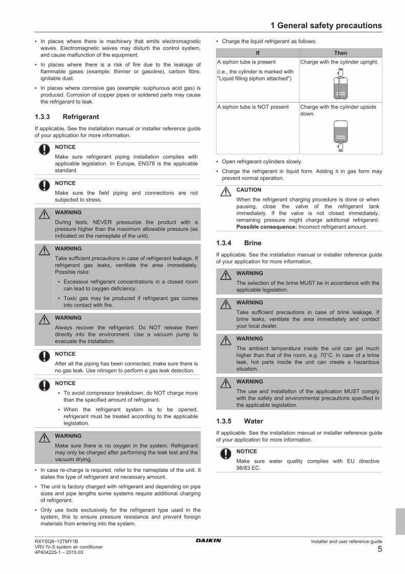
▪ Charge the liquid refrigerant as follows:
If ThenA siphon tube is present
(i.e., the cylinder is marked with"Liquid filling siphon attached")
Charge with the cylinder upright.
A siphon tube is NOT present Charge with the cylinder upsidedown.
▪ Open refrigerant cylinders slowly.
▪ Charge the refrigerant in liquid form. Adding it in gas form mayprevent normal operation.
CAUTION
When the refrigerant charging procedure is done or whenpausing, close the valve of the refrigerant tankimmediately. If the valve is not closed immediately,remaining pressure might charge additional refrigerant.Possible consequence: Incorrect refrigerant amount.
1.3.4 BrineIf applicable. See the installation manual or installer reference guideof your application for more information.
WARNING
The selection of the brine MUST be in accordance with theapplicable legislation.
WARNING
Take sufficient precautions in case of brine leakage. Ifbrine leaks, ventilate the area immediately and contactyour local dealer.
WARNING
The ambient temperature inside the unit can get muchhigher than that of the room, e.g. 70°C. In case of a brineleak, hot parts inside the unit can create a hazardoussituation.
WARNING
The use and installation of the application MUST complywith the safety and environmental precautions specified inthe applicable legislation.
1.3.5 WaterIf applicable. See the installation manual or installer reference guideof your application for more information.
NOTICE
Make sure water quality complies with EU directive98/83 EC.
2 About the documentation
Installer and user reference guide
6RXYSQ8~12TMY1B
VRV IV-S system air conditioner4P404225-1 – 2015.03
1.3.6 Electrical
DANGER: RISK OF ELECTROCUTION
▪ Turn OFF all power supply before removing theswitch box cover, connecting electrical wiring ortouching electrical parts.
▪ Disconnect the power supply for more than 1 minute,and measure the voltage at the terminals of main circuitcapacitors or electrical components before servicing.The voltage MUST be less than 50 V DC before youcan touch electrical components. For the location of theterminals, see the wiring diagram.
▪ Do NOT touch electrical components with wet hands.
▪ Do NOT leave the unit unattended when the servicecover is removed.
WARNING
If NOT factory installed, a main switch or other means fordisconnection, having a contact separation in all polesproviding full disconnection under overvoltage category IIIcondition, shall be installed in the fixed wiring.
WARNING
▪ ONLY use copper wires.
▪ Make sure the field wiring complies with the applicablelegislation.
▪ All field wiring must be performed in accordance withthe wiring diagram supplied with the product.
▪ NEVER squeeze bundled cables and make sure theydo not come in contact with the piping and sharpedges. Make sure no external pressure is applied to theterminal connections.
▪ Make sure to install earth wiring. Do NOT earth the unitto a utility pipe, surge absorber, or telephone earth.Incomplete earth may cause electrical shock.
▪ Make sure to use a dedicated power circuit. NEVERuse a power supply shared by another appliance.
▪ Make sure to install the required fuses or circuitbreakers.
▪ Make sure to install an earth leakage protector. Failureto do so may cause electric shock or fire.
▪ When installing the earth leakage protector, make sureit is compatible with the inverter (resistant to highfrequency electric noise) to avoid unnecessary openingof the earth leakage protector.
Install power cables at least 1 metre away from televisions or radiosto prevent interference. Depending on the radio waves, a distance of1 metre may not be sufficient.
WARNING
▪ After finishing the electrical work, confirm that eachelectrical component and terminal inside the electricalcomponents box is connected securely.
▪ Make sure all covers are closed before starting up theunit.
NOTICE
Only applicable if the power supply is three‑phase, and thecompressor has an ON/OFF starting method.
If there exists the possibility of reversed phase after amomentary black out and the power goes on and off whilethe product is operating, attach a reversed phaseprotection circuit locally. Running the product in reversedphase can break the compressor and other parts.
2 About the documentation
2.1 About this documentTarget audienceAuthorised installers + end users
INFORMATION
This appliance is intended to be used by expert or trainedusers in shops, in light industry and on farms, or forcommercial use by lay persons.
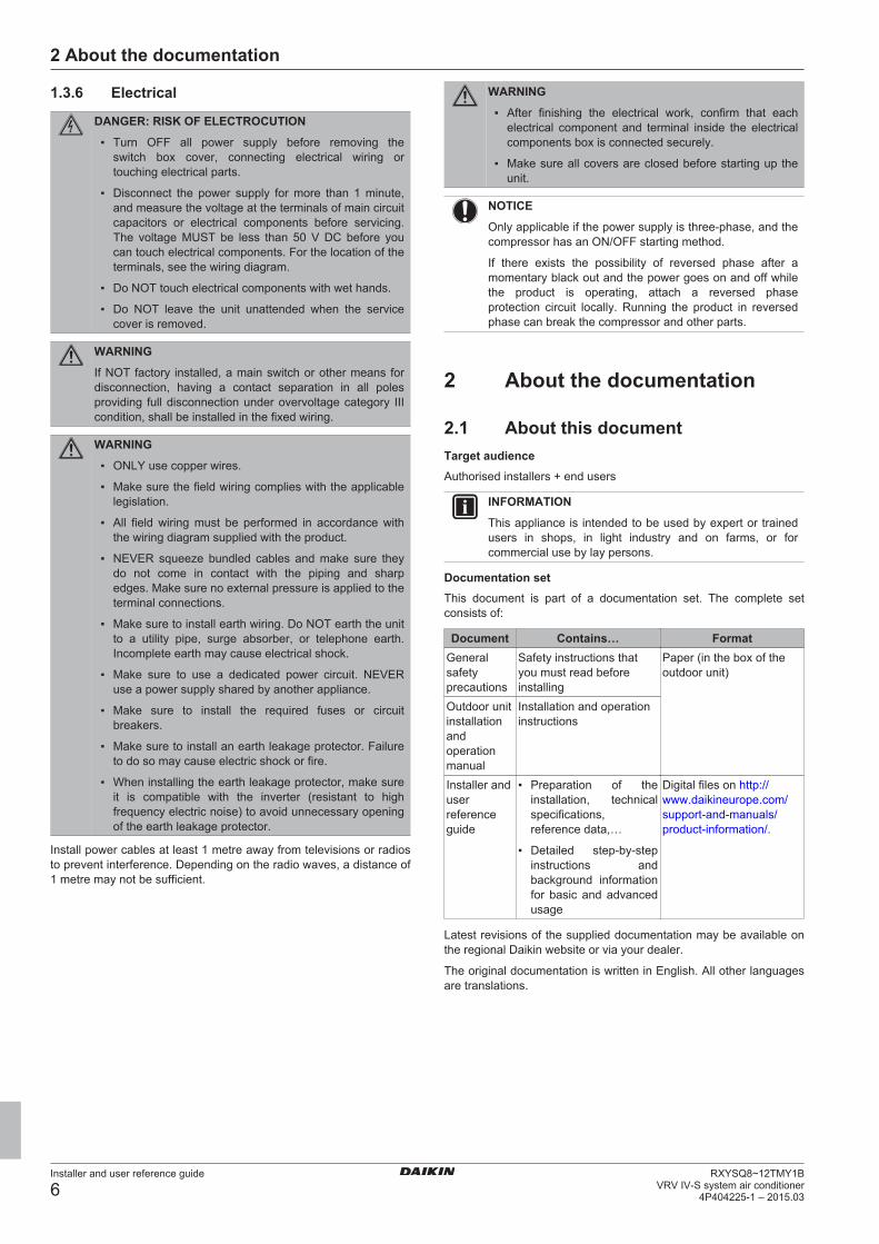
Documentation setThis document is part of a documentation set. The complete setconsists of:
Document Contains… FormatGeneralsafetyprecautions
Safety instructions thatyou must read beforeinstalling
Paper (in the box of theoutdoor unit)
Outdoor unitinstallationandoperationmanual
Installation and operationinstructions
Installer anduserreferenceguide
▪ Preparation of theinstallation, technicalspecifications,reference data,…
▪ Detailed step-by-stepinstructions andbackground informationfor basic and advancedusage
Digital files on http://www.daikineurope.com/support-and-manuals/product-information/.
Latest revisions of the supplied documentation may be available onthe regional Daikin website or via your dealer.
The original documentation is written in English. All other languagesare translations.
3 For the installer
Installer and user reference guide
7RXYSQ8~12TMY1BVRV IV-S system air conditioner4P404225-1 – 2015.03
For the installer
3 About the box
3.1 Overview: About the boxThis chapter describes what you have to do after the box with theoutdoor unit is delivered on-site.
It contains information about:
▪ Unpacking and handling the units
▪ Removing the accessories from the units
▪ Removing the transportation stay
Keep the following in mind:
▪ At delivery, the unit must be checked for damage. Any damagemust be reported immediately to the carrier's claims agent.
▪ Bring the packed unit as close as possible to its final installationposition to prevent damage during transport.
▪ When handling the unit, take into account the following:
Fragile, handle the unit with care.
Keep the unit upright in order to avoid compressordamage.
▪ Choose on beforehand the path along which the unit is to bebrought in.
3.2 Outdoor unit
3.2.1 To unpack the outdoor unit
21
3
1
2
1×
8 HP
21
4×
10+12 HP
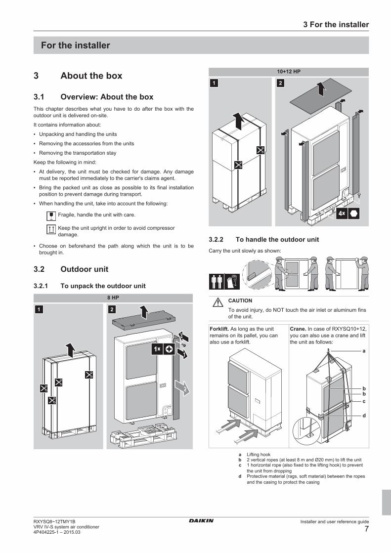
3.2.2 To handle the outdoor unitCarry the unit slowly as shown:
CAUTION
To avoid injury, do NOT touch the air inlet or aluminum finsof the unit.
Forklift. As long as the unitremains on its pallet, you canalso use a forklift.
Crane. In case of RXYSQ10+12,you can also use a crane and liftthe unit as follows:
c
b
a
b
d
a Lifting hookb 2 vertical ropes (at least 8 m and Ø20 mm) to lift the unitc 1 horizontal rope (also fixed to the lifting hook) to prevent
the unit from droppingd Protective material (rags, soft material) between the ropes
and the casing to protect the casing
4 About the units and options
Installer and user reference guide
8RXYSQ8~12TMY1B
VRV IV-S system air conditioner4P404225-1 – 2015.03
WARNING
The unit's center of gravity deviates to the right side(compressor side). If you lift the unit using a crane and youdo not fix a horizontal rope to the lifting hook as shown, theunit might drop.
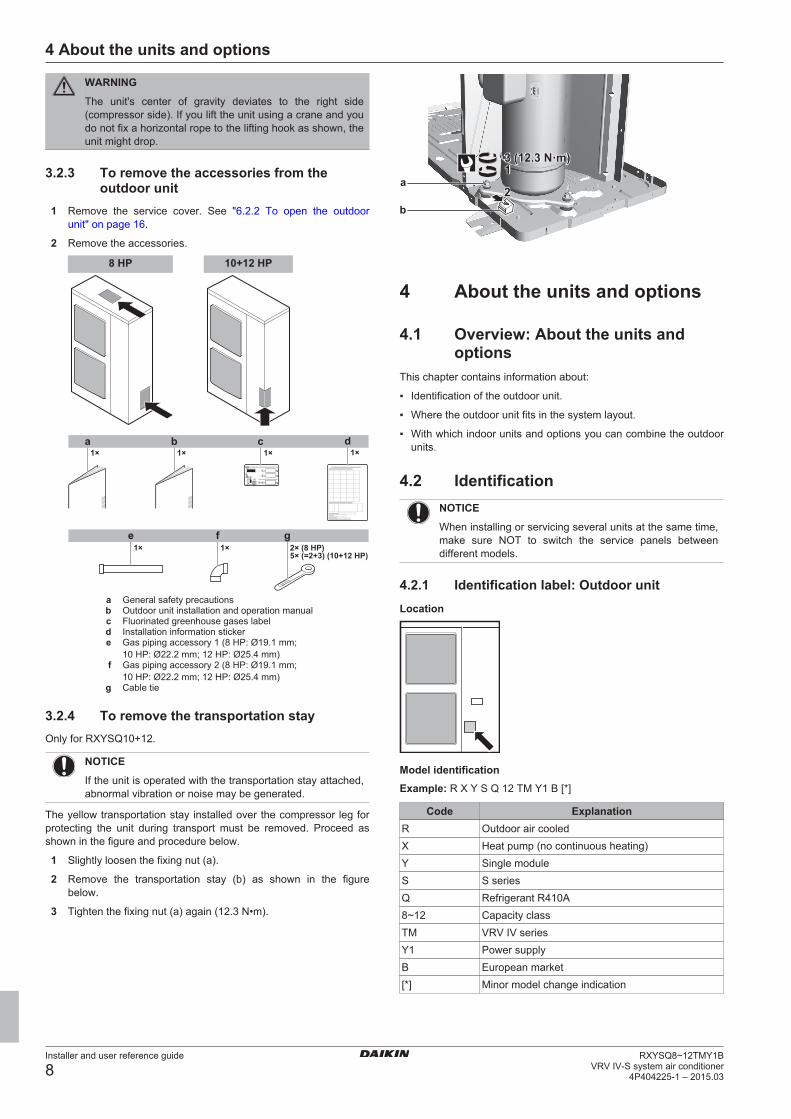
3.2.3 To remove the accessories from theoutdoor unit
1 Remove the service cover. See "6.2.2 To open the outdoorunit" on page 16.
2 Remove the accessories.
8 HP 10+12 HP
a1×
b1×
c1×
d1×
2× (8 HP)5× (=2+3) (10+12 HP)
1×e f g
1×
a General safety precautionsb Outdoor unit installation and operation manualc Fluorinated greenhouse gases labeld Installation information stickere Gas piping accessory 1 (8 HP: Ø19.1 mm;
10 HP: Ø22.2 mm; 12 HP: Ø25.4 mm)f Gas piping accessory 2 (8 HP: Ø19.1 mm;
10 HP: Ø22.2 mm; 12 HP: Ø25.4 mm)g Cable tie
3.2.4 To remove the transportation stayOnly for RXYSQ10+12.
NOTICE
If the unit is operated with the transportation stay attached,abnormal vibration or noise may be generated.
The yellow transportation stay installed over the compressor leg forprotecting the unit during transport must be removed. Proceed asshown in the figure and procedure below.
1 Slightly loosen the fixing nut (a).
2 Remove the transportation stay (b) as shown in the figurebelow.
3 Tighten the fixing nut (a) again (12.3 N•m).
13 (12.3 N·m)3 (12.3 N·m)
22
1a
b
4 About the units and options
4.1 Overview: About the units andoptions
This chapter contains information about:
▪ Identification of the outdoor unit.
▪ Where the outdoor unit fits in the system layout.
▪ With which indoor units and options you can combine the outdoorunits.
4.2 IdentificationNOTICE
When installing or servicing several units at the same time,make sure NOT to switch the service panels betweendifferent models.
4.2.1 Identification label: Outdoor unitLocation
Model identificationExample: R X Y S Q 12 TM Y1 B [*]
Code ExplanationR Outdoor air cooledX Heat pump (no continuous heating)Y Single moduleS S seriesQ Refrigerant R410A8~12 Capacity classTM VRV IV seriesY1 Power supplyB European market[*] Minor model change indication
5 Preparation
Installer and user reference guide
9RXYSQ8~12TMY1BVRV IV-S system air conditioner4P404225-1 – 2015.03
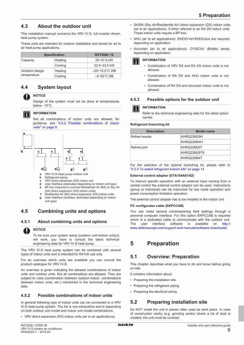
4.3 About the outdoor unitThis installation manual concerns the VRV IV-S, full inverter driven,heat pump system.
These units are intended for outdoor installation and aimed for air toair heat pump applications.
Specification RXYSQ8~12Capacity Heating 25~37.5 kW
Cooling 22.4~33.5 kWAmbient designtemperature
Heating –20~15.5°C WBCooling –5~52°C DB
4.4 System layoutNOTICE
Design of the system must not be done at temperaturesbelow –15°C.
INFORMATION
Not all combinations of indoor units are allowed, forguidance, see "4.5.2 Possible combinations of indoorunits" on page 9.
gd d
c c
f
eb
a
g
f
e
a VRV IV-S Heat pump outdoor unitb Refrigerant pipingc VRV direct expansion (DX) indoor unitd User interface (dedicated depending on indoor unit type)e BP box (required to connect Residential Air (RA) or Sky Air
(SA) direct expansion (DX) indoor units)f Residential Air (RA) direct expansion (DX) indoor unitsg User interface (wireless, dedicated depending on indoor
unit type)
4.5 Combining units and options
4.5.1 About combining units and options
NOTICE
To be sure your system setup (outdoor unit+indoor unit(s))will work, you have to consult the latest technicalengineering data for VRV IV-S heat pump.
The VRV IV-S heat pump system can be combined with severaltypes of indoor units and is intended for R410A use only.
For an overview which units are available you can consult theproduct catalogue for VRV IV-S.
An overview is given indicating the allowed combinations of indoorunits and outdoor units. Not all combinations are allowed. They aresubject to rules (combination between outdoor-indoor, combinationsbetween indoor units, etc.) mentioned in the technical engineeringdata.
4.5.2 Possible combinations of indoor unitsIn general following type of indoor units can be connected to a VRVIV-S heat pump system. The list is non-exhaustive and is dependingon both outdoor unit model and indoor unit model combinations.
▪ VRV direct expansion (DX) indoor units (air to air applications).
▪ SA/RA (Sky Air/Residential Air) direct expansion (DX) indoor units(air to air applications). Further referred to as RA DX indoor units.These indoor units require a BP box.
▪ AHU (air to air applications): EKEXV-kit+EKEQ-box are required,depending on application.
▪ Aircurtain (air to air applications): CYQ/CAV (Biddle) series,depending on application.
INFORMATION
▪ Combination of VRV DX and RA DX indoor units is notallowed.
▪ Combination of RA DX and AHU indoor units is notallowed.
▪ Combination of RA DX and aircurtain indoor units is notallowed.
4.5.3 Possible options for the outdoor unit
INFORMATION
Refer to the technical engineering data for the latest optionnames.
Refrigerant branching kit
Description Model nameRefnet header KHRQ22M29H
KHRQ22M64HRefnet joint KHRQ22M20T
KHRQ22M29T9KHRQ22M64T
For the selection of the optimal branching kit, please refer to"5.3.4 To select refrigerant branch kits" on page 14.
External control adaptor (DTA104A61/62)To instruct specific operation with an external input coming from acentral control the external control adaptor can be used. Instructions(group or individual) can be instructed for low noise operation andpower consumption limitation operation.
The external control adapter has to be installed in the indoor unit.
PC configurator cable (EKPCCAB)You can make several commissioning field settings through apersonal computer interface. For this option EKPCCAB is requiredwhich is a dedicated cable to communicate with the outdoor unit.The user interface software is available on http://www.daikineurope.com/support-and-manuals/software-downloads/.
5 Preparation
5.1 Overview: PreparationThis chapter describes what you have to do and know before goingon-site.
It contains information about:
▪ Preparing the installation site
▪ Preparing the refrigerant piping
▪ Preparing the electrical wiring
5.2 Preparing installation siteDo NOT install the unit in places often used as work place. In caseof construction works (e.g. grinding works) where a lot of dust iscreated, the unit must be covered.
5 Preparation
Installer and user reference guide
10RXYSQ8~12TMY1B
VRV IV-S system air conditioner4P404225-1 – 2015.03
Choose the installation location with sufficient place for carrying theunit in and out of the site.
5.2.1 Installation site requirements of theoutdoor unit
INFORMATION
Also read the following requirements:
▪ General installation site requirements. See the"General safety precautions" chapter.
▪ Service space requirements. See the "Technical data"chapter.
▪ Refrigerant piping requirements (length, heightdifference). See further in this "Preparation" chapter.
CAUTION
Appliance not accessible to the general public, install it in asecured area, protected from easy access.
This unit, both indoor and outdoor, is suitable forinstallation in a commercial and light industrialenvironment.
NOTICE
This is a class A product. In a domestic environment thisproduct may cause radio interference in which case theuser may be required to take adequate measures.
NOTICE
The equipment described in this manual may causeelectronic noise generated from radio-frequency energy.The equipment complies to specifications that aredesigned to provide reasonable protection against suchinterference. However, there is no guarantee thatinterference will not occur in a particular installation.
It is therefore recommended to install the equipment andelectric wires keeping proper distances away from stereoequipment, personal computers, etc.
b
c
f
dd
a
cb e (mm)
a Personal computer or radiob Fusec Earth leakage protectord User interfacee Indoor unitf Outdoor unit
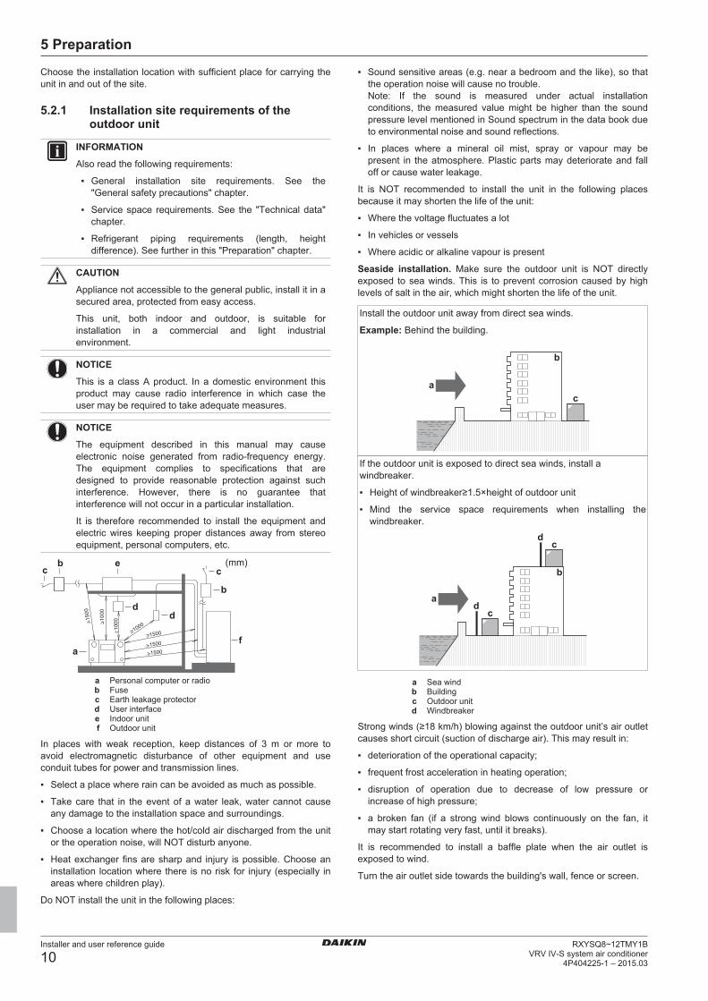
In places with weak reception, keep distances of 3 m or more toavoid electromagnetic disturbance of other equipment and useconduit tubes for power and transmission lines.
▪ Select a place where rain can be avoided as much as possible.
▪ Take care that in the event of a water leak, water cannot causeany damage to the installation space and surroundings.
▪ Choose a location where the hot/cold air discharged from the unitor the operation noise, will NOT disturb anyone.
▪ Heat exchanger fins are sharp and injury is possible. Choose aninstallation location where there is no risk for injury (especially inareas where children play).
Do NOT install the unit in the following places:
▪ Sound sensitive areas (e.g. near a bedroom and the like), so thatthe operation noise will cause no trouble.Note: If the sound is measured under actual installationconditions, the measured value might be higher than the soundpressure level mentioned in Sound spectrum in the data book dueto environmental noise and sound reflections.
▪ In places where a mineral oil mist, spray or vapour may bepresent in the atmosphere. Plastic parts may deteriorate and falloff or cause water leakage.
It is NOT recommended to install the unit in the following placesbecause it may shorten the life of the unit:
▪ Where the voltage fluctuates a lot
▪ In vehicles or vessels
▪ Where acidic or alkaline vapour is present
Seaside installation. Make sure the outdoor unit is NOT directlyexposed to sea winds. This is to prevent corrosion caused by highlevels of salt in the air, which might shorten the life of the unit.
Install the outdoor unit away from direct sea winds.
Example: Behind the building.
b
ca
If the outdoor unit is exposed to direct sea winds, install awindbreaker.
▪ Height of windbreaker≥1.5×height of outdoor unit
▪ Mind the service space requirements when installing thewindbreaker.
a
b
cd
cd
a Sea windb Buildingc Outdoor unitd Windbreaker
Strong winds (≥18 km/h) blowing against the outdoor unit’s air outletcauses short circuit (suction of discharge air). This may result in:
▪ deterioration of the operational capacity;
▪ frequent frost acceleration in heating operation;
▪ disruption of operation due to decrease of low pressure orincrease of high pressure;
▪ a broken fan (if a strong wind blows continuously on the fan, itmay start rotating very fast, until it breaks).
It is recommended to install a baffle plate when the air outlet isexposed to wind.
Turn the air outlet side towards the building's wall, fence or screen.
5 Preparation
Installer and user reference guide
11RXYSQ8~12TMY1BVRV IV-S system air conditioner4P404225-1 – 2015.03
a
a Make sure there is enough installation space
Set the air outlet side at a right angle to the direction of the wind.
a
ab
a Prevailing wind directionb Air outlet
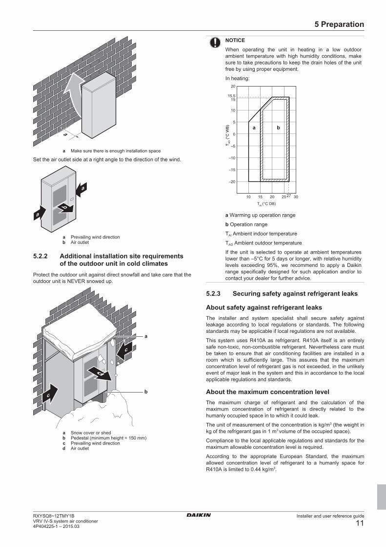
5.2.2 Additional installation site requirementsof the outdoor unit in cold climates
Protect the outdoor unit against direct snowfall and take care that theoutdoor unit is NEVER snowed up.
a
bc
c
d
a Snow cover or shedb Pedestal (minimum height = 150 mm)c Prevailing wind directiond Air outlet
NOTICE
When operating the unit in heating in a low outdoorambient temperature with high humidity conditions, makesure to take precautions to keep the drain holes of the unitfree by using proper equipment.
In heating:
T AO (°
C W
B) a b
20
15.515
10
5
0
–5
–10
–15
–20
10 15 20 25 27 30
TAI (°C DB)
a Warming up operation range
b Operation range
TAI Ambient indoor temperature
TAO Ambient outdoor temperature
If the unit is selected to operate at ambient temperatureslower than –5°C for 5 days or longer, with relative humiditylevels exceeding 95%, we recommend to apply a Daikinrange specifically designed for such application and/or tocontact your dealer for further advice.
5.2.3 Securing safety against refrigerant leaks
About safety against refrigerant leaksThe installer and system specialist shall secure safety againstleakage according to local regulations or standards. The followingstandards may be applicable if local regulations are not available.
This system uses R410A as refrigerant. R410A itself is an entirelysafe non-toxic, non-combustible refrigerant. Nevertheless care mustbe taken to ensure that air conditioning facilities are installed in aroom which is sufficiently large. This assures that the maximumconcentration level of refrigerant gas is not exceeded, in the unlikelyevent of major leak in the system and this in accordance to the localapplicable regulations and standards.
About the maximum concentration levelThe maximum charge of refrigerant and the calculation of themaximum concentration of refrigerant is directly related to thehumanly occupied space in to which it could leak.
The unit of measurement of the concentration is kg/m3 (the weight inkg of the refrigerant gas in 1 m3 volume of the occupied space).
Compliance to the local applicable regulations and standards for themaximum allowable concentration level is required.
According to the appropriate European Standard, the maximumallowed concentration level of refrigerant to a humanly space forR410A is limited to 0.44 kg/m3.
5 Preparation
Installer and user reference guide
12RXYSQ8~12TMY1B
VRV IV-S system air conditioner4P404225-1 – 2015.03
b
a
a Direction of the refrigerant flowb Room where refrigerant leak has occurred (outflow of all
the refrigerant from the system)
Pay special attention to places, such as basements etc., whererefrigerant can stay, since refrigerant is heavier than air.
To check the maximum concentration levelCheck the maximum concentration level in accordance with steps 1to 4 below and take whatever action is necessary to comply.
1 Calculate the amount of refrigerant (kg) charged to each systemseparately.
Formula A+B=CA Amount of refrigerant in a single unit system
(amount of refrigerant with which the system ischarged before leaving the factory)
B Additional charging amount (amount ofrefrigerant added locally in accordance with thelength or diameter of the refrigerant piping)
C Total amount of refrigerant (kg) in the system
NOTICE
Where a single refrigerant facility is divided into 2 entirelyindependent refrigerant systems, use the amount ofrefrigerant with which each separate system is charged.
2 Calculate the volume of the room (m3) where the indoor unit isinstalled. In a case such as the following, calculate the volumeof (A), (B) as a single room or as the smallest room.
A Where there are no smaller room divisions:
B Where there is a room division, but there is an openingbetween the rooms sufficiently large to permit a free flow of airback and forth.
ab
a Opening between the rooms
b Partition (Where there is an opening without a door or wherethere are openings above and below the door which are eachequivalent in size to 0.15% or more of the floor area.)
3 Calculate the refrigerant density using the results of thecalculations in steps 1 and 2 above. If the result of the abovecalculation exceeds the maximum concentration level, aventilation opening to the adjacent room shall be made.
Formula A/B≤CA Total volume of refrigerant in the refrigerant
systemB Size (m3) of smallest room in which there is an
indoor unit installedC Maximum concentration level (kg/m3)
4 Calculate the refrigerant density taking the volume of the roomwhere the indoor unit is installed and the adjacent room. Installventilation openings in the door of adjacent rooms until therefrigerant density is smaller than the maximum concentrationlevel.
5.3 Preparing refrigerant piping
5.3.1 Refrigerant piping requirements
INFORMATION
Also read the precautions and requirements in the"General safety precautions" chapter.
NOTICE
The refrigerant R410A requires strict cautions for keepingthe system clean, dry and tight.
▪ Clean and dry: foreign materials (including mineral oilsor moisture) should be prevented from getting mixedinto the system.
▪ Tight: R410A does not contain any chlorine, does notdestroy the ozone layer, and does not reduce earth'sprotection against harmful ultraviolet radiation. R410Acan contribute slightly to the greenhouse effect if it isreleased. Therefore we should take special attention tocheck the tightness of the installation.
NOTICE
The piping and other pressure-containing parts shall besuitable for refrigerant. Use phosphoric acid deoxidisedseamless copper for refrigerant.
▪ Foreign materials inside pipes (including oils for fabrication) mustbe ≤30 mg/10 m.
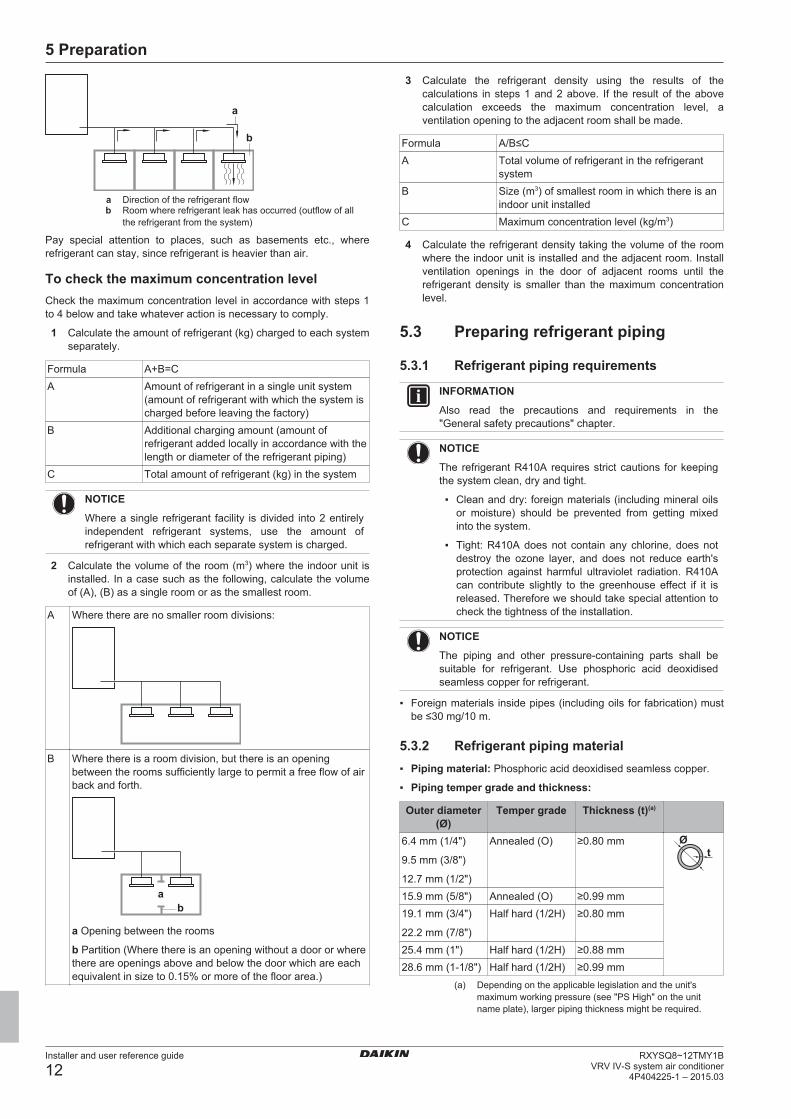
5.3.2 Refrigerant piping material▪ Piping material: Phosphoric acid deoxidised seamless copper.
▪ Piping temper grade and thickness:
Outer diameter(Ø)
Temper grade Thickness (t)(a)
6.4 mm (1/4")
9.5 mm (3/8")
12.7 mm (1/2")
Annealed (O) ≥0.80 mmt
Ø
15.9 mm (5/8") Annealed (O) ≥0.99 mm19.1 mm (3/4")
22.2 mm (7/8")
Half hard (1/2H) ≥0.80 mm
25.4 mm (1") Half hard (1/2H) ≥0.88 mm28.6 mm (1‑1/8") Half hard (1/2H) ≥0.99 mm
(a) Depending on the applicable legislation and the unit'smaximum working pressure (see "PS High" on the unitname plate), larger piping thickness might be required.
5 Preparation
Installer and user reference guide
13RXYSQ8~12TMY1BVRV IV-S system air conditioner4P404225-1 – 2015.03
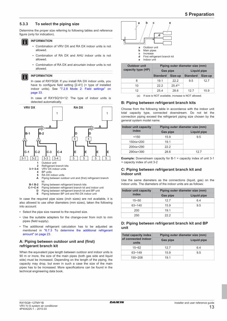
5.3.3 To select the piping sizeDetermine the proper size referring to following tables and referencefigure (only for indication).
INFORMATION
▪ Combination of VRV DX and RA DX indoor units is notallowed.
▪ Combination of RA DX and AHU indoor units is notallowed.
▪ Combination of RA DX and aircurtain indoor units is notallowed.
INFORMATION
In case of RXYSQ8: If you install RA DX indoor units, youhave to configure field setting [2‑41] (= type of installedindoor units). See "7.2.8 Mode 2: Field settings" onpage 33.
In case of RXYSQ10+12: The type of indoor units isdetected automatically.
A
B-1 B-2
C-1 C-2 C-3 C-4 E E E E
1 1
3-1 3-2 3-3 3-4
A
D
RA DXVRV DX
D
44
5 5 5 5
2 2
2 2
1 Outdoor unit2 Refrigerant branch kits
3-1~3-4 VRV DX indoor units4 BP units5 RA DX indoor unitsA Piping between outdoor unit and (first) refrigerant branch
kitB-1 B-2 Piping between refrigerant branch kits
C-1~C-4 Piping between refrigerant branch kit and indoor unitD Piping between refrigerant branch kit and BP unitE Piping between BP unit and RA DX indoor unit
In case the required pipe sizes (inch sizes) are not available, it isalso allowed to use other diameters (mm sizes), taken the followinginto account:
▪ Select the pipe size nearest to the required size.
▪ Use the suitable adapters for the change-over from inch to mmpipes (field supply).
▪ The additional refrigerant calculation has to be adjusted asmentioned in "6.7.3 To determine the additional refrigerantamount" on page 23.
A: Piping between outdoor unit and (first)refrigerant branch kitWhen the equivalent pipe length between outdoor and indoor units is90 m or more, the size of the main pipes (both gas side and liquidside) must be increased. Depending on the length of the piping, thecapacity may drop, but even in such a case the size of the mainpipes has to be increased. More specifications can be found in thetechnical engineering data book.
a eb c
d
a Outdoor unitb Main pipesc Increased First refrigerant branch kite Indoor unit
Outdoor unitcapacity type (HP)
Piping outer diameter size (mm)Gas pipe Liquid pipe
Standard Size-up Standard Size-up8 19.1 22.2 9.5 12.7
10 22.2 25.4(a)
12 25.4 28.6 12.7 15.9(a) If size is NOT available, increase is NOT allowed.
B: Piping between refrigerant branch kitsChoose from the following table in accordance with the indoor unittotal capacity type, connected downstream. Do not let theconnection piping exceed the refrigerant piping size chosen by thegeneral system model name.
Indoor unit capacityindex
Piping outer diameter size (mm)Gas pipe Liquid pipe
<150 15.9 9.5150≤x<200 19.1200≤x<290 22.2290≤x<390 28.6 12.7
Example: Downstream capacity for B-1 = capacity index of unit 3-1+ capacity index of unit 3-2
C: Piping between refrigerant branch kit andindoor unitUse the same diameters as the connections (liquid, gas) on theindoor units. The diameters of the indoor units are as follows:
Indoor unit capacityindex
Piping outer diameter size (mm)Gas pipe Liquid pipe
15~50 12.7 6.463~140 15.9 9.5
200 19.1250 22.2
D: Piping between refrigerant branch kit and BPunit
Total capacity indexof connected indoor
units
Piping outer diameter size (mm)Gas pipe Liquid pipe
15~62 12.7 6.463~149 15.9 9.5
150~208 19.1
5 Preparation
Installer and user reference guide
14RXYSQ8~12TMY1B
VRV IV-S system air conditioner4P404225-1 – 2015.03
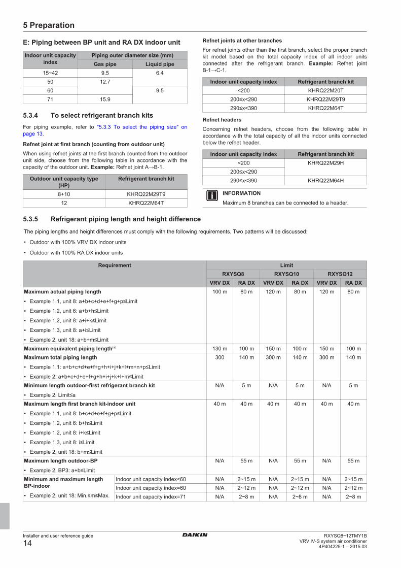
E: Piping between BP unit and RA DX indoor unit
Indoor unit capacityindex
Piping outer diameter size (mm)Gas pipe Liquid pipe
15~42 9.5 6.450 12.760 9.571 15.9
5.3.4 To select refrigerant branch kitsFor piping example, refer to "5.3.3 To select the piping size" onpage 13.
Refnet joint at first branch (counting from outdoor unit)When using refnet joints at the first branch counted from the outdoorunit side, choose from the following table in accordance with thecapacity of the outdoor unit. Example: Refnet joint A→B‑1.
Outdoor unit capacity type(HP)
Refrigerant branch kit
8+10 KHRQ22M29T912 KHRQ22M64T
Refnet joints at other branchesFor refnet joints other than the first branch, select the proper branchkit model based on the total capacity index of all indoor unitsconnected after the refrigerant branch. Example: Refnet jointB‑1→C‑1.
Indoor unit capacity index Refrigerant branch kit<200 KHRQ22M20T
200≤x<290 KHRQ22M29T9290≤x<390 KHRQ22M64T
Refnet headersConcerning refnet headers, choose from the following table inaccordance with the total capacity of all the indoor units connectedbelow the refnet header.
Indoor unit capacity index Refrigerant branch kit<200 KHRQ22M29H
200≤x<290290≤x<390 KHRQ22M64H
INFORMATION
Maximum 8 branches can be connected to a header.
5.3.5 Refrigerant piping length and height difference
The piping lengths and height differences must comply with the following requirements. Two patterns will be discussed:
• Outdoor with 100% VRV DX indoor units
• Outdoor with 100% RA DX indoor units
Requirement LimitRXYSQ8 RXYSQ10 RXYSQ12
VRV DX RA DX VRV DX RA DX VRV DX RA DXMaximum actual piping length
▪ Example 1.1, unit 8: a+b+c+d+e+f+g+p≤Limit
▪ Example 1.2, unit 6: a+b+h≤Limit
▪ Example 1.2, unit 8: a+i+k≤Limit
▪ Example 1.3, unit 8: a+i≤Limit
▪ Example 2, unit 18: a+b+m≤Limit
100 m 80 m 120 m 80 m 120 m 80 m
Maximum equivalent piping length(a) 130 m 100 m 150 m 100 m 150 m 100 mMaximum total piping length
▪ Example 1.1: a+b+c+d+e+f+g+h+i+j+k+l+m+n+p≤Limit
▪ Example 2: a+b+c+d+e+f+g+h+i+j+k+l+m≤Limit
300 140 m 300 m 140 m 300 m 140 m
Minimum length outdoor-first refrigerant branch kit
▪ Example 2: Limit≤a
N/A 5 m N/A 5 m N/A 5 m
Maximum length first branch kit-indoor unit
▪ Example 1.1, unit 8: b+c+d+e+f+g+p≤Limit
▪ Example 1.2, unit 6: b+h≤Limit
▪ Example 1.2, unit 8: i+k≤Limit
▪ Example 1.3, unit 8: i≤Limit
▪ Example 2, unit 18: b+m≤Limit
40 m 40 m 40 m 40 m 40 m 40 m
Maximum length outdoor-BP
▪ Example 2, BP3: a+b≤Limit
N/A 55 m N/A 55 m N/A 55 m
Minimum and maximum lengthBP-indoor
▪ Example 2, unit 18: Min.≤m≤Max.
Indoor unit capacity index<60 N/A 2~15 m N/A 2~15 m N/A 2~15 mIndoor unit capacity index=60 N/A 2~12 m N/A 2~12 m N/A 2~12 mIndoor unit capacity index=71 N/A 2~8 m N/A 2~8 m N/A 2~8 m
5 Preparation
Installer and user reference guide
15RXYSQ8~12TMY1BVRV IV-S system air conditioner4P404225-1 – 2015.03
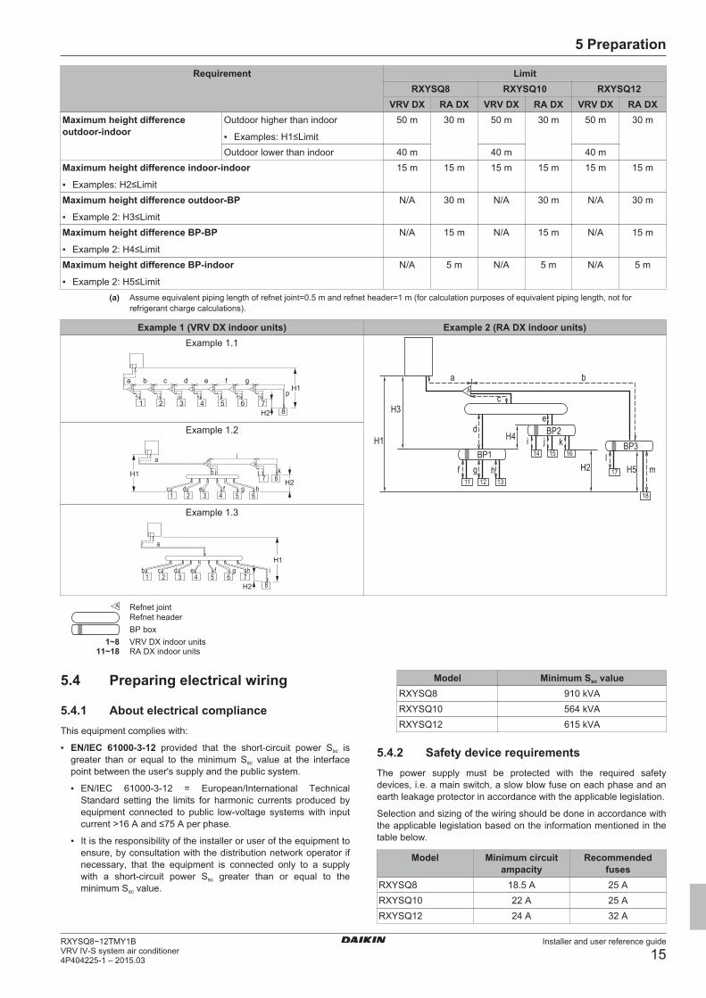
Requirement LimitRXYSQ8 RXYSQ10 RXYSQ12
VRV DX RA DX VRV DX RA DX VRV DX RA DXMaximum height differenceoutdoor-indoor
Outdoor higher than indoor
▪ Examples: H1≤Limit
50 m 30 m 50 m 30 m 50 m 30 m
Outdoor lower than indoor 40 m 40 m 40 mMaximum height difference indoor-indoor
▪ Examples: H2≤Limit
15 m 15 m 15 m 15 m 15 m 15 m
Maximum height difference outdoor-BP
▪ Example 2: H3≤Limit
N/A 30 m N/A 30 m N/A 30 m
Maximum height difference BP-BP
▪ Example 2: H4≤Limit
N/A 15 m N/A 15 m N/A 15 m
Maximum height difference BP-indoor
▪ Example 2: H5≤Limit
N/A 5 m N/A 5 m N/A 5 m
(a) Assume equivalent piping length of refnet joint=0.5 m and refnet header=1 m (for calculation purposes of equivalent piping length, not forrefrigerant charge calculations).
Example 1 (VRV DX indoor units) Example 2 (RA DX indoor units)Example 1.1
aA
h i j k l m nB C D E F G
p
b c d e f
1 2 3 4 5 6 78
gH1
H2 H3
a
c
d
f
H1BP1
g h
bA
lm
BP3
18
17131211
H4
e
iBP2
j k161514
H2 H5
Example 1.2
ab
c d e f
i
kj
g h
A B
1 2 3 4 5 6
7 8H1H2
Example 1.3
a
cb d e f ig h1 2 3 4 5 6 7
8
H1
H2
Refnet jointRefnet headerBP box
1~8 VRV DX indoor units11~18 RA DX indoor units
5.4 Preparing electrical wiring
5.4.1 About electrical complianceThis equipment complies with:
▪ EN/IEC 61000‑3‑12 provided that the short-circuit power Ssc isgreater than or equal to the minimum Ssc value at the interfacepoint between the user's supply and the public system.
▪ EN/IEC 61000‑3‑12 = European/International TechnicalStandard setting the limits for harmonic currents produced byequipment connected to public low-voltage systems with inputcurrent >16 A and ≤75 A per phase.
▪ It is the responsibility of the installer or user of the equipment toensure, by consultation with the distribution network operator ifnecessary, that the equipment is connected only to a supplywith a short-circuit power Ssc greater than or equal to theminimum Ssc value.
Model Minimum Ssc valueRXYSQ8 910 kVARXYSQ10 564 kVARXYSQ12 615 kVA
5.4.2 Safety device requirementsThe power supply must be protected with the required safetydevices, i.e. a main switch, a slow blow fuse on each phase and anearth leakage protector in accordance with the applicable legislation.
Selection and sizing of the wiring should be done in accordance withthe applicable legislation based on the information mentioned in thetable below.
Model Minimum circuitampacity
Recommendedfuses
RXYSQ8 18.5 A 25 ARXYSQ10 22 A 25 ARXYSQ12 24 A 32 A
6 Installation
Installer and user reference guide
16RXYSQ8~12TMY1B
VRV IV-S system air conditioner4P404225-1 – 2015.03
For all models:
▪ Phase and frequency: 3N~ 50 Hz
▪ Voltage: 380-415 V
▪ Transmission line section:
Transmission wiring Vinyl cords with 0.75 to1.25 mm² sheath or cables
(2‑core wires)Maximum wiring length
(= distance between outdoorand furthest indoor unit)
300 m
Total wiring length
(= distance between outdoorand all indoors)
600 m
If the total transmission wiring exceeds these limits, it mayresult in communication error.
6 Installation
6.1 Overview: InstallationThis chapter describes what you have to do and know on-site toinstall the system.
Typical workflowInstallation typically consists of the following stages:
▪ Mounting the outdoor unit.
▪ Mounting the indoor units.
▪ Connecting the refrigerant piping.
▪ Checking the refrigerant piping.
▪ Charging refrigerant.
▪ Connecting the electrical wiring.
▪ Finishing the outdoor installation.
▪ Finishing the indoor installation.
INFORMATION
For installation of the indoor unit (mounting the indoor unit,connecting the refrigerant piping to the indoor unit,connecting the electrical wiring to the indoor unit …), seethe installation manual of the indoor unit.
6.2 Opening the units
6.2.1 About opening the unitsAt certain times, you have to open the unit. Example:
▪ When connecting the refrigerant piping
▪ When connecting the electrical wiring
▪ When maintaining or servicing the unit
DANGER: RISK OF ELECTROCUTION
Do NOT leave the unit unattended when the service coveris removed.
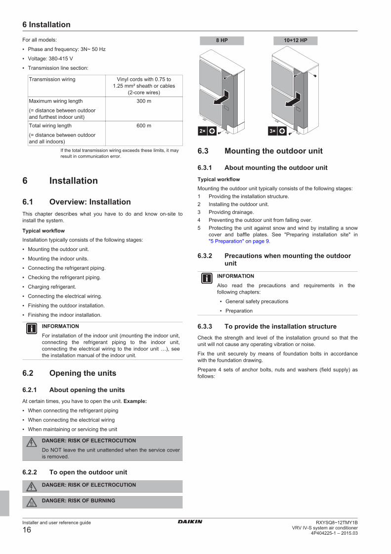
6.2.2 To open the outdoor unit
DANGER: RISK OF ELECTROCUTION
DANGER: RISK OF BURNING
2× 3×
8 HP 10+12 HP
6.3 Mounting the outdoor unit
6.3.1 About mounting the outdoor unitTypical workflowMounting the outdoor unit typically consists of the following stages:1 Providing the installation structure.2 Installing the outdoor unit.3 Providing drainage.4 Preventing the outdoor unit from falling over.5 Protecting the unit against snow and wind by installing a snow
cover and baffle plates. See "Preparing installation site" in"5 Preparation" on page 9.
6.3.2 Precautions when mounting the outdoorunit
INFORMATION
Also read the precautions and requirements in thefollowing chapters:
▪ General safety precautions
▪ Preparation
6.3.3 To provide the installation structureCheck the strength and level of the installation ground so that theunit will not cause any operating vibration or noise.
Fix the unit securely by means of foundation bolts in accordancewith the foundation drawing.
Prepare 4 sets of anchor bolts, nuts and washers (field supply) asfollows:
6 Installation
Installer and user reference guide
17RXYSQ8~12TMY1BVRV IV-S system air conditioner4P404225-1 – 2015.03
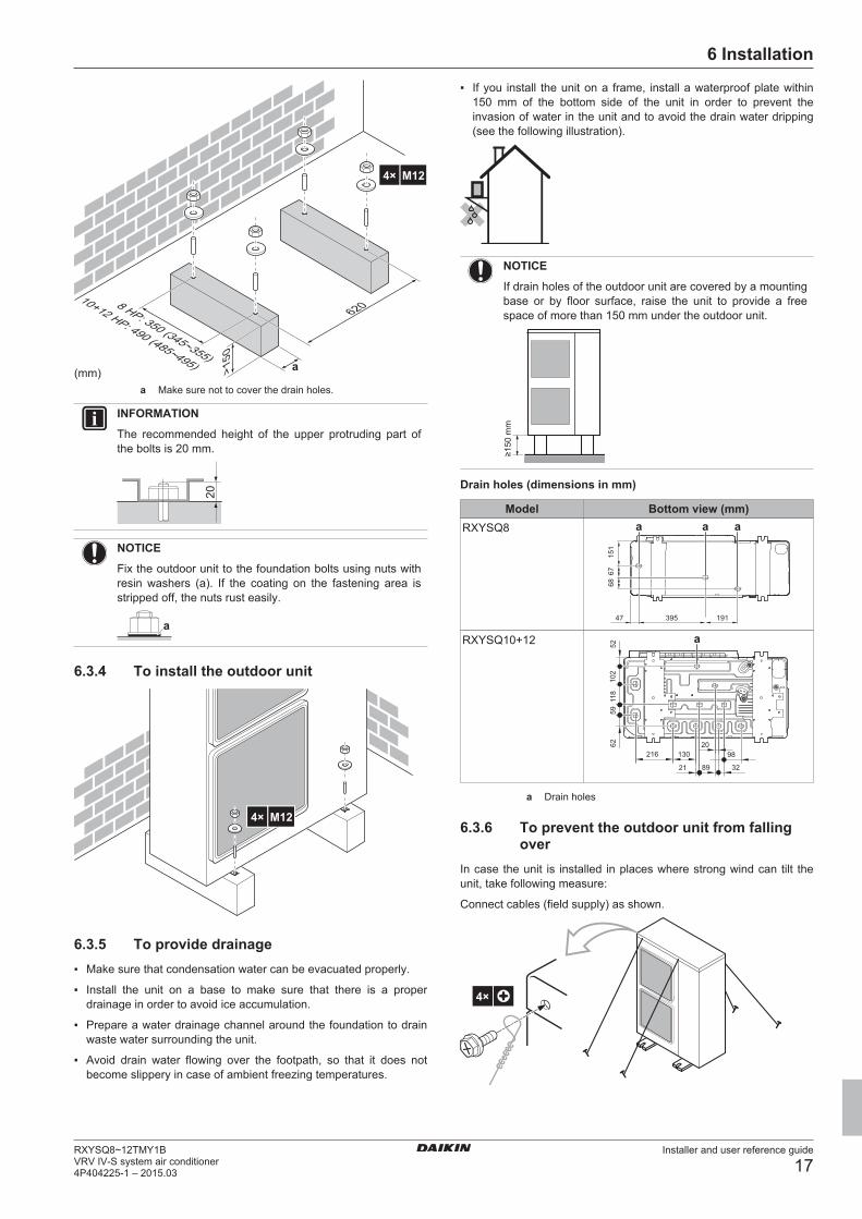
(mm) >150
6208 HP: 350 (345~355)
10+12 HP: 490 (485~495)
4× M12
a
a Make sure not to cover the drain holes.
INFORMATION
The recommended height of the upper protruding part ofthe bolts is 20 mm.
20
NOTICE
Fix the outdoor unit to the foundation bolts using nuts withresin washers (a). If the coating on the fastening area isstripped off, the nuts rust easily.
a
6.3.4 To install the outdoor unit
4× M12
6.3.5 To provide drainage▪ Make sure that condensation water can be evacuated properly.
▪ Install the unit on a base to make sure that there is a properdrainage in order to avoid ice accumulation.
▪ Prepare a water drainage channel around the foundation to drainwaste water surrounding the unit.
▪ Avoid drain water flowing over the footpath, so that it does notbecome slippery in case of ambient freezing temperatures.
▪ If you install the unit on a frame, install a waterproof plate within150 mm of the bottom side of the unit in order to prevent theinvasion of water in the unit and to avoid the drain water dripping(see the following illustration).
NOTICE
If drain holes of the outdoor unit are covered by a mountingbase or by floor surface, raise the unit to provide a freespace of more than 150 mm under the outdoor unit.
≥150
mm
Drain holes (dimensions in mm)
Model Bottom view (mm)RXYSQ8
19167
6839547
151
a a a
RXYSQ10+12
102
118
6259
216 130
21
20
32
52
98
89
a
a Drain holes
6.3.6 To prevent the outdoor unit from fallingover
In case the unit is installed in places where strong wind can tilt theunit, take following measure:
Connect cables (field supply) as shown.
4×
6 Installation
Installer and user reference guide
18RXYSQ8~12TMY1B
VRV IV-S system air conditioner4P404225-1 – 2015.03
6.4 Connecting the refrigerant piping
6.4.1 About connecting the refrigerant pipingBefore connecting the refrigerant pipingMake sure the outdoor and indoor units are mounted.
Typical workflowConnecting the refrigerant piping involves:
▪ Connecting the refrigerant piping to the outdoor unit
▪ Connecting refrigerant branch kits
▪ Connecting the refrigerant piping to the indoor units (see theinstallation manual of the indoor units)
▪ Insulating the refrigerant piping
▪ Keeping in mind the guidelines for:
▪ Pipe bending
▪ Brazing
▪ Using the stop valves
▪ Removing pinched pipes
6.4.2 Precautions when connecting therefrigerant piping
INFORMATION
Also read the precautions and requirements in thefollowing chapters:
▪ General safety precautions
▪ Preparation
DANGER: RISK OF BURNING
NOTICE
Take the following precautions on refrigerant piping intoaccount:
▪ Avoid anything but the designated refrigerant to getmixed into the refrigerant cycle (e.g. air).
▪ Only use R410A when adding refrigerant.
▪ Only use installation tools (e.g. manifold gauge set) thatare exclusively used for R410A installations towithstand the pressure and to prevent foreign materials(e.g. mineral oils and moisture) from mixing into thesystem.
▪ Protect the piping as described in the following table toprevent dirt, liquid or dust from entering the piping.
▪ Use caution when passing copper tubes through walls.
Unit Installation period Protection methodOutdoor unit >1 month Pinch the pipe
<1 month Pinch or tape the pipeIndoor unit Regardless of the
period
INFORMATION
Do NOT open the refrigerant stop valve before checkingthe refrigerant piping. When you need to charge additionalrefrigerant it is recommended to open the refrigerant stopvalve after charging.
6.4.3 Pipe bending guidelinesUse a pipe bender for bending. All pipe bends should be as gentleas possible (bending radius should be 30~40 mm or larger).
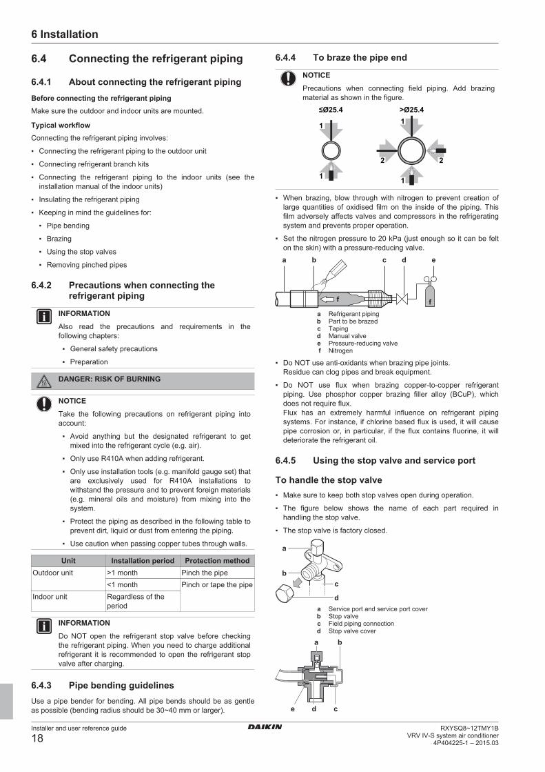
6.4.4 To braze the pipe end
NOTICE
Precautions when connecting field piping. Add brazingmaterial as shown in the figure.
1 1
11
2 2
≤Ø25.4 >Ø25.4
▪ When brazing, blow through with nitrogen to prevent creation oflarge quantities of oxidised film on the inside of the piping. Thisfilm adversely affects valves and compressors in the refrigeratingsystem and prevents proper operation.
▪ Set the nitrogen pressure to 20 kPa (just enough so it can be felton the skin) with a pressure-reducing valve.
a b c d e
ff
a Refrigerant pipingb Part to be brazedc Tapingd Manual valvee Pressure-reducing valvef Nitrogen
▪ Do NOT use anti-oxidants when brazing pipe joints.Residue can clog pipes and break equipment.
▪ Do NOT use flux when brazing copper-to-copper refrigerantpiping. Use phosphor copper brazing filler alloy (BCuP), whichdoes not require flux.Flux has an extremely harmful influence on refrigerant pipingsystems. For instance, if chlorine based flux is used, it will causepipe corrosion or, in particular, if the flux contains fluorine, it willdeteriorate the refrigerant oil.
6.4.5 Using the stop valve and service port
To handle the stop valve▪ Make sure to keep both stop valves open during operation.
▪ The figure below shows the name of each part required inhandling the stop valve.
▪ The stop valve is factory closed.
c
d
a
b
a Service port and service port coverb Stop valvec Field piping connectiond Stop valve cover
a b
cde
6 Installation
Installer and user reference guide
19RXYSQ8~12TMY1BVRV IV-S system air conditioner4P404225-1 – 2015.03
a Service portb Stop valve coverc Hexagon holed Shafte Seal
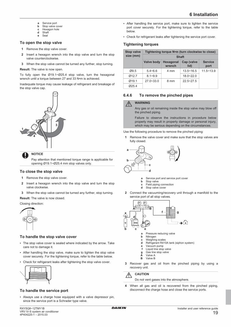
To open the stop valve1 Remove the stop valve cover.
2 Insert a hexagon wrench into the stop valve and turn the stopvalve counterclockwise.
3 When the stop valve cannot be turned any further, stop turning.
Result: The valve is now open.
To fully open the Ø19.1~Ø25.4 stop valve, turn the hexagonalwrench until a torque between 27 and 33 N•m is achieved.
Inadequate torque may cause leakage of refrigerant and breakage ofthe stop valve cap.
1
23
4
NOTICE
Pay attention that mentioned torque range is applicable foropening Ø19.1~Ø25.4 mm stop valves only.
To close the stop valve1 Remove the stop valve cover.
2 Insert a hexagon wrench into the stop valve and turn the stopvalve clockwise.
3 When the stop valve cannot be turned any further, stop turning.
Result: The valve is now closed.
Closing direction:
To handle the stop valve cover▪ The stop valve cover is sealed where indicated by the arrow. Take
care not to damage it.
▪ After handling the stop valve, make sure to tighten the stop valvecover securely. For the tightening torque, refer to the table below.
▪ Check for refrigerant leaks after tightening the stop valve cover.
To handle the service port▪ Always use a charge hose equipped with a valve depressor pin,
since the service port is a Schrader type valve.
▪ After handling the service port, make sure to tighten the serviceport cover securely. For the tightening torque, refer to the tablebelow.
▪ Check for refrigerant leaks after tightening the service port cover.
Tightening torques
Stop valvesize (mm)
Tightening torque N•m (turn clockwise to close)Shaft
Valve body Hexagonalwrench
Cap (valvelid)
Serviceport
Ø9.5 5.4~6.6 4 mm 13.5~16.5 11.5~13.9Ø12.7 8.1~9.9 18.0~22.0Ø19.1 27.0~33.0 8 mm 22.5~27.5Ø25.4
6.4.6 To remove the pinched pipes
WARNING
Any gas or oil remaining inside the stop valve may blow offthe pinched piping.
Failure to observe the instructions in procedure belowproperly may result in property damage or personal injury,which may be serious depending on the circumstances.
Use the following procedure to remove the pinched piping:
1 Remove the valve cover and make sure that the stop valves arefully closed.
c
d
a
b
a Service port and service port coverb Stop valvec Field piping connectiond Stop valve cover
2 Connect the vacuuming/recovery unit through a manifold to theservice port of all stop valves.
p< p>
R410AN2
b c e
a f gd
A B
a Pressure reducing valveb Nitrogenc Weighing scalesd Refrigerant R410A tank (siphon system)e Vacuum pumpf Liquid line stop valveg Gas line stop valveA Valve AB Valve B
3 Recover gas and oil from the pinched piping by using arecovery unit.
CAUTION
Do not vent gases into the atmosphere.
4 When all gas and oil is recovered from the pinched piping,disconnect the charge hose and close the service ports.
6 Installation
Installer and user reference guide
20RXYSQ8~12TMY1B
VRV IV-S system air conditioner4P404225-1 – 2015.03
5 Cut off the lower part of the gas and liquid stop valve pipesalong the black line. Use an appropriate tool (e.g. a pipe cutter,a pair of nippers).
WARNING
Never remove the pinched piping by brazing.
Any gas or oil remaining inside the stop valve may blow offthe pinched piping.
6 Wait until all oil is dripped out before continuing with theconnection of the field piping in case the recovery was notcomplete.
6.4.7 To connect the refrigerant piping to theoutdoor unit
NOTICE
Be sure that the field installed piping does not touch otherpipes, the bottom panel or side panel. Especially for thebottom and side connection, be sure to protect the pipingwith suitable insulation, to prevent it from coming intocontact with the casing.
1 Do the following:
▪ Remove the service cover. See "6.2.2 To open the outdoorunit" on page 16.
▪ Remove the piping intake plate (a) with screw (b).
ab
2 Choose a piping route (a, b, c or d).
8 HP
ab
c
d
10+12 HP
ab
c
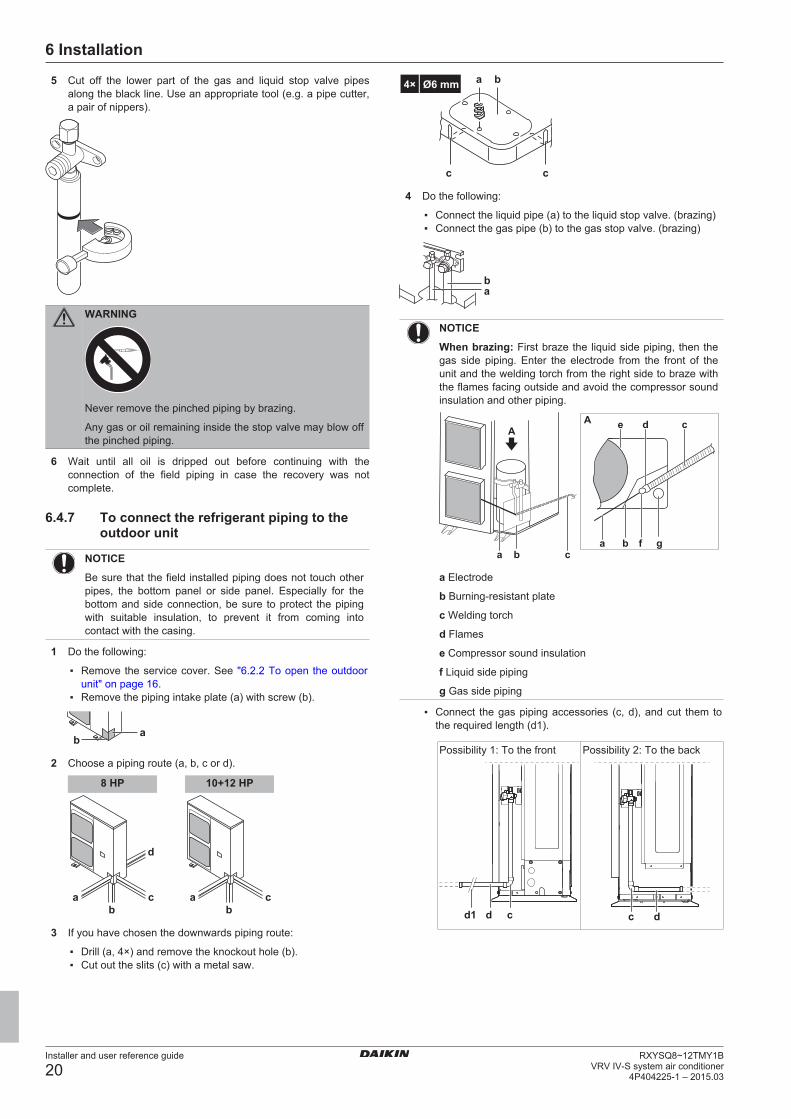
3 If you have chosen the downwards piping route:
▪ Drill (a, 4×) and remove the knockout hole (b).▪ Cut out the slits (c) with a metal saw.
cc
ba4× Ø6 mm
4 Do the following:
▪ Connect the liquid pipe (a) to the liquid stop valve. (brazing)▪ Connect the gas pipe (b) to the gas stop valve. (brazing)
ab
NOTICE
When brazing: First braze the liquid side piping, then thegas side piping. Enter the electrode from the front of theunit and the welding torch from the right side to braze withthe flames facing outside and avoid the compressor soundinsulation and other piping.
a b ca b f g
cdeAA
a Electrode
b Burning-resistant plate
c Welding torch
d Flames
e Compressor sound insulation
f Liquid side piping
g Gas side piping
▪ Connect the gas piping accessories (c, d), and cut them tothe required length (d1).
Possibility 1: To the front
cdd1
Possibility 2: To the back
dc
6 Installation
Installer and user reference guide
21RXYSQ8~12TMY1BVRV IV-S system air conditioner4P404225-1 – 2015.03
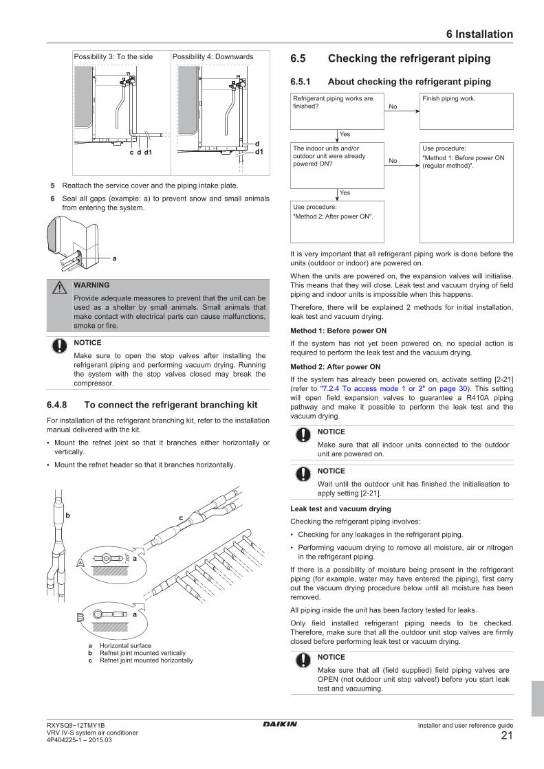
Possibility 3: To the side
c d d1
Possibility 4: Downwards
dd1
5 Reattach the service cover and the piping intake plate.
6 Seal all gaps (example: a) to prevent snow and small animalsfrom entering the system.
a
WARNING
Provide adequate measures to prevent that the unit can beused as a shelter by small animals. Small animals thatmake contact with electrical parts can cause malfunctions,smoke or fire.
NOTICE
Make sure to open the stop valves after installing therefrigerant piping and performing vacuum drying. Runningthe system with the stop valves closed may break thecompressor.
6.4.8 To connect the refrigerant branching kitFor installation of the refrigerant branching kit, refer to the installationmanual delivered with the kit.
▪ Mount the refnet joint so that it branches either horizontally orvertically.
▪ Mount the refnet header so that it branches horizontally.
A
B
±30° a
b c
a
a Horizontal surfaceb Refnet joint mounted verticallyc Refnet joint mounted horizontally
6.5 Checking the refrigerant piping
6.5.1 About checking the refrigerant pipingRefrigerant piping works are finished?
The indoor units and/or outdoor unit were already powered ON?
Use procedure:"Method 2: After power ON".
Finish piping work.
Use procedure:"Method 1: Before power ON (regular method)".
Yes
No
No
Yes
It is very important that all refrigerant piping work is done before theunits (outdoor or indoor) are powered on.
When the units are powered on, the expansion valves will initialise.This means that they will close. Leak test and vacuum drying of fieldpiping and indoor units is impossible when this happens.
Therefore, there will be explained 2 methods for initial installation,leak test and vacuum drying.
Method 1: Before power ONIf the system has not yet been powered on, no special action isrequired to perform the leak test and the vacuum drying.
Method 2: After power ONIf the system has already been powered on, activate setting [2‑21](refer to "7.2.4 To access mode 1 or 2" on page 30). This settingwill open field expansion valves to guarantee a R410A pipingpathway and make it possible to perform the leak test and thevacuum drying.
NOTICE
Make sure that all indoor units connected to the outdoorunit are powered on.
NOTICE
Wait until the outdoor unit has finished the initialisation toapply setting [2‑21].
Leak test and vacuum dryingChecking the refrigerant piping involves:
▪ Checking for any leakages in the refrigerant piping.
▪ Performing vacuum drying to remove all moisture, air or nitrogenin the refrigerant piping.
If there is a possibility of moisture being present in the refrigerantpiping (for example, water may have entered the piping), first carryout the vacuum drying procedure below until all moisture has beenremoved.
All piping inside the unit has been factory tested for leaks.
Only field installed refrigerant piping needs to be checked.Therefore, make sure that all the outdoor unit stop valves are firmlyclosed before performing leak test or vacuum drying.
NOTICE
Make sure that all (field supplied) field piping valves areOPEN (not outdoor unit stop valves!) before you start leaktest and vacuuming.
6 Installation
Installer and user reference guide
22RXYSQ8~12TMY1B
VRV IV-S system air conditioner4P404225-1 – 2015.03
For more information on the state of the valves, refer to"6.5.3 Checking refrigerant piping: Setup" on page 22.
6.5.2 Checking refrigerant piping: Generalguidelines
Connect the vacuum pump through a manifold to the service port ofall stop valves to increase efficiency (refer to "6.5.3 Checkingrefrigerant piping: Setup" on page 22).
NOTICE
Use a 2-stage vacuum pump with a non-return valve or asolenoid valve that can evacuate to a gauge pressure of–100.7 kPa (5 Torr absolute).
NOTICE
Make sure the pump oil does not flow oppositely into thesystem while the pump is not working.
NOTICE
Do not purge the air with refrigerants. Use a vacuum pumpto evacuate the installation.
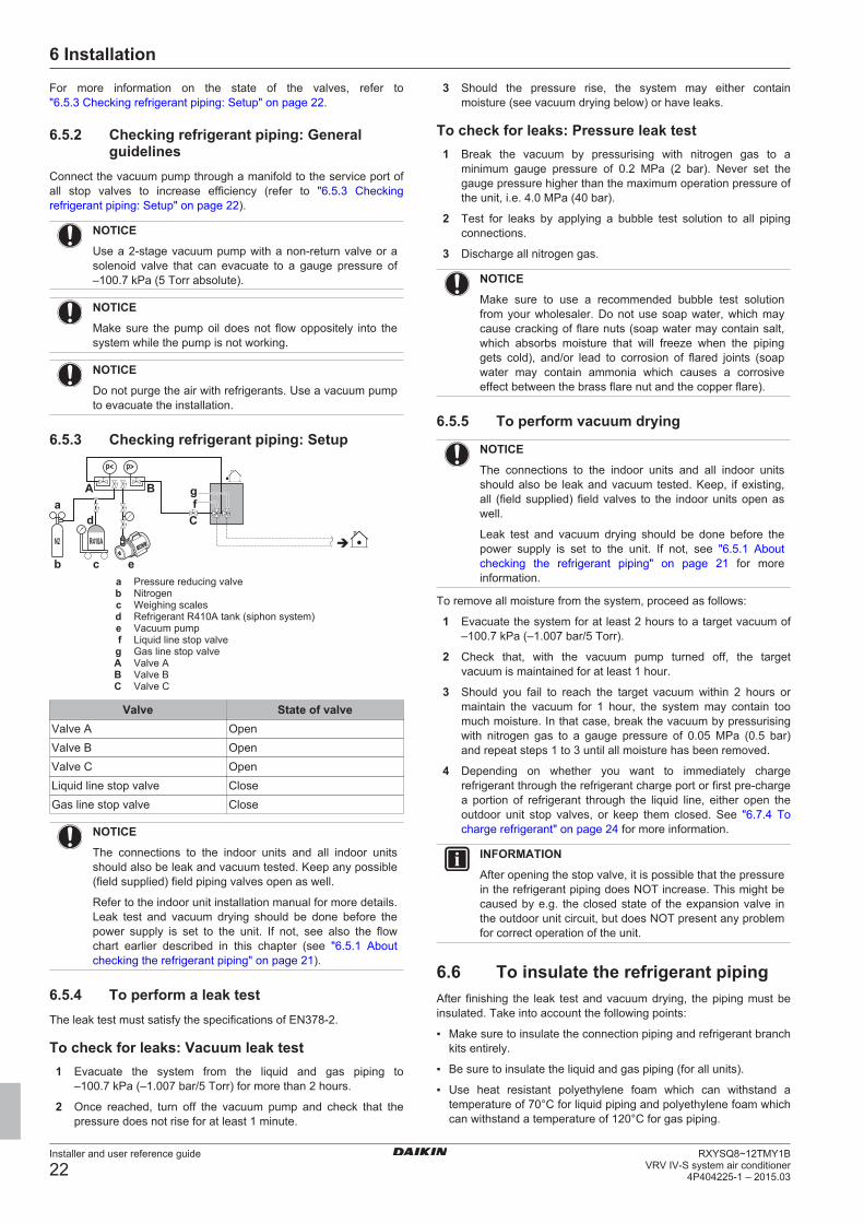
6.5.3 Checking refrigerant piping: Setupp< p>
R410AN2
C
b c e
agf
d
A B
a Pressure reducing valveb Nitrogenc Weighing scalesd Refrigerant R410A tank (siphon system)e Vacuum pumpf Liquid line stop valveg Gas line stop valveA Valve AB Valve BC Valve C
Valve State of valveValve A OpenValve B OpenValve C OpenLiquid line stop valve CloseGas line stop valve Close
NOTICE
The connections to the indoor units and all indoor unitsshould also be leak and vacuum tested. Keep any possible(field supplied) field piping valves open as well.
Refer to the indoor unit installation manual for more details.Leak test and vacuum drying should be done before thepower supply is set to the unit. If not, see also the flowchart earlier described in this chapter (see "6.5.1 Aboutchecking the refrigerant piping" on page 21).
6.5.4 To perform a leak testThe leak test must satisfy the specifications of EN378‑2.
To check for leaks: Vacuum leak test1 Evacuate the system from the liquid and gas piping to
–100.7 kPa (–1.007 bar/5 Torr) for more than 2 hours.
2 Once reached, turn off the vacuum pump and check that thepressure does not rise for at least 1 minute.
3 Should the pressure rise, the system may either containmoisture (see vacuum drying below) or have leaks.
To check for leaks: Pressure leak test1 Break the vacuum by pressurising with nitrogen gas to a
minimum gauge pressure of 0.2 MPa (2 bar). Never set thegauge pressure higher than the maximum operation pressure ofthe unit, i.e. 4.0 MPa (40 bar).
2 Test for leaks by applying a bubble test solution to all pipingconnections.
3 Discharge all nitrogen gas.
NOTICE
Make sure to use a recommended bubble test solutionfrom your wholesaler. Do not use soap water, which maycause cracking of flare nuts (soap water may contain salt,which absorbs moisture that will freeze when the pipinggets cold), and/or lead to corrosion of flared joints (soapwater may contain ammonia which causes a corrosiveeffect between the brass flare nut and the copper flare).
6.5.5 To perform vacuum drying
NOTICE
The connections to the indoor units and all indoor unitsshould also be leak and vacuum tested. Keep, if existing,all (field supplied) field valves to the indoor units open aswell.
Leak test and vacuum drying should be done before thepower supply is set to the unit. If not, see "6.5.1 Aboutchecking the refrigerant piping" on page 21 for moreinformation.
To remove all moisture from the system, proceed as follows:
1 Evacuate the system for at least 2 hours to a target vacuum of–100.7 kPa (–1.007 bar/5 Torr).
2 Check that, with the vacuum pump turned off, the targetvacuum is maintained for at least 1 hour.
3 Should you fail to reach the target vacuum within 2 hours ormaintain the vacuum for 1 hour, the system may contain toomuch moisture. In that case, break the vacuum by pressurisingwith nitrogen gas to a gauge pressure of 0.05 MPa (0.5 bar)and repeat steps 1 to 3 until all moisture has been removed.
4 Depending on whether you want to immediately chargerefrigerant through the refrigerant charge port or first pre-chargea portion of refrigerant through the liquid line, either open theoutdoor unit stop valves, or keep them closed. See "6.7.4 Tocharge refrigerant" on page 24 for more information.
INFORMATION
After opening the stop valve, it is possible that the pressurein the refrigerant piping does NOT increase. This might becaused by e.g. the closed state of the expansion valve inthe outdoor unit circuit, but does NOT present any problemfor correct operation of the unit.
6.6 To insulate the refrigerant pipingAfter finishing the leak test and vacuum drying, the piping must beinsulated. Take into account the following points:
▪ Make sure to insulate the connection piping and refrigerant branchkits entirely.
▪ Be sure to insulate the liquid and gas piping (for all units).
▪ Use heat resistant polyethylene foam which can withstand atemperature of 70°C for liquid piping and polyethylene foam whichcan withstand a temperature of 120°C for gas piping.
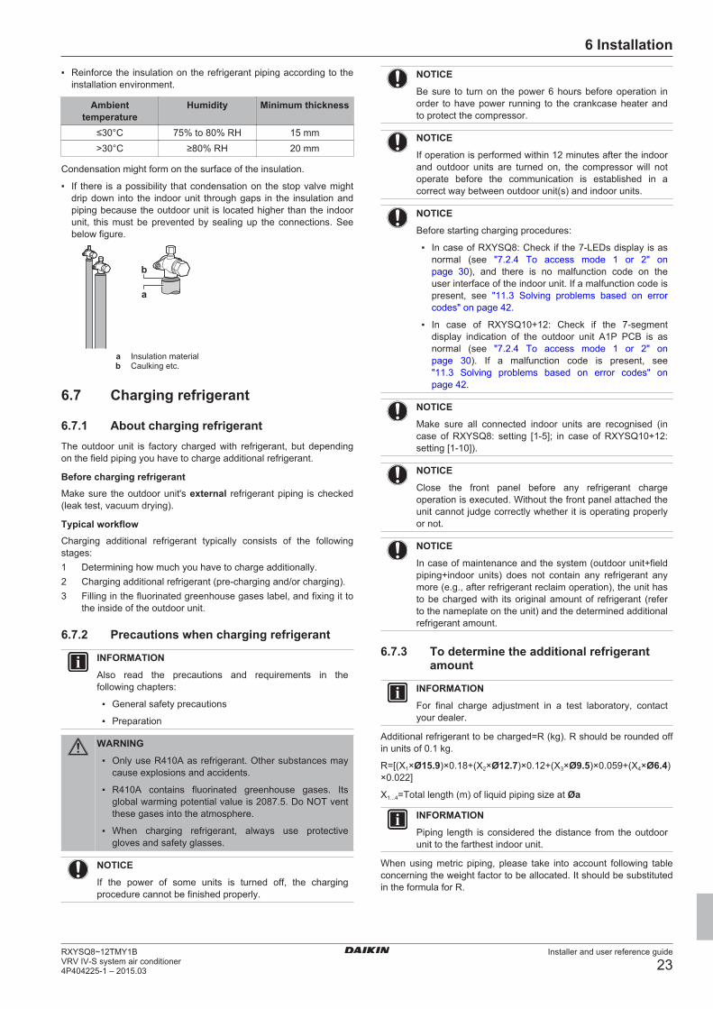
6 Installation
Installer and user reference guide
23RXYSQ8~12TMY1BVRV IV-S system air conditioner4P404225-1 – 2015.03
▪ Reinforce the insulation on the refrigerant piping according to theinstallation environment.
Ambienttemperature
Humidity Minimum thickness
≤30°C 75% to 80% RH 15 mm>30°C ≥80% RH 20 mm
Condensation might form on the surface of the insulation.
▪ If there is a possibility that condensation on the stop valve mightdrip down into the indoor unit through gaps in the insulation andpiping because the outdoor unit is located higher than the indoorunit, this must be prevented by sealing up the connections. Seebelow figure.
b
a
a Insulation materialb Caulking etc.
6.7 Charging refrigerant
6.7.1 About charging refrigerantThe outdoor unit is factory charged with refrigerant, but dependingon the field piping you have to charge additional refrigerant.
Before charging refrigerantMake sure the outdoor unit's external refrigerant piping is checked(leak test, vacuum drying).
Typical workflowCharging additional refrigerant typically consists of the followingstages:1 Determining how much you have to charge additionally.2 Charging additional refrigerant (pre-charging and/or charging).3 Filling in the fluorinated greenhouse gases label, and fixing it to
the inside of the outdoor unit.
6.7.2 Precautions when charging refrigerant
INFORMATION
Also read the precautions and requirements in thefollowing chapters:
▪ General safety precautions
▪ Preparation
WARNING
▪ Only use R410A as refrigerant. Other substances maycause explosions and accidents.
▪ R410A contains fluorinated greenhouse gases. Itsglobal warming potential value is 2087.5. Do NOT ventthese gases into the atmosphere.
▪ When charging refrigerant, always use protectivegloves and safety glasses.
NOTICE
If the power of some units is turned off, the chargingprocedure cannot be finished properly.
NOTICE
Be sure to turn on the power 6 hours before operation inorder to have power running to the crankcase heater andto protect the compressor.
NOTICE
If operation is performed within 12 minutes after the indoorand outdoor units are turned on, the compressor will notoperate before the communication is established in acorrect way between outdoor unit(s) and indoor units.
NOTICE
Before starting charging procedures:
▪ In case of RXYSQ8: Check if the 7‑LEDs display is asnormal (see "7.2.4 To access mode 1 or 2" onpage 30), and there is no malfunction code on theuser interface of the indoor unit. If a malfunction code ispresent, see "11.3 Solving problems based on errorcodes" on page 42.
▪ In case of RXYSQ10+12: Check if the 7‑segmentdisplay indication of the outdoor unit A1P PCB is asnormal (see "7.2.4 To access mode 1 or 2" onpage 30). If a malfunction code is present, see"11.3 Solving problems based on error codes" onpage 42.
NOTICE
Make sure all connected indoor units are recognised (incase of RXYSQ8: setting [1‑5]; in case of RXYSQ10+12:setting [1‑10]).
NOTICE
Close the front panel before any refrigerant chargeoperation is executed. Without the front panel attached theunit cannot judge correctly whether it is operating properlyor not.
NOTICE
In case of maintenance and the system (outdoor unit+fieldpiping+indoor units) does not contain any refrigerant anymore (e.g., after refrigerant reclaim operation), the unit hasto be charged with its original amount of refrigerant (referto the nameplate on the unit) and the determined additionalrefrigerant amount.
6.7.3 To determine the additional refrigerantamount
INFORMATION
For final charge adjustment in a test laboratory, contactyour dealer.
Additional refrigerant to be charged=R (kg). R should be rounded offin units of 0.1 kg.
R=[(X1×Ø15.9)×0.18+(X2×Ø12.7)×0.12+(X3×Ø9.5)×0.059+(X4×Ø6.4)×0.022]
X1...4=Total length (m) of liquid piping size at Øa
INFORMATION
Piping length is considered the distance from the outdoorunit to the farthest indoor unit.
When using metric piping, please take into account following tableconcerning the weight factor to be allocated. It should be substitutedin the formula for R.
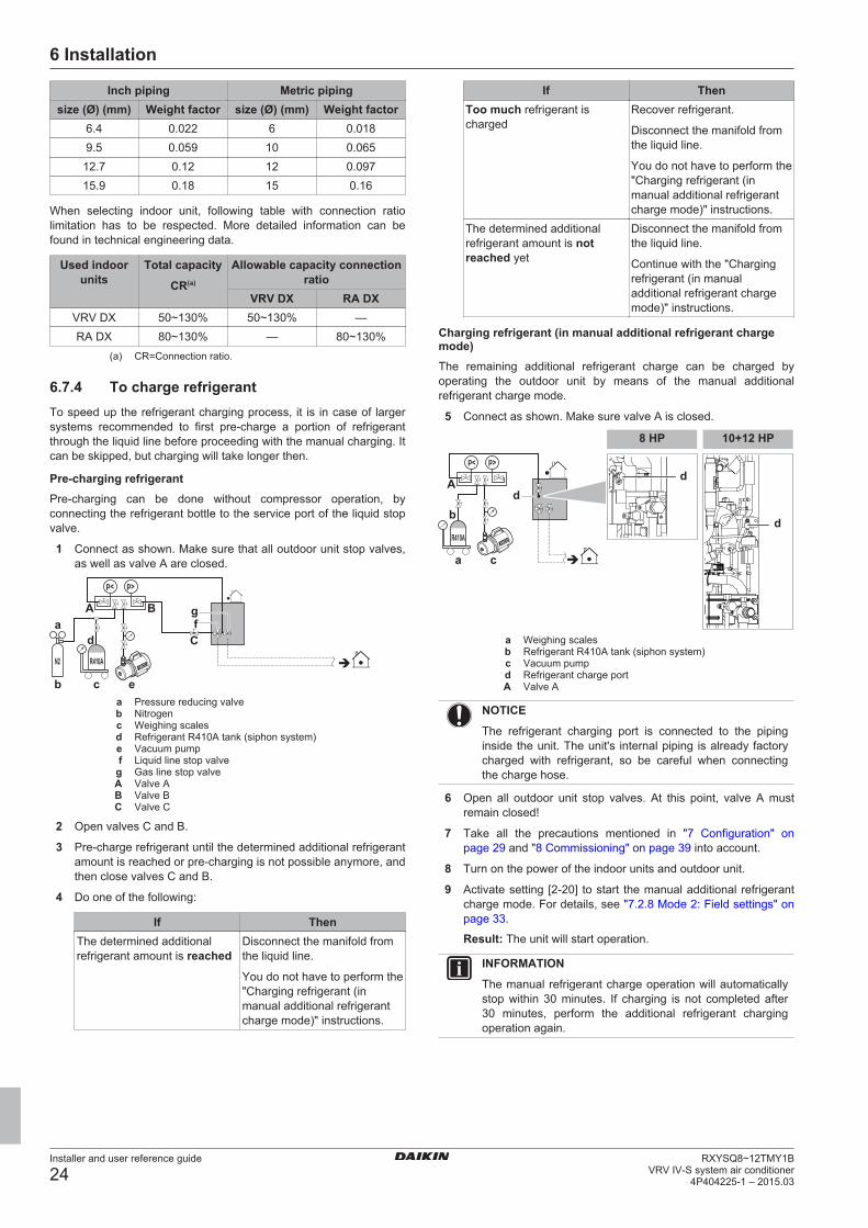
6 Installation
Installer and user reference guide
24RXYSQ8~12TMY1B
VRV IV-S system air conditioner4P404225-1 – 2015.03
Inch piping Metric pipingsize (Ø) (mm) Weight factor size (Ø) (mm) Weight factor
6.4 0.022 6 0.0189.5 0.059 10 0.065
12.7 0.12 12 0.09715.9 0.18 15 0.16
When selecting indoor unit, following table with connection ratiolimitation has to be respected. More detailed information can befound in technical engineering data.
Used indoorunits
Total capacity
CR(a)
Allowable capacity connectionratio
VRV DX RA DXVRV DX 50~130% 50~130% —RA DX 80~130% — 80~130%
(a) CR=Connection ratio.
6.7.4 To charge refrigerantTo speed up the refrigerant charging process, it is in case of largersystems recommended to first pre-charge a portion of refrigerantthrough the liquid line before proceeding with the manual charging. Itcan be skipped, but charging will take longer then.
Pre-charging refrigerantPre-charging can be done without compressor operation, byconnecting the refrigerant bottle to the service port of the liquid stopvalve.
1 Connect as shown. Make sure that all outdoor unit stop valves,as well as valve A are closed.
p< p>
R410AN2
C
b c e
agf
d
A B
a Pressure reducing valveb Nitrogenc Weighing scalesd Refrigerant R410A tank (siphon system)e Vacuum pumpf Liquid line stop valveg Gas line stop valveA Valve AB Valve BC Valve C
2 Open valves C and B.
3 Pre‑charge refrigerant until the determined additional refrigerantamount is reached or pre‑charging is not possible anymore, andthen close valves C and B.
4 Do one of the following:
If ThenThe determined additionalrefrigerant amount is reached
Disconnect the manifold fromthe liquid line.
You do not have to perform the"Charging refrigerant (inmanual additional refrigerantcharge mode)" instructions.
If ThenToo much refrigerant ischarged
Recover refrigerant.
Disconnect the manifold fromthe liquid line.
You do not have to perform the"Charging refrigerant (inmanual additional refrigerantcharge mode)" instructions.
The determined additionalrefrigerant amount is notreached yet
Disconnect the manifold fromthe liquid line.
Continue with the "Chargingrefrigerant (in manualadditional refrigerant chargemode)" instructions.
Charging refrigerant (in manual additional refrigerant chargemode)The remaining additional refrigerant charge can be charged byoperating the outdoor unit by means of the manual additionalrefrigerant charge mode.
5 Connect as shown. Make sure valve A is closed.
p< p>
R410A
a c
db
Ad
d
8 HP 10+12 HP
a Weighing scalesb Refrigerant R410A tank (siphon system)c Vacuum pumpd Refrigerant charge portA Valve A
NOTICE
The refrigerant charging port is connected to the pipinginside the unit. The unit's internal piping is already factorycharged with refrigerant, so be careful when connectingthe charge hose.
6 Open all outdoor unit stop valves. At this point, valve A mustremain closed!
7 Take all the precautions mentioned in "7 Configuration" onpage 29 and "8 Commissioning" on page 39 into account.
8 Turn on the power of the indoor units and outdoor unit.
9 Activate setting [2‑20] to start the manual additional refrigerantcharge mode. For details, see "7.2.8 Mode 2: Field settings" onpage 33.
Result: The unit will start operation.
INFORMATION
The manual refrigerant charge operation will automaticallystop within 30 minutes. If charging is not completed after30 minutes, perform the additional refrigerant chargingoperation again.
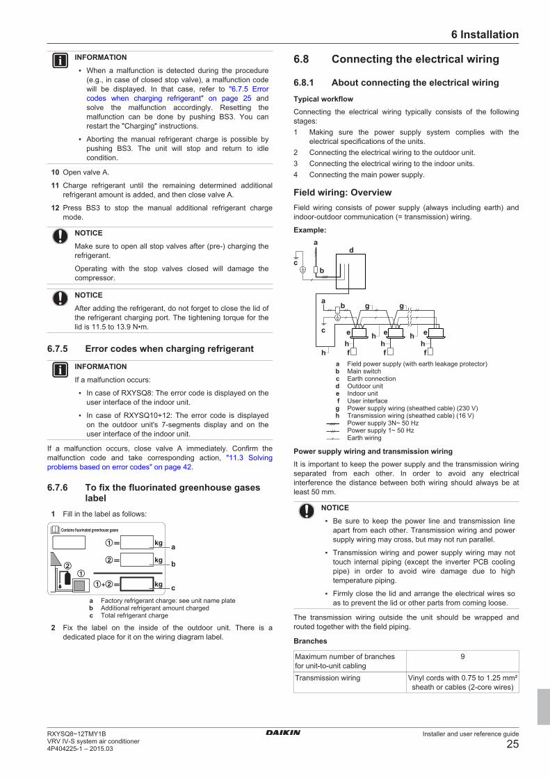
6 Installation
Installer and user reference guide
25RXYSQ8~12TMY1BVRV IV-S system air conditioner4P404225-1 – 2015.03
INFORMATION
▪ When a malfunction is detected during the procedure(e.g., in case of closed stop valve), a malfunction codewill be displayed. In that case, refer to "6.7.5 Errorcodes when charging refrigerant" on page 25 andsolve the malfunction accordingly. Resetting themalfunction can be done by pushing BS3. You canrestart the "Charging" instructions.
▪ Aborting the manual refrigerant charge is possible bypushing BS3. The unit will stop and return to idlecondition.
10 Open valve A.
11 Charge refrigerant until the remaining determined additionalrefrigerant amount is added, and then close valve A.
12 Press BS3 to stop the manual additional refrigerant chargemode.
NOTICE
Make sure to open all stop valves after (pre-) charging therefrigerant.
Operating with the stop valves closed will damage thecompressor.
NOTICE
After adding the refrigerant, do not forget to close the lid ofthe refrigerant charging port. The tightening torque for thelid is 11.5 to 13.9 N•m.
6.7.5 Error codes when charging refrigerant
INFORMATION
If a malfunction occurs:
▪ In case of RXYSQ8: The error code is displayed on theuser interface of the indoor unit.
▪ In case of RXYSQ10+12: The error code is displayedon the outdoor unit's 7‑segments display and on theuser interface of the indoor unit.
If a malfunction occurs, close valve A immediately. Confirm themalfunction code and take corresponding action, "11.3 Solvingproblems based on error codes" on page 42.
6.7.6 To fix the fluorinated greenhouse gaseslabel
1 Fill in the label as follows:
c
b
a
a Factory refrigerant charge: see unit name plateb Additional refrigerant amount chargedc Total refrigerant charge
2 Fix the label on the inside of the outdoor unit. There is adedicated place for it on the wiring diagram label.
6.8 Connecting the electrical wiring
6.8.1 About connecting the electrical wiringTypical workflowConnecting the electrical wiring typically consists of the followingstages:1 Making sure the power supply system complies with the
electrical specifications of the units.2 Connecting the electrical wiring to the outdoor unit.3 Connecting the electrical wiring to the indoor units.4 Connecting the main power supply.
Field wiring: OverviewField wiring consists of power supply (always including earth) andindoor-outdoor communication (= transmission) wiring.
Example:a
d
bc
b g g
c
fffh
eee
a
h h hh h
a Field power supply (with earth leakage protector)b Main switchc Earth connectiond Outdoor unite Indoor unitf User interfaceg Power supply wiring (sheathed cable) (230 V)h Transmission wiring (sheathed cable) (16 V)
Power supply 3N~ 50 HzPower supply 1~ 50 HzEarth wiring
Power supply wiring and transmission wiringIt is important to keep the power supply and the transmission wiringseparated from each other. In order to avoid any electricalinterference the distance between both wiring should always be atleast 50 mm.
NOTICE
▪ Be sure to keep the power line and transmission lineapart from each other. Transmission wiring and powersupply wiring may cross, but may not run parallel.
▪ Transmission wiring and power supply wiring may nottouch internal piping (except the inverter PCB coolingpipe) in order to avoid wire damage due to hightemperature piping.
▪ Firmly close the lid and arrange the electrical wires soas to prevent the lid or other parts from coming loose.
The transmission wiring outside the unit should be wrapped androuted together with the field piping.
Branches
Maximum number of branchesfor unit-to-unit cabling
9
Transmission wiring Vinyl cords with 0.75 to 1.25 mm²sheath or cables (2‑core wires)
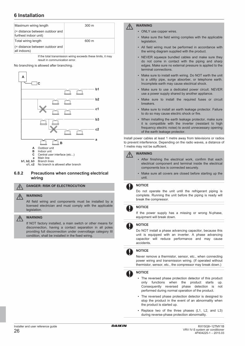
6 Installation
Installer and user reference guide
26RXYSQ8~12TMY1B
VRV IV-S system air conditioner4P404225-1 – 2015.03
Maximum wiring length
(= distance between outdoor andfurthest indoor unit)
300 m
Total wiring length
(= distance between outdoor andall indoors)
600 m
If the total transmission wiring exceeds these limits, it mayresult in communication error.
No branching is allowed after branching.
A
B
C
b2
b3
c1
c2
b1
a
A Outdoor unitB Indoor unitC Central user interface (etc...)a Main line
b1, b2, b3 Branch linesc1, c2 No branch is allowed after branch
6.8.2 Precautions when connecting electricalwiring
DANGER: RISK OF ELECTROCUTION
WARNING
All field wiring and components must be installed by alicensed electrician and must comply with the applicablelegislation.
WARNING
If NOT factory installed, a main switch or other means fordisconnection, having a contact separation in all polesproviding full disconnection under overvoltage category IIIcondition, shall be installed in the fixed wiring.
WARNING
▪ ONLY use copper wires.
▪ Make sure the field wiring complies with the applicablelegislation.
▪ All field wiring must be performed in accordance withthe wiring diagram supplied with the product.
▪ NEVER squeeze bundled cables and make sure theydo not come in contact with the piping and sharpedges. Make sure no external pressure is applied to theterminal connections.
▪ Make sure to install earth wiring. Do NOT earth the unitto a utility pipe, surge absorber, or telephone earth.Incomplete earth may cause electrical shock.
▪ Make sure to use a dedicated power circuit. NEVERuse a power supply shared by another appliance.
▪ Make sure to install the required fuses or circuitbreakers.
▪ Make sure to install an earth leakage protector. Failureto do so may cause electric shock or fire.
▪ When installing the earth leakage protector, make sureit is compatible with the inverter (resistant to highfrequency electric noise) to avoid unnecessary openingof the earth leakage protector.
Install power cables at least 1 metre away from televisions or radiosto prevent interference. Depending on the radio waves, a distance of1 metre may not be sufficient.
WARNING
▪ After finishing the electrical work, confirm that eachelectrical component and terminal inside the electricalcomponents box is connected securely.
▪ Make sure all covers are closed before starting up theunit.
NOTICE
Do not operate the unit until the refrigerant piping iscomplete. Running the unit before the piping is ready willbreak the compressor.
NOTICE
If the power supply has a missing or wrong N-phase,equipment will break down.
NOTICE
Do NOT install a phase advancing capacitor, because thisunit is equipped with an inverter. A phase advancingcapacitor will reduce performance and may causeaccidents.
NOTICE
Never remove a thermistor, sensor, etc., when connectingpower wiring and transmission wiring. (If operated withoutthermistor, sensor, etc., the compressor may break down.)
NOTICE
▪ The reversed phase protection detector of this productonly functions when the product starts up.Consequently reversed phase detection is notperformed during normal operation of the product.
▪ The reversed phase protection detector is designed tostop the product in the event of an abnormality whenthe product is started up.
▪ Replace two of the three phases (L1, L2, and L3)during reverse-phase protection abnormality.
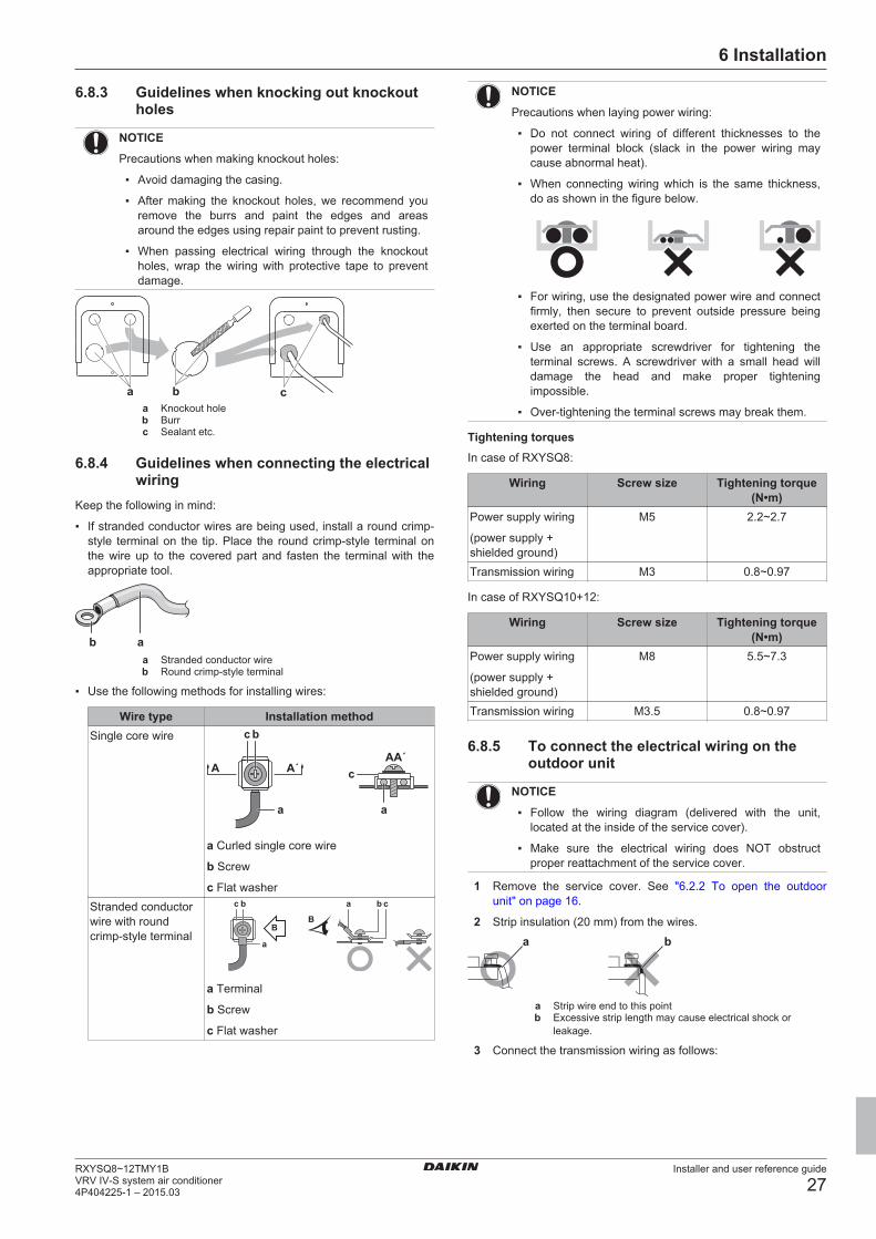
6 Installation
Installer and user reference guide
27RXYSQ8~12TMY1BVRV IV-S system air conditioner4P404225-1 – 2015.03
6.8.3 Guidelines when knocking out knockoutholes
NOTICE
Precautions when making knockout holes:
▪ Avoid damaging the casing.
▪ After making the knockout holes, we recommend youremove the burrs and paint the edges and areasaround the edges using repair paint to prevent rusting.
▪ When passing electrical wiring through the knockoutholes, wrap the wiring with protective tape to preventdamage.
b caa Knockout holeb Burrc Sealant etc.
6.8.4 Guidelines when connecting the electricalwiring
Keep the following in mind:
▪ If stranded conductor wires are being used, install a round crimp-style terminal on the tip. Place the round crimp-style terminal onthe wire up to the covered part and fasten the terminal with theappropriate tool.
b aa Stranded conductor wireb Round crimp-style terminal
▪ Use the following methods for installing wires:
Wire type Installation methodSingle core wire c b
c
aa
AAA´
A´
a Curled single core wire
b Screw
c Flat washerStranded conductorwire with roundcrimp-style terminal
c b ba c
a
BB
a Terminal
b Screw
c Flat washer
NOTICE
Precautions when laying power wiring:
▪ Do not connect wiring of different thicknesses to thepower terminal block (slack in the power wiring maycause abnormal heat).
▪ When connecting wiring which is the same thickness,do as shown in the figure below.
▪ For wiring, use the designated power wire and connectfirmly, then secure to prevent outside pressure beingexerted on the terminal board.
▪ Use an appropriate screwdriver for tightening theterminal screws. A screwdriver with a small head willdamage the head and make proper tighteningimpossible.
▪ Over-tightening the terminal screws may break them.
Tightening torquesIn case of RXYSQ8:
Wiring Screw size Tightening torque(N•m)
Power supply wiring
(power supply +shielded ground)
M5 2.2~2.7
Transmission wiring M3 0.8~0.97
In case of RXYSQ10+12:
Wiring Screw size Tightening torque(N•m)
Power supply wiring
(power supply +shielded ground)
M8 5.5~7.3
Transmission wiring M3.5 0.8~0.97
6.8.5 To connect the electrical wiring on theoutdoor unit
NOTICE
▪ Follow the wiring diagram (delivered with the unit,located at the inside of the service cover).
▪ Make sure the electrical wiring does NOT obstructproper reattachment of the service cover.
1 Remove the service cover. See "6.2.2 To open the outdoorunit" on page 16.
2 Strip insulation (20 mm) from the wires.
a b
a Strip wire end to this pointb Excessive strip length may cause electrical shock or
leakage.
3 Connect the transmission wiring as follows:
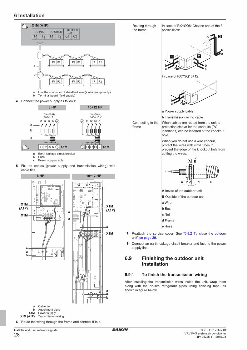
6 Installation
Installer and user reference guide
28RXYSQ8~12TMY1B
VRV IV-S system air conditioner4P404225-1 – 2015.03
F1 F2 F1 F2 F1 F2
F1 F2 F1 F2 F1 F2
a
b
X1M (A1P)
F1 Q2F2F1 Q1F2
TO MULTI UNITTO OUT/DTO IN/D
a Use the conductor of sheathed wire (2 wire) (no polarity)b Terminal board (field supply)
4 Connect the power supply as follows:
3N~50 Hz380-415 V
L1 L2 L3
L1 L2 L3
N
8 HP 10+12 HP
3N~50 Hz380-415 V
L1 L2 L3
L1 L2 L3
NX1M X1M
ab
c
a Earth leakage circuit breakerb Fusec Power supply cable
5 Fix the cables (power supply and transmission wiring) withcable ties.
X1M(A1P)
X1M
aa
b
X1M
X1M(A1P)
a
a
baa
a
8 HP 10+12 HP
a Cable tieb Attachment plate
X1M Power supplyX1M (A1P) Transmission wiring
6 Route the wiring through the frame and connect it to it.
Routing throughthe frame
In case of RXYSQ8: Choose one of the 3possibilities:
ab
ab
ab
2
3
1
In case of RXYSQ10+12:
ab
a Power supply cable
b Transmission wiring cableConnecting to theframe
When cables are routed from the unit, aprotection sleeve for the conduits (PGinsertions) can be inserted at the knockouthole.
When you do not use a wire conduit,protect the wires with vinyl tubes toprevent the edge of the knockout hole fromcutting the wires.
a b c d e
A B
A Inside of the outdoor unit
B Outside of the outdoor unit
a Wire
b Bush
c Nut
d Frame
e Hose
7 Reattach the service cover. See "6.9.2 To close the outdoorunit" on page 29.
8 Connect an earth leakage circuit breaker and fuse to the powersupply line.
6.9 Finishing the outdoor unitinstallation
6.9.1 To finish the transmission wiringAfter installing the transmission wires inside the unit, wrap themalong with the on-site refrigerant pipes using finishing tape, asshown in figure below.
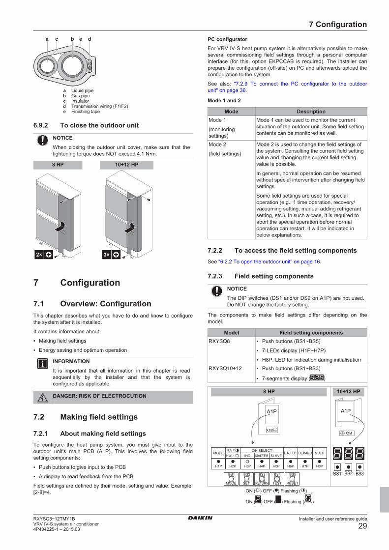
7 Configuration
Installer and user reference guide
29RXYSQ8~12TMY1BVRV IV-S system air conditioner4P404225-1 – 2015.03
a bc de
a Liquid pipeb Gas pipec Insulatord Transmission wiring (F1/F2)e Finishing tape
6.9.2 To close the outdoor unit
NOTICE
When closing the outdoor unit cover, make sure that thetightening torque does NOT exceed 4.1 N•m.
2× 3×
8 HP 10+12 HP
7 Configuration
7.1 Overview: ConfigurationThis chapter describes what you have to do and know to configurethe system after it is installed.
It contains information about:
▪ Making field settings
▪ Energy saving and optimum operation
INFORMATION
It is important that all information in this chapter is readsequentially by the installer and that the system isconfigured as applicable.
DANGER: RISK OF ELECTROCUTION
7.2 Making field settings
7.2.1 About making field settingsTo configure the heat pump system, you must give input to theoutdoor unit's main PCB (A1P). This involves the following fieldsetting components:
▪ Push buttons to give input to the PCB
▪ A display to read feedback from the PCB
Field settings are defined by their mode, setting and value. Example:[2‑8]=4.
PC configuratorFor VRV IV-S heat pump system it is alternatively possible to makeseveral commissioning field settings through a personal computerinterface (for this, option EKPCCAB is required). The installer canprepare the configuration (off-site) on PC and afterwards upload theconfiguration to the system.
See also: "7.2.9 To connect the PC configurator to the outdoorunit" on page 36.
Mode 1 and 2
Mode DescriptionMode 1
(monitoringsettings)
Mode 1 can be used to monitor the currentsituation of the outdoor unit. Some field settingcontents can be monitored as well.
Mode 2
(field settings)
Mode 2 is used to change the field settings ofthe system. Consulting the current field settingvalue and changing the current field settingvalue is possible.
In general, normal operation can be resumedwithout special intervention after changing fieldsettings.
Some field settings are used for specialoperation (e.g., 1 time operation, recovery/vacuuming setting, manual adding refrigerantsetting, etc.). In such a case, it is required toabort the special operation before normaloperation can restart. It will be indicated inbelow explanations.
7.2.2 To access the field setting componentsSee "6.2.2 To open the outdoor unit" on page 16.
7.2.3 Field setting components
NOTICE
The DIP switches (DS1 and/or DS2 on A1P) are not used.Do NOT change the factory setting.
The components to make field settings differ depending on themodel.
Model Field setting componentsRXYSQ8 ▪ Push buttons (BS1~BS5)
▪ 7‑LEDs display (H1P~H7P)
▪ H8P: LED for indication during initialisationRXYSQ10+12 ▪ Push buttons (BS1~BS3)
▪ 7‑segments display ( )
X1M
A1P
8 HP
BS2
SET
BS1
MODE
BS3
RETURN
BS4
TEST
BS5
RESET
H1P H2P H3P H4P H5P H6P H7P
MODETEST:
L.N.O.P. DEMANDC/H SELECT
HWL: IND MASTER SLAVE
10+12 HP
A1P
X1M
BS1 BS2 BS3H8P
MULTI
ON ( ) OFF ( ) Flashing ( )
ON ( ) OFF ( ) Flashing ( )
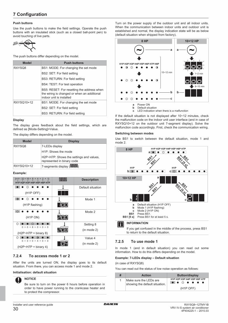
7 Configuration
Installer and user reference guide
30RXYSQ8~12TMY1B
VRV IV-S system air conditioner4P404225-1 – 2015.03
Push buttonsUse the push buttons to make the field settings. Operate the pushbuttons with an insulated stick (such as a closed ball-point pen) toavoid touching of live parts.
The push buttons differ depending on the model.
Model Push buttonsRXYSQ8 BS1: MODE: For changing the set mode
BS2: SET: For field setting
BS3: RETURN: For field setting
BS4: TEST: For test operation
BS5: RESET: For resetting the address whenthe wiring is changed or when an additionalindoor unit is installed
RXYSQ10+12 BS1: MODE: For changing the set mode
BS2: SET: For field setting
BS3: RETURN: For field setting
DisplayThe display gives feedback about the field settings, which aredefined as [Mode-Setting]=Value.
The display differs depending on the model.
Model DisplayRXYSQ8 7‑LEDs display
H1P: Shows the mode
H2P~H7P: Shows the settings and values,represented in binary code
RXYSQ10+12 7‑segments display ( )
Example:
H1P H2P H3P H4P H5P H6P H7P
- + + + + +[H1P 32 16 8 4 2 1] Description
(H1P OFF)
Default situation
(H1P flashing)
Mode 1
(H1P ON)
Mode 2
+ + + + +0 0 8 0 0 0
(H2P~H7P = binary 8)
Setting 8
(in mode 2)
+ + + + +0 0 0 4 0 0
(H2P~H7P = binary 4)
Value 4
(in mode 2)
7.2.4 To access mode 1 or 2After the units are turned ON, the display goes to its defaultsituation. From there, you can access mode 1 and mode 2.
Initialisation: default situation
NOTICE
Be sure to turn on the power 6 hours before operation inorder to have power running to the crankcase heater andto protect the compressor.
Turn on the power supply of the outdoor unit and all indoor units.When the communication between indoor units and outdoor unit isestablished and normal, the display indication state will be as below(default situation when shipped from factory).
1~2 min
8~10 min
10~12 min
8 HP 10+12 HP
b
c
b
a a
a Power ONb Default situationc LED indication when there is a malfunction
If the default situation is not displayed after 10~12 minutes, checkthe malfunction code on the indoor unit user interface (and in case ofRXYSQ10+12 on the outdoor unit 7‑segment display). Solve themalfunction code accordingly. First, check the communication wiring.
Switching between modesUse BS1 to switch between the default situation, mode 1 andmode 2.
BS1 [5 s]BS1BS1 BS1
a
cb
BS1 [5 s]BS1BS1 BS1
a
b c
8 HP
10+12 HP
a Default situation (H1P OFF)b Mode 1 (H1P flashing)c Mode 2 (H1P ON)
BS1 Press BS1.BS1 [5 s] Press BS1 for at least 5 s.
INFORMATION
If you get confused in the middle of the process, press BS1to return to the default situation.
7.2.5 To use mode 1In mode 1 (and in default situation) you can read out someinformation. How to do this differs depending on the model.
Example: 7‑LEDs display – Default situation(in case of RXYSQ8)
You can read out the status of low noise operation as follows:
# Action Button/display1 Make sure the LEDs are
showing the default situation.(H1P OFF)
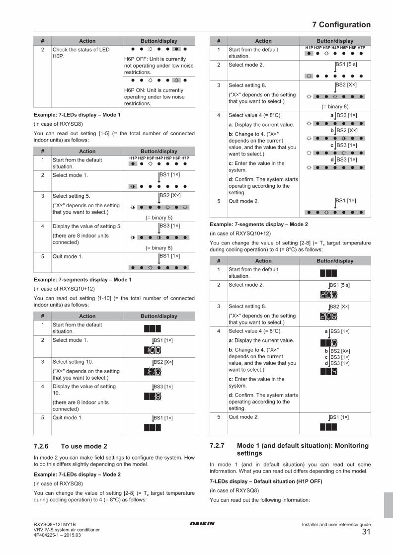
7 Configuration
Installer and user reference guide
31RXYSQ8~12TMY1BVRV IV-S system air conditioner4P404225-1 – 2015.03
# Action Button/display2 Check the status of LED
H6P. H6P OFF: Unit is currentlynot operating under low noiserestrictions.
H6P ON: Unit is currentlyoperating under low noiserestrictions.
Example: 7‑LEDs display – Mode 1(in case of RXYSQ8)
You can read out setting [1‑5] (= the total number of connectedindoor units) as follows:
# Action Button/display1 Start from the default
situation.2 Select mode 1. BS1 [1×]
3 Select setting 5.
("X×" depends on the settingthat you want to select.)
BS2 [X×]
(= binary 5)4 Display the value of setting 5.
(there are 8 indoor unitsconnected)
BS3 [1×]
(= binary 8)5 Quit mode 1. BS1 [1×]
Example: 7‑segments display – Mode 1(in case of RXYSQ10+12)
You can read out setting [1‑10] (= the total number of connectedindoor units) as follows:
# Action Button/display1 Start from the default
situation.2 Select mode 1. BS1 [1×]
3 Select setting 10.
("X×" depends on the settingthat you want to select.)
BS2 [X×]
4 Display the value of setting10.
(there are 8 indoor unitsconnected)
BS3 [1×]
5 Quit mode 1. BS1 [1×]
7.2.6 To use mode 2In mode 2 you can make field settings to configure the system. Howto do this differs slightly depending on the model.
Example: 7‑LEDs display – Mode 2(in case of RXYSQ8)
You can change the value of setting [2‑8] (= Te target temperatureduring cooling operation) to 4 (= 8°C) as follows:
# Action Button/display1 Start from the default
situation.2 Select mode 2. BS1 [5 s]
3 Select setting 8.
("X×" depends on the settingthat you want to select.)
BS2 [X×]
(= binary 8)4 Select value 4 (= 8°C).
a: Display the current value.
b: Change to 4. ("X×"depends on the currentvalue, and the value that youwant to select.)
c: Enter the value in thesystem.
d: Confirm. The system startsoperating according to thesetting.
BS2 [X×]b
a
BS3 [1×]c
BS3 [1×]d
BS3 [1×]
5 Quit mode 2. BS1 [1×]
Example: 7‑segments display – Mode 2(in case of RXYSQ10+12)
You can change the value of setting [2‑8] (= Te target temperatureduring cooling operation) to 4 (= 8°C) as follows:
# Action Button/display1 Start from the default
situation.2 Select mode 2. BS1 [5 s]
3 Select setting 8.
("X×" depends on the settingthat you want to select.)
BS2 [X×]
4 Select value 4 (= 8°C).
a: Display the current value.
b: Change to 4. ("X×"depends on the currentvalue, and the value that youwant to select.)
c: Enter the value in thesystem.
d: Confirm. The system startsoperating according to thesetting.
BS3 [1×]
BS2 [X×]b
a
BS3 [1×]cBS3 [1×]d
5 Quit mode 2. BS1 [1×]
7.2.7 Mode 1 (and default situation): Monitoringsettings
In mode 1 (and in default situation) you can read out someinformation. What you can read out differs depending on the model.
7‑LEDs display – Default situation (H1P OFF)(in case of RXYSQ8)
You can read out the following information:
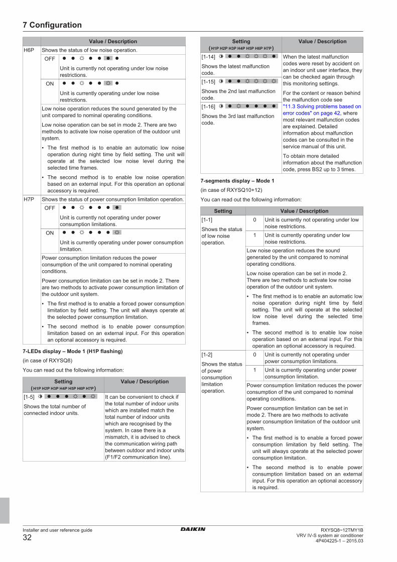
7 Configuration
Installer and user reference guide
32RXYSQ8~12TMY1B
VRV IV-S system air conditioner4P404225-1 – 2015.03
Value / DescriptionH6P Shows the status of low noise operation.
OFF
Unit is currently not operating under low noiserestrictions.
ON
Unit is currently operating under low noiserestrictions.
Low noise operation reduces the sound generated by theunit compared to nominal operating conditions.
Low noise operation can be set in mode 2. There are twomethods to activate low noise operation of the outdoor unitsystem.
▪ The first method is to enable an automatic low noiseoperation during night time by field setting. The unit willoperate at the selected low noise level during theselected time frames.
▪ The second method is to enable low noise operationbased on an external input. For this operation an optionalaccessory is required.
H7P Shows the status of power consumption limitation operation.OFF
Unit is currently not operating under powerconsumption limitations.
ON
Unit is currently operating under power consumptionlimitation.
Power consumption limitation reduces the powerconsumption of the unit compared to nominal operatingconditions.
Power consumption limitation can be set in mode 2. Thereare two methods to activate power consumption limitation ofthe outdoor unit system.
▪ The first method is to enable a forced power consumptionlimitation by field setting. The unit will always operate atthe selected power consumption limitation.
▪ The second method is to enable power consumptionlimitation based on an external input. For this operationan optional accessory is required.
7‑LEDs display – Mode 1 (H1P flashing)(in case of RXYSQ8)
You can read out the following information:
Setting( )
Value / Description
[1‑5]
Shows the total number ofconnected indoor units.
It can be convenient to check ifthe total number of indoor unitswhich are installed match thetotal number of indoor unitswhich are recognised by thesystem. In case there is amismatch, it is advised to checkthe communication wiring pathbetween outdoor and indoor units(F1/F2 communication line).
Setting( )
Value / Description
[1‑14]
Shows the latest malfunctioncode.
When the latest malfunctioncodes were reset by accident onan indoor unit user interface, theycan be checked again throughthis monitoring settings.
For the content or reason behindthe malfunction code see"11.3 Solving problems based onerror codes" on page 42, wheremost relevant malfunction codesare explained. Detailedinformation about malfunctioncodes can be consulted in theservice manual of this unit.
To obtain more detailedinformation about the malfunctioncode, press BS2 up to 3 times.
[1‑15]
Shows the 2nd last malfunctioncode.[1‑16]
Shows the 3rd last malfunctioncode.
7‑segments display – Mode 1(in case of RXYSQ10+12)
You can read out the following information:
Setting Value / Description[1‑1]
Shows the statusof low noiseoperation.
0 Unit is currently not operating under lownoise restrictions.
1 Unit is currently operating under lownoise restrictions.
Low noise operation reduces the soundgenerated by the unit compared to nominaloperating conditions.
Low noise operation can be set in mode 2.There are two methods to activate low noiseoperation of the outdoor unit system.
▪ The first method is to enable an automatic lownoise operation during night time by fieldsetting. The unit will operate at the selectedlow noise level during the selected timeframes.
▪ The second method is to enable low noiseoperation based on an external input. For thisoperation an optional accessory is required.
[1‑2]
Shows the statusof powerconsumptionlimitationoperation.
0 Unit is currently not operating underpower consumption limitations.
1 Unit is currently operating under powerconsumption limitation.
Power consumption limitation reduces the powerconsumption of the unit compared to nominaloperating conditions.
Power consumption limitation can be set inmode 2. There are two methods to activatepower consumption limitation of the outdoor unitsystem.
▪ The first method is to enable a forced powerconsumption limitation by field setting. Theunit will always operate at the selected powerconsumption limitation.
▪ The second method is to enable powerconsumption limitation based on an externalinput. For this operation an optional accessoryis required.
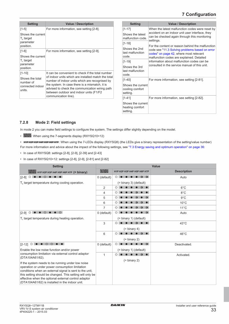
7 Configuration
Installer and user reference guide
33RXYSQ8~12TMY1BVRV IV-S system air conditioner4P404225-1 – 2015.03
Setting Value / Description[1‑5]
Shows the currentTe targetparameterposition.
For more information, see setting [2‑8].
[1‑6]
Shows the currentTc targetparameterposition.
For more information, see setting [2‑9].
[1‑10]
Shows the totalnumber ofconnected indoorunits.
It can be convenient to check if the total numberof indoor units which are installed match the totalnumber of indoor units which are recognised bythe system. In case there is a mismatch, it isadvised to check the communication wiring pathbetween outdoor and indoor units (F1/F2communication line).
Setting Value / Description[1‑17]
Shows the latestmalfunction code.
When the latest malfunction codes were reset byaccident on an indoor unit user interface, theycan be checked again through this monitoringsettings.
For the content or reason behind the malfunctioncode see "11.3 Solving problems based on errorcodes" on page 42, where most relevantmalfunction codes are explained. Detailedinformation about malfunction codes can beconsulted in the service manual of this unit.
[1‑18]
Shows the 2ndlast malfunctioncode.[1‑19]
Shows the 3rdlast malfunctioncode.[1‑40]
Shows the currentcooling comfortsetting.
For more information, see setting [2‑81].
[1‑41]
Shows the currentheating comfortsetting.
For more information, see setting [2‑82].
7.2.8 Mode 2: Field settings
In mode 2 you can make field settings to configure the system. The settings differ slightly depending on the model.
• : When using the 7‑segments display (RXYSQ10+12)
• : When using the 7‑LEDs display (RXYSQ8) (the LEDs give a binary representation of the setting/value number)For more information and advice about the impact of the following settings, see "7.3 Energy saving and optimum operation" on page 36:
• In case of RXYSQ8: settings [2‑8], [2‑9], [2‑39] and [2‑43]
• In case of RXYSQ10+12: settings [2‑8], [2‑9], [2‑81] and [2‑82]
Setting
(= binary)
ValueDescription
[2‑8]
Te target temperature during cooling operation.
0 (default)
(= binary 3) (default)
Auto
2 6°C4 8°C5 9°C6 10°C7 11°C
[2‑9]
Tc target temperature during heating operation.
0 (default)
(= binary 1) (default)
Auto
3
(= binary 4)
43°C
6
(= binary 2)
46°C
[2‑12]
Enable the low noise function and/or powerconsumption limitation via external control adaptor(DTA104A61/62).
If the system needs to be running under low noiseoperation or under power consumption limitationconditions when an external signal is sent to the unit,this setting should be changed. This setting will only beeffective when the optional external control adaptor(DTA104A61/62) is installed in the indoor unit.
0 (default)
(= binary 1) (default)
Deactivated.
1
(= binary 2)
Activated.
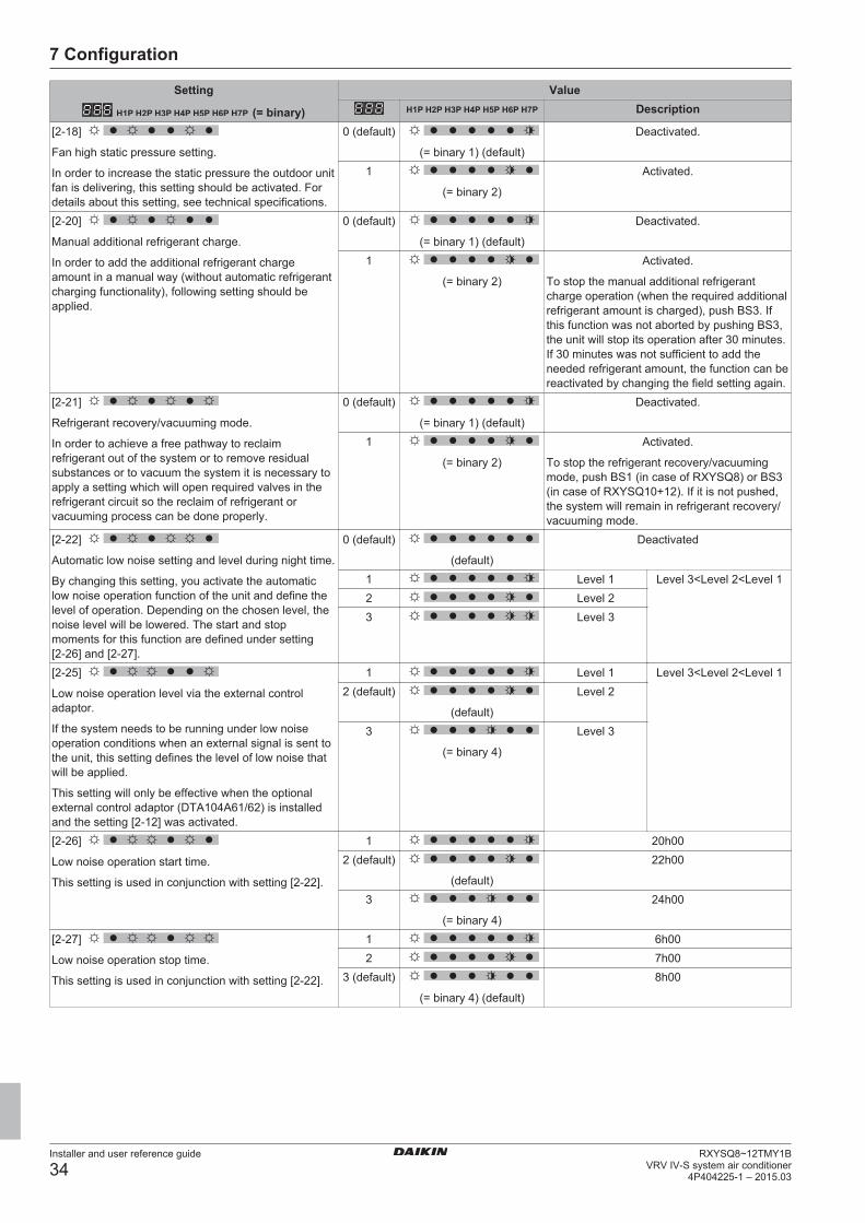
7 Configuration
Installer and user reference guide
34RXYSQ8~12TMY1B
VRV IV-S system air conditioner4P404225-1 – 2015.03
Setting
(= binary)
ValueDescription
[2‑18]
Fan high static pressure setting.
In order to increase the static pressure the outdoor unitfan is delivering, this setting should be activated. Fordetails about this setting, see technical specifications.
0 (default)
(= binary 1) (default)
Deactivated.
1
(= binary 2)
Activated.
[2‑20]
Manual additional refrigerant charge.
In order to add the additional refrigerant chargeamount in a manual way (without automatic refrigerantcharging functionality), following setting should beapplied.
0 (default)
(= binary 1) (default)
Deactivated.
1
(= binary 2)
Activated.
To stop the manual additional refrigerantcharge operation (when the required additionalrefrigerant amount is charged), push BS3. Ifthis function was not aborted by pushing BS3,the unit will stop its operation after 30 minutes.If 30 minutes was not sufficient to add theneeded refrigerant amount, the function can bereactivated by changing the field setting again.
[2‑21]
Refrigerant recovery/vacuuming mode.
In order to achieve a free pathway to reclaimrefrigerant out of the system or to remove residualsubstances or to vacuum the system it is necessary toapply a setting which will open required valves in therefrigerant circuit so the reclaim of refrigerant orvacuuming process can be done properly.
0 (default)
(= binary 1) (default)
Deactivated.
1
(= binary 2)
Activated.
To stop the refrigerant recovery/vacuumingmode, push BS1 (in case of RXYSQ8) or BS3(in case of RXYSQ10+12). If it is not pushed,the system will remain in refrigerant recovery/vacuuming mode.
[2‑22]
Automatic low noise setting and level during night time.
By changing this setting, you activate the automaticlow noise operation function of the unit and define thelevel of operation. Depending on the chosen level, thenoise level will be lowered. The start and stopmoments for this function are defined under setting[2‑26] and [2‑27].
0 (default)
(default)
Deactivated
1 Level 1 Level 3<Level 2<Level 12 Level 23 Level 3
[2‑25]
Low noise operation level via the external controladaptor.
If the system needs to be running under low noiseoperation conditions when an external signal is sent tothe unit, this setting defines the level of low noise thatwill be applied.
This setting will only be effective when the optionalexternal control adaptor (DTA104A61/62) is installedand the setting [2‑12] was activated.
1 Level 1 Level 3<Level 2<Level 12 (default)
(default)
Level 2
3
(= binary 4)
Level 3
[2‑26]
Low noise operation start time.
This setting is used in conjunction with setting [2‑22].
1 20h002 (default)
(default)
22h00
3
(= binary 4)
24h00
[2‑27]
Low noise operation stop time.
This setting is used in conjunction with setting [2‑22].
1 6h002 7h00
3 (default)
(= binary 4) (default)
8h00
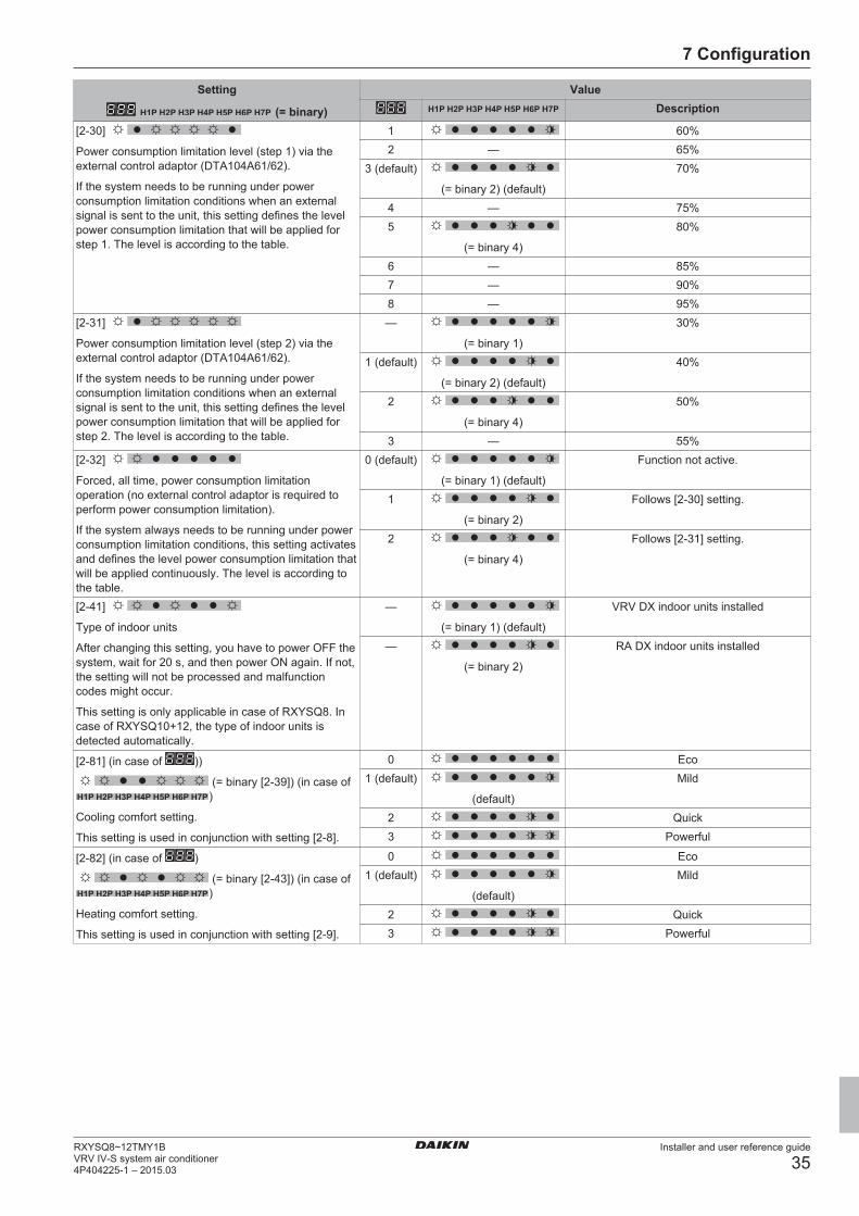
7 Configuration
Installer and user reference guide
35RXYSQ8~12TMY1BVRV IV-S system air conditioner4P404225-1 – 2015.03
Setting
(= binary)
ValueDescription
[2‑30]
Power consumption limitation level (step 1) via theexternal control adaptor (DTA104A61/62).
If the system needs to be running under powerconsumption limitation conditions when an externalsignal is sent to the unit, this setting defines the levelpower consumption limitation that will be applied forstep 1. The level is according to the table.
1 60%2 — 65%
3 (default)
(= binary 2) (default)
70%
4 — 75%5
(= binary 4)
80%
6 — 85%7 — 90%8 — 95%
[2‑31]
Power consumption limitation level (step 2) via theexternal control adaptor (DTA104A61/62).
If the system needs to be running under powerconsumption limitation conditions when an externalsignal is sent to the unit, this setting defines the levelpower consumption limitation that will be applied forstep 2. The level is according to the table.
—
(= binary 1)
30%
1 (default)
(= binary 2) (default)
40%
2
(= binary 4)
50%
3 — 55%[2‑32]
Forced, all time, power consumption limitationoperation (no external control adaptor is required toperform power consumption limitation).
If the system always needs to be running under powerconsumption limitation conditions, this setting activatesand defines the level power consumption limitation thatwill be applied continuously. The level is according tothe table.
0 (default)
(= binary 1) (default)
Function not active.
1
(= binary 2)
Follows [2‑30] setting.
2
(= binary 4)
Follows [2‑31] setting.
[2‑41]
Type of indoor units
After changing this setting, you have to power OFF thesystem, wait for 20 s, and then power ON again. If not,the setting will not be processed and malfunctioncodes might occur.
This setting is only applicable in case of RXYSQ8. Incase of RXYSQ10+12, the type of indoor units isdetected automatically.
—
(= binary 1) (default)
VRV DX indoor units installed
—
(= binary 2)
RA DX indoor units installed
[2‑81] (in case of ))
(= binary [2‑39]) (in case of)
Cooling comfort setting.
This setting is used in conjunction with setting [2‑8].
0 Eco1 (default)
(default)
Mild
2 Quick3 Powerful
[2‑82] (in case of )
(= binary [2‑43]) (in case of)
Heating comfort setting.
This setting is used in conjunction with setting [2‑9].
0 Eco1 (default)
(default)
Mild
2 Quick3 Powerful
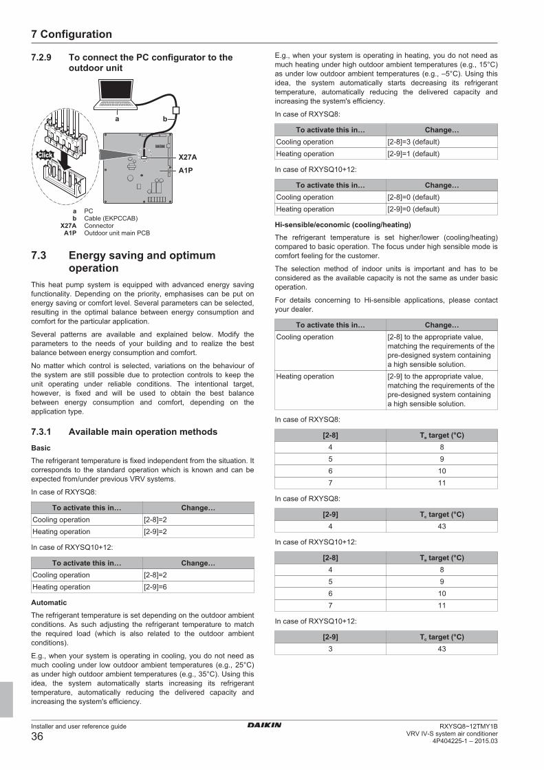
7 Configuration
Installer and user reference guide
36RXYSQ8~12TMY1B
VRV IV-S system air conditioner4P404225-1 – 2015.03
7.2.9 To connect the PC configurator to theoutdoor unit
23
45
H JS
T
a b
X27A
A1P
a PCb Cable (EKPCCAB)
X27A ConnectorA1P Outdoor unit main PCB
7.3 Energy saving and optimumoperation
This heat pump system is equipped with advanced energy savingfunctionality. Depending on the priority, emphasises can be put onenergy saving or comfort level. Several parameters can be selected,resulting in the optimal balance between energy consumption andcomfort for the particular application.
Several patterns are available and explained below. Modify theparameters to the needs of your building and to realize the bestbalance between energy consumption and comfort.
No matter which control is selected, variations on the behaviour ofthe system are still possible due to protection controls to keep theunit operating under reliable conditions. The intentional target,however, is fixed and will be used to obtain the best balancebetween energy consumption and comfort, depending on theapplication type.
7.3.1 Available main operation methodsBasicThe refrigerant temperature is fixed independent from the situation. Itcorresponds to the standard operation which is known and can beexpected from/under previous VRV systems.
In case of RXYSQ8:
To activate this in… Change…Cooling operation [2‑8]=2Heating operation [2‑9]=2
In case of RXYSQ10+12:
To activate this in… Change…Cooling operation [2‑8]=2Heating operation [2‑9]=6
AutomaticThe refrigerant temperature is set depending on the outdoor ambientconditions. As such adjusting the refrigerant temperature to matchthe required load (which is also related to the outdoor ambientconditions).
E.g., when your system is operating in cooling, you do not need asmuch cooling under low outdoor ambient temperatures (e.g., 25°C)as under high outdoor ambient temperatures (e.g., 35°C). Using thisidea, the system automatically starts increasing its refrigeranttemperature, automatically reducing the delivered capacity andincreasing the system's efficiency.
E.g., when your system is operating in heating, you do not need asmuch heating under high outdoor ambient temperatures (e.g., 15°C)as under low outdoor ambient temperatures (e.g., –5°C). Using thisidea, the system automatically starts decreasing its refrigeranttemperature, automatically reducing the delivered capacity andincreasing the system's efficiency.
In case of RXYSQ8:
To activate this in… Change…Cooling operation [2‑8]=3 (default)Heating operation [2‑9]=1 (default)
In case of RXYSQ10+12:
To activate this in… Change…Cooling operation [2‑8]=0 (default)Heating operation [2‑9]=0 (default)
Hi-sensible/economic (cooling/heating)The refrigerant temperature is set higher/lower (cooling/heating)compared to basic operation. The focus under high sensible mode iscomfort feeling for the customer.
The selection method of indoor units is important and has to beconsidered as the available capacity is not the same as under basicoperation.
For details concerning to Hi-sensible applications, please contactyour dealer.
To activate this in… Change…Cooling operation [2‑8] to the appropriate value,
matching the requirements of thepre-designed system containinga high sensible solution.
Heating operation [2‑9] to the appropriate value,matching the requirements of thepre-designed system containinga high sensible solution.
In case of RXYSQ8:
[2‑8] Te target (°C)4 85 96 107 11
In case of RXYSQ8:
[2‑9] Tc target (°C)4 43
In case of RXYSQ10+12:
[2‑8] Te target (°C)4 85 96 107 11
In case of RXYSQ10+12:
[2‑9] Tc target (°C)3 43
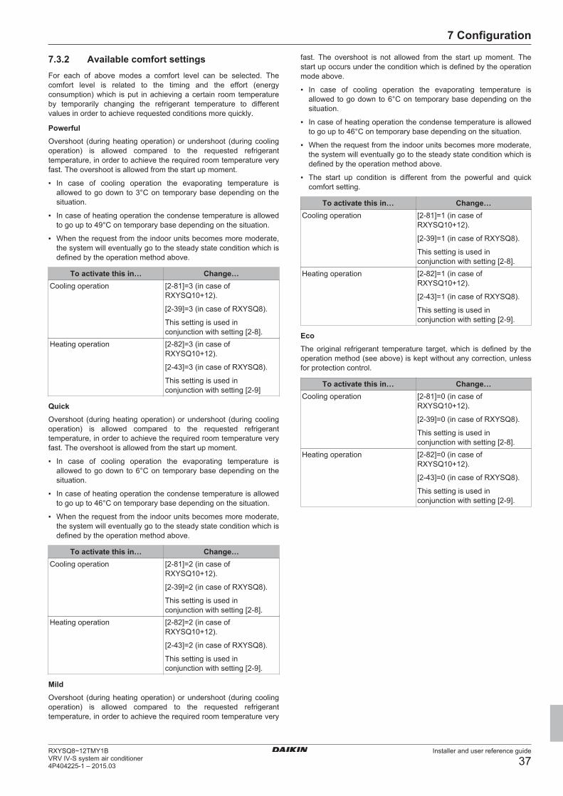
7 Configuration
Installer and user reference guide
37RXYSQ8~12TMY1BVRV IV-S system air conditioner4P404225-1 – 2015.03
7.3.2 Available comfort settingsFor each of above modes a comfort level can be selected. Thecomfort level is related to the timing and the effort (energyconsumption) which is put in achieving a certain room temperatureby temporarily changing the refrigerant temperature to differentvalues in order to achieve requested conditions more quickly.
PowerfulOvershoot (during heating operation) or undershoot (during coolingoperation) is allowed compared to the requested refrigeranttemperature, in order to achieve the required room temperature veryfast. The overshoot is allowed from the start up moment.
▪ In case of cooling operation the evaporating temperature isallowed to go down to 3°C on temporary base depending on thesituation.
▪ In case of heating operation the condense temperature is allowedto go up to 49°C on temporary base depending on the situation.
▪ When the request from the indoor units becomes more moderate,the system will eventually go to the steady state condition which isdefined by the operation method above.
To activate this in… Change…Cooling operation [2‑81]=3 (in case of
RXYSQ10+12).
[2‑39]=3 (in case of RXYSQ8).
This setting is used inconjunction with setting [2‑8].
Heating operation [2‑82]=3 (in case ofRXYSQ10+12).
[2‑43]=3 (in case of RXYSQ8).
This setting is used inconjunction with setting [2‑9]
QuickOvershoot (during heating operation) or undershoot (during coolingoperation) is allowed compared to the requested refrigeranttemperature, in order to achieve the required room temperature veryfast. The overshoot is allowed from the start up moment.
▪ In case of cooling operation the evaporating temperature isallowed to go down to 6°C on temporary base depending on thesituation.
▪ In case of heating operation the condense temperature is allowedto go up to 46°C on temporary base depending on the situation.
▪ When the request from the indoor units becomes more moderate,the system will eventually go to the steady state condition which isdefined by the operation method above.
To activate this in… Change…Cooling operation [2‑81]=2 (in case of
RXYSQ10+12).
[2‑39]=2 (in case of RXYSQ8).
This setting is used inconjunction with setting [2‑8].
Heating operation [2‑82]=2 (in case ofRXYSQ10+12).
[2‑43]=2 (in case of RXYSQ8).
This setting is used inconjunction with setting [2‑9].
MildOvershoot (during heating operation) or undershoot (during coolingoperation) is allowed compared to the requested refrigeranttemperature, in order to achieve the required room temperature very
fast. The overshoot is not allowed from the start up moment. Thestart up occurs under the condition which is defined by the operationmode above.
▪ In case of cooling operation the evaporating temperature isallowed to go down to 6°C on temporary base depending on thesituation.
▪ In case of heating operation the condense temperature is allowedto go up to 46°C on temporary base depending on the situation.
▪ When the request from the indoor units becomes more moderate,the system will eventually go to the steady state condition which isdefined by the operation method above.
▪ The start up condition is different from the powerful and quickcomfort setting.
To activate this in… Change…Cooling operation [2‑81]=1 (in case of
RXYSQ10+12).
[2‑39]=1 (in case of RXYSQ8).
This setting is used inconjunction with setting [2‑8].
Heating operation [2‑82]=1 (in case ofRXYSQ10+12).
[2‑43]=1 (in case of RXYSQ8).
This setting is used inconjunction with setting [2‑9].
EcoThe original refrigerant temperature target, which is defined by theoperation method (see above) is kept without any correction, unlessfor protection control.
To activate this in… Change…Cooling operation [2‑81]=0 (in case of
RXYSQ10+12).
[2‑39]=0 (in case of RXYSQ8).
This setting is used inconjunction with setting [2‑8].
Heating operation [2‑82]=0 (in case ofRXYSQ10+12).
[2‑43]=0 (in case of RXYSQ8).
This setting is used inconjunction with setting [2‑9].
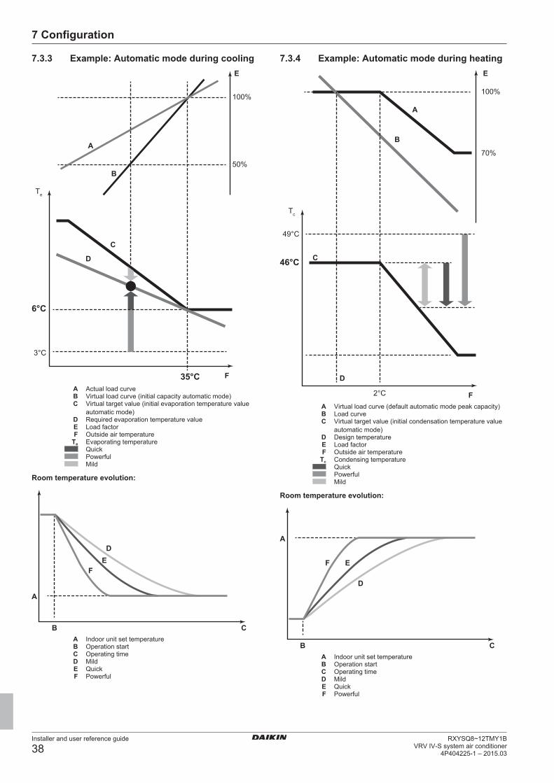
7 Configuration
Installer and user reference guide
38RXYSQ8~12TMY1B
VRV IV-S system air conditioner4P404225-1 – 2015.03
7.3.3 Example: Automatic mode during cooling
A
B
E
100%
50%
Te
C
D
3°C
6°C
35°C FA Actual load curveB Virtual load curve (initial capacity automatic mode)C Virtual target value (initial evaporation temperature value
automatic mode)D Required evaporation temperature valueE Load factorF Outside air temperature
Te Evaporating temperatureQuickPowerfulMild
Room temperature evolution:
A
B C
DE
F
A Indoor unit set temperatureB Operation startC Operating timeD MildE QuickF Powerful
7.3.4 Example: Automatic mode during heating
A
B
100%
70%
E
Tc
C
D
49°C
46°C
F2°C
A Virtual load curve (default automatic mode peak capacity)B Load curveC Virtual target value (initial condensation temperature value
automatic mode)D Design temperatureE Load factorF Outside air temperature
Tc Condensing temperatureQuickPowerfulMild
Room temperature evolution:
A
B C
D
EF
A Indoor unit set temperatureB Operation startC Operating timeD MildE QuickF Powerful
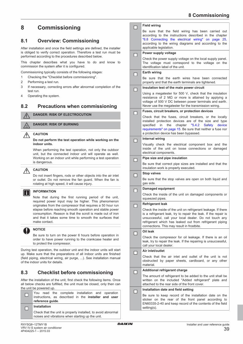
8 Commissioning
Installer and user reference guide
39RXYSQ8~12TMY1BVRV IV-S system air conditioner4P404225-1 – 2015.03
8 Commissioning
8.1 Overview: CommissioningAfter installation and once the field settings are defined, the installeris obliged to verify correct operation. Therefore a test run must beperformed according to the procedures described below.
This chapter describes what you have to do and know tocommission the system after it is configured.
Commissioning typically consists of the following stages:1 Checking the "Checklist before commissioning".2 Performing a test run.3 If necessary, correcting errors after abnormal completion of the
test run.4 Operating the system.
8.2 Precautions when commissioningDANGER: RISK OF ELECTROCUTION
DANGER: RISK OF BURNING
CAUTION
Do not perform the test operation while working on theindoor units.
When performing the test operation, not only the outdoorunit, but the connected indoor unit will operate as well.Working on an indoor unit while performing a test operationis dangerous.
CAUTION
Do not insert fingers, rods or other objects into the air inletor outlet. Do not remove the fan guard. When the fan isrotating at high speed, it will cause injury.
INFORMATION
Note that during the first running period of the unit,required power input may be higher. This phenomenonoriginates from the compressor that requires a 50 hour runelapse before reaching smooth operation and stable powerconsumption. Reason is that the scroll is made out of ironand that it takes some time to smooth the surfaces thatmake contact.
NOTICE
Be sure to turn on the power 6 hours before operation inorder to have power running to the crankcase heater andto protect the compressor.
During test operation, the outdoor unit and the indoor units will startup. Make sure that the preparations of all indoor units are finished(field piping, electrical wiring, air purge, ...). See installation manualof the indoor units for details.
8.3 Checklist before commissioningAfter the installation of the unit, first check the following items. Onceall below checks are fulfilled, the unit must be closed, only then canthe unit be powered up.
You read the complete installation and operationinstructions, as described in the installer and userreference guide.Installation
Check that the unit is properly installed, to avoid abnormalnoises and vibrations when starting up the unit.
Field wiring
Be sure that the field wiring has been carried outaccording to the instructions described in the chapter"6.8 Connecting the electrical wiring" on page 25,according to the wiring diagrams and according to theapplicable legislation.Power supply voltage
Check the power supply voltage on the local supply panel.The voltage must correspond to the voltage on theidentification label of the unit.Earth wiring
Be sure that the earth wires have been connectedproperly and that the earth terminals are tightened.Insulation test of the main power circuit
Using a megatester for 500 V, check that the insulationresistance of 2 MΩ or more is attained by applying avoltage of 500 V DC between power terminals and earth.Never use the megatester for the transmission wiring.Fuses, circuit breakers, or protection devices
Check that the fuses, circuit breakers, or the locallyinstalled protection devices are of the size and typespecified in the chapter "5.4.2 Safety devicerequirements" on page 15. Be sure that neither a fuse nora protection device has been bypassed.Internal wiring
Visually check the electrical component box and theinside of the unit on loose connections or damagedelectrical components.Pipe size and pipe insulation
Be sure that correct pipe sizes are installed and that theinsulation work is properly executed.Stop valves
Be sure that the stop valves are open on both liquid andgas side.Damaged equipment
Check the inside of the unit on damaged components orsqueezed pipes.Refrigerant leak
Check the inside of the unit on refrigerant leakage. If thereis a refrigerant leak, try to repair the leak. If the repair isunsuccessful, call your local dealer. Do not touch anyrefrigerant which has leaked out from refrigerant pipingconnections. This may result in frostbite.Oil leak
Check the compressor for oil leakage. If there is an oilleak, try to repair the leak. If the repairing is unsuccessful,call your local dealer.Air inlet/outlet
Check that the air inlet and outlet of the unit is notobstructed by paper sheets, cardboard, or any othermaterial.Additional refrigerant charge
The amount of refrigerant to be added to the unit shall bewritten on the included "Added refrigerant" plate andattached to the rear side of the front cover.Installation date and field setting
Be sure to keep record of the installation date on thesticker on the rear of the front panel according toEN60335‑2‑40 and keep record of the contents of the fieldsetting(s).
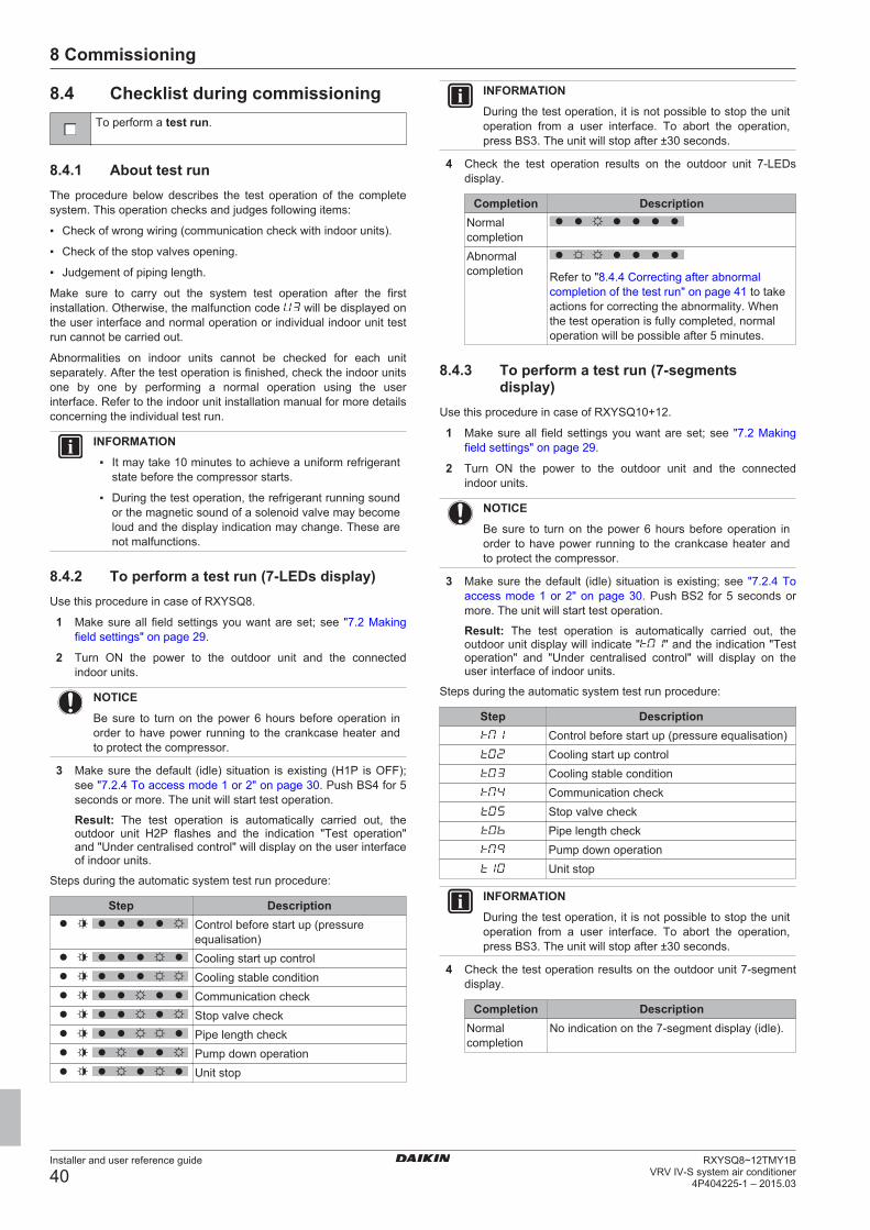
8 Commissioning
Installer and user reference guide
40RXYSQ8~12TMY1B
VRV IV-S system air conditioner4P404225-1 – 2015.03
8.4 Checklist during commissioningTo perform a test run.
8.4.1 About test runThe procedure below describes the test operation of the completesystem. This operation checks and judges following items:
▪ Check of wrong wiring (communication check with indoor units).
▪ Check of the stop valves opening.
▪ Judgement of piping length.
Make sure to carry out the system test operation after the firstinstallation. Otherwise, the malfunction code will be displayed onthe user interface and normal operation or individual indoor unit testrun cannot be carried out.
Abnormalities on indoor units cannot be checked for each unitseparately. After the test operation is finished, check the indoor unitsone by one by performing a normal operation using the userinterface. Refer to the indoor unit installation manual for more detailsconcerning the individual test run.
INFORMATION
▪ It may take 10 minutes to achieve a uniform refrigerantstate before the compressor starts.
▪ During the test operation, the refrigerant running soundor the magnetic sound of a solenoid valve may becomeloud and the display indication may change. These arenot malfunctions.
8.4.2 To perform a test run (7-LEDs display)Use this procedure in case of RXYSQ8.
1 Make sure all field settings you want are set; see "7.2 Makingfield settings" on page 29.
2 Turn ON the power to the outdoor unit and the connectedindoor units.
NOTICE
Be sure to turn on the power 6 hours before operation inorder to have power running to the crankcase heater andto protect the compressor.
3 Make sure the default (idle) situation is existing (H1P is OFF);see "7.2.4 To access mode 1 or 2" on page 30. Push BS4 for 5seconds or more. The unit will start test operation.
Result: The test operation is automatically carried out, theoutdoor unit H2P flashes and the indication "Test operation"and "Under centralised control" will display on the user interfaceof indoor units.
Steps during the automatic system test run procedure:
Step DescriptionControl before start up (pressureequalisation)Cooling start up controlCooling stable conditionCommunication checkStop valve checkPipe length checkPump down operationUnit stop
INFORMATION
During the test operation, it is not possible to stop the unitoperation from a user interface. To abort the operation,press BS3. The unit will stop after ±30 seconds.
4 Check the test operation results on the outdoor unit 7‑LEDsdisplay.
Completion DescriptionNormalcompletionAbnormalcompletion Refer to "8.4.4 Correcting after abnormal
completion of the test run" on page 41 to takeactions for correcting the abnormality. Whenthe test operation is fully completed, normaloperation will be possible after 5 minutes.
8.4.3 To perform a test run (7-segmentsdisplay)
Use this procedure in case of RXYSQ10+12.
1 Make sure all field settings you want are set; see "7.2 Makingfield settings" on page 29.
2 Turn ON the power to the outdoor unit and the connectedindoor units.
NOTICE
Be sure to turn on the power 6 hours before operation inorder to have power running to the crankcase heater andto protect the compressor.
3 Make sure the default (idle) situation is existing; see "7.2.4 Toaccess mode 1 or 2" on page 30. Push BS2 for 5 seconds ormore. The unit will start test operation.
Result: The test operation is automatically carried out, theoutdoor unit display will indicate " " and the indication "Testoperation" and "Under centralised control" will display on theuser interface of indoor units.
Steps during the automatic system test run procedure:
Step DescriptionControl before start up (pressure equalisation)Cooling start up controlCooling stable conditionCommunication checkStop valve checkPipe length checkPump down operationUnit stop
INFORMATION
During the test operation, it is not possible to stop the unitoperation from a user interface. To abort the operation,press BS3. The unit will stop after ±30 seconds.
4 Check the test operation results on the outdoor unit 7‑segmentdisplay.
Completion DescriptionNormalcompletion
No indication on the 7‑segment display (idle).
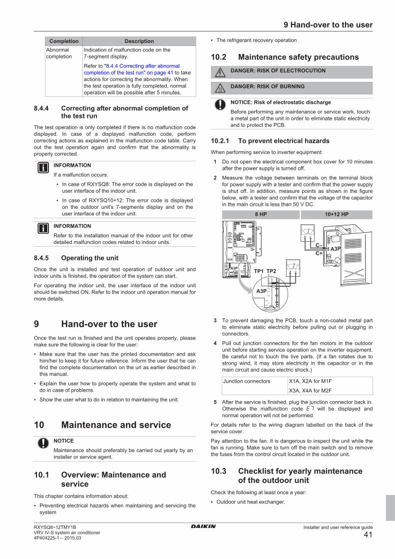
9 Hand-over to the user
Installer and user reference guide
41RXYSQ8~12TMY1BVRV IV-S system air conditioner4P404225-1 – 2015.03
Completion DescriptionAbnormalcompletion
Indication of malfunction code on the7‑segment display.
Refer to "8.4.4 Correcting after abnormalcompletion of the test run" on page 41 to takeactions for correcting the abnormality. Whenthe test operation is fully completed, normaloperation will be possible after 5 minutes.
8.4.4 Correcting after abnormal completion ofthe test run
The test operation is only completed if there is no malfunction codedisplayed. In case of a displayed malfunction code, performcorrecting actions as explained in the malfunction code table. Carryout the test operation again and confirm that the abnormality isproperly corrected.
INFORMATION
If a malfunction occurs:
▪ In case of RXYSQ8: The error code is displayed on theuser interface of the indoor unit.
▪ In case of RXYSQ10+12: The error code is displayedon the outdoor unit's 7‑segments display and on theuser interface of the indoor unit.
INFORMATION
Refer to the installation manual of the indoor unit for otherdetailed malfunction codes related to indoor units.
8.4.5 Operating the unitOnce the unit is installed and test operation of outdoor unit andindoor units is finished, the operation of the system can start.
For operating the indoor unit, the user interface of the indoor unitshould be switched ON. Refer to the indoor unit operation manual formore details.
9 Hand-over to the userOnce the test run is finished and the unit operates properly, pleasemake sure the following is clear for the user:
▪ Make sure that the user has the printed documentation and askhim/her to keep it for future reference. Inform the user that he canfind the complete documentation on the url as earlier described inthis manual.
▪ Explain the user how to properly operate the system and what todo in case of problems.
▪ Show the user what to do in relation to maintaining the unit.
10 Maintenance and serviceNOTICE
Maintenance should preferably be carried out yearly by aninstaller or service agent.
10.1 Overview: Maintenance andservice
This chapter contains information about:
▪ Preventing electrical hazards when maintaining and servicing thesystem
▪ The refrigerant recovery operation
10.2 Maintenance safety precautionsDANGER: RISK OF ELECTROCUTION
DANGER: RISK OF BURNING
NOTICE: Risk of electrostatic discharge
Before performing any maintenance or service work, toucha metal part of the unit in order to eliminate static electricityand to protect the PCB.
10.2.1 To prevent electrical hazardsWhen performing service to inverter equipment:
1 Do not open the electrical component box cover for 10 minutesafter the power supply is turned off.
2 Measure the voltage between terminals on the terminal blockfor power supply with a tester and confirm that the power supplyis shut off. In addition, measure points as shown in the figurebelow, with a tester and confirm that the voltage of the capacitorin the main circuit is less than 50 V DC.
10+12 HP
A3P
A3P
TP2TP1
8 HP
A3PC–C+
3 To prevent damaging the PCB, touch a non-coated metal partto eliminate static electricity before pulling out or plugging inconnectors.
4 Pull out junction connectors for the fan motors in the outdoorunit before starting service operation on the inverter equipment.Be careful not to touch the live parts. (If a fan rotates due tostrong wind, it may store electricity in the capacitor or in themain circuit and cause electric shock.)
Junction connectors X1A, X2A for M1F
X3A, X4A for M2F
5 After the service is finished, plug the junction connector back in.Otherwise the malfunction code will be displayed andnormal operation will not be performed.
For details refer to the wiring diagram labelled on the back of theservice cover.
Pay attention to the fan. It is dangerous to inspect the unit while thefan is running. Make sure to turn off the main switch and to removethe fuses from the control circuit located in the outdoor unit.
10.3 Checklist for yearly maintenanceof the outdoor unit
Check the following at least once a year:
▪ Outdoor unit heat exchanger.
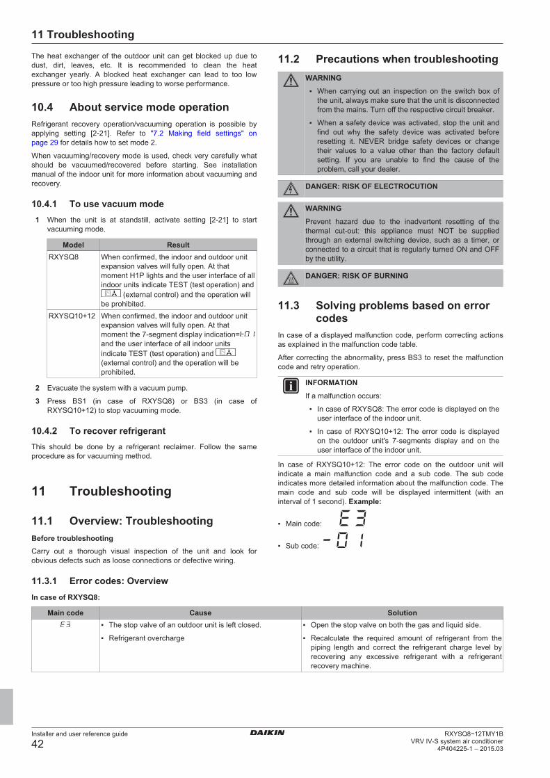
11 Troubleshooting
Installer and user reference guide
42RXYSQ8~12TMY1B
VRV IV-S system air conditioner4P404225-1 – 2015.03
The heat exchanger of the outdoor unit can get blocked up due todust, dirt, leaves, etc. It is recommended to clean the heatexchanger yearly. A blocked heat exchanger can lead to too lowpressure or too high pressure leading to worse performance.
10.4 About service mode operationRefrigerant recovery operation/vacuuming operation is possible byapplying setting [2‑21]. Refer to "7.2 Making field settings" onpage 29 for details how to set mode 2.
When vacuuming/recovery mode is used, check very carefully whatshould be vacuumed/recovered before starting. See installationmanual of the indoor unit for more information about vacuuming andrecovery.
10.4.1 To use vacuum mode1 When the unit is at standstill, activate setting [2‑21] to start
vacuuming mode.
Model ResultRXYSQ8 When confirmed, the indoor and outdoor unit
expansion valves will fully open. At thatmoment H1P lights and the user interface of allindoor units indicate TEST (test operation) and
(external control) and the operation willbe prohibited.
RXYSQ10+12 When confirmed, the indoor and outdoor unitexpansion valves will fully open. At thatmoment the 7‑segment display indication=and the user interface of all indoor unitsindicate TEST (test operation) and (external control) and the operation will beprohibited.
2 Evacuate the system with a vacuum pump.
3 Press BS1 (in case of RXYSQ8) or BS3 (in case ofRXYSQ10+12) to stop vacuuming mode.
10.4.2 To recover refrigerantThis should be done by a refrigerant reclaimer. Follow the sameprocedure as for vacuuming method.
11 Troubleshooting
11.1 Overview: TroubleshootingBefore troubleshootingCarry out a thorough visual inspection of the unit and look forobvious defects such as loose connections or defective wiring.
11.2 Precautions when troubleshootingWARNING
▪ When carrying out an inspection on the switch box ofthe unit, always make sure that the unit is disconnectedfrom the mains. Turn off the respective circuit breaker.
▪ When a safety device was activated, stop the unit andfind out why the safety device was activated beforeresetting it. NEVER bridge safety devices or changetheir values to a value other than the factory defaultsetting. If you are unable to find the cause of theproblem, call your dealer.
DANGER: RISK OF ELECTROCUTION
WARNING
Prevent hazard due to the inadvertent resetting of thethermal cut-out: this appliance must NOT be suppliedthrough an external switching device, such as a timer, orconnected to a circuit that is regularly turned ON and OFFby the utility.
DANGER: RISK OF BURNING
11.3 Solving problems based on errorcodes
In case of a displayed malfunction code, perform correcting actionsas explained in the malfunction code table.
After correcting the abnormality, press BS3 to reset the malfunctioncode and retry operation.
INFORMATION
If a malfunction occurs:
▪ In case of RXYSQ8: The error code is displayed on theuser interface of the indoor unit.
▪ In case of RXYSQ10+12: The error code is displayedon the outdoor unit's 7‑segments display and on theuser interface of the indoor unit.
In case of RXYSQ10+12: The error code on the outdoor unit willindicate a main malfunction code and a sub code. The sub codeindicates more detailed information about the malfunction code. Themain code and sub code will be displayed intermittent (with aninterval of 1 second). Example:
▪ Main code:
▪ Sub code:
11.3.1 Error codes: OverviewIn case of RXYSQ8:
Main code Cause Solution▪ The stop valve of an outdoor unit is left closed.
▪ Refrigerant overcharge
▪ Open the stop valve on both the gas and liquid side.
▪ Recalculate the required amount of refrigerant from thepiping length and correct the refrigerant charge level byrecovering any excessive refrigerant with a refrigerantrecovery machine.
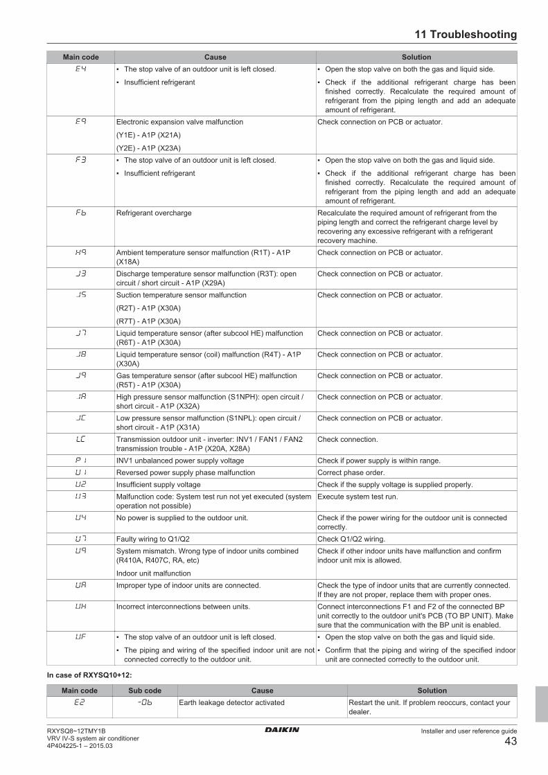
11 Troubleshooting
Installer and user reference guide
43RXYSQ8~12TMY1BVRV IV-S system air conditioner4P404225-1 – 2015.03
Main code Cause Solution▪ The stop valve of an outdoor unit is left closed.
▪ Insufficient refrigerant
▪ Open the stop valve on both the gas and liquid side.
▪ Check if the additional refrigerant charge has beenfinished correctly. Recalculate the required amount ofrefrigerant from the piping length and add an adequateamount of refrigerant.
Electronic expansion valve malfunction
(Y1E) - A1P (X21A)
(Y2E) - A1P (X23A)
Check connection on PCB or actuator.
▪ The stop valve of an outdoor unit is left closed.
▪ Insufficient refrigerant
▪ Open the stop valve on both the gas and liquid side.
▪ Check if the additional refrigerant charge has beenfinished correctly. Recalculate the required amount ofrefrigerant from the piping length and add an adequateamount of refrigerant.
Refrigerant overcharge Recalculate the required amount of refrigerant from thepiping length and correct the refrigerant charge level byrecovering any excessive refrigerant with a refrigerantrecovery machine.
Ambient temperature sensor malfunction (R1T) - A1P(X18A)
Check connection on PCB or actuator.
Discharge temperature sensor malfunction (R3T): opencircuit / short circuit - A1P (X29A)
Check connection on PCB or actuator.
Suction temperature sensor malfunction
(R2T) - A1P (X30A)
(R7T) - A1P (X30A)
Check connection on PCB or actuator.
Liquid temperature sensor (after subcool HE) malfunction(R6T) - A1P (X30A)
Check connection on PCB or actuator.
Liquid temperature sensor (coil) malfunction (R4T) - A1P(X30A)
Check connection on PCB or actuator.
Gas temperature sensor (after subcool HE) malfunction(R5T) - A1P (X30A)
Check connection on PCB or actuator.
High pressure sensor malfunction (S1NPH): open circuit /short circuit - A1P (X32A)
Check connection on PCB or actuator.
Low pressure sensor malfunction (S1NPL): open circuit /short circuit - A1P (X31A)
Check connection on PCB or actuator.
Transmission outdoor unit - inverter: INV1 / FAN1 / FAN2transmission trouble - A1P (X20A, X28A)
Check connection.
INV1 unbalanced power supply voltage Check if power supply is within range.Reversed power supply phase malfunction Correct phase order.Insufficient supply voltage Check if the supply voltage is supplied properly.Malfunction code: System test run not yet executed (systemoperation not possible)
Execute system test run.
No power is supplied to the outdoor unit. Check if the power wiring for the outdoor unit is connectedcorrectly.
Faulty wiring to Q1/Q2 Check Q1/Q2 wiring.System mismatch. Wrong type of indoor units combined(R410A, R407C, RA, etc)
Indoor unit malfunction
Check if other indoor units have malfunction and confirmindoor unit mix is allowed.
Improper type of indoor units are connected. Check the type of indoor units that are currently connected.If they are not proper, replace them with proper ones.
Incorrect interconnections between units. Connect interconnections F1 and F2 of the connected BPunit correctly to the outdoor unit's PCB (TO BP UNIT). Makesure that the communication with the BP unit is enabled.
▪ The stop valve of an outdoor unit is left closed.
▪ The piping and wiring of the specified indoor unit are notconnected correctly to the outdoor unit.
▪ Open the stop valve on both the gas and liquid side.
▪ Confirm that the piping and wiring of the specified indoorunit are connected correctly to the outdoor unit.
In case of RXYSQ10+12:
Main code Sub code Cause SolutionEarth leakage detector activated Restart the unit. If problem reoccurs, contact your
dealer.

11 Troubleshooting
Installer and user reference guide
44RXYSQ8~12TMY1B
VRV IV-S system air conditioner4P404225-1 – 2015.03
Main code Sub code Cause SolutionHigh pressure switch was activated (S1PH) - A1P(X4A)
Check stop valve situation or abnormalities in(field) piping or airflow over air cooled coil.
▪ Refrigerant overcharge
▪ Stop valve closed
▪ Check refrigerant amount+recharge unit.
▪ Open stop valvesStop valve closed (liquid) Open liquid stop valve.▪ Refrigerant overcharge
▪ Stop valve closed
▪ Check refrigerant amount+recharge unit.
▪ Open stop valves.Low pressure malfunction:
▪ Stop valve closed
▪ Refrigerant shortage
▪ Indoor unit malfunction
▪ Open stop valves.
▪ Check refrigerant amount+recharge unit.
▪ Check the user interface's display ortransmission wiring between the outdoor unitand the indoor unit.
Electronic expansion valve malfunction (subcool)(Y2E) - A1P (X21A)
Check connection on PCB or actuator.
Electronic expansion valve malfunction (main)(Y1E) - A1P (X23A)
Check connection on PCB or actuator.
Discharge temperature too high (R21T):
▪ Stop valve closed
▪ Refrigerant shortage
▪ Open stop valves.
▪ Check refrigerant amount+recharge unit.
Compressor casing temperature too high (R8T):
▪ Stop valve closed
▪ Refrigerant shortage
▪ Open stop valves.
▪ Check refrigerant amount+recharge unit.
▪ Refrigerant overcharge
▪ Stop valve closed
▪ Check refrigerant amount+recharge unit.
▪ Open stop valves.Ambient temperature sensor malfunction (R1T) -A1P (X18A)
Check connection on PCB or actuator.
Discharge temperature sensor malfunction (R21T):open circuit - A1P (X29A)
Check connection on PCB or actuator.
Discharge temperature sensor malfunction (R21T):short circuit - A1P (X29A)
Check connection on PCB or actuator.
Compressor casing temperature sensormalfunction (R8T): open circuit - A1P (X29A)
Check connection on PCB or actuator.
Compressor casing temperature sensormalfunction (R8T): short circuit - A1P (X29A)
Check connection on PCB or actuator.
Suction temperature sensor malfunction (R3T) -A1P (X30A)
Check connection on PCB or actuator.
De-icing temperature sensor malfunction (R7T) -A1P (X30A)
Check connection on PCB or actuator
Liquid temperature sensor (after subcool HE)malfunction (R5T) - A1P (X30A)
Check connection on PCB or actuator.
Liquid temperature sensor (coil) malfunction (R4T)- A1P (X30A)
Check connection on PCB or actuator.
Gas temperature sensor (after subcool HE)malfunction (R6T) - A1P (X30A)
Check connection on PCB or actuator.
High pressure sensor malfunction (S1NPH): opencircuit - A1P (X32A)
Check connection on PCB or actuator.
High pressure sensor malfunction (S1NPH): shortcircuit - A1P (X32A)
Check connection on PCB or actuator.
Low pressure sensor malfunction (S1NPL): opencircuit - A1P (X31A)
Check connection on PCB or actuator.
Low pressure sensor malfunction (S1NPL): shortcircuit - A1P (X31A)
Check connection on PCB or actuator.
Transmission outdoor unit - inverter: INV1transmission trouble - A1P (X20A, X28A, X42A)
Check connection.
Transmission outdoor unit - inverter: FAN1transmission trouble - A1P (X20A, X28A, X42A)
Check connection.
Transmission outdoor unit - inverter: FAN2transmission trouble - A1P (X20A, X28A, X42A)
Check connection.
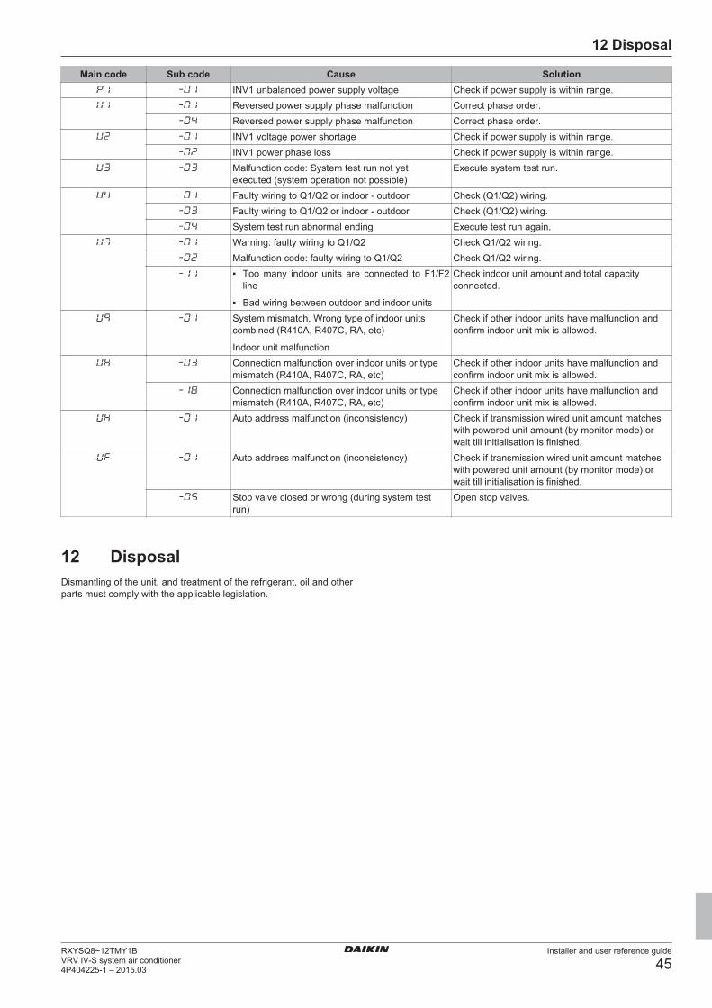
12 Disposal
Installer and user reference guide
45RXYSQ8~12TMY1BVRV IV-S system air conditioner4P404225-1 – 2015.03
Main code Sub code Cause SolutionINV1 unbalanced power supply voltage Check if power supply is within range.Reversed power supply phase malfunction Correct phase order.Reversed power supply phase malfunction Correct phase order.INV1 voltage power shortage Check if power supply is within range.INV1 power phase loss Check if power supply is within range.Malfunction code: System test run not yetexecuted (system operation not possible)
Execute system test run.
Faulty wiring to Q1/Q2 or indoor - outdoor Check (Q1/Q2) wiring.Faulty wiring to Q1/Q2 or indoor - outdoor Check (Q1/Q2) wiring.System test run abnormal ending Execute test run again.Warning: faulty wiring to Q1/Q2 Check Q1/Q2 wiring.Malfunction code: faulty wiring to Q1/Q2 Check Q1/Q2 wiring.▪ Too many indoor units are connected to F1/F2
line
▪ Bad wiring between outdoor and indoor units
Check indoor unit amount and total capacityconnected.
System mismatch. Wrong type of indoor unitscombined (R410A, R407C, RA, etc)
Indoor unit malfunction
Check if other indoor units have malfunction andconfirm indoor unit mix is allowed.
Connection malfunction over indoor units or typemismatch (R410A, R407C, RA, etc)
Check if other indoor units have malfunction andconfirm indoor unit mix is allowed.
Connection malfunction over indoor units or typemismatch (R410A, R407C, RA, etc)
Check if other indoor units have malfunction andconfirm indoor unit mix is allowed.
Auto address malfunction (inconsistency) Check if transmission wired unit amount matcheswith powered unit amount (by monitor mode) orwait till initialisation is finished.
Auto address malfunction (inconsistency) Check if transmission wired unit amount matcheswith powered unit amount (by monitor mode) orwait till initialisation is finished.
Stop valve closed or wrong (during system testrun)
Open stop valves.
12 DisposalDismantling of the unit, and treatment of the refrigerant, oil and otherparts must comply with the applicable legislation.
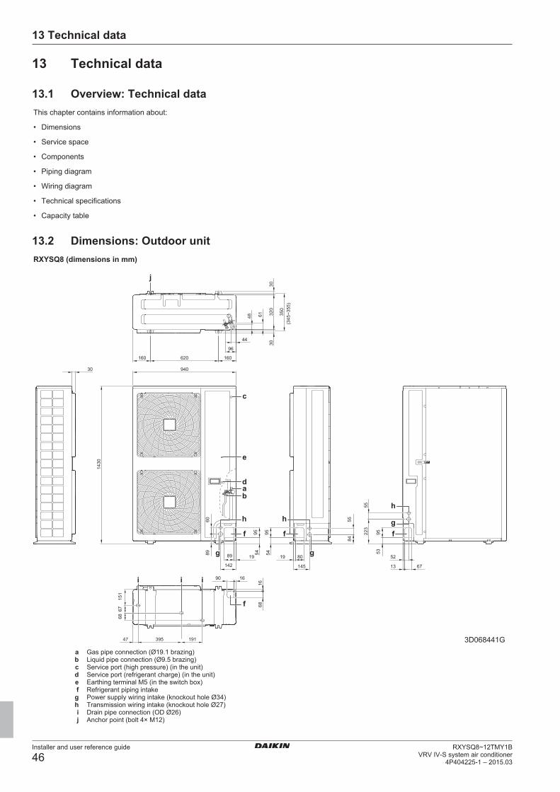
13 Technical data
Installer and user reference guide
46RXYSQ8~12TMY1B
VRV IV-S system air conditioner4P404225-1 – 2015.03
13 Technical data
13.1 Overview: Technical dataThis chapter contains information about:
• Dimensions
• Service space
• Components
• Piping diagram
• Wiring diagram
• Technical specifications
• Capacity table
13.2 Dimensions: Outdoor unitRXYSQ8 (dimensions in mm)
191
142
67
95
94022
3
30
16
55
350
160
9561
55
145
160
30
68
89
84
68
19
48
44
53
90
13 67
80
54
39547
52
1430
54
95
60
320
89
620
151
19
16
96
30
(345
~355
)
h hh
3D068441G
f
f
g g
fgf
bad
e
c
i i
j
i
a Gas pipe connection (Ø19.1 brazing)b Liquid pipe connection (Ø9.5 brazing)c Service port (high pressure) (in the unit)d Service port (refrigerant charge) (in the unit)e Earthing terminal M5 (in the switch box)f Refrigerant piping intakeg Power supply wiring intake (knockout hole Ø34)h Transmission wiring intake (knockout hole Ø27)i Drain pipe connection (OD Ø26)j Anchor point (bolt 4× M12)
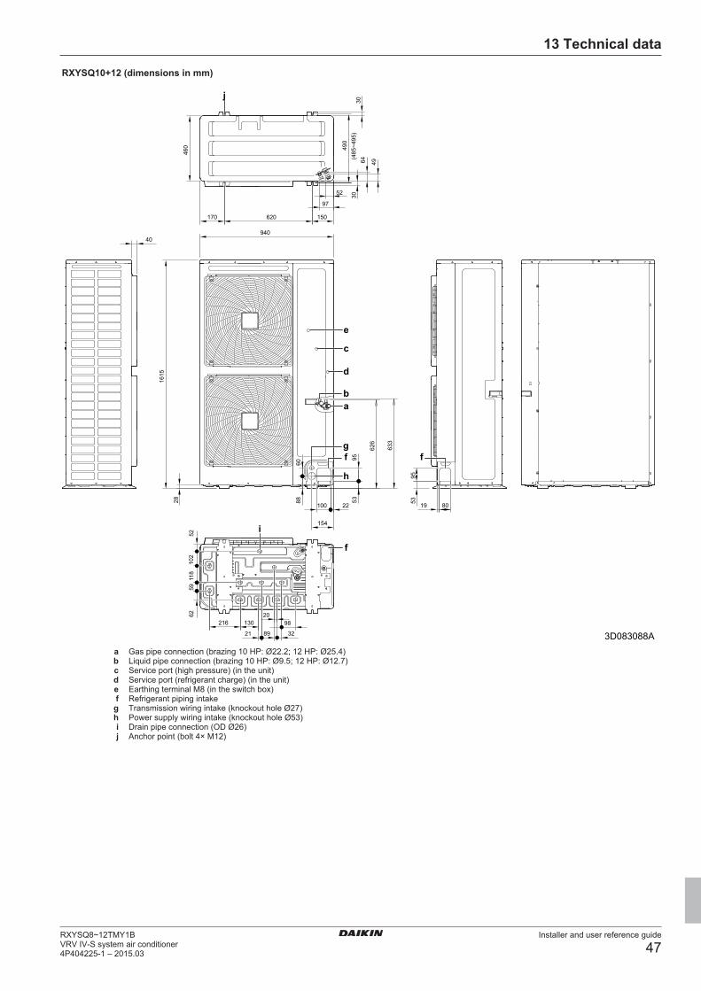
13 Technical data
Installer and user reference guide
47RXYSQ8~12TMY1BVRV IV-S system air conditioner4P404225-1 – 2015.03
RXYSQ10+12 (dimensions in mm)
(485
~495
)49
030
460
40
30
97
52
4964
940
170 620 150
102
60
95
118
6259
216 130
21
20
32
52
1615
28 88
100
154
53
22
98
8019
9553
626
633
89 3D083088A
f fg
ab
d
h
f
c
e
i
j
a Gas pipe connection (brazing 10 HP: Ø22.2; 12 HP: Ø25.4)b Liquid pipe connection (brazing 10 HP: Ø9.5; 12 HP: Ø12.7)c Service port (high pressure) (in the unit)d Service port (refrigerant charge) (in the unit)e Earthing terminal M8 (in the switch box)f Refrigerant piping intakeg Transmission wiring intake (knockout hole Ø27)h Power supply wiring intake (knockout hole Ø53)i Drain pipe connection (OD Ø26)j Anchor point (bolt 4× M12)
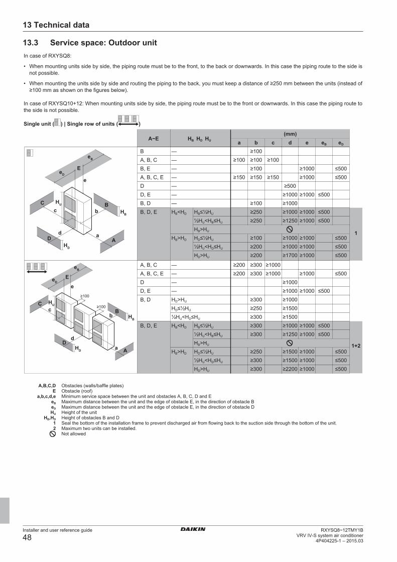
13 Technical data
Installer and user reference guide
48RXYSQ8~12TMY1B
VRV IV-S system air conditioner4P404225-1 – 2015.03
13.3 Service space: Outdoor unitIn case of RXYSQ8:
• When mounting units side by side, the piping route must be to the front, to the back or downwards. In this case the piping route to the side isnot possible.
• When mounting the units side by side and routing the piping to the back, you must keep a distance of ≥250 mm between the units (instead of≥100 mm as shown on the figures below).
In case of RXYSQ10+12: When mounting units side by side, the piping route must be to the front or downwards. In this case the piping route tothe side is not possible.
Single unit ( ) | Single row of units ( )
1+2
1
A~Ea b c d e eB eD
HB HD HU
(mm)
a
bc
d
e
eB
eD
A
BC
D
E
HB
HU
HD
B — ≥100A, B, C — ≥100 ≥100 ≥100B, E — ≥100 ≥1000 ≤500A, B, C, E — ≥150 ≥150 ≥150 ≥1000 ≤500D — ≥500D, E — ≥1000 ≥1000 ≤500B, D — ≥100 ≥1000B, D, E HB<HD HB≤½HU ≥250 ≥1000 ≥1000 ≤500
½HU<HB≤HU ≥250 ≥1250 ≥1000 ≤500HB>HU
HB>HD HD≤½HU ≥100 ≥1000 ≥1000 ≤500½HU<HD≤HU ≥200 ≥1000 ≥1000 ≤500HD>HU ≥200 ≥1700 ≥1000 ≤500
HU
a
b≥100
≥100
c
d
e
eB
eD
A
BC
D
E
HB
HD
A, B, C — ≥200 ≥300 ≥1000A, B, C, E — ≥200 ≥300 ≥1000 ≥1000 ≤500D — ≥1000D, E — ≥1000 ≥1000 ≤500B, D HD>HU ≥300 ≥1000
HD≤½HU ≥250 ≥1500½HU<HD≤HU ≥300 ≥1500
B, D, E HB<HD HB≤½HU ≥300 ≥1000 ≥1000 ≤500½HU<HB≤HU ≥300 ≥1250 ≥1000 ≤500HB>HU
HB>HD HD≤½HU ≥250 ≥1500 ≥1000 ≤500½HU<HD≤HU ≥300 ≥1500 ≥1000 ≤500HD>HU ≥300 ≥2200 ≥1000 ≤500
A,B,C,D Obstacles (walls/baffle plates)E Obstacle (roof)
a,b,c,d,e Minimum service space between the unit and obstacles A, B, C, D and EeB Maximum distance between the unit and the edge of obstacle E, in the direction of obstacle BeD Maximum distance between the unit and the edge of obstacle E, in the direction of obstacle DHU Height of the unit
HB,HD Height of obstacles B and D1 Seal the bottom of the installation frame to prevent discharged air from flowing back to the suction side through the bottom of the unit.2 Maximum two units can be installed.
Not allowed
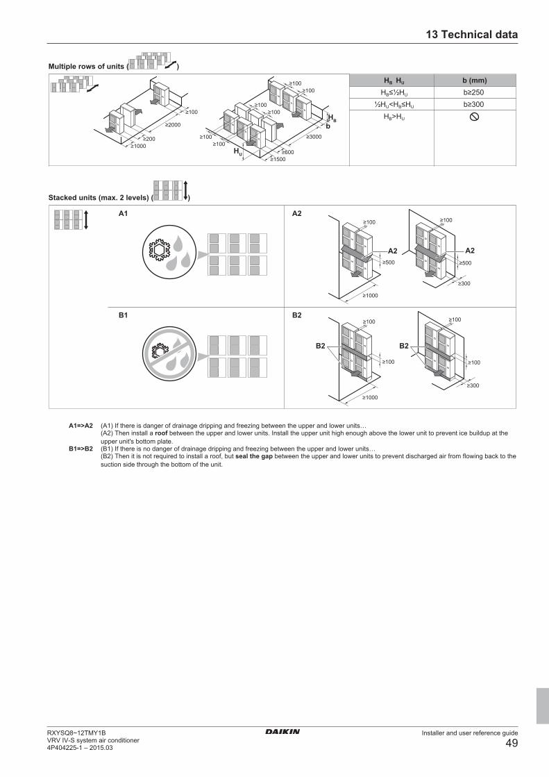
13 Technical data
Installer and user reference guide
49RXYSQ8~12TMY1BVRV IV-S system air conditioner4P404225-1 – 2015.03
Multiple rows of units ( )
b (mm)HB≤½HU b≥250
½HU<HB≤HU b≥300HB>HU
HB HU
≥1000≥200
≥2000
≥100
≥3000
≥600≥1500
b
≥100≥100
≥100≥100
≥100≥100
HB
HU
Stacked units (max. 2 levels) ( )
A1
B1
A2
B2
A2
≥1000
A2
≥300
≥100 ≥100
≥100
≥300
≥100 ≥100
B2
≥100
≥1000
B2
A1=>A2 (A1) If there is danger of drainage dripping and freezing between the upper and lower units…(A2) Then install a roof between the upper and lower units. Install the upper unit high enough above the lower unit to prevent ice buildup at theupper unit's bottom plate.
B1=>B2 (B1) If there is no danger of drainage dripping and freezing between the upper and lower units…(B2) Then it is not required to install a roof, but seal the gap between the upper and lower units to prevent discharged air from flowing back to thesuction side through the bottom of the unit.
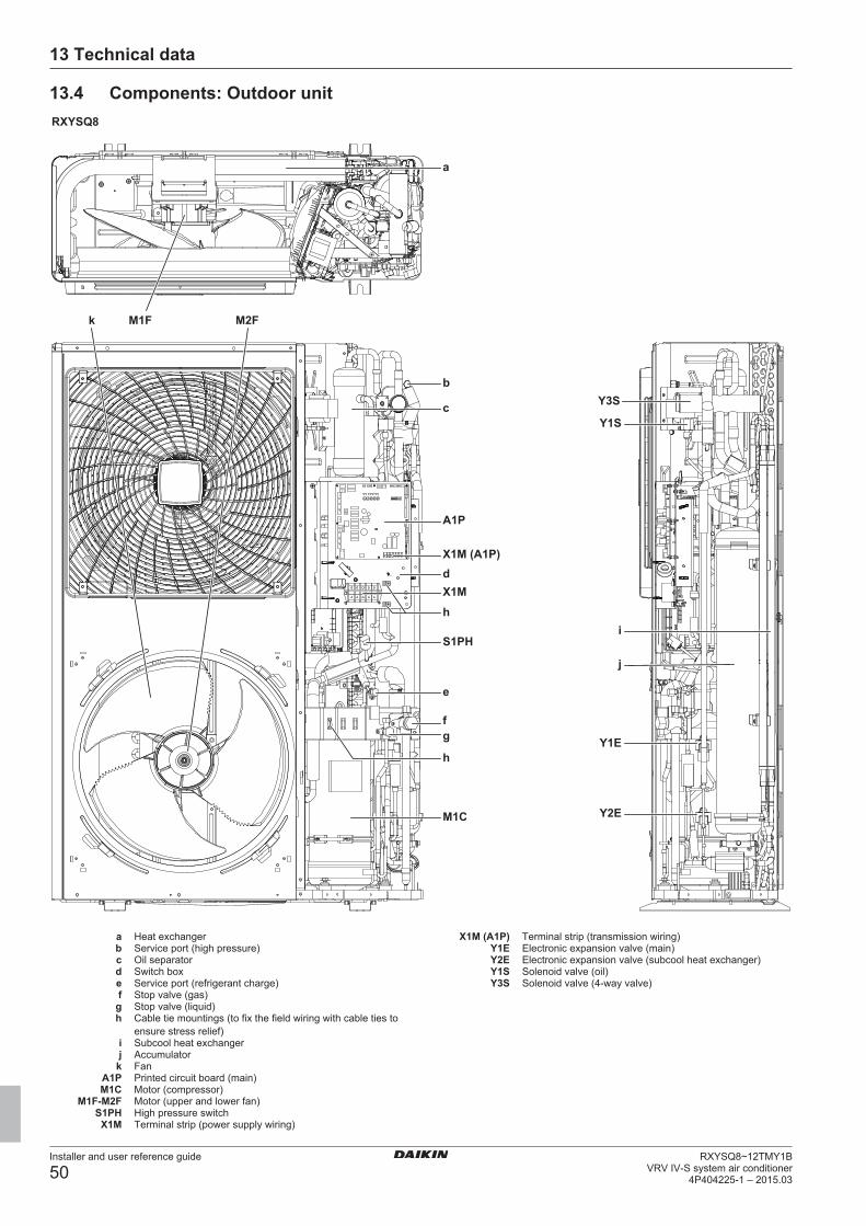
13 Technical data
Installer and user reference guide
50RXYSQ8~12TMY1B
VRV IV-S system air conditioner4P404225-1 – 2015.03
13.4 Components: Outdoor unitRXYSQ8
c
b
a
A1P
X1M (A1P)dX1M
S1PH
e
fg
h
M1C
h
Y3S
Y1S
i
j
Y2E
Y1E
M1Fk M2F
a Heat exchangerb Service port (high pressure)c Oil separatord Switch boxe Service port (refrigerant charge)f Stop valve (gas)g Stop valve (liquid)h Cable tie mountings (to fix the field wiring with cable ties to
ensure stress relief)i Subcool heat exchangerj Accumulator
k FanA1P Printed circuit board (main)M1C Motor (compressor)
M1F-M2F Motor (upper and lower fan)S1PH High pressure switch
X1M Terminal strip (power supply wiring)
X1M (A1P) Terminal strip (transmission wiring)Y1E Electronic expansion valve (main)Y2E Electronic expansion valve (subcool heat exchanger)Y1S Solenoid valve (oil)Y3S Solenoid valve (4‑way valve)
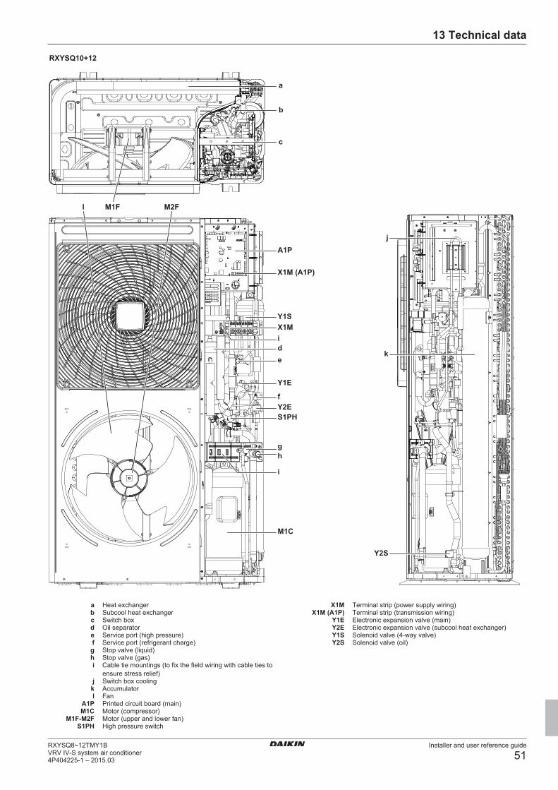
13 Technical data
Installer and user reference guide
51RXYSQ8~12TMY1BVRV IV-S system air conditioner4P404225-1 – 2015.03
RXYSQ10+12
b
c
l
A1P
X1M (A1P)
Y1SX1Mide
Y1E
fY2ES1PH
h
i
M1C
M2FM1F
a
j
k
Y2S
g
a Heat exchangerb Subcool heat exchangerc Switch boxd Oil separatore Service port (high pressure)f Service port (refrigerant charge)g Stop valve (liquid)h Stop valve (gas)i Cable tie mountings (to fix the field wiring with cable ties to
ensure stress relief)j Switch box cooling
k Accumulatorl Fan
A1P Printed circuit board (main)M1C Motor (compressor)
M1F-M2F Motor (upper and lower fan)S1PH High pressure switch
X1M Terminal strip (power supply wiring)X1M (A1P) Terminal strip (transmission wiring)
Y1E Electronic expansion valve (main)Y2E Electronic expansion valve (subcool heat exchanger)Y1S Solenoid valve (4‑way valve)Y2S Solenoid valve (oil)
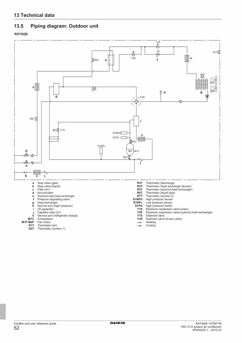
13 Technical data
Installer and user reference guide
52RXYSQ8~12TMY1B
VRV IV-S system air conditioner4P404225-1 – 2015.03
13.5 Piping diagram: Outdoor unitRXYSQ8
R6T
a
b
k c j
c
c
c
d
e f
gh
i
j
Y1S
S1NPL
S1NPH
S1PH
INV M1C
Y3S
Y2E
Y1E
M1F
M2FR7T
R5T
R2T
R3T
R4T
R1T
a Stop valve (gas)b Stop valve (liquid)c Filter (4×)d Accumulatore Subcool tube heat exchangerf Pressure regulating valveg Heat exchangerh Service port (high pressure)i Oil separatorj Capillary tube (2×)
k Service port (refrigerant charge)M1C Compressor
M1F-M2F Fan motorR1T Thermistor (air)R2T Thermistor (suction 1)
R3T Thermistor (discharge)R4T Thermistor (heat exchanger de-icer)R5T Thermistor (subcool heat exchanger)R6T Thermistor (liquid pipe)R7T Thermistor (suction 2)
S1NPH High pressure sensorS1NPL Low pressure sensor
S1PH High pressure switchY1E Electronic expansion valve (main)Y2E Electronic expansion valve (subcool heat exchanger)Y1S Solenoid valveY3S Solenoid valve (4‑way valve)
HeatingCooling
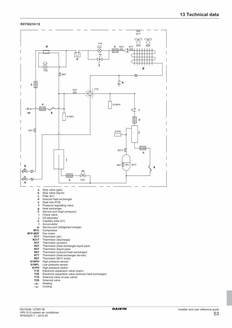
13 Technical data
Installer and user reference guide
53RXYSQ8~12TMY1BVRV IV-S system air conditioner4P404225-1 – 2015.03
RXYSQ10+12
R5T
R21T
R8T
R4T R7T
S1NPL
S1NPH
S1PH
INV M1C
Y2S
Y1S
Y1EM1F M2F
Y2E
R3T
R6T
R1T
a
l
m k
b
d
e
c
gf
h
i
c
j
k
c
c
c
c
a Stop valve (gas)b Stop valve (liquid)c Filter (6×)d Subcool heat exchangere Heat sink PCBf Pressure regulating valveg Heat exchangerh Service port (high pressure)i Check valvej Oil separator
k Capillary tube (2×)l Accumulator
m Service port (refrigerant charge)M1C Compressor
M1F-M2F Fan motorR1T Thermistor (air)
R21T Thermistor (discharge)R3T Thermistor (suction)R4T Thermistor (heat exchanger liquid pipe)R5T Thermistor (liquid pipe)R6T Thermistor (subcool heat exchanger)R7T Thermistor (heat exchanger de-icer)R8T Thermistor (M1C body)
S1NPH High pressure sensorS1NPL Low pressure sensor
S1PH High pressure switchY1E Electronic expansion valve (main)Y2E Electronic expansion valve (subcool heat exchanger)Y1S Solenoid valve (4‑way valve)Y2S Solenoid valve
HeatingCooling
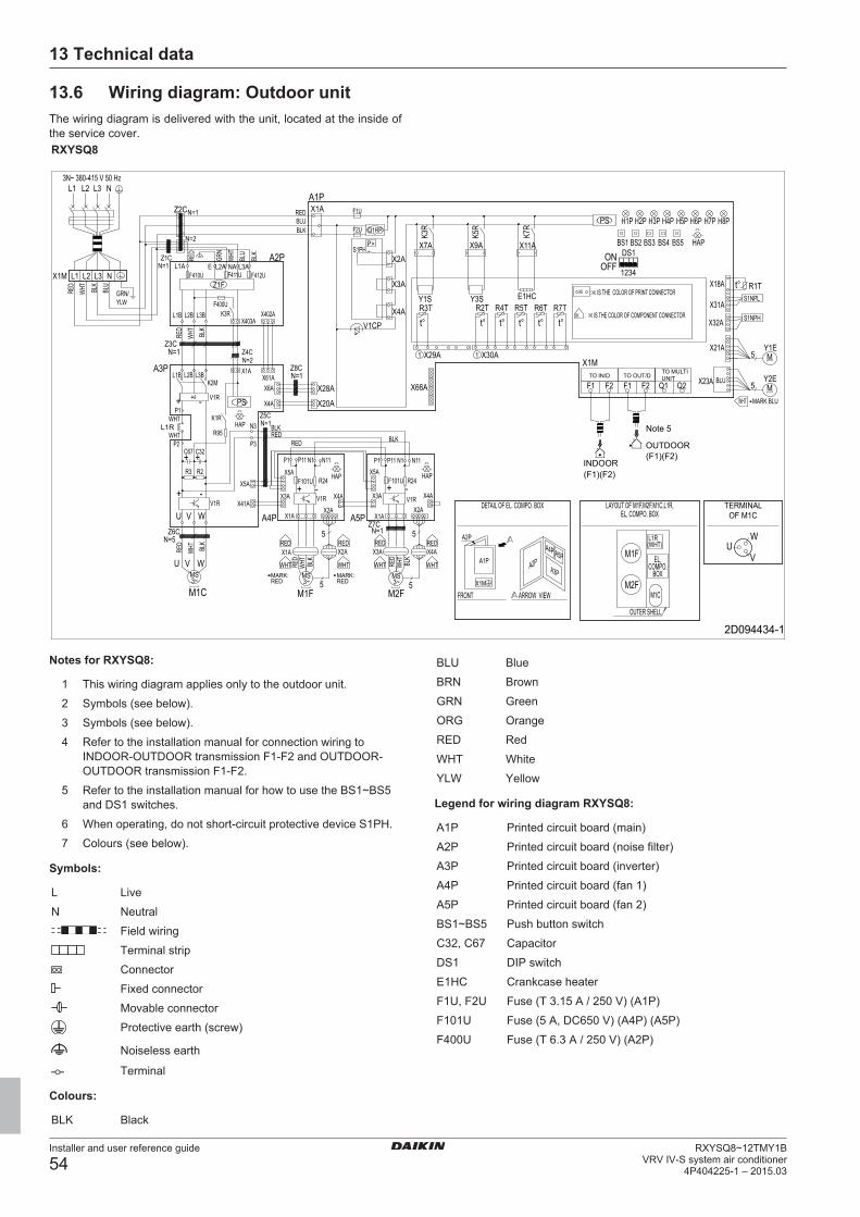
13 Technical data
Installer and user reference guide
54RXYSQ8~12TMY1B
VRV IV-S system air conditioner4P404225-1 – 2015.03
13.6 Wiring diagram: Outdoor unitThe wiring diagram is delivered with the unit, located at the inside ofthe service cover.RXYSQ8
3N~ 380-415 V 50 Hz
WHT
WHT
BLUBLK
RED
WHT
BLU
X1M
L1 L2 L3 N
L1
V1R V1R
V
WU
M2FM1C
M1F
X1M
A1PA3P
A4P A5PA2P
A2P
X1M
F1 Q2F2F1 Q1F2 X23AM
MY1E
Y2E5
5
R1T
S1NPH
S1NPLX31A
X21A
X32A
X18A
H5P H6PH4PH2P H8PH1P H3P
BS2 BS4BS3 HAPBS1 BS5DS1
1234OFFON
PS
E1HC
X11A
X30A
R5TR4TR2T
X1AA1P
F1U
R3TY3S
X9A
Y1S
K3R
K5RF2U Q1RP
S1PHP>
X2A
X3A
X4AV1CP
1 1X29A
X66A
P1 N11N1P11X5A
X4A
X4A
5M2F
5
X2A
F101U R24+ -
X3A
X1AA5PN=1
X3AX2A
5
5M1FM1C
WVU
N=5Z6C
X1A
X2A
X4AV1R+ -F101U R24
N11P1 N1P11
X5A
X3A
X1AA4P
X5A
X41A
V WU
-+
R2R3
P2
++C32
P3
N3
N=1Z8C
N=1Z5C
X20A
X28A
X4A
R95
K1RP1
L1R
-+ PS
K2ML3BL1B L2B
X6AX61A
X1AA3P
N=1Z3C
X402AX403A
K3RL3BL1B L2BF400U
NAL1A L3AE L2AA2P
NL2 L3
Z2C
Z4CN=2
Z1C
N=2
N=1
N=1
(F1)(F2)
Z1FF410U F411U F412U
Z7C
V1R
HAP
MS
C67
R6T R7T
H7P
X7A
K7R
HAP HAP
RED
WHT
BLK
RED
WHT
BLK
WHT
REDL1R(WHT)
RED
WHT
BLK
REDREDBLK
BLK
RED
WHT
BLK
RED
WHT
BLK
BLU
GRN/YLW
BLK
BLU
WHT
RED
GRN
2D094434-1
t° t° t° t° t° t°
t°
(F1)(F2)
3~MS3~
MS3~
WHT
RED
WHT
RED
WHT
RED
TO MULTI UNITTO OUT/DTO IN/D
INDOOR
OUTDOOR
Note 5
TERMINAL OF M1C
LAYOUT OF M1F,M2F,M1C,L1R,EL, COMPO. BOX
DETAIL OF EL. COMPO. BOX
ARROW VIEW
OUTER SHELL
FRONT
MARK:BLU
MARK:RED
MARK:RED
EL, COMPO.
BOX
IS THE COLOR OF COMPONENT CONNECTOR
IS THE COLOR OF PRINT CONNECTOR
Notes for RXYSQ8:
1 This wiring diagram applies only to the outdoor unit.
2 Symbols (see below).
3 Symbols (see below).
4 Refer to the installation manual for connection wiring toINDOOR-OUTDOOR transmission F1-F2 and OUTDOOR-OUTDOOR transmission F1-F2.
5 Refer to the installation manual for how to use the BS1~BS5and DS1 switches.
6 When operating, do not short-circuit protective device S1PH.
7 Colours (see below).
Symbols:
L Live
N Neutral
Field wiring
Terminal strip
Connector
Fixed connector
Movable connector
Protective earth (screw)
Noiseless earth
Terminal
Colours:
BLK Black
BLU Blue
BRN Brown
GRN Green
ORG Orange
RED Red
WHT White
YLW Yellow
Legend for wiring diagram RXYSQ8:
A1P Printed circuit board (main)
A2P Printed circuit board (noise filter)
A3P Printed circuit board (inverter)
A4P Printed circuit board (fan 1)
A5P Printed circuit board (fan 2)
BS1~BS5 Push button switch
C32, C67 Capacitor
DS1 DIP switch
E1HC Crankcase heater
F1U, F2U Fuse (T 3.15 A / 250 V) (A1P)
F101U Fuse (5 A, DC650 V) (A4P) (A5P)
F400U Fuse (T 6.3 A / 250 V) (A2P)
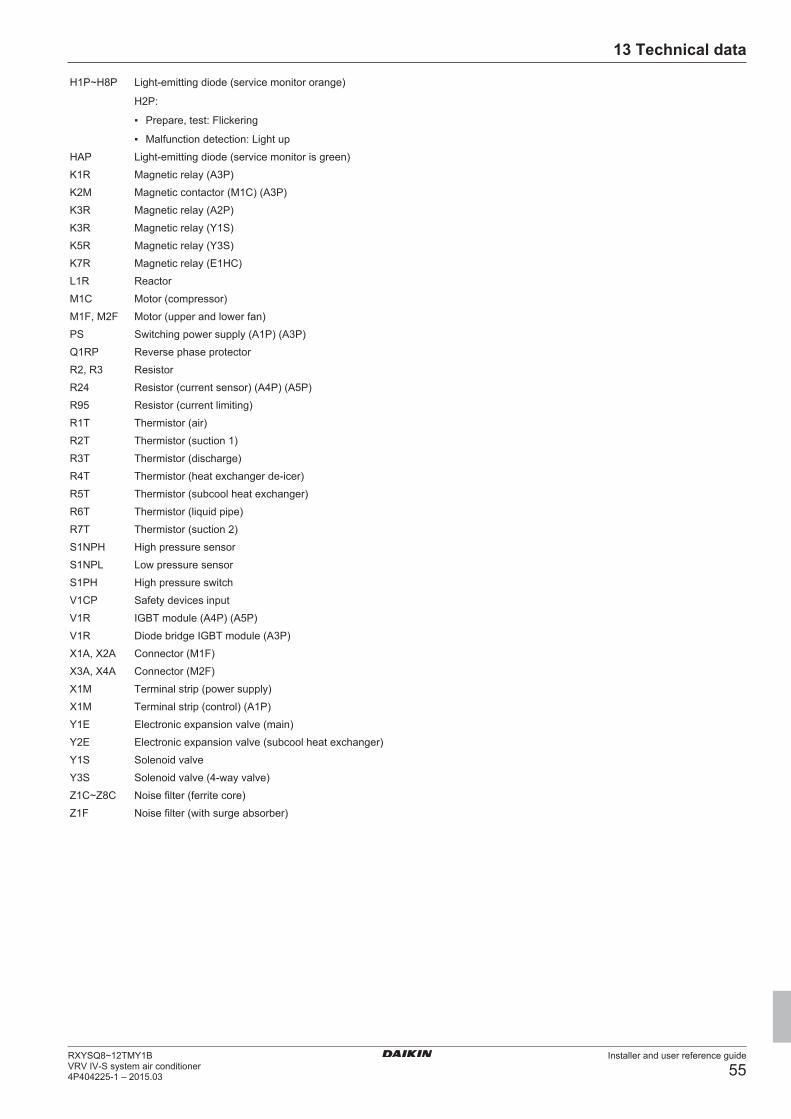
13 Technical data
Installer and user reference guide
55RXYSQ8~12TMY1BVRV IV-S system air conditioner4P404225-1 – 2015.03
H1P~H8P Light‑emitting diode (service monitor orange)
H2P:
▪ Prepare, test: Flickering
▪ Malfunction detection: Light up
HAP Light-emitting diode (service monitor is green)
K1R Magnetic relay (A3P)
K2M Magnetic contactor (M1C) (A3P)
K3R Magnetic relay (A2P)
K3R Magnetic relay (Y1S)
K5R Magnetic relay (Y3S)
K7R Magnetic relay (E1HC)
L1R Reactor
M1C Motor (compressor)
M1F, M2F Motor (upper and lower fan)
PS Switching power supply (A1P) (A3P)
Q1RP Reverse phase protector
R2, R3 Resistor
R24 Resistor (current sensor) (A4P) (A5P)
R95 Resistor (current limiting)
R1T Thermistor (air)
R2T Thermistor (suction 1)
R3T Thermistor (discharge)
R4T Thermistor (heat exchanger de-icer)
R5T Thermistor (subcool heat exchanger)
R6T Thermistor (liquid pipe)
R7T Thermistor (suction 2)
S1NPH High pressure sensor
S1NPL Low pressure sensor
S1PH High pressure switch
V1CP Safety devices input
V1R IGBT module (A4P) (A5P)
V1R Diode bridge IGBT module (A3P)
X1A, X2A Connector (M1F)
X3A, X4A Connector (M2F)
X1M Terminal strip (power supply)
X1M Terminal strip (control) (A1P)
Y1E Electronic expansion valve (main)
Y2E Electronic expansion valve (subcool heat exchanger)
Y1S Solenoid valve
Y3S Solenoid valve (4‑way valve)
Z1C~Z8C Noise filter (ferrite core)
Z1F Noise filter (with surge absorber)
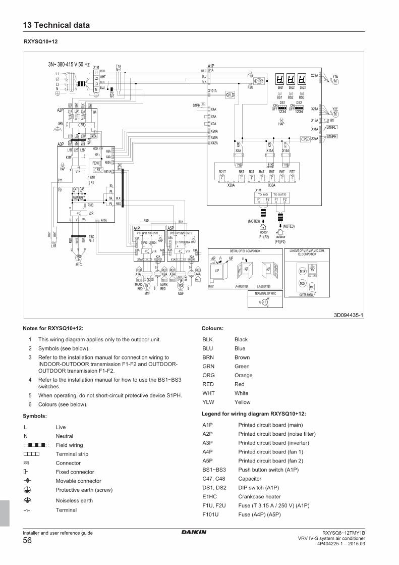
13 Technical data
Installer and user reference guide
56RXYSQ8~12TMY1B
VRV IV-S system air conditioner4P404225-1 – 2015.03
RXYSQ10+12
A2P
NA
M
A3P
L2B
Y1EF4
12U
A3P
HAP
1234 1234
A1P
BLU
Q1RPBLK
M2F
3N~ 380-415 V 50 Hz
N
N11
5
V2R
K11R
WHT
X32A
5
S1NPH
P21
+F4
10U
K4R
R7T
+
X2A
X4A
K7R
F1
HAP
N=1
U
Y2S
5X3A
BLK
V
N1Z3CN=1
5
W
X1A
R313
M2F
R1T
WHT
L2
N11
RED
W
R21T
P5N4R865
N
Z4CN=1
A2PA3P
M1C
BS2
BLKL3
P11
BS1
N1
S1NPL
RED
F2
L2A
X2A
ONOFF
V1R
(F1)(F2)
X42A
M
L1R
F2
X2A
HAP
X3A
BLK
X8A
L2BLK
R24
P>
+BL
K
X1A
(F1)(F2)
T1A
A2PA4PA5PL1R
L3A
RED
Y1S
V1R
X1M
R867
WHTX1M
X11A
WHT
HAP
S1PH
X1A
X23A
P11
X3A
L3
F1
C48
K3R
R6T
BLU
F411
UWH
T
M1F
t°
BLK
R24
N5
A1P
V
RED
SEG2
L3B
PS
L1
X3A
K1M
X4A
E
F101U
R3T
X5A
F601U
A2P
BLU
-
SEG3
X63A
L1B
5
F2U
V
-
Z1CN=1
SEG1
E1HC
RED
R4T
X21A
P4
Z1F
A5P
M1F
L1B
+
GRNX31A
C47
L1A
WHT DS1
M1C
X6A
X1M
P1
K1R
-
X1A
Y2E
U
W
PS
P11
F1U
R5T
BLK
RED
RED
L1
RED
X2A
L3B
t°
X101A
X5A
R1
DS2
Z2CN=1
+
X403A
Q1LD
X15A
U
X29A
RED
P1A4P
WHT
X20A
-
X602A
X4A
WHT
X41A
ONOFF
RED
BS3
F101U
X601A
V1R
X28A
X4A
5
+
X18A
X30A
WHT
RED
WHT
RED
WHT
RED
X4A
WHT
L2BBLK
R8Tt° t° t° t° t°t°
MS3~
3D094435-1
MS3~
MS3~
TO OUT/DTO IN/D
TERMINAL OF M1C
DETAIL OF El. COMPO BOX LAYOUT OF M1F,M2F,M1C,X1M,EL.COMPO.BOX
OUTER SHELL
EL.COMPO.
BOX
MARK:RED
MARK:RED
outdoorindoor
FRONT ARROW VIEW ARROW VIEW
(NOTE3)(NOTE3)
Notes for RXYSQ10+12:
1 This wiring diagram applies only to the outdoor unit.
2 Symbols (see below).
3 Refer to the installation manual for connection wiring toINDOOR-OUTDOOR transmission F1-F2 and OUTDOOR-OUTDOOR transmission F1-F2.
4 Refer to the installation manual for how to use the BS1~BS3switches.
5 When operating, do not short-circuit protective device S1PH.
6 Colours (see below).
Symbols:
L Live
N Neutral
Field wiring
Terminal strip
Connector
Fixed connector
Movable connector
Protective earth (screw)
Noiseless earth
Terminal
Colours:
BLK Black
BLU Blue
BRN Brown
GRN Green
ORG Orange
RED Red
WHT White
YLW Yellow
Legend for wiring diagram RXYSQ10+12:
A1P Printed circuit board (main)
A2P Printed circuit board (noise filter)
A3P Printed circuit board (inverter)
A4P Printed circuit board (fan 1)
A5P Printed circuit board (fan 2)
BS1~BS3 Push button switch (A1P)
C47, C48 Capacitor
DS1, DS2 DIP switch (A1P)
E1HC Crankcase heater
F1U, F2U Fuse (T 3.15 A / 250 V) (A1P)
F101U Fuse (A4P) (A5P)
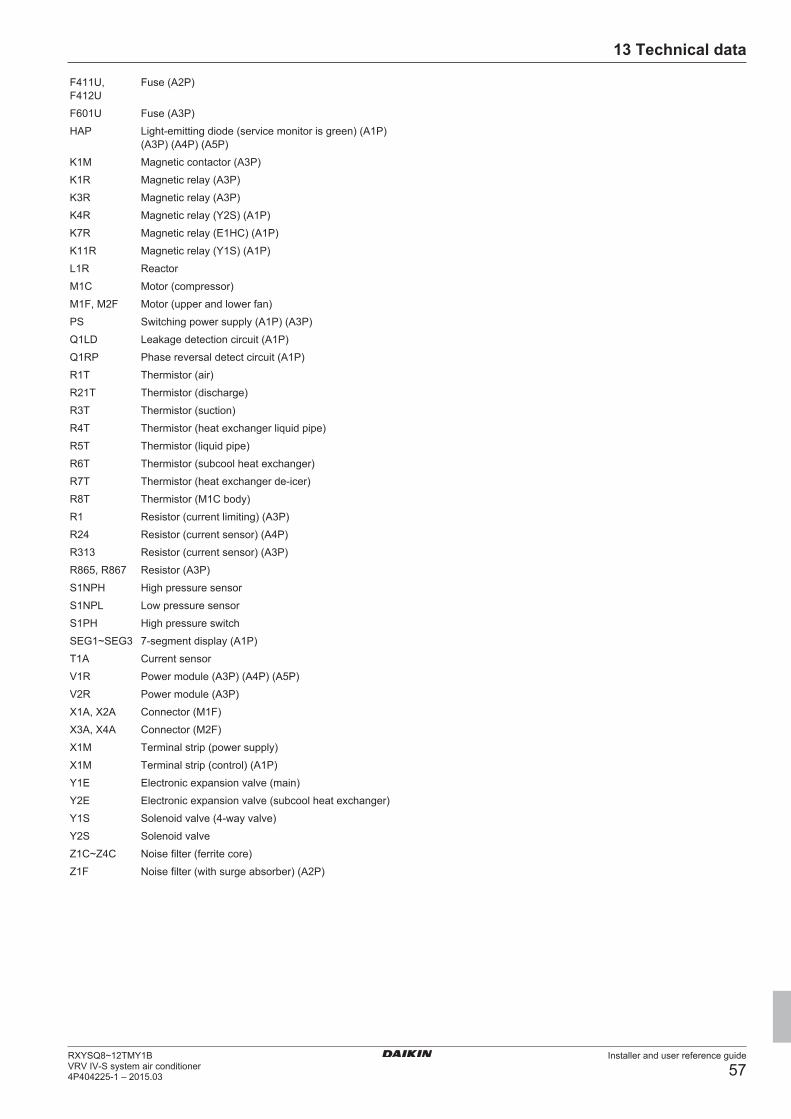
13 Technical data
Installer and user reference guide
57RXYSQ8~12TMY1BVRV IV-S system air conditioner4P404225-1 – 2015.03
F411U,F412U
Fuse (A2P)
F601U Fuse (A3P)
HAP Light-emitting diode (service monitor is green) (A1P)(A3P) (A4P) (A5P)
K1M Magnetic contactor (A3P)
K1R Magnetic relay (A3P)
K3R Magnetic relay (A3P)
K4R Magnetic relay (Y2S) (A1P)
K7R Magnetic relay (E1HC) (A1P)
K11R Magnetic relay (Y1S) (A1P)
L1R Reactor
M1C Motor (compressor)
M1F, M2F Motor (upper and lower fan)
PS Switching power supply (A1P) (A3P)
Q1LD Leakage detection circuit (A1P)
Q1RP Phase reversal detect circuit (A1P)
R1T Thermistor (air)
R21T Thermistor (discharge)
R3T Thermistor (suction)
R4T Thermistor (heat exchanger liquid pipe)
R5T Thermistor (liquid pipe)
R6T Thermistor (subcool heat exchanger)
R7T Thermistor (heat exchanger de-icer)
R8T Thermistor (M1C body)
R1 Resistor (current limiting) (A3P)
R24 Resistor (current sensor) (A4P)
R313 Resistor (current sensor) (A3P)
R865, R867 Resistor (A3P)
S1NPH High pressure sensor
S1NPL Low pressure sensor
S1PH High pressure switch
SEG1~SEG3 7-segment display (A1P)
T1A Current sensor
V1R Power module (A3P) (A4P) (A5P)
V2R Power module (A3P)
X1A, X2A Connector (M1F)
X3A, X4A Connector (M2F)
X1M Terminal strip (power supply)
X1M Terminal strip (control) (A1P)
Y1E Electronic expansion valve (main)
Y2E Electronic expansion valve (subcool heat exchanger)
Y1S Solenoid valve (4‑way valve)
Y2S Solenoid valve
Z1C~Z4C Noise filter (ferrite core)
Z1F Noise filter (with surge absorber) (A2P)
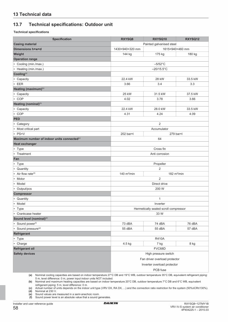
13 Technical data
Installer and user reference guide
58RXYSQ8~12TMY1B
VRV IV-S system air conditioner4P404225-1 – 2015.03
13.7 Technical specifications: Outdoor unitTechnical specifications
Specification RXYSQ8 RXYSQ10 RXYSQ12Casing material Painted galvanised steelDimensions h×w×d 1430×940×320 mm 1615×940×460 mmWeight 144 kg 175 kg 180 kgOperation range▪ Cooling (min./max.) –5/52°C▪ Heating (min./max.) –20/15.5°CCooling(a)
▪ Capacity 22.4 kW 28 kW 33.5 kW▪ EER 3.66 3.4 3.3Heating (maximum)(b)
▪ Capacity 25 kW 31.5 kW 37.5 kW▪ COP 4.02 3.78 3.66Heating (nominal)(b)
▪ Capacity 22.4 kW 28.0 kW 33.5 kW▪ COP 4.31 4.24 4.09PED▪ Category 2▪ Most critical part Accumulator▪ PS×V 202 bar×l 279 bar×lMaximum number of indoor units connected(c) 64Heat exchanger▪ Type Cross fin▪ Treatment Anti corrosionFan▪ Type Propeller▪ Quantity 2▪ Air flow rate(d) 140 m³/min 182 m³/min▪ Motor 2▪ Model Direct drive▪ Output/pcs 200 WCompressor▪ Quantity 1▪ Model Inverter▪ Type Hermetically sealed scroll compressor▪ Crankcase heater 33 WSound level (nominal)(e)
▪ Sound power(f) 73 dBA 74 dBA 76 dBA▪ Sound pressure(g) 55 dBA 55 dBA 57 dBARefrigerant▪ Type R410A▪ Charge 4.5 kg 7 kg 8 kgRefrigerant oil FVC68DSafety devices High pressure switch
Fan driver overload protector
Inverter overload protector
PCB fuse(a) Nominal cooling capacities are based on indoor temperature 27°C DB and 19°C WB, outdoor temperature 35°C DB, equivalent refrigerant piping:
5 m, level difference: 0 m, power input indoor units NOT included.(b) Nominal and maximum heating capacities are based on indoor temperature 20°C DB, outdoor temperature 7°C DB and 6°C WB, equivalent
refrigerant piping: 5 m, level difference: 0 m.(c) Actual number of units depends on the indoor unit type (VRV DX, RA DX, ...) and the connection ratio restriction for the system (50%≤CR≤130%).(d) Nominal at 230 V.(e) Sound values are measured in a semi-anechoic room.(f) Sound power level is an absolute value that a sound generates.
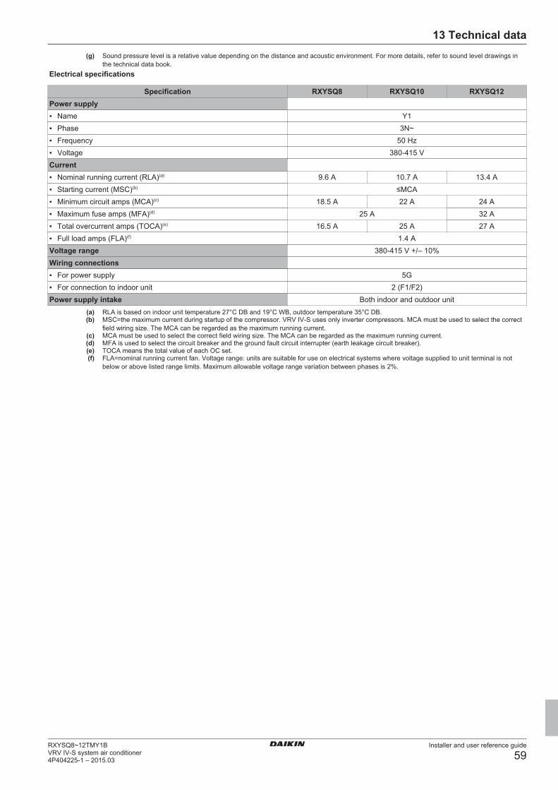
13 Technical data
Installer and user reference guide
59RXYSQ8~12TMY1BVRV IV-S system air conditioner4P404225-1 – 2015.03
(g) Sound pressure level is a relative value depending on the distance and acoustic environment. For more details, refer to sound level drawings inthe technical data book.
Electrical specifications
Specification RXYSQ8 RXYSQ10 RXYSQ12Power supply▪ Name Y1▪ Phase 3N~▪ Frequency 50 Hz▪ Voltage 380-415 VCurrent▪ Nominal running current (RLA)(a) 9.6 A 10.7 A 13.4 A▪ Starting current (MSC)(b) ≤MCA▪ Minimum circuit amps (MCA)(c) 18.5 A 22 A 24 A▪ Maximum fuse amps (MFA)(d) 25 A 32 A▪ Total overcurrent amps (TOCA)(e) 16.5 A 25 A 27 A▪ Full load amps (FLA)(f) 1.4 AVoltage range 380-415 V +/– 10%Wiring connections▪ For power supply 5G▪ For connection to indoor unit 2 (F1/F2)Power supply intake Both indoor and outdoor unit
(a) RLA is based on indoor unit temperature 27°C DB and 19°C WB, outdoor temperature 35°C DB.(b) MSC=the maximum current during startup of the compressor. VRV IV-S uses only inverter compressors. MCA must be used to select the correct
field wiring size. The MCA can be regarded as the maximum running current.(c) MCA must be used to select the correct field wiring size. The MCA can be regarded as the maximum running current.(d) MFA is used to select the circuit breaker and the ground fault circuit interrupter (earth leakage circuit breaker).(e) TOCA means the total value of each OC set.(f) FLA=nominal running current fan. Voltage range: units are suitable for use on electrical systems where voltage supplied to unit terminal is not
below or above listed range limits. Maximum allowable voltage range variation between phases is 2%.
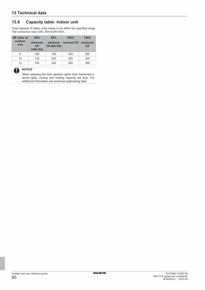
13 Technical data
Installer and user reference guide
60RXYSQ8~12TMY1B
VRV IV-S system air conditioner4P404225-1 – 2015.03
13.8 Capacity table: Indoor unitTotal capacity of indoor units needs to be within the specified range.The connection ratio (CR): 50%≤CR≤130%.
HP class ofoutdoor
unit
50%
minimumCR
(VRV DX)
80%
minimumCR (RA DX)
100%
nominal CR
130%
maximumCR
8 100 160 200 26010 125 200 250 32512 150 240 300 390
NOTICE
When selecting the total capacity higher than mentioned inabove table, cooling and heating capacity will drop. Foradditional information see technical engineering data.
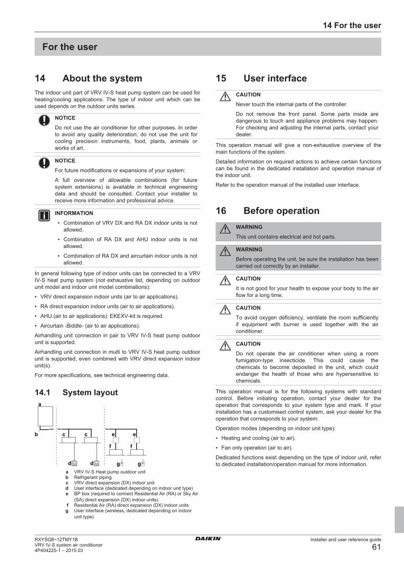
14 For the user
Installer and user reference guide
61RXYSQ8~12TMY1BVRV IV-S system air conditioner4P404225-1 – 2015.03
For the user
14 About the systemThe indoor unit part of VRV IV-S heat pump system can be used forheating/cooling applications. The type of indoor unit which can beused depends on the outdoor units series.
NOTICE
Do not use the air conditioner for other purposes. In orderto avoid any quality deterioration, do not use the unit forcooling precision instruments, food, plants, animals orworks of art.
NOTICE
For future modifications or expansions of your system:
A full overview of allowable combinations (for futuresystem extensions) is available in technical engineeringdata and should be consulted. Contact your installer toreceive more information and professional advice.
INFORMATION
▪ Combination of VRV DX and RA DX indoor units is notallowed.
▪ Combination of RA DX and AHU indoor units is notallowed.
▪ Combination of RA DX and aircurtain indoor units is notallowed.
In general following type of indoor units can be connected to a VRVIV-S heat pump system (not exhaustive list, depending on outdoorunit model and indoor unit model combinations):
▪ VRV direct expansion indoor units (air to air applications).
▪ RA direct expansion indoor units (air to air applications).
▪ AHU (air to air applications): EKEXV-kit is required.
▪ Aircurtain -Biddle- (air to air applications).
Airhandling unit connection in pair to VRV IV-S heat pump outdoorunit is supported.
Airhandling unit connection in multi to VRV IV-S heat pump outdoorunit is supported, even combined with VRV direct expansion indoorunit(s).
For more specifications, see technical engineering data.
14.1 System layout
gd d
c c
f
eb
a
g
f
e
a VRV IV-S Heat pump outdoor unitb Refrigerant pipingc VRV direct expansion (DX) indoor unitd User interface (dedicated depending on indoor unit type)e BP box (required to connect Residential Air (RA) or Sky Air
(SA) direct expansion (DX) indoor units)f Residential Air (RA) direct expansion (DX) indoor unitsg User interface (wireless, dedicated depending on indoor
unit type)
15 User interfaceCAUTION
Never touch the internal parts of the controller.
Do not remove the front panel. Some parts inside aredangerous to touch and appliance problems may happen.For checking and adjusting the internal parts, contact yourdealer.
This operation manual will give a non-exhaustive overview of themain functions of the system.
Detailed information on required actions to achieve certain functionscan be found in the dedicated installation and operation manual ofthe indoor unit.
Refer to the operation manual of the installed user interface.
16 Before operationWARNING
This unit contains electrical and hot parts.
WARNING
Before operating the unit, be sure the installation has beencarried out correctly by an installer.
CAUTION
It is not good for your health to expose your body to the airflow for a long time.
CAUTION
To avoid oxygen deficiency, ventilate the room sufficientlyif equipment with burner is used together with the airconditioner.
CAUTION
Do not operate the air conditioner when using a roomfumigation-type insecticide. This could cause thechemicals to become deposited in the unit, which couldendanger the health of those who are hypersensitive tochemicals.
This operation manual is for the following systems with standardcontrol. Before initiating operation, contact your dealer for theoperation that corresponds to your system type and mark. If yourinstallation has a customised control system, ask your dealer for theoperation that corresponds to your system.
Operation modes (depending on indoor unit type):
▪ Heating and cooling (air to air).
▪ Fan only operation (air to air).
Dedicated functions exist depending on the type of indoor unit, referto dedicated installation/operation manual for more information.
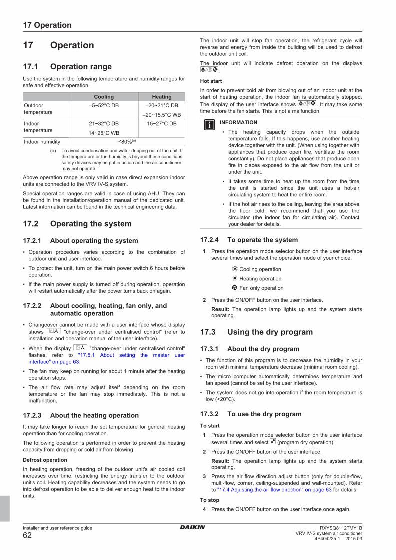
17 Operation
Installer and user reference guide
62RXYSQ8~12TMY1B
VRV IV-S system air conditioner4P404225-1 – 2015.03
17 Operation
17.1 Operation rangeUse the system in the following temperature and humidity ranges forsafe and effective operation.
Cooling HeatingOutdoortemperature
–5~52°C DB –20~21°C DB
–20~15.5°C WBIndoortemperature
21~32°C DB
14~25°C WB
15~27°C DB
Indoor humidity ≤80%(a)
(a) To avoid condensation and water dripping out of the unit. Ifthe temperature or the humidity is beyond these conditions,safety devices may be put in action and the air conditionermay not operate.
Above operation range is only valid in case direct expansion indoorunits are connected to the VRV IV-S system.
Special operation ranges are valid in case of using AHU. They canbe found in the installation/operation manual of the dedicated unit.Latest information can be found in the technical engineering data.
17.2 Operating the system
17.2.1 About operating the system▪ Operation procedure varies according to the combination of
outdoor unit and user interface.
▪ To protect the unit, turn on the main power switch 6 hours beforeoperation.
▪ If the main power supply is turned off during operation, operationwill restart automatically after the power turns back on again.
17.2.2 About cooling, heating, fan only, andautomatic operation
▪ Changeover cannot be made with a user interface whose displayshows "change-over under centralised control" (refer toinstallation and operation manual of the user interface).
▪ When the display "change-over under centralised control"flashes, refer to "17.5.1 About setting the master userinterface" on page 63.
▪ The fan may keep on running for about 1 minute after the heatingoperation stops.
▪ The air flow rate may adjust itself depending on the roomtemperature or the fan may stop immediately. This is not amalfunction.
17.2.3 About the heating operationIt may take longer to reach the set temperature for general heatingoperation than for cooling operation.
The following operation is performed in order to prevent the heatingcapacity from dropping or cold air from blowing.
Defrost operationIn heating operation, freezing of the outdoor unit's air cooled coilincreases over time, restricting the energy transfer to the outdoorunit's coil. Heating capability decreases and the system needs to gointo defrost operation to be able to deliver enough heat to the indoorunits:
The indoor unit will stop fan operation, the refrigerant cycle willreverse and energy from inside the building will be used to defrostthe outdoor unit coil.
The indoor unit will indicate defrost operation on the displays.
Hot startIn order to prevent cold air from blowing out of an indoor unit at thestart of heating operation, the indoor fan is automatically stopped.The display of the user interface shows . It may take sometime before the fan starts. This is not a malfunction.
INFORMATION
▪ The heating capacity drops when the outsidetemperature falls. If this happens, use another heatingdevice together with the unit. (When using together withappliances that produce open fire, ventilate the roomconstantly). Do not place appliances that produce openfire in places exposed to the air flow from the unit orunder the unit.
▪ It takes some time to heat up the room from the timethe unit is started since the unit uses a hot-aircirculating system to heat the entire room.
▪ If the hot air rises to the ceiling, leaving the area abovethe floor cold, we recommend that you use thecirculator (the indoor fan for circulating air). Contactyour dealer for details.
17.2.4 To operate the system1 Press the operation mode selector button on the user interface
several times and select the operation mode of your choice.
Cooling operation
Heating operation
Fan only operation
2 Press the ON/OFF button on the user interface.
Result: The operation lamp lights up and the system startsoperating.
17.3 Using the dry program
17.3.1 About the dry program▪ The function of this program is to decrease the humidity in your
room with minimal temperature decrease (minimal room cooling).
▪ The micro computer automatically determines temperature andfan speed (cannot be set by the user interface).
▪ The system does not go into operation if the room temperature islow (<20°C).
17.3.2 To use the dry programTo start1 Press the operation mode selector button on the user interface
several times and select (program dry operation).
2 Press the ON/OFF button of the user interface.
Result: The operation lamp lights up and the system startsoperating.
3 Press the air flow direction adjust button (only for double-flow,multi-flow, corner, ceiling-suspended and wall-mounted). Referto "17.4 Adjusting the air flow direction" on page 63 for details.
To stop4 Press the ON/OFF button on the user interface once again.
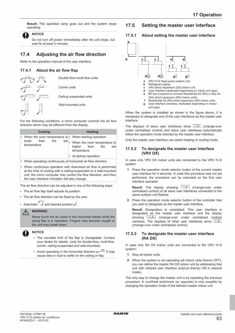
17 Operation
Installer and user reference guide
63RXYSQ8~12TMY1BVRV IV-S system air conditioner4P404225-1 – 2015.03
Result: The operation lamp goes out and the system stopsoperating.
NOTICE
Do not turn off power immediately after the unit stops, butwait for at least 5 minutes.
17.4 Adjusting the air flow directionRefer to the operation manual of the user interface.
17.4.1 About the air flow flap
Double flow+multi-flow units
Corner units
Ceiling suspended units
Wall-mounted units
For the following conditions, a micro computer controls the air flowdirection which may be different from the display.
Cooling Heating▪ When the room temperature is
lower than the settemperature.
▪ When starting operation.
▪ When the room temperature ishigher than the settemperature.
▪ At defrost operation.▪ When operating continuously at horizontal air flow direction.
▪ When continuous operation with downward air flow is performedat the time of cooling with a ceiling-suspended or a wall-mountedunit, the micro computer may control the flow direction, and thenthe user interface indication will also change.
The air flow direction can be adjusted in one of the following ways:
▪ The air flow flap itself adjusts its position.
▪ The air flow direction can be fixed by the user.
▪ Automatic and desired position .
WARNING
Never touch the air outlet or the horizontal blades while theswing flap is in operation. Fingers may become caught orthe unit may break down.
NOTICE
▪ The movable limit of the flap is changeable. Contactyour dealer for details. (only for double-flow, multi-flow,corner, ceiling-suspended and wall-mounted).
▪ Avoid operating in the horizontal direction . It maycause dew or dust to settle on the ceiling or flap.
17.5 Setting the master user interface
17.5.1 About setting the master user interface
gd d
c c
f
eb
a
g
f
e
a VRV IV-S Heat pump outdoor unitb Refrigerant pipingc VRV direct expansion (DX) indoor unitd User interface (dedicated depending on indoor unit type)e BP box (required to connect Residential Air (RA) or Sky Air
(SA) direct expansion (DX) indoor units)f Residential Air (RA) direct expansion (DX) indoor unitsg User interface (wireless, dedicated depending on indoor
unit type)
When the system is installed as shown in the figure above, it isnecessary to designate one of the user interfaces as the master userinterface.
The displays of slave user interfaces show (change-overunder centralised control) and slave user interfaces automaticallyfollow the operation mode directed by the master user interface.
Only the master user interface can select heating or cooling mode.
17.5.2 To designate the master user interface(VRV DX)
In case only VRV DX indoor units are connected to the VRV IV-Ssystem:
1 Press the operation mode selector button of the current masteruser interface for 4 seconds. In case this procedure was not yetperformed, the procedure can be executed on the first userinterface operated.
Result: The display showing (change-over undercentralised control) of all slave user interfaces connected to thesame outdoor unit flashes.
2 Press the operation mode selector button of the controller thatyou wish to designate as the master user interface.
Result: Designation is completed. This user interface isdesignated as the master user interface and the displayshowing (change-over under centralised control)vanishes. The displays of other user interfaces show (change-over under centralised control).
17.5.3 To designate the master user interface(RA DX)
In case only RA DX indoor units are connected to the VRV IV-Ssystem:
1 Stop all indoor units.
2 When the system is not operating (all indoor units thermo OFF),you can define the master RA DX indoor unit by addressing thatunit with infrared user interface (instruct thermo ON in desiredmode).
The only way to change the master unit is by repeating the previousprocedure. A cool/heat switchover (or opposite) is only possible bychanging the operation mode of the defined master indoor unit.
18 Energy saving and optimum operation
Installer and user reference guide
64RXYSQ8~12TMY1B
VRV IV-S system air conditioner4P404225-1 – 2015.03
17.5.4 About control systemsThis system provides two other control systems beside individualcontrol system (one user interface controls one indoor unit). Confirmthe following if your unit is of the following control system type:
Type DescriptionGroup control system One user interface controls up to 16
indoor units. All indoor units are equallyset.
Two user interface controlsystem
Two user interfaces control one indoorunit (in case of group control system,one group of indoor units). The unit isindividually operated.
NOTICE
Contact your dealer in case of changing the combination orsetting of group control and two user interface controlsystems.
18 Energy saving and optimumoperation
Observe the following precautions to ensure the system operatesproperly.
▪ Adjust the air outlet properly and avoid direct air flow to roominhabitants.
▪ Adjust the room temperature properly for a comfortableenvironment. Avoid excessive heating or cooling.
▪ Prevent direct sunlight from entering a room during coolingoperation by using curtains or blinds.
▪ Ventilate often. Extended use requires special attention toventilation.
▪ Keep doors and windows closed. If the doors and windows remainopen, air will flow out of your room causing a decrease in thecooling or heating effect.
▪ Be careful not to cool or heat too much. To save energy, keep thetemperature setting at a moderate level.
▪ Never place objects near the air inlet or the air outlet of the unit. Itmay cause deterioration in the effect or stop the operation.
▪ Turn off the main power supply switch to the unit when the unit isnot used for longer periods of time. If the switch is on, it consumeselectricity. Before restarting the unit, turn on the main powersupply switch 6 hours before operation to ensure smooth running.(Refer to "Maintenance" in the indoor unit manual.)
▪ When the display shows (time to clean the air filter), ask aqualified service person to clean the filters. (Refer to"Maintenance" in the indoor unit manual.)
▪ Keep the indoor unit and user interface at least 1 m away fromtelevisions, radios, stereos, and other similar equipment. Failing todo so may cause static or distorted pictures.
▪ Do not place items under the indoor unit, they may be damagedby water.
▪ Condensation may form if the humidity is above 80% or if thedrain outlet gets blocked.
This heat pump system is equipped with advanced energy savingfunctionality. Depending on the priority, emphasises can be put onenergy saving or comfort level. Several parameters can be selected,resulting in the optimal balance between energy consumption andcomfort for the particular application.
Several patterns are available and roughly explained below. Contactyour installer or dealer for advice or to modify the parameters to theneeds of your building.
Detailed information is given for the installer in the installationmanual. He can help you to realize the best balance between energyconsumption and comfort.
18.1 Available main operation methodsBasicThe refrigerant temperature is fixed independent from the situation. Itcorresponds to the standard operation which is known and can beexpected from/under previous VRV systems.
AutomaticThe refrigerant temperature is set depending on the outdoor ambientconditions. As such adjusting the refrigerant temperature to matchthe required load (which is also related to the outdoor ambientconditions).
E.g., when your system is operating in cooling, you do not need asmuch cooling under low outdoor ambient temperatures (e.g., 25°C)as under high outdoor ambient temperatures (e.g., 35°C). Using thisidea, the system automatically starts increasing its refrigeranttemperature, automatically reducing the delivered capacity andincreasing the system's efficiency.
Hi-sensible/economic (cooling/heating)The refrigerant temperature is set higher/lower (cooling/heating)compared to basic operation. The focus under high sensible mode iscomfort feeling for the customer.
The selection method of indoor units is important and has to beconsidered as the available capacity is not the same as under basicoperation.
For details concerning to Hi-sensible applications, please contactyour installer.
18.2 Available comfort settingsFor each of above modes a comfort level can be selected. Thecomfort level is related to the timing and the effort (energyconsumption) which is put in achieving a certain room temperatureby temporarily changing the refrigerant temperature to differentvalues in order to achieve requested conditions more quickly.
▪ Powerful
▪ Quick
▪ Mild
▪ Eco
19 Maintenance and serviceNOTICE
Never inspect or service the unit by yourself. Ask aqualified service person to perform this work.
WARNING
Never replace a fuse with a fuse of a wrong ampere ratingsor other wires when a fuse blows out. Use of wire orcopper wire may cause the unit to break down or cause afire.
CAUTION
Do not insert fingers, rods or other objects into the air inletor outlet. Do not remove the fan guard. When the fan isrotating at high speed, it will cause injury.
19 Maintenance and service
Installer and user reference guide
65RXYSQ8~12TMY1BVRV IV-S system air conditioner4P404225-1 – 2015.03
CAUTION
Pay attention to the fan.
It is dangerous to inspect the unit while the fan is running.
Be sure to turn off the main switch before executing anymaintenance task.
CAUTION
After a long use, check the unit stand and fitting fordamage. If damaged, the unit may fall and result in injury.
NOTICE
Do not wipe the controller operation panel with benzine,thinner, chemical dust cloth, etc. The panel may getdiscoloured or the coating peeled off. If it is heavily dirty,soak a cloth in water-diluted neutral detergent, squeeze itwell and wipe the panel clean. Wipe it with another drycloth.
19.1 Maintenance after a long stopperiod
E.g., at the beginning of the season.
▪ Check and remove everything that might be blocking inlet andoutlet vents of indoor units and outdoor units.
▪ Clean air filters and casings of indoor units. Contact your installeror maintenance person to clean air filters and casings of theindoor unit. Maintenance tips and procedures for cleaning areprovided in the installation/operation manuals of dedicated indoorunits. Make sure to install cleaned air filters back in the sameposition.
▪ Turn on the power at least 6 hours before operating the unit inorder to ensure smoother operation. As soon as the power isturned on, the user interface display appears.
19.2 Maintenance before a long stopperiod
E.g., at the end of the season.
▪ Let the indoor units run in fan only operation for about half a day inorder to dry the interior of the units. Refer to "17.2.2 Aboutcooling, heating, fan only, and automatic operation" on page 62for details on fan only operation.
▪ Turn off the power. The user interface display disappears.
▪ Clean air filters and casings of indoor units. Contact your installeror maintenance person to clean air filters and casings of theindoor unit. Maintenance tips and procedures for cleaning areprovided in the installation/operation manuals of dedicated indoorunits. Make sure to install cleaned air filters back in the sameposition.
19.3 About the refrigerantThis product contains fluorinated greenhouse gases. Do NOT ventgases into the atmosphere.
Refrigerant type: R410A
Global warming potential value: 2087.5
Periodical inspections for refrigerant leaks may be requireddepending on the applicable legislation. Please contact your installerfor more information.
WARNING
The refrigerant in the air conditioner is safe and normallydoes not leak. If the refrigerant leaks in the room, contactwith a fire of a burner, a heater or a cooker may result in aharmful gas.
Turn off any combustible heating devices, ventilate theroom and contact the dealer where you purchased the unit.
Do not use the air conditioner until a service personconfirms that the portion where the refrigerant leaks isrepaired.
19.4 After-sales service and warranty
19.4.1 Warranty period▪ This product includes a warranty card that was filled in by the
dealer at the time of installation. The completed card has to bechecked by the customer and stored carefully.
▪ If repairs to the air conditioner are necessary within the warrantyperiod, contact your dealer and keep the warranty card at hand.
19.4.2 Recommended maintenance andinspection
Since dust collects when using the unit for several years,performance of the unit will deteriorate to some extent. As takingapart and cleaning interiors of units requires technical expertise andin order to ensure the best possible maintenance of your units, werecommend to enter into a maintenance and inspection contract ontop of normal maintenance activities. Our network of dealers hasaccess to a permanent stock of essential components in order tokeep your air conditioner in operation as long as possible. Contactyour dealer for more information.
When asking your dealer for an intervention, always state:▪ The complete model name of the air conditioner.
▪ The manufacturing number (stated on the nameplate of the unit).
▪ The installation date.
▪ The symptoms or malfunction, and details of the defect.
WARNING
▪ Do not modify, disassemble, remove, reinstall or repairthe unit yourself as incorrect dismantling or installationmay cause an electric shock or fire. Contact yourdealer.
▪ In case of accidental refrigerant leaks, make sure thereare no naked flames. The refrigerant itself is entirelysafe, non-toxic and non-combustible, but it willgenerate toxic gas when it accidentally leaks into aroom where combustible air from fan heaters, gascookers, etc. is present. Always have qualified servicepersonnel confirm that the point of leakage has beenrepaired or corrected before resuming operation.
19.4.3 Recommended maintenance andinspection cycles
Be aware that the mentioned maintenance and replacement cyclesdo not relate to the warranty period of the components.
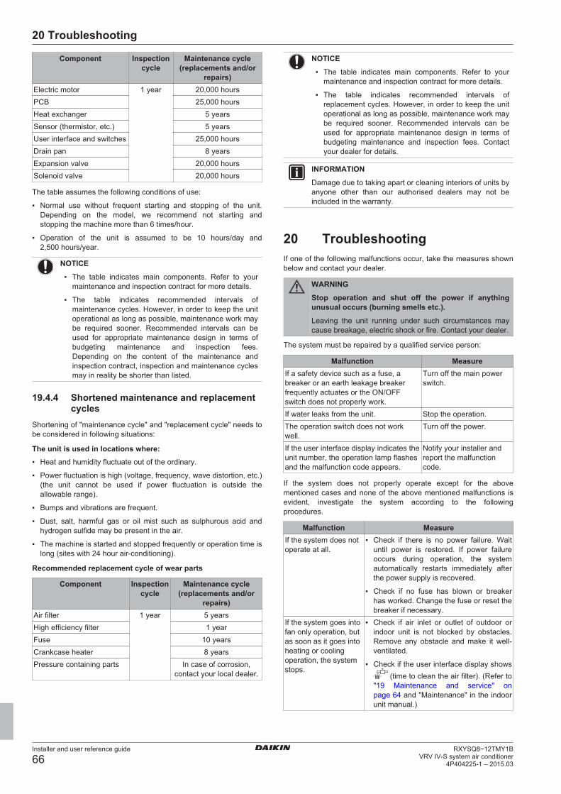
20 Troubleshooting
Installer and user reference guide
66RXYSQ8~12TMY1B
VRV IV-S system air conditioner4P404225-1 – 2015.03
Component Inspectioncycle
Maintenance cycle(replacements and/or
repairs)Electric motor 1 year 20,000 hoursPCB 25,000 hoursHeat exchanger 5 yearsSensor (thermistor, etc.) 5 yearsUser interface and switches 25,000 hoursDrain pan 8 yearsExpansion valve 20,000 hoursSolenoid valve 20,000 hours
The table assumes the following conditions of use:
▪ Normal use without frequent starting and stopping of the unit.Depending on the model, we recommend not starting andstopping the machine more than 6 times/hour.
▪ Operation of the unit is assumed to be 10 hours/day and2,500 hours/year.
NOTICE
▪ The table indicates main components. Refer to yourmaintenance and inspection contract for more details.
▪ The table indicates recommended intervals ofmaintenance cycles. However, in order to keep the unitoperational as long as possible, maintenance work maybe required sooner. Recommended intervals can beused for appropriate maintenance design in terms ofbudgeting maintenance and inspection fees.Depending on the content of the maintenance andinspection contract, inspection and maintenance cyclesmay in reality be shorter than listed.
19.4.4 Shortened maintenance and replacementcycles
Shortening of "maintenance cycle" and "replacement cycle" needs tobe considered in following situations:
The unit is used in locations where:▪ Heat and humidity fluctuate out of the ordinary.
▪ Power fluctuation is high (voltage, frequency, wave distortion, etc.)(the unit cannot be used if power fluctuation is outside theallowable range).
▪ Bumps and vibrations are frequent.
▪ Dust, salt, harmful gas or oil mist such as sulphurous acid andhydrogen sulfide may be present in the air.
▪ The machine is started and stopped frequently or operation time islong (sites with 24 hour air-conditioning).
Recommended replacement cycle of wear parts
Component Inspectioncycle
Maintenance cycle(replacements and/or
repairs)Air filter 1 year 5 yearsHigh efficiency filter 1 yearFuse 10 yearsCrankcase heater 8 yearsPressure containing parts In case of corrosion,
contact your local dealer.
NOTICE
▪ The table indicates main components. Refer to yourmaintenance and inspection contract for more details.
▪ The table indicates recommended intervals ofreplacement cycles. However, in order to keep the unitoperational as long as possible, maintenance work maybe required sooner. Recommended intervals can beused for appropriate maintenance design in terms ofbudgeting maintenance and inspection fees. Contactyour dealer for details.
INFORMATION
Damage due to taking apart or cleaning interiors of units byanyone other than our authorised dealers may not beincluded in the warranty.
20 TroubleshootingIf one of the following malfunctions occur, take the measures shownbelow and contact your dealer.
WARNING
Stop operation and shut off the power if anythingunusual occurs (burning smells etc.).
Leaving the unit running under such circumstances maycause breakage, electric shock or fire. Contact your dealer.
The system must be repaired by a qualified service person:
Malfunction MeasureIf a safety device such as a fuse, abreaker or an earth leakage breakerfrequently actuates or the ON/OFFswitch does not properly work.
Turn off the main powerswitch.
If water leaks from the unit. Stop the operation.The operation switch does not workwell.
Turn off the power.
If the user interface display indicates theunit number, the operation lamp flashesand the malfunction code appears.
Notify your installer andreport the malfunctioncode.
If the system does not properly operate except for the abovementioned cases and none of the above mentioned malfunctions isevident, investigate the system according to the followingprocedures.
Malfunction MeasureIf the system does notoperate at all.
▪ Check if there is no power failure. Waituntil power is restored. If power failureoccurs during operation, the systemautomatically restarts immediately afterthe power supply is recovered.
▪ Check if no fuse has blown or breakerhas worked. Change the fuse or reset thebreaker if necessary.
If the system goes intofan only operation, butas soon as it goes intoheating or coolingoperation, the systemstops.
▪ Check if air inlet or outlet of outdoor orindoor unit is not blocked by obstacles.Remove any obstacle and make it well-ventilated.
▪ Check if the user interface display shows (time to clean the air filter). (Refer to
"19 Maintenance and service" onpage 64 and "Maintenance" in the indoorunit manual.)
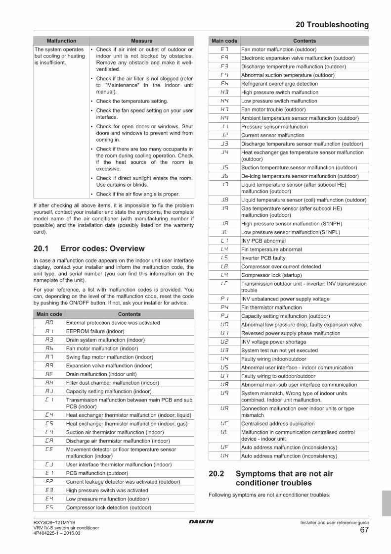
20 Troubleshooting
Installer and user reference guide
67RXYSQ8~12TMY1BVRV IV-S system air conditioner4P404225-1 – 2015.03
Malfunction MeasureThe system operatesbut cooling or heatingis insufficient.
▪ Check if air inlet or outlet of outdoor orindoor unit is not blocked by obstacles.Remove any obstacle and make it well-ventilated.
▪ Check if the air filter is not clogged (referto "Maintenance" in the indoor unitmanual).
▪ Check the temperature setting.
▪ Check the fan speed setting on your userinterface.
▪ Check for open doors or windows. Shutdoors and windows to prevent wind fromcoming in.
▪ Check if there are too many occupants inthe room during cooling operation. Checkif the heat source of the room isexcessive.
▪ Check if direct sunlight enters the room.Use curtains or blinds.
▪ Check if the air flow angle is proper.
If after checking all above items, it is impossible to fix the problemyourself, contact your installer and state the symptoms, the completemodel name of the air conditioner (with manufacturing number ifpossible) and the installation date (possibly listed on the warrantycard).
20.1 Error codes: OverviewIn case a malfunction code appears on the indoor unit user interfacedisplay, contact your installer and inform the malfunction code, theunit type, and serial number (you can find this information on thenameplate of the unit).
For your reference, a list with malfunction codes is provided. Youcan, depending on the level of the malfunction code, reset the codeby pushing the ON/OFF button. If not, ask your installer for advice.
Main code ContentsExternal protection device was activatedEEPROM failure (indoor)Drain system malfunction (indoor)Fan motor malfunction (indoor)Swing flap motor malfunction (indoor)Expansion valve malfunction (indoor)Drain malfunction (indoor unit)Filter dust chamber malfunction (indoor)Capacity setting malfunction (indoor)Transmission malfunction between main PCB and subPCB (indoor)Heat exchanger thermistor malfunction (indoor; liquid)Heat exchanger thermistor malfunction (indoor; gas)Suction air thermistor malfunction (indoor)Discharge air thermistor malfunction (indoor)Movement detector or floor temperature sensormalfunction (indoor)User interface thermistor malfunction (indoor)PCB malfunction (outdoor)Current leakage detector was activated (outdoor)High pressure switch was activatedLow pressure malfunction (outdoor)Compressor lock detection (outdoor)
Main code ContentsFan motor malfunction (outdoor)Electronic expansion valve malfunction (outdoor)Discharge temperature malfunction (outdoor)Abnormal suction temperature (outdoor)Refrigerant overcharge detectionHigh pressure switch malfunctionLow pressure switch malfunctionFan motor trouble (outdoor)Ambient temperature sensor malfunction (outdoor)Pressure sensor malfunctionCurrent sensor malfunctionDischarge temperature sensor malfunction (outdoor)Heat exchanger gas temperature sensor malfunction(outdoor)Suction temperature sensor malfunction (outdoor)De-icing temperature sensor malfunction (outdoor)Liquid temperature sensor (after subcool HE)malfunction (outdoor)Liquid temperature sensor (coil) malfunction (outdoor)Gas temperature sensor (after subcool HE)malfunction (outdoor)High pressure sensor malfunction (S1NPH)Low pressure sensor malfunction (S1NPL)INV PCB abnormalFin temperature abnormalInverter PCB faultyCompressor over current detectedCompressor lock (startup)Transmission outdoor unit - inverter: INV transmissiontroubleINV unbalanced power supply voltageFin thermistor malfunctionCapacity setting malfunction (outdoor)Abnormal low pressure drop, faulty expansion valveReversed power supply phase malfunctionINV voltage power shortageSystem test run not yet executedFaulty wiring indoor/outdoorAbnormal user interface - indoor communicationFaulty wiring to outdoor/outdoorAbnormal main-sub user interface communicationSystem mismatch. Wrong type of indoor unitscombined. Indoor unit malfunction.Connection malfunction over indoor units or typemismatchCentralised address duplicationMalfunction in communication centralised controldevice - indoor unitAuto address malfunction (inconsistency)Auto address malfunction (inconsistency)
20.2 Symptoms that are not airconditioner troubles
Following symptoms are not air conditioner troubles:
20 Troubleshooting
Installer and user reference guide
68RXYSQ8~12TMY1B
VRV IV-S system air conditioner4P404225-1 – 2015.03
20.2.1 Symptom: The system does not operate▪ The air conditioner does not start immediately after the ON/OFF
button on the user interface is pressed. If the operation lamplights, the system is in normal condition. To prevent overloading ofthe compressor motor, the air conditioner starts 5 minutes after itis turned ON again in case it was turned OFF just before. Thesame starting delay occurs after the operation mode selectorbutton was used.
▪ If "Under Centralized Control" is displayed on the user interface,pressing the operation button causes the display to blink for a fewseconds. The blinking display indicates that the user interfacecannot be used.
▪ The system does not start immediately after the power supply isturned on. Wait one minute until the micro computer is preparedfor operation.
20.2.2 Symptom: Fan operation is possible, butcooling and heating do not work
Immediately after the power is turned on. The micro computer isgetting ready to operate and is performing a communication checkwith all indoor units. Please wait 12 minutes (max.) till this process isfinished.
20.2.3 Symptom: The fan strength does notcorrespond to the setting
The fan speed does not change even if the fan speed adjustmentbutton in pressed. During heating operation, when the roomtemperature reaches the set temperature, the outdoor unit goes offand the indoor unit changes to whisper fan speed. This is to preventcold air blowing directly on occupants of the room. The fan speedwill not change even when another indoor unit is in heatingoperation, if the button is pressed.
20.2.4 Symptom: The fan direction does notcorrespond to the setting
The fan direction does not correspond with the user interfacedisplay. The fan direction does not swing. This is because the unit isbeing controlled by the micro computer.
20.2.5 Symptom: White mist comes out of a unit(Indoor unit)
▪ When humidity is high during cooling operation. If the interior of anindoor unit is extremely contaminated, the temperature distributioninside a room becomes uneven. It is necessary to clean theinterior of the indoor unit. Ask your dealer for details on cleaningthe unit. This operation requires a qualified service person.
▪ Immediately after the cooling operation stops and if the roomtemperature and humidity are low. This is because warmrefrigerant gas flows back into the indoor unit and generatessteam.
20.2.6 Symptom: White mist comes out of a unit(Indoor unit, outdoor unit)
When the system is changed over to heating operation after defrostoperation. Moisture generated by defrost becomes steam and isexhausted.
20.2.7 Symptom: The user interface displayreads "U4" or "U5" and stops, but thenrestarts after a few minutes
This is because the user interface is intercepting noise from electricappliances other than the air conditioner. The noise preventscommunication between the units, causing them to stop. Operationautomatically restarts when the noise ceases.
20.2.8 Symptom: Noise of air conditioners(Indoor unit)
▪ A "zeen" sound is heard immediately after the power supply isturned on. The electronic expansion valve inside an indoor unitstarts working and makes the noise. Its volume will reduce inabout one minute.
▪ A continuous low "shah" sound is heard when the system is incooling operation or at a stop. When the drain pump (optionalaccessories) is in operation, this noise is heard.
▪ A "pishi-pishi" squeaking sound is heard when the system stopsafter heating operation. Expansion and contraction of plastic partscaused by temperature change make this noise.
▪ A low "sah", "choro-choro" sound is heard while the indoor unit isstopped. When another indoor unit is in operation, this noise isheard. In order to prevent oil and refrigerant from remaining in thesystem, a small amount of refrigerant is kept flowing.
20.2.9 Symptom: Noise of air conditioners(Indoor unit, outdoor unit)
▪ A continuous low hissing sound is heard when the system is incooling or defrost operation. This is the sound of refrigerant gasflowing through both indoor and outdoor units.
▪ A hissing sound which is heard at the start or immediately afterstopping operation or defrost operation. This is the noise ofrefrigerant caused by flow stop or flow change.
20.2.10 Symptom: Noise of air conditioners(Outdoor unit)
When the tone of operating noise changes. This noise is caused bythe change of frequency.
20.2.11 Symptom: Dust comes out of the unitWhen the unit is used for the first time in a long time. This isbecause dust has gotten into the unit.
20.2.12 Symptom: The units can give off odoursThe unit can absorb the smell of rooms, furniture, cigarettes, etc.,and then emit it again.
20.2.13 Symptom: The outdoor unit fan does notspin
During operation. The speed of the fan is controlled in order tooptimise product operation.
20.2.14 Symptom: The display shows "88"This is the case immediately after the main power supply switch isturned on and means that the user interface is in normal condition.This continues for one minute.
21 Relocation
Installer and user reference guide
69RXYSQ8~12TMY1BVRV IV-S system air conditioner4P404225-1 – 2015.03
20.2.15 Symptom: The compressor in the outdoorunit does not stop after a short heatingoperation
This is to prevent refrigerant from remaining in the compressor. Theunit will stop after 5 to 10 minutes.
20.2.16 Symptom: The inside of an outdoor unit iswarm even when the unit has stopped
This is because the crankcase heater is warming the compressor sothat the compressor can start smoothly.
20.2.17 Symptom: Hot air can be felt when theindoor unit is stopped
Several different indoor units are being run on the same system.When another unit is running, some refrigerant will still flow throughthe unit.
21 RelocationContact your dealer for removing and reinstalling the total unit.Moving units requires technical expertise.
22 DisposalThis unit uses hydrofluorocarbon. Contact your dealer whendiscarding this unit. It is required by law to collect, transport anddiscard the refrigerant in accordance with the "hydrofluorocarboncollection and destruction" regulations.
23 GlossaryDealer
Sales distributor for the product.
Authorized installerTechnical skilled person who is qualified to install theproduct.
UserPerson who is owner of the product and/or operates theproduct.
Applicable legislationAll international, European, national and local directives,laws, regulations and/or codes that are relevant andapplicable for a certain product or domain.
Service companyQualified company which can perform or coordinate therequired service to the product.
Installation manualInstruction manual specified for a certain product orapplication, explaining how to install, configure and maintainit.
Operation manualInstruction manual specified for a certain product orapplication, explaining how to operate it.
AccessoriesLabels, manuals, information sheets and equipment that aredelivered with the product and that need to be installedaccording to the instructions in the accompanyingdocumentation.
Optional equipmentEquipment made or approved by Daikin that can becombined with the product according to the instructions inthe accompanying documentation.
Field supplyEquipment not made by Daikin that can be combined withthe product according to the instructions in theaccompanying documentation.


4P404225-1 2015.03
Cop
yrig
ht 2
015
Dai
kin


