Installing Strain Gain Transducers 1 INTRODUCTION Installing a HELM load monitor or a load measurement system can be divided into four basic segments: 1.) Selecting the sensor mounting locations. 2.) Installing the STRAlN GAIN load sensors and instrument. 3.) Inter-connecting the sensors to the instrument. 4.) Calibrating the press and making final instrument-adjustments. Generally, HELM is requested to supervise the customer’s personnel for steps 1,2 and 3. We almost always do the calibration. Special equipment and training is required for the calibration and adjustment (step #4). This article is provided for those customers who are confident they can perform the first three steps without our direct supervision. Part of this article explains the role of the customer in the final calibration procedure. SELECTING THE SENSOR LOCATION Basic Principles of Measuring Press Loads As a press forms a product, the press structure is strained. The tie-rods and columns of a straightside press will stretch. The frame of a Gap-Frame or O.B.I. press will open up. The amount of strain on the press is directly related to the work that is done... the ”load” on the press structure. Strain-sensing ”transducers” are mounted to strategic high-stress areas of the press frame. Sig- nals from these sensors are routed to the instrument for processing. The instrument will display the strain in ”tons-of-force” or in ”percentage-of press capacity”. Adjustable alarm levels are provided in the instrument so the customer may select what he considers an off-tolerance or overload condition. Some areas of the press structure are highly stressed and provide excellent representative load- signals. Other areas are lightly stressed and only poor and non-linear signals are available. Only a few years ago, picking a good sensor location was only done by specially trained people. HELM development has produced highly sophisticated sensitive instruments with extreme stability. Sensor locations that were useless only a few years ago are now perfectly satisfactory for use with our systems. With our modern systems, and using reasonable care, it is now practical for a customer to pick sensor locations on common presses. True, such machines as under-drives, multi-column presses and special ”exotic” presses still need professional study. In special cases, simply con- tact us and we will tell you the best location for your sensor.
Transcript
Installing Strain Gain Transducers
1
INTRODUCTION
Installing a HELM load monitor or a load measurement system can be divided into four basicsegments:
1.) Selecting the sensor mounting locations.2.) Installing the STRAlN GAIN load sensors and instrument.3.) Inter-connecting the sensors to the instrument.4.) Calibrating the press and making final instrument-adjustments.
Generally, HELM is requested to supervise the customer’s personnel for steps 1,2 and 3. Wealmost always do the calibration. Special equipment and training is required for the calibration andadjustment (step #4). This article is provided for those customers who are confident they canperform the first three steps without our direct supervision. Part of this article explains the role ofthe customer in the final calibration procedure.
SELECTING THE SENSOR LOCATION
Basic Principles of Measuring Press Loads
As a press forms a product, the press structure is strained. The tie-rods and columns of astraightside press will stretch. The frame of a Gap-Frame or O.B.I. press will open up. Theamount of strain on the press is directly related to the work that is done... the ”load” on the pressstructure.
Strain-sensing ”transducers” are mounted to strategic high-stress areas of the press frame. Sig-nals from these sensors are routed to the instrument for processing. The instrument will displaythe strain in ”tons-of-force” or in ”percentage-of press capacity”. Adjustable alarm levels areprovided in the instrument so the customer may select what he considers an off-tolerance oroverload condition.
Some areas of the press structure are highly stressed and provide excellent representative load-signals. Other areas are lightly stressed and only poor and non-linear signals are available. Only afew years ago, picking a good sensor location was only done by specially trained people. HELMdevelopment has produced highly sophisticated sensitive instruments with extreme stability.Sensor locations that were useless only a few years ago are now perfectly satisfactory for use withour systems.
With our modern systems, and using reasonable care, it is now practical for a customer to picksensor locations on common presses. True, such machines as under-drives, multi-columnpresses and special ”exotic” presses still need professional study. In special cases, simply con-tact us and we will tell you the best location for your sensor.
Installing Strain Gain Transducers
2
Selecting a Sensor Location... ”C” Frame Presses
A Gap-Frame or O.B.I. press ”opens” up when it does work. This puts the throat area in tensionand the rear of the web of the press in compression. Figures 1 & 9 show typical sensor- mountinglocations on an O.B.I. press. Locations would be similar for a typical Gap-Frame press. Pick alocation where the sensor will not be damaged by stock movement through the press, passingvehicles, changing tooling, etc.
We have found the load signals from the throat of the press to be the most dependable. The onlytime the rear of the press would be most desirable is when the throat area is obstructed withtooling. If the press has reinforcing tie-rods, the rear of the press cannot be used.
The best location wouId be in the throat area marked in gray. The manufacturer has generally”beefed up” this area because of the high stresses. Avoid putting the sensor near a corner or achange-in-section. That area could provide a non-linear signal. If at all possibIe, stay in the centerof the ”O.K.” zone (of figure 1). This area provides a good, dependable ”TENSION” sig- nal.
The second best location would be as near as possible to the rear edge of the upright web. Sometypes of presses have relatively thin webs. This causes them to bow in or out when the press isloaded. The load signal will be distorted if such bowing is significant or excessive. Sensors at therear of the press will provide a usable ”COMPRESSION” signal.
The area marked ”no good” must be avoided. Also, avoid putting sensors near the gibs. Signalsnear the gib area may vary from somewhat non-linear to extremely weak. Try to mount thesensors at the same height on the press. For example; if you put the left sensor at the left edge ofthe throat, 4 inches above the bed, mount the right sensor on the right edge of the throat, 4 inchesabove the bed.
NO GOOD
GOOD GOOD GOOD GOOD
- Fig. 1 -
Installing Strain Gain Transducers
3
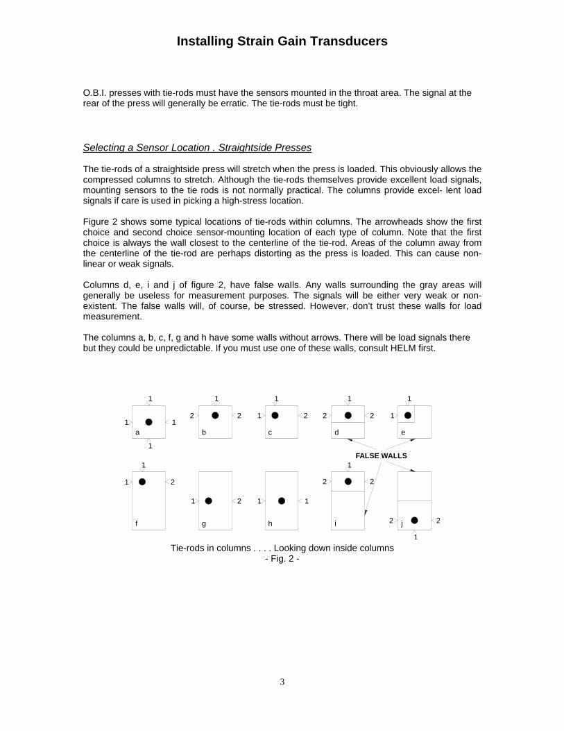
O.B.I. presses with tie-rods must have the sensors mounted in the throat area. The signal at therear of the press will generaIly be erratic. The tie-rods must be tight.
Selecting a Sensor Location . Straightside Presses
The tie-rods of a straightside press will stretch when the press is loaded. This obviously allows thecompressed columns to stretch. Although the tie-rods themselves provide excellent load signals,mounting sensors to the tie rods is not normally practical. The columns provide excel- lent loadsignals if care is used in picking a high-stress location.
Figure 2 shows some typical locations of tie-rods within columns. The arrowheads show the firstchoice and second choice sensor-mounting location of each type of column. Note that the firstchoice is always the wall closest to the centerline of the tie-rod. Areas of the column away fromthe centerline of the tie-rod are perhaps distorting as the press is loaded. This can cause non-linear or weak signals.
Columns d, e, i and j of figure 2, have false waIls. Any walls surrounding the gray areas willgenerally be useless for measurement purposes. The signals will be either very weak or non-existent. The false walls will, of course, be stressed. However, don’t trust these walls for loadmeasurement.
The columns a, b, c, f, g and h have some walls without arrows. There will be load signals therebut they could be unpredictable. If you must use one of these walls, consult HELM first.
f
1
1
1
1
a
1
g
2
1 2
h i
1
2
1
2 j
1
FALSE WALLS
2
1
2
12
b
1
2
c
1
1
d
2 2
1
2
e
1
1
Tie-rods in columns . . . . Looking down inside columns- Fig. 2 -
Installing Strain Gain Transducers
4
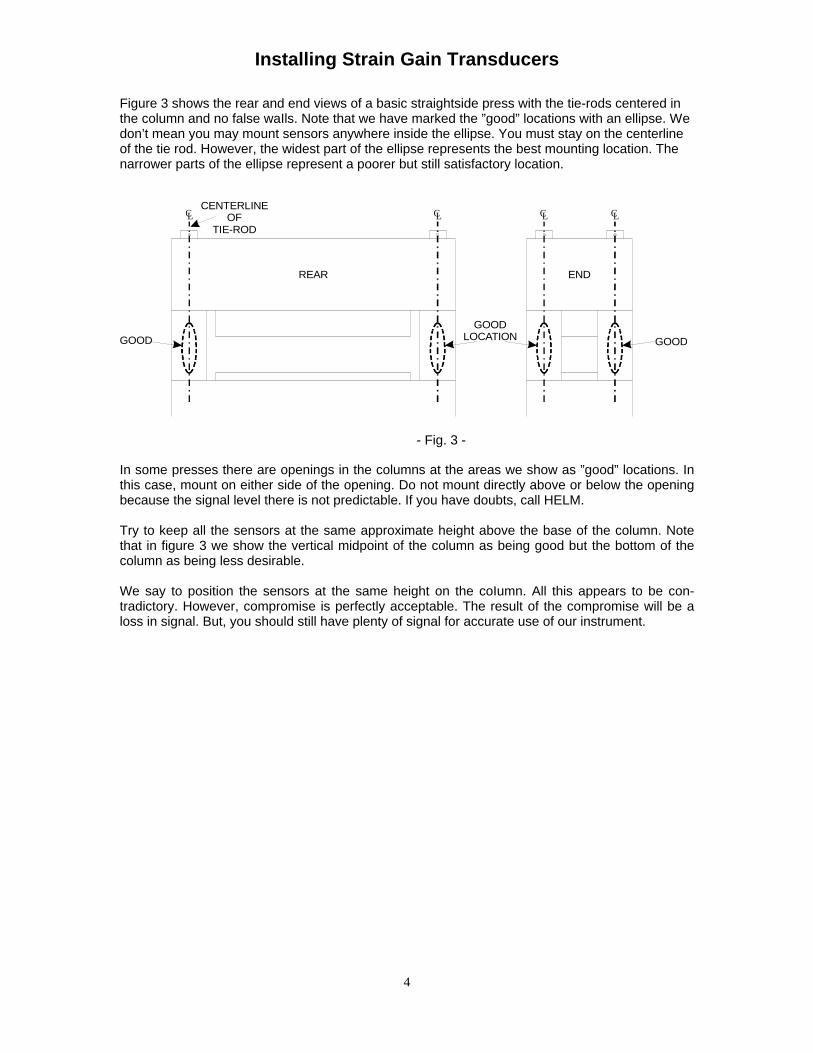
Figure 3 shows the rear and end views of a basic straightside press with the tie-rods centered inthe column and no false waIls. Note that we have marked the ”good” locations with an ellipse. Wedon’t mean you may mount sensors anywhere inside the ellipse. You must stay on the centerlineof the tie rod. However, the widest part of the ellipse represents the best mounting location. Thenarrower parts of the ellipse represent a poorer but still satisfactory location.
CLCLCLCL
GOOD
REAR
GOODLOCATION
END
GOOD
CENTERLINEOF
TIE-ROD
In some presses there are openings in the columns at the areas we show as ”good” locations. Inthis case, mount on either side of the opening. Do not mount directly above or below the openingbecause the signal level there is not predictable. If you have doubts, call HELM.
Try to keep all the sensors at the same approximate height above the base of the column. Notethat in figure 3 we show the vertical midpoint of the column as being good but the bottom of thecolumn as being less desirable.
We say to position the sensors at the same height on the coIumn. All this appears to be con-tradictory. However, compromise is perfectly acceptable. The result of the compromise will be aloss in signal. But, you should still have plenty of signal for accurate use of our instrument.
- Fig. 3 -
Installing Strain Gain Transducers
5
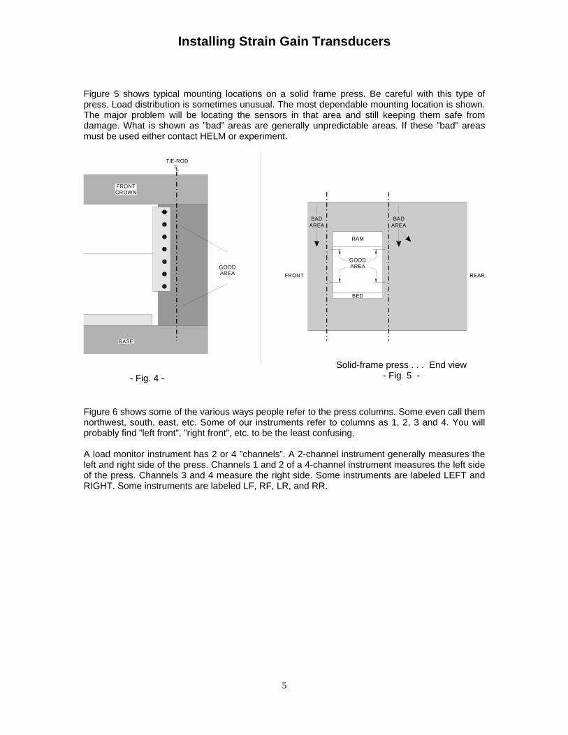
Figure 5 shows typical mounting locations on a solid frame press. Be careful with this type ofpress. Load distribution is sometimes unusual. The most dependable mounting location is shown.The major problem will be locating the sensors in that area and still keeping them safe fromdamage. What is shown as ”bad” areas are generally unpredictable areas. If these ”bad” areasmust be used either contact HELM or experiment.
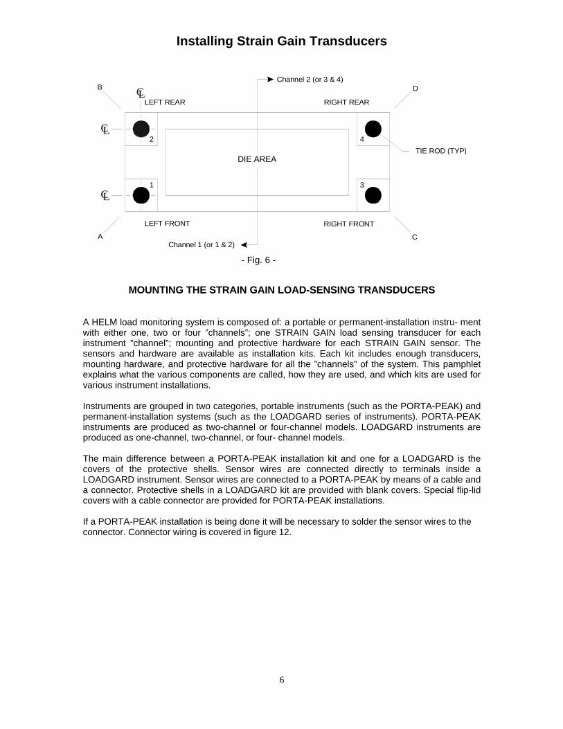
Figure 6 shows some of the various ways people refer to the press columns. Some even call themnorthwest, south, east, etc. Some of our instruments refer to columns as 1, 2, 3 and 4. You willprobably find ”left front”, ”right front”, etc. to be the least confusing.
A load monitor instrument has 2 or 4 ”channels”. A 2-channel instrument generally measures theleft and right side of the press. Channels 1 and 2 of a 4-channel instrument measures the left sideof the press. Channels 3 and 4 measure the right side. Some instruments are labeled LEFT andRIGHT. Some instruments are labeled LF, RF, LR, and RR.
- Fig. 4 -
Solid-frame press . . . End view- Fig. 5 -
AREA
BED
FRONT
AREABAD
GOODAREA
RAM
BAD
REAR
LCTIE-ROD
BASE
FRONTCROWN
GOODAREA
Installing Strain Gain Transducers
6
LC
LC
LC
DIE AREA
2
AChannel 1 (or 1 & 2)
LEFT FRONT
1
B
LEFT REAR
4
RIGHT FRONT
3
C
TIE ROD (TYP)
RIGHT REAR
Channel 2 (or 3 & 4)D
MOUNTING THE STRAIN GAIN LOAD-SENSING TRANSDUCERS
A HELM load monitoring system is composed of: a portable or permanent-installation instru- mentwith either one, two or four ”channels”; one STRAIN GAIN load sensing transducer for eachinstrument ”channel”; mounting and protective hardware for each STRAIN GAIN sensor. Thesensors and hardware are available as installation kits. Each kit includes enough transducers,mounting hardware, and protective hardware for all the ”channels” of the system. This pamphletexplains what the various components are called, how they are used, and which kits are used forvarious instrument installations.
Instruments are grouped in two categories, portable instruments (such as the PORTA-PEAK) andpermanent-installation systems (such as the LOADGARD series of instruments). PORTA-PEAKinstruments are produced as two-channel or four-channel models. LOADGARD instruments areproduced as one-channel, two-channel, or four- channel models.
The main difference between a PORTA-PEAK installation kit and one for a LOADGARD is thecovers of the protective shells. Sensor wires are connected directly to terminals inside aLOADGARD instrument. Sensor wires are connected to a PORTA-PEAK by means of a cable anda connector. Protective shells in a LOADGARD kit are provided with blank covers. Special flip-lidcovers with a cable connector are provided for PORTA-PEAK installations.
If a PORTA-PEAK installation is being done it will be necessary to solder the sensor wires to theconnector. Connector wiring is covered in figure 12.
- Fig. 6 -
Installing Strain Gain Transducers
7
TWO TYPES OF MOUNTING KITS... WELD OR DRILL
There are two methods of mounting the load sensors to a machine... Direct mounting by means ofholes drilled into the machine... Indirect mounting by using pre-drilled steel blocks (weld pads)welded to the machine. Therefore, kits will be referred to as either ”Weld-Pad” mounting or”Drilled-Hole” mounting.
There are a total of ten transducer/installation kits. Four kits are for the PORTA-PEAK instru-ments. Six kits are for permanent-installation systems such as LOADGARD. Here is how they aredivided:
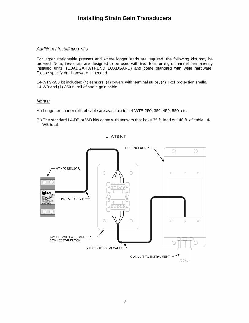
For larger straightside presses and where longer leads are required, the following kits may beordered. Note, these kits are designed to be used with two, four, or eight channel permanentlyinstalled units, (LOADGARD/TREND LOADGARD) and come standard with weld hardware.Please specify drill hardware, if needed.
L4-WTS-350 kit includes: (4) sensors, (4) covers with terminal strips, (4) T-21 protection shells.L4-WB and (1) 350 ft. roll of strain gain cable.
Notes:
A.) Longer or shorter rolls of cable are available ie: L4-WTS-250, 350, 450, 550, etc.
B.) The standard L4-DB or WB kits come with sensors that have 35 ft. lead or 140 ft. of cable L4- WB total.
Installing Strain Gain Transducers
9
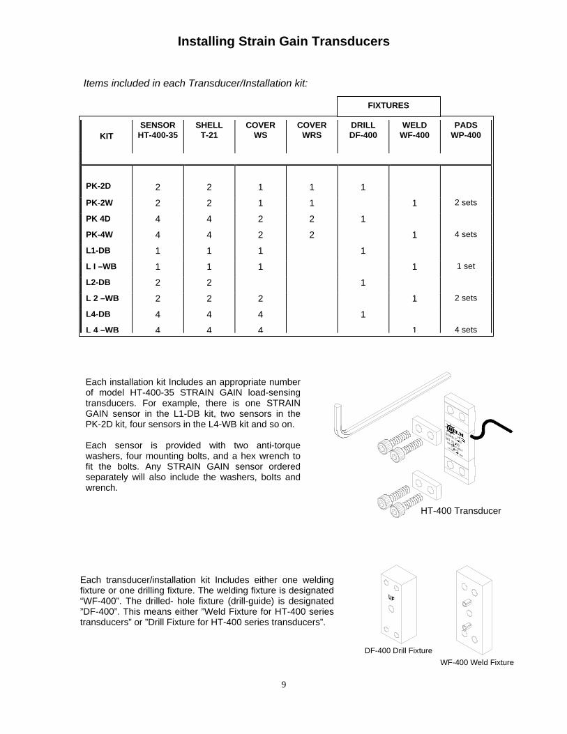
Items included in each Transducer/Installation kit:
KITSENSOR
HT-400-35SHELL
T-21COVER
WSCOVER
WRSDRILLDF-400
WELDWF-400
PADSWP-400
PK-2D 2 2 1 1 1
PK-2W 2 2 1 1 1 2 sets
PK 4D 4 4 2 2 1
PK-4W 4 4 2 2 1 4 sets
L1-DB 1 1 1 1
L I –WB 1 1 1 1 1 set
L2-DB 2 2 1
L 2 –WB 2 2 2 1 2 sets
L4-DB 4 4 4 1
L 4 –WB 4 4 4 1 4 sets
Each installation kit Includes an appropriate numberof model HT-400-35 STRAIN GAIN load-sensingtransducers. For example, there is one STRAINGAIN sensor in the L1-DB kit, two sensors in thePK-2D kit, four sensors in the L4-WB kit and so on.
Each sensor is provided with two anti-torquewashers, four mounting bolts, and a hex wrench tofit the bolts. Any STRAIN GAIN sensor orderedseparately will also include the washers, boIts andwrench.
Each transducer/installation kit Includes either one weldingfixture or one drilling fixture. The welding fixture is designated“WF-400”. The drilled- hole fixture (drill-guide) is designated”DF-400”. This means either ”Weld Fixture for HT-400 seriestransducers” or ”Drill Fixture for HT-400 series transducers”.
FIXTURES
DF-400 Drill Fixture
WF-400 Weld Fixture
HT-400 Transducer
Installing Strain Gain Transducers
10
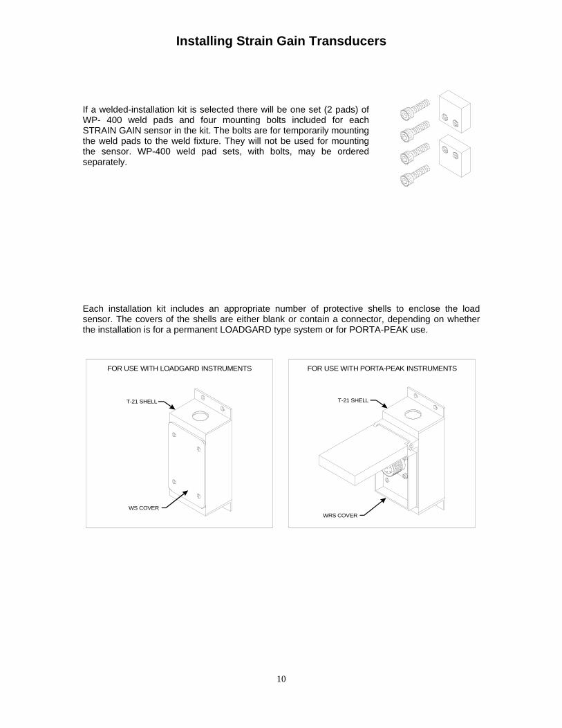
If a welded-installation kit is selected there will be one set (2 pads) ofWP- 400 weld pads and four mounting bolts included for eachSTRAIN GAIN sensor in the kit. The bolts are for temporarily mountingthe weld pads to the weld fixture. They will not be used for mountingthe sensor. WP-400 weld pad sets, with bolts, may be orderedseparately.
Each installation kit includes an appropriate number of protective shells to enclose the loadsensor. The covers of the shells are either blank or contain a connector, depending on whetherthe installation is for a permanent LOADGARD type system or for PORTA-PEAK use.
WRS COVER
T-21 SHELL
WS COVER
T-21 SHELL
FOR USE WITH PORTA-PEAK INSTRUMENTSFOR USE WITH LOADGARD INSTRUMENTS
Installing Strain Gain Transducers
11
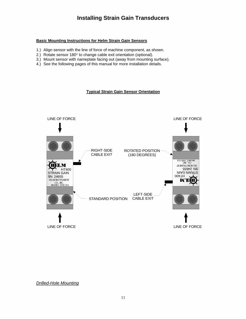
Basic Mounting Instructions for Helm Strain Gain Sensors
1.) Align sensor with the line of force of machine component, as shown.2.) Rotate sensor 180° to change cable exit orientation (optional).3.) Mount sensor with nameplate facing out (away from mounting surface).4.) See the following pages of this manual for more installation details.
Typical Strain Gain Sensor Orientation
MAUMEE, OHIO USA
S/NHELM INSTRUMENT
CO., INC.
STRAIN GAIN24655
HT400
MAUMEE, OHIO USA
S/NHELM INSTRUMENT
CO., INC.
STRAIN GAIN24655
HT400
LINE OF FORCE
LINE OF FORCE
STANDARD POSITION
RIGHT-SIDECABLE EXIT
LEFT-SIDECABLE EXIT
ROTATED POSITION(180 DEGREES)
LINE OF FORCE
LINE OF FORCE
Drilled-Hole Mounting
Installing Strain Gain Transducers
12
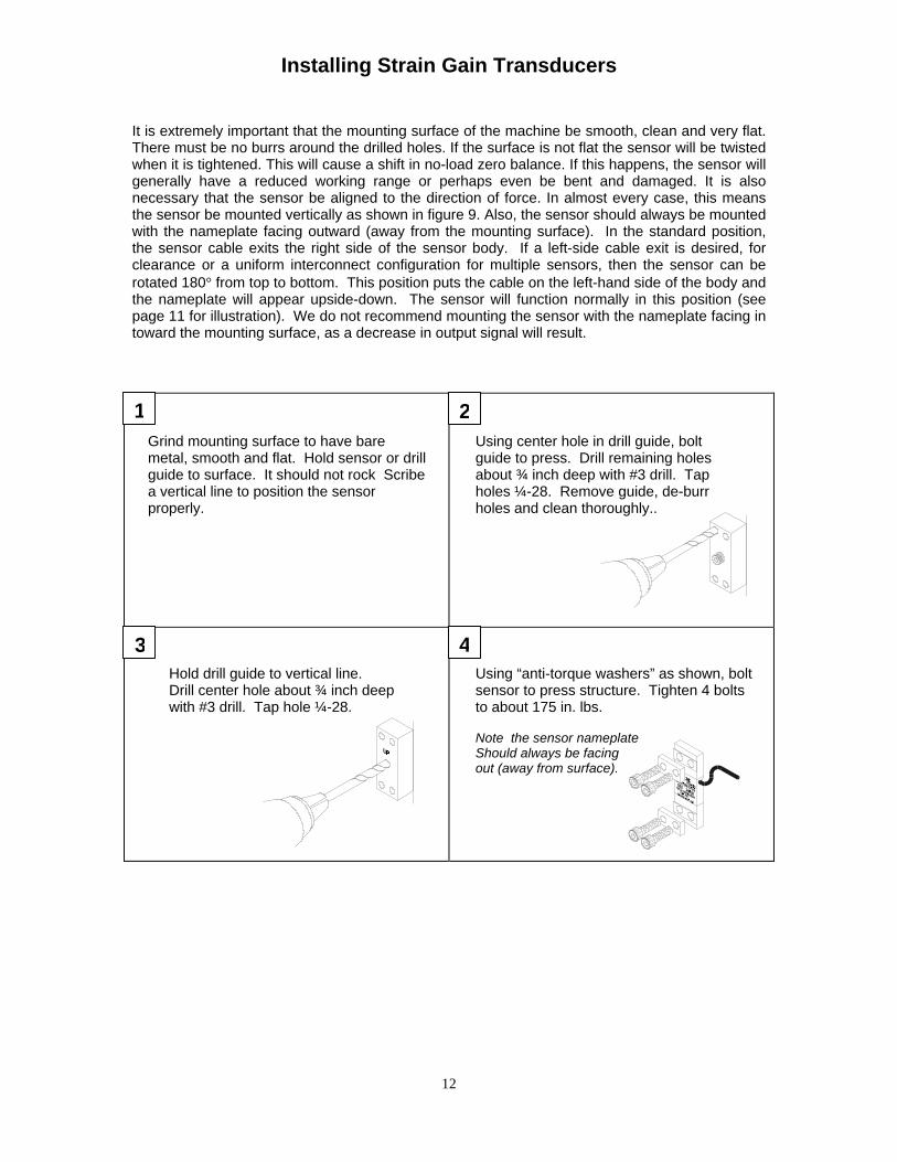
It is extremely important that the mounting surface of the machine be smooth, clean and very flat.There must be no burrs around the drilled holes. If the surface is not flat the sensor will be twistedwhen it is tightened. This will cause a shift in no-load zero balance. If this happens, the sensor willgenerally have a reduced working range or perhaps even be bent and damaged. It is alsonecessary that the sensor be aligned to the direction of force. In almost every case, this meansthe sensor be mounted vertically as shown in figure 9. Also, the sensor should always be mountedwith the nameplate facing outward (away from the mounting surface). In the standard position,the sensor cable exits the right side of the sensor body. If a left-side cable exit is desired, forclearance or a uniform interconnect configuration for multiple sensors, then the sensor can berotated 180° from top to bottom. This position puts the cable on the left-hand side of the body andthe nameplate will appear upside-down. The sensor will function normally in this position (seepage 11 for illustration). We do not recommend mounting the sensor with the nameplate facing intoward the mounting surface, as a decrease in output signal will result.
1 2
3 4
Grind mounting surface to have baremetal, smooth and flat. Hold sensor or drillguide to surface. It should not rock Scribea vertical line to position the sensorproperly.
Using center hole in drill guide, boltguide to press. Drill remaining holesabout ¾ inch deep with #3 drill. Tapholes ¼-28. Remove guide, de-burrholes and clean thoroughly..
Hold drill guide to vertical line.Drill center hole about ¾ inch deepwith #3 drill. Tap hole ¼-28.
Using “anti-torque washers” as shown, boltsensor to press structure. Tighten 4 boltsto about 175 in. lbs.
Note the sensor nameplateShould always be facingout (away from surface).
Installing Strain Gain Transducers
13
NOTE: If you have protective shells (T-21) for enclosing the sensor, see figure 10 and the ac-companying text for special procedures.
Weld-Pad Mounting
There are some simpIe cautions to observe when using the weld-pad method of sensor mount-ing.
§§ You must assure the fixture and pads are properly aligned with the direction of force. This willalmost always be vertically as shown in figure 8 and figure 9.
§§ The pads must be held firmly against the machine surface and each pad must be tack-weldedbefore finish-weld is done. If only one pad is tack-welded, the other pad will generally lift awayfrom the surface. Unless both pads are firmly welded flat against the machine sur- face, thesensors may not provide proper load-sensing
§§ The finished weld shouId be tested by prying firmly with a screwdriver/between the fixture andmachine surface. A poor weld will obviously let go.
§§ The weId-pads must remain firmly attached to the fixture until all welding is complete and thefixture is cool enough to be held in a bare hand.
The weld-pads are made of 1018 mild steel. For welding to a cast iron machine we suggest N1-ROD-55 (INTERNATIONAL NICKEL CO.). Although a mounting hole is provided in the center ofthe fixture, most welders prefer to mereIy hold the fixture/pads firmly to the press with a glovedhand. In almost every case this works well.
NOTE: If you have protective shells (T-21) for enclosing the sensor, see figure 10 and the ac-companying text for special procedures.
Installing Strain Gain Transducers
14
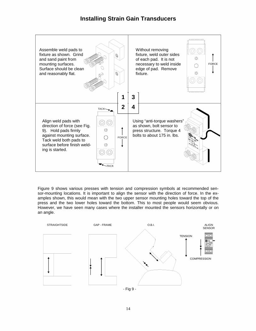
Figure 9 shows various presses with tension and compression symbols at recommended sen-sor-mounting locations. It is important to align the sensor with the direction of force. In the ex-amples shown, this would mean with the two upper sensor mounting holes toward the top of thepress and the two lower holes toward the bottom. This to most people would seem obvious.However, we have seen many cases where the instalIer mounted the sensors horizontally or onan angle.
HT400
24655S/NSTRAIN GAIN
HELM INSTRUMENTCO., INC.
MAUMEE, OHIO USA
GAP - FRAME
TENSION
ALIGNSENSOR
STRAIGHTSIDE
COMPRESSION
O.B.I.
- Fig 9 -
1 3
2 4TACK
TACK
FORCE
FORCE
Assemble weld pads tofixture as shown. Grindand sand paint frommounting surfaces.Surface should be cleanand reasonably flat.
Without removingfixture, weld outer sidesof each pad. It is notnecessary to weld insideedge of pad. Removefixture.
Align weld pads withdirection of force (see Fig.9). Hold pads firmlyagainst mounting surface.Tack weld both pads tosurface before finish weld-ing is started.
Using “anti-torque washers”as shown, bolt sensor topress structure. Torque 4bolts to about 175 in. lbs.
Installing Strain Gain Transducers
15
Mounting the Protective Shells (T-21)
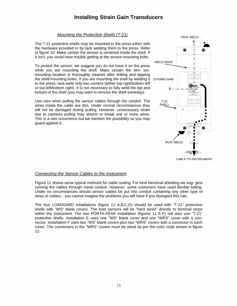
The T-21 protective shells may be mounted to the press either withthe hardware provided or by tack welding them to the press. Referto figure 10. Make certain the sensor is centered inside the shell. Ifit isn’t, you couId have trouble getting at the sensor-mounting bolts.
To protect the sensor, we suggest you do not have it on the presswhile you are mounting the shell. Make certain the sen- sor-mounting location is thoroughly cleaned after drilling and tappingthe shell-mounting holes. If you are mounting the shell by welding itto the press, tack-weld only two corners (either top-right/bottom leftor top-left/bottom right). It is not necessary to fully weld the top andbottom of the shell (you may want to remove the shell someday).
Use care when pulling the sensor cables through the conduit. Thewires inside the cable are thin. Under normal circumstances theywill not be damaged during pulling. However, unnecessary straindue to careless pulling may stretch or break one or more wires.This is a rare occurrence but we mention the possibility so you mayguard against it.
Connecting the Sensor Cables to the Instrument
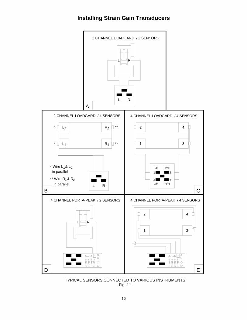
Figure 11 shows some typical methods for cable routing. For best electrical shielding we sug- gestrunning the cables through metal conduit. However, some customers have used flexible tubing.Under no circumstances should sensor cables be put into conduit containing any other type ofwires or cables... you cannot imagine the problems you will have if you disregard this rule.
The four LOADGARD installations (figure 11 A,B,C,D) should be used with ”T-21” protectiveshells with ”WS” blank covers. The load sensors will be ”hard wired” directly to terminal stripswithin the instrument. The two PORTA-PEAK installation (figures 11 E,F) will aIso use ”T-21”protective shells. Installation E uses one ”WS” blank cover and one ”WRS” cover with a con-nector. InstaIlation F uses two ”WS” blank covers plus two ”WRS” covers with a connector in eachcover. The connectors in the ”WRS” covers must be wired as per the color code shown in figure12.
CL
CL
TACK WELD
CABLE TO INSTRUMENT
WELD PADS
STRAIN GAIN
T-21SHELL
TACK WELD
24655STRAIN GAIN
CO., INC.MAUMEE, OHIO USA
HELM INSTRUMENTS/N
HT400
- Fig. 10 -
Installing Strain Gain Transducers
16
2 CHANNEL LOADGARD / 2 SENSORS
L R
R
2 CHANNEL LOADGARD / 4 SENSORS
4 CHANNEL PORTA-PEAK / 2 SENSORS
L*
A
2* L
** Wire R & R
* Wire L & L
B
1
in parallel1 2
in parallel1 2
L
**R
4 CHANNEL LOADGARD / 4 SENSORS
RL
**2R
4 CHANNEL PORTA-PEAK / 4 SENSORS
L/F
L/R
1
1
2
R/F
3
R/R4
C
D
L R
1
2
3
4
E
TYPICAL SENSORS CONNECTED TO VARIOUS INSTRUMENTS- Fig. 11 -
Installing Strain Gain Transducers
17
Please note that the wiring diagram shows the rear of the connector, #1 sensor is on the right.Soldering small wires into a connector requires care and skill. Make certain there are no shorts or
solder bridging between the terminals. It is good practice to place short pieces of plastic tubing(spaghetti) over the terminals. The wiring diagram shows the connections for sensors with a
TENSION signal (see figure 9). For a COMPRESSION signal you should put both green wires toterminaI B and both black wires to terminal A. This will reverse the excitation to the strain gagesinside the sensor. DO NOT change the white and red wires PLUS the red and black wires. To do
so would put you right back where you started.
It is perfectly acceptable to coil up some excess sensor cable within the protective shell. Just don’ttry to stuff the shell full. It is also perfectly acceptable to cut off unneeded excess cable. This willnot affect the accuracy of the load measurements. It is not acceptable to splice the cable withoutinstructions from HELM.
Proper terminations to LOADGARD type instruments will be covered fully in each instructionmanual.
7 PIN FEMALE AMPHENOL CONNECTOR
BACK VIEW
E
A
D C
G
F
B
7 PIN FEMALE AMPHENOLCONNECTOR
PIN A - (+GAGE)
PIN D - (-SIGNAL)
PIN F - (OPEN)PIN G - (SHIELD)
PIN E - (OPEN)
PIN C - (+SIGNAL)PIN B - (-GAGE)
WRS COVER
CONNECTOR CODE
T-21 ENCLOSURE
CALIBRATING THE PRESS AND INSTRUMENT
Complete details of press caIibration is beyond the scope of this article. Each instrument manualcontains details for making the instrument adjustments. What we present here is a basic descrip-tion of the calibration procedure and how the customer is involved in that calibration.
- Fig. 12 -
Installing Strain Gain Transducers
18
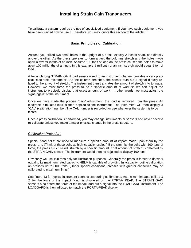
To calibrate a system requires the use of specialized equipment. If you have such equipment, youhave been trained how to use it. Therefore, you may ignore this section of the article.
Basic Principles of Calibration
Assume you drilled two small holes in the upright of a press, exactly 2 inches apart, one directlyabove the other. As the press operates to form a part, the columns stretch and the holes moveapart a few millionths of an inch. Assume 100 tons of load on the press caused the holes to moveapart 100 millionths of an inch. In this exampIe 1 millionth of an inch stretch would equal 1 ton ofload.
A two-inch long STRAIN GAlN load sensor wired to an instrument channel provides a very prac-tical ”electronic micrometer”. As the column stretches, the sensor puts out a signal directly re-lated to the amount of stretch. The instrument then translates the amount of stretch into tonnage.However, we must force the press to do a specific amount of work so we can adjust theinstrument to precisely display that exact amount of work. In other words, we must adjust thesignal ”gain” of the instrument.
Once we have made the precise “gain” adjustment, the load is removed from the press. Anelectronic simulated-load is then applied to the instrument. The instrument will then display a”CAL” (calibration) number. The CAL number is recorded for use whenever the system is to betested.
Once a press calibration is performed, you may change instruments or sensors and never need tore-calibrate unless you make a major physical change in the press structure.
Calibration Procedure
Special ”load cells” are used to measure a specific amount of impact made upon them by thepress ram. (Think of these cells as high-capacity scales.) If the ram hits the cells with 100 tons offorce, the press structure will stretch by a specific amount. That amount of stretch is detected bythe STRAIN GAIN sensor. The instrument would then be adjusted to display 100 tons.
Obviously we use 100 tons only for illustration purposes. Generally the press is forced to do workequal to its maximum rated capacity. HELM is capable of providing full-capacity routine calibrationon presses up to 8000 tons. (Under special conditions, presses with greater capacities may becalibrated to maximum limits.)
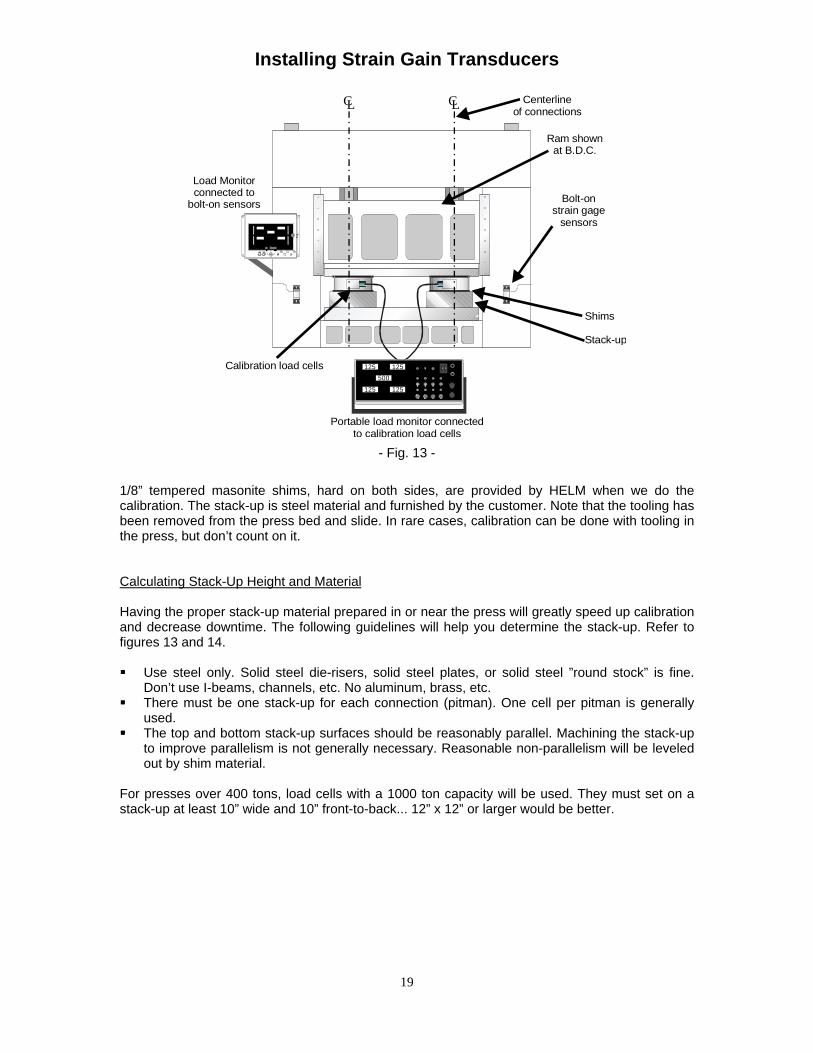
See figure 13 for typical instrument connections during caIibrations. As the ram impacts cells 1 &2, for the force of the impact (load) is displayed on the PORTA- PEAK. The STRAIN GAINsensors aIso detect the force of the impact and put a signal into the LOADGARD instrument. TheLOADGARD is then adjusted to match the PORTA-PEAK display.
1/8” tempered masonite shims, hard on both sides, are provided by HELM when we do thecalibration. The stack-up is steel material and furnished by the customer. Note that the tooling hasbeen removed from the press bed and slide. In rare cases, calibration can be done with tooling inthe press, but don’t count on it.
Calculating Stack-Up Height and Material
Having the proper stack-up material prepared in or near the press will greatly speed up calibrationand decrease downtime. The following guidelines will help you determine the stack-up. Refer tofigures 13 and 14.
§§ Use steel only. Solid steel die-risers, solid steel plates, or solid steel ”round stock” is fine.Don’t use I-beams, channels, etc. No aluminum, brass, etc.
§§ There must be one stack-up for each connection (pitman). One cell per pitman is generallyused.
§§ The top and bottom stack-up surfaces should be reasonably parallel. Machining the stack-upto improve parallelism is not generally necessary. Reasonable non-parallelism will be leveledout by shim material.
For presses over 400 tons, load cells with a 1000 ton capacity will be used. They must set on astack-up at least 10” wide and 10” front-to-back... 12” x 12” or larger would be better.
- Fig. 13 -
Installing Strain Gain Transducers
20
B=4 ¼ inches
A
C=A-B
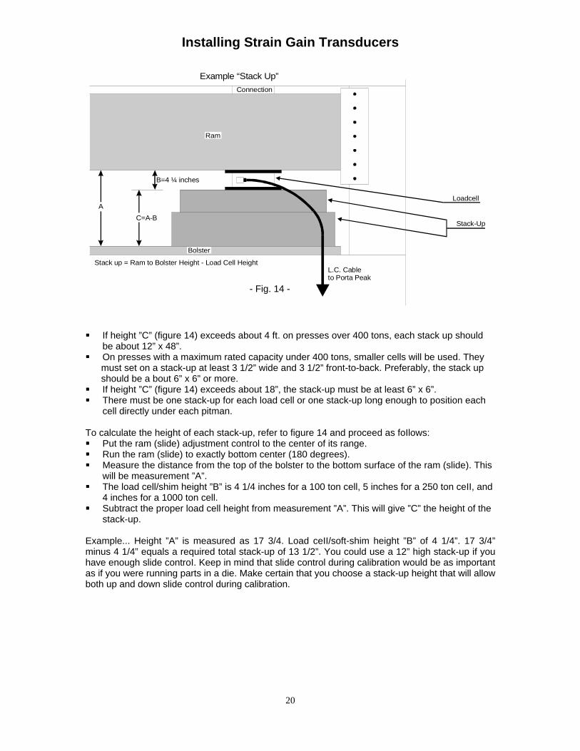
Stack up = Ram to Bolster Height - Load Cell Height
Bolster
Connection
Ram
Example “Stack Up”
Loadcell
Stack-Up
L.C. Cableto Porta Peak
§§ If height ”C” (figure 14) exceeds about 4 ft. on presses over 400 tons, each stack up shouldbe about 12” x 48”.
§§ On presses with a maximum rated capacity under 400 tons, smaller cells will be used. They must set on a stack-up at least 3 1/2” wide and 3 1/2” front-to-back. Preferably, the stack up should be a bout 6” x 6” or more.§§ If height ”C” (figure 14) exceeds about 18”, the stack-up must be at least 6” x 6”.§§ There must be one stack-up for each load cell or one stack-up long enough to position each
cell directly under each pitman.
To calculate the height of each stack-up, refer to figure 14 and proceed as foIlows:§§ Put the ram (slide) adjustment control to the center of its range.§§ Run the ram (slide) to exactly bottom center (180 degrees).§§ Measure the distance from the top of the bolster to the bottom surface of the ram (slide). This
will be measurement ”A”.§§ The load cell/shim height ”B” is 4 1/4 inches for a 100 ton cell, 5 inches for a 250 ton ceII, and
4 inches for a 1000 ton cell.§§ Subtract the proper load cell height from measurement ”A”. This will give ”C” the height of the
stack-up.
Example... Height ”A” is measured as 17 3/4. Load ceII/soft-shim height ”B” of 4 1/4”. 17 3/4”minus 4 1/4” equals a required total stack-up of 13 1/2”. You could use a 12” high stack-up if youhave enough slide controI. Keep in mind that slide control during calibration would be as importantas if you were running parts in a die. Make certain that you choose a stack-up height that will allowboth up and down slide control during calibration.