CHAPTER 3-1 Cisco 12404 Internet Router Installation and Configuration Guide OL-11636-01 3 Installing the Cisco 12404 Internet Router This chapter describes how to do the initial installation and setup of a Cisco 12404 Internet router. It includes: • Installing a Cisco 12404 Internet Router, page 3-2 • Connecting RP and Line Card Cables, page 3-11 • Connecting to the Console Port and Auxiliary Ports, page 3-13 • Connecting to an AC Power Source, page 3-28 • Connecting the Router to a DC Power Source, page 3-33 • Connecting a DC PDU and DC PEM Assembly, page 3-34 • Cisco IOS Software Configuration for the Cisco 12404 Internet Router, page 3-39 • Cisco IOS Software Images, page 3-40 • Conditions to Check before System Startup, page 3-40 • Boot Process Overview, page 3-41 • Starting the Router and Observing Initial Conditions, page 3-42 • Manually Booting the System, page 3-49 • Configuring the Router, page 3-52 • Using Flash Memory Cards in the RP, page 3-70
Transcript
Cisco 12404 Internet RoutOL-11636-01
C H A P T E R 3
Installing the Cisco 12404 Internet Router
This chapter describes how to do the initial installation and setup of a Cisco 12404 Internet router. It includes:
• Installing a Cisco 12404 Internet Router, page 3-2
• Connecting RP and Line Card Cables, page 3-11
• Connecting to the Console Port and Auxiliary Ports, page 3-13
• Connecting to an AC Power Source, page 3-28
• Connecting the Router to a DC Power Source, page 3-33
• Connecting a DC PDU and DC PEM Assembly, page 3-34
• Cisco IOS Software Configuration for the Cisco 12404 Internet Router, page 3-39
• Cisco IOS Software Images, page 3-40
• Conditions to Check before System Startup, page 3-40
• Boot Process Overview, page 3-41
• Starting the Router and Observing Initial Conditions, page 3-42
• Manually Booting the System, page 3-49
• Configuring the Router, page 3-52
• Using Flash Memory Cards in the RP, page 3-70
3-1er Installation and Configuration Guide
Chapter 3 Installing the Cisco 12404 Internet RouterInstalling a Cisco 12404 Internet Router
Installing a Cisco 12404 Internet RouterThis section provides the procedures for installing the Cisco 12404 router and contains the following sections:
• Installing the Chassis in a Rack
• Center-Mount Brackets
• Installing the Chassis on a Tabletop or Flat Surface
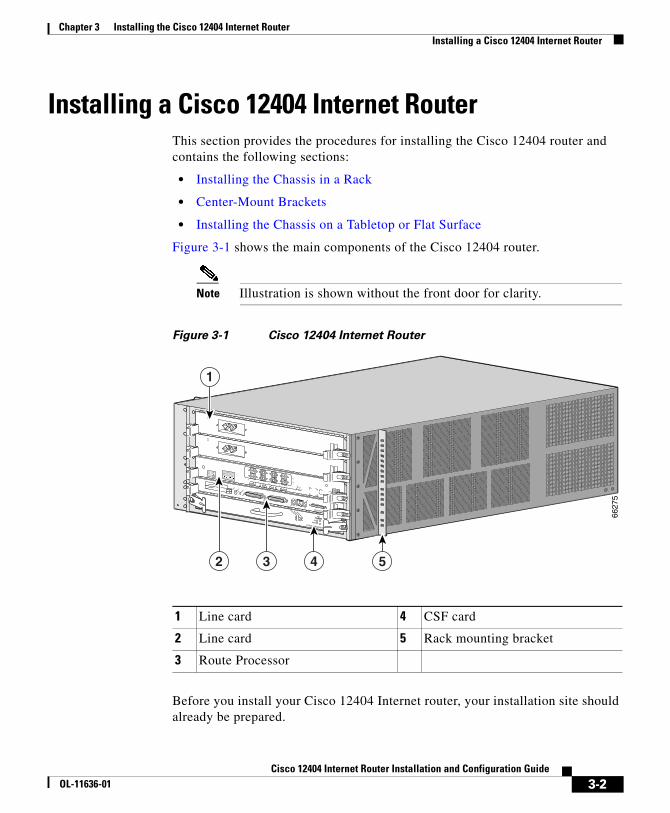
Figure 3-1 shows the main components of the Cisco 12404 router.
Note Illustration is shown without the front door for clarity.
Figure 3-1 Cisco 12404 Internet Router
Before you install your Cisco 12404 Internet router, your installation site should already be prepared.
1 Line card 4 CSF card
2 Line card 5 Rack mounting bracket
3 Route Processor
CONSOLIDATED SWITCH FABRIC
CRITICALMAJOR
MINOR
MBUS
FAILENABLE
ALARM FABRIC
10
23
40C48/POS-SR-SC
TX
RX
ACTIVE
CARRIER
RX PKT
CLASS 1 LASER PRODUCTLASERPRODUKT DER KLASSE 1PRODUIT LASER DE CLASSE 1PRODUCTO LASER DE CLASSE 1
CLEANCONNECTORWITH ALCOHOLWIPES BEFORECONNECTING
SLOT-0
GIGABIT ROUTE PROCESSOR
SLOT-1
COLL
LINK
TX
RX
RJ-45
MII
RESET
AUX
EJECT
CONSOLE
6627
5
1
5432
3-2Cisco 12404 Internet Router Installation and Configuration Guide
OL-11636-01
Chapter 3 Installing the Cisco 12404 Internet RouterInstalling a Cisco 12404 Internet Router
Ensure that you have considered the following before you install the router:
• Mounted at the left side of the chassis is the fan tray, the exhaust vents should not be blocked.
• Facing the rear of the router, mounted on the left side is the air filter; air flow to the air filter should not be blocked.
• 24 inches (61 centimeters) of clearance in front of the chassis may be needed for working with line cards, attaching Network Interface Cables (NICs), the CSF or the RP.
• Location is temperature-controlled, air-conditioned and dust-free.
• Power cables and power supplies have been checked for compatibility with your power service.
• Labels on the equipment have been checked to ensure that the power service at your site is suitable for the Cisco 12404 router.
Warning Do not mix power supply input types in the Cisco 12404 router. All power supplies installed in a router must be either AC PEMs or DC PEMs.
• AC and DC power source voltage receptacles are easy to reach.
Rack-Mounting Bracket InstallationMounting brackets are shipped with every Cisco 12404 router, these brackets are optional; you can install the Cisco 12404 router in the rack without using rack mounting brackets.
Tools Needed
You need the following items to install the optional rack-mounting brackets.
• Number 2 Phillips screwdriver
• Tape measure (optional)
• Level (optional)
3-3Cisco 12404 Internet Router Installation and Configuration Guide
OL-11636-01
Chapter 3 Installing the Cisco 12404 Internet RouterInstalling a Cisco 12404 Internet Router
Rack-Mounting Bracket Installation
The mounting brackets temporarily bear the weight of the router while it is being positioned in the rack for permanent installation. These brackets can be left in place following router installation.
Two or more people should install the router to minimize the risk of personal injury and damage to the equipment.
Installing the mounting brackets is presented in this section.
Step 1 Measure and mark the hole at the same height on both the left and right rack rails.
Step 2 Hold the right bracket against the right mounting rail and align the bottom screw hole in the bracket with the marked screw hole.
Step 3 While supporting the bracket against the mounting rail with one hand, use the other hand to insert a screw through a hole in the rack-mounting bracket.
Step 4 Use your fingers to tighten the screw.
Step 5 Insert a second screw in the top hole in the bracket and finger tighten the screw.
Step 6 Mount the left rack-mounting bracket the same as you mounted the right bracket.
Step 7 Measure the two brackets to ensure they are positioned at the same height.
Step 8 Use a level to ensure the tops of the two brackets are level, or use a measuring tape to ensure that each bracket is the same distance from the top of both rack rails.
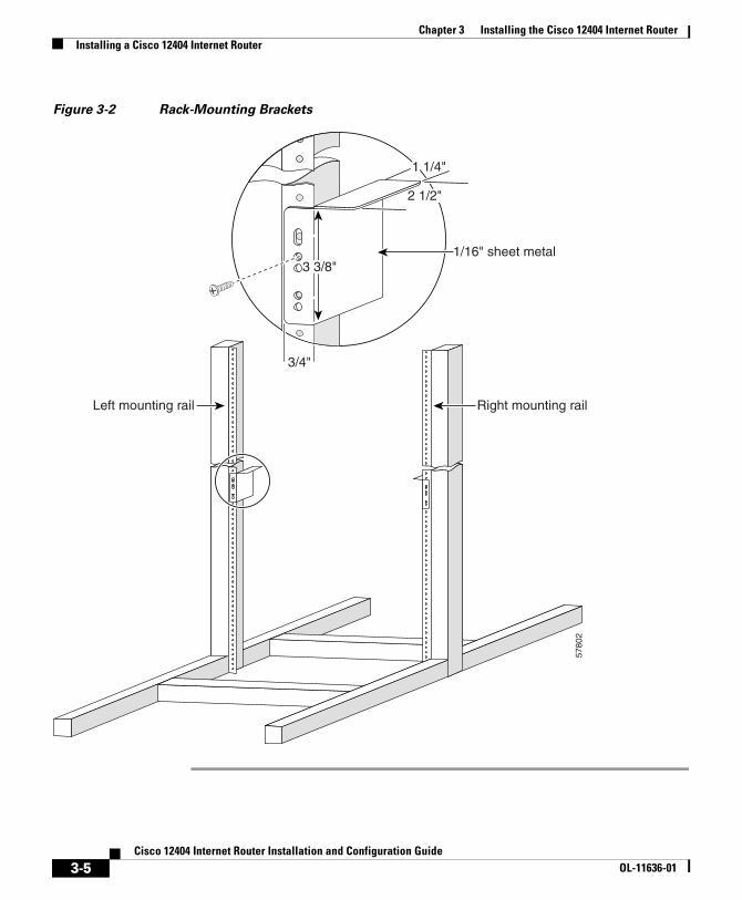
Step 9 Use a screwdriver to tighten all the screws (Figure 3-2).
3-4Cisco 12404 Internet Router Installation and Configuration Guide
OL-11636-01
Chapter 3 Installing the Cisco 12404 Internet RouterInstalling a Cisco 12404 Internet Router
Figure 3-2 Rack-Mounting Brackets
5780
2
3/4"
1 1/4"
2 1/2"
3 3/8"1/16" sheet metal
Left mounting rail Right mounting rail
3-5Cisco 12404 Internet Router Installation and Configuration Guide
OL-11636-01
Chapter 3 Installing the Cisco 12404 Internet RouterInstalling a Cisco 12404 Internet Router
Installing the Chassis in a RackInstalling the Cisco 12404 router in a rack is presented in this section. It is recommended that two people perform the following steps, to mount the chassis in a rack.
This procedure assumes you have unpacked the router using the “Cisco 12404 router Unpacking Instructions” document number 78-13618-01, posted on the outside of the shipping container.
Step 1 Move the router as close to the installation location as possible without interfering with the installation process
Step 2 One person should grasp the front and the other person grasp the rear of the chassis, bending your knees as you lift the chassis off of the pallet and position the chassis in the rack.
Step 3 If a third person is needed, have that person install the screws to secure the chassis to the rack.
Step 4 Look at the bottom mounting holes on the chassis. Align one of the holes with a mounting hole in the rack.
Step 5 Install one of the mounting screws provided.
Step 6 On the other side of the chassis adjust the position of the chassis so that the same mounting hole in the bottom group of mounting holes is aligned with a hole in the rack.
Step 7 Install one of the mounting screws provided.
Step 8 Repeat Step 4 through Step 8 for additional mounting holes.
Step 9 Use a screwdriver to tighten all the screws.
Center-Mount BracketsIf you plan to install the Cisco 12404 router in the center-mount position, you must first install the center-mount brackets on the equipment rack rails, then secure the chassis to the center-mount brackets.
3-6Cisco 12404 Internet Router Installation and Configuration Guide
OL-11636-01
Chapter 3 Installing the Cisco 12404 Internet RouterInstalling a Cisco 12404 Internet Router
The optional center-mount bracket installation kit ships in an accessories box included in the Cisco 12404 router shipping container. If any parts are missing, contact a Cisco service representative for assistance.
Required Tools
You need the following items to install the optional center-mount brackets.
• Number 2 Phillips screwdriver
• Tape measure (optional)
• Level (optional)
Center-Mount Brackets
Installation instructions using the optional center-mount brackets are presented in the following steps.
Step 1 Measure and mark the hole at the same height on both the left and right posts.
Step 2 Hold the right bracket against the right rack rail and align the bottom screw hole in the bracket with the marked screw hole.
Step 3 While supporting the bracket against the rack rail with one hand, use the other hand to insert a screw through a hole in the center-mount bracket that aligns with a hole on the rack rail.
Step 4 Use your fingers to tighten the screw.
Step 5 Insert a second screw in the top hole in the bracket and finger tighten the screw.
Step 6 Use a screwdriver to tighten all the screws (Figure 3-3).
3-7Cisco 12404 Internet Router Installation and Configuration Guide
OL-11636-01
Chapter 3 Installing the Cisco 12404 Internet RouterInstalling a Cisco 12404 Internet Router
Figure 3-3 Center-Mount Brackets
Step 7 Mount the left center-mount bracket so that it is at the same height as the right bracket.
Step 8 Use a level to ensure the two brackets are level; or use a measuring tape to ensure the both center-mount brackets are the same distance from the top of both rack mounting rails.
Step 9 Use a screwdriver to tighten all the screws.
6628
6
CONSOLIDATED SWITCH FABRIC
CRITICALMAJOR
MINOR
MBUS
FAILENABLE
ALARM FABRIC
10
23
40C48/POS-SR-SC
TX
RX
ACTIVE
CARRIER
RX PKT
CLASS 1 LASER PRODUCTLASERPRODUKT DER KLASSE 1PRODUIT LASER DE CLASSE 1PRODUCTO LASER DE CLASSE 1
CLEANCONNECTORWITH ALCOHOLWIPES BEFORECONNECTING
SLOT-0
GIGABIT ROUTE PROCESSOR
SLOT-1
COLL
LINK
TX
RX
RJ-45
MII
RESET
AUX
EJECT
CONSOLE
1
3-8Cisco 12404 Internet Router Installation and Configuration Guide
OL-11636-01
Chapter 3 Installing the Cisco 12404 Internet RouterInstalling a Cisco 12404 Internet Router
Installing the Chassis on a Tabletop or Flat SurfaceInstalling the Cisco 12404 router on a tabletop or stable flat surface is presented in the following steps.
Step 1 Move the Cisco 12404 router as close to the installation location as possible.
Step 2 With one person positioned at the front and rear of the chassis, lift the chassis off of the pallet and position the chassis on the flat surface.
Step 3 Secure the chassis to the flat surface to ensure it does not fall off.
You can use the same mounting hardware that secured your router to the shipping pallet to secure the chassis to a flat surface.
Supplemental Unit Bonding and Grounding GuidelinesIf you are not installing the Cisco 12404 router in a NEBS environment, you can choose to bypass these guidelines and rely on the safety earth ground connection supplied via the 5-15 15A North American plug to the AC power entry modules (PEMs).
Bonding and grounding receptacles are intended to satisfy the Telcordia NEBS requirements for supplemental bonding and grounding connections. The Cisco 12404 router chassis requires a safety earth ground connection as part of the power cabling to the router (Figure 3-4).
3-9Cisco 12404 Internet Router Installation and Configuration Guide
OL-11636-01
Chapter 3 Installing the Cisco 12404 Internet RouterInstalling a Cisco 12404 Internet Router
Figure 3-4 Supplemental Bonding and Grounding Port for NEBS
Compliance
We strongly recommend that you connect the central office (CO) ground system or interior equipment grounding system to the chassis. Grounding to the CO system or your interior equipment grounding system meets the network equipment building system (NEBS) bonding and grounding requirement.
To meet this requirement, crimp a dual-hole lug to #6 AWG cable and connect the lug to the chassis using two 6.3 mm (M6) screws (see Figure 3-4).
Note The spacing between the holes on the lug is 0.63 inch (16 mm). A dual-hole lug meeting these specifications can be ordered directly from Cisco (Part Number 32-0607-01).
CONSOLIDATED SWITCH FABRIC
CRITICALMAJOR
MINOR
MBUS
FAILENABLE
ALARM FABRIC
10
23
40C48/POS-SR-SC
TX
RX
ACTIVE
CARRIER
RX PKT
CLASS 1 LASER PRODUCTLASERPRODUKT DER KLASSE 1PRODUIT LASER DE CLASSE 1PRODUCTO LASER DE CLASSE 1
CLEANCONNECTORWITH ALCOHOLWIPES BEFORECONNECTING
SLOT-0
GIGABIT ROUTE PROCESSOR
SLOT-1
COLL
LINK
TX
RX
RJ-45
MII
RESET
AUX
EJECT
CONSOLE
6624
5
3-10Cisco 12404 Internet Router Installation and Configuration Guide
OL-11636-01
Chapter 3 Installing the Cisco 12404 Internet RouterConnecting RP and Line Card Cables
Connecting RP and Line Card CablesTo connect RP and line card cables to the router (Figure 3-5):
Step 1 Attach an ESD-preventive strap to yourself and to either the chassis, or to a bare metal surface.
Figure 3-5 RP and Line Card Cable-Management Brackets
Step 2 Proceeding from left to right identify the network interface cables (NIC) that attach to the RP or line card. See Figure 3-5.
Step 3 Carefully route the identified NIC through the cable-management tray and over to the card interface port; do this for one NIC at a time.
Step 4 Proceeding from left to right identify the NIC that connects to each card port and connect the NIC to the RP or line card port.
Step 5 Proceeding from left to right carefully wrap the NIC using the velcro straps.
OC-12/STM-4 POS
ACTIVE
0 CARRIER
RX CELL
ACTIVE
0 CARRIER
RX CELL
ACTIVE
0 CARRIER
RX CELL
ACTIVE
CARRIER
RX CELL
5780
3
OC-12/STM-4 POS
ACTIVE
0 CARRIER
RX CELL
ACTIVE
0 CARRIER
RX CELL
ACTIVE
0 CARRIER
RX CELL
ACTIVE
CARRIER
RX CELL
Line cardcable management
bracket
Networkinterfacecables
Velcrostrap
3-11Cisco 12404 Internet Router Installation and Configuration Guide
OL-11636-01
Chapter 3 Installing the Cisco 12404 Internet RouterConnecting RP and Line Card Cables
Caution Carefully adjust the interface cable in the RP or line card cable-management bracket to prevent any kinks or sharp bends in the interface cable. Kinks and sharp bends can destroy or degrade the ability of the optical fiber to propagate the signal-encoded beam of light accurately from one end of the cable to the other. Also, allow adequate strain relief in the interface cable.
Step 6 Route the NIC across the cable-management bracket.
Step 7 Route the cable to the chassis cable-management bracket mounted to the left side of the chassis (Figure 3-6).
• Use the screws packaged with the chassis cable management bracket kit.
Figure 3-6 Chassis Cable-Management Bracket
CONSOLIDATED SWITCH FABRIC
CRITICALMAJOR
MINOR
MBUS
FAILENABLE
ALARM FABRIC
10
23
40C48/POS-SR-SC
TX
RX
ACTIVE
CARRIER
RX PKT
CLASS 1 LASER PRODUCTLASERPRODUKT DER KLASSE 1PRODUIT LASER DE CLASSE 1PRODUCTO LASER DE CLASSE 1
CLEANCONNECTORWITH ALCOHOLWIPES BEFORECONNECTING
SLOT-0
GIGABIT ROUTE PROCESSOR
SLOT-1
COLL
LINK
TX
RX
RJ-45
MII
RESET
AUX
EJECT
CONSOLE
6627
6
3-12Cisco 12404 Internet Router Installation and Configuration Guide
OL-11636-01
Chapter 3 Installing the Cisco 12404 Internet RouterConnecting to the Console Port and Auxiliary Ports
Connecting to the Console Port and Auxiliary PortsThis section provides the information for connecting the console to the router. Both Data Set Ready (DSR) and Data Carrier Detect (DCD) signals are active when the system is running. The console port does not support modem control or hardware flow control. The console port requires a straight-through EIA/TIA-232 cable.
GRP Console and Auxiliary PortsThis section provides connection equipment and pin designation information for the console and auxiliary ports on the GRP. There are several models of the GRP that can be used with the Cisco 12404 router: GRP=, GRP-B=, and GRP-C=.
Note To comply with Telcordia GR-1089 NEBS standard for electromagnetic compatibility and safety, connect all console, auxiliary, and Ethernet interfaces only to intrabuilding or nonexposed wiring or cabling. The intrabuilding cable must be shielded and the shield must be grounded at both ends.
The GRP-C= does not require shielded cables for Class B, EMI compliance.
Note To properly maintain Class B, EMI compliance, you must use shielded cables on the console and auxiliary ports of the GRP= and GRP-B=.
The GRP has two EIA/TIA-232 ports:
• DCE DB-25 receptacle for connecting a console terminal, and
• DTE DB-25 plug for connecting other DTE devices
The DCE-mode auxiliary console port is a DCE- DB-25 and receptacle is used for connecting a console terminal, which you will need to configure the Cisco 12404 router (Figure 3-7).
3-13Cisco 12404 Internet Router Installation and Configuration Guide
OL-11636-01
Chapter 3 Installing the Cisco 12404 Internet RouterConnecting to the Console Port and Auxiliary Ports
Figure 3-7 GRP Console DCE and Auxiliary DTE Port Connections
The DTE-mode auxiliary port is a DTE DB-25 plug for connecting a modem or other DCE device (such as a channel service unit/data service unit (CSU/DSU) or another router) to the Cisco 12404 router.
Note The console and auxiliary ports are asynchronous serial ports; any devices connected to these ports must be capable of asynchronous transmission. (Asynchronous is the most common type of serial device; for example, most modems are asynchronous devices.)
Check your terminal’s documentation to determine the baud rate of the terminal you plan to use. If your documentation does not specify settings use the following terminal settings.
1. Baud to 9600
2. Data bits to 8
3. Parity to no parity
4. Stop bits to 2
You must use an EIA/TIA-232 DCE console cable to connect the terminal to the console port.
SLOT-0
SLOT-1
CO
LL
LINK
TX
RX
RJ-45
MII
RESET
AUX
EJECT
H10
735
Modem
Console terminal
Auxiliaryport
DB-25 female
DB-25 male
Consoleport
GRP
3-14Cisco 12404 Internet Router Installation and Configuration Guide
OL-11636-01
Chapter 3 Installing the Cisco 12404 Internet RouterConnecting to the Console Port and Auxiliary Ports
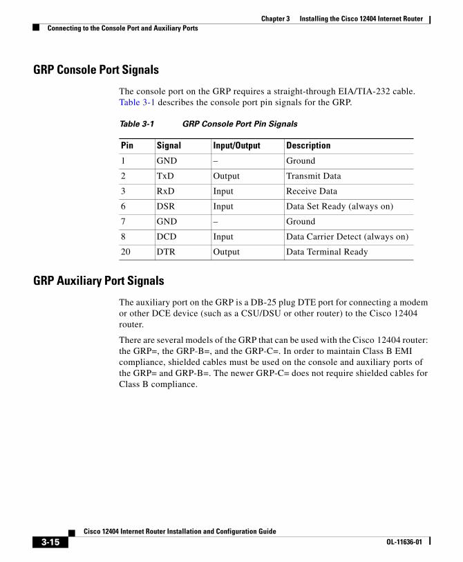
GRP Console Port Signals
The console port on the GRP requires a straight-through EIA/TIA-232 cable. Table 3-1 describes the console port pin signals for the GRP.
GRP Auxiliary Port Signals
The auxiliary port on the GRP is a DB-25 plug DTE port for connecting a modem or other DCE device (such as a CSU/DSU or other router) to the Cisco 12404 router.
There are several models of the GRP that can be used with the Cisco 12404 router: the GRP=, the GRP-B=, and the GRP-C=. In order to maintain Class B EMI compliance, shielded cables must be used on the console and auxiliary ports of the GRP= and GRP-B=. The newer GRP-C= does not require shielded cables for Class B compliance.
Table 3-1 GRP Console Port Pin Signals
Pin Signal Input/Output Description
1 GND – Ground
2 TxD Output Transmit Data
3 RxD Input Receive Data
6 DSR Input Data Set Ready (always on)
7 GND – Ground
8 DCD Input Data Carrier Detect (always on)
20 DTR Output Data Terminal Ready
3-15Cisco 12404 Internet Router Installation and Configuration Guide
OL-11636-01
Chapter 3 Installing the Cisco 12404 Internet RouterConnecting to the Console Port and Auxiliary Ports
The auxiliary port is located above the console port on the GRP card. The auxiliary port supports hardware flow control and modem control. An example of a modem connection is shown in Figure 3-7. Auxiliary port signals are listed in Table 3-2.
Table 3-2 GRP Auxiliary Port Signals
Pin Signal Input/Output Description
1 Signal Ground – Signal Ground
2 TxD Input Transmit Data
3 RxD Output Receive Data
4 RTS Input Request To Send (used for hardware flow control)
5 CTS Output Clear To Send (used for hardware flow control)
6 DSR Output Data Set Ready
7 Signal Ground – Signal Ground
8 CD Output Carrier Detect (used for modem control)
20 DTR Input Data Terminal Ready (used for modem control only)
22 RING Output Ring
3-16Cisco 12404 Internet Router Installation and Configuration Guide
OL-11636-01
Chapter 3 Installing the Cisco 12404 Internet RouterConnecting to the Console Port and Auxiliary Ports
PRP Console and Auxiliary PortsThe system console port on the PRP is a DCE RJ-45 receptacle for connecting a data terminal, which you must configure. The console port is labeled Console, as shown in Figure 3-8. Before connecting the console port, check your terminal’s documentation to determine the baud rate of the terminal you plan to use.
Note To comply with Telcordia GR-1089 NEBS standard for electromagnetic compatibility and safety, connect all console, auxiliary, Ethernet, and BITS (PRP2) interfaces only to intrabuilding or nonexposed wiring or cabling. The intrabuilding cable must be shielded and the shield must be grounded at both ends.
Check your terminal’s documentation to determine the baud rate of the terminal you plan to use. If your documentation does not specify settings use the following terminal settings:
1. Baud to 9600
2. Data bits to 8
3. Parity to no parity
4. Stop bits to 2
The console port requires a rollover RJ-45 cable.
3-17Cisco 12404 Internet Router Installation and Configuration Guide
OL-11636-01
Chapter 3 Installing the Cisco 12404 Internet RouterConnecting to the Console Port and Auxiliary Ports
Figure 3-8 PRP Console and Auxiliary Port Connections
Note The console and auxiliary ports are both asynchronous serial ports; any devices connected to these ports must be capable of asynchronous transmission. (Asynchronous is the most common type of serial device; for example, most modems are asynchronous devices.)
PRP Console Port Signals
The console port on the PRP is a DCE RJ-45 receptacle. Table 3-3 lists the signals used on this port.
1 Modem 4 Auxiliary port
2 Console terminal 5 Console port
3 RJ-45 Ethernet cables
7069
2
RX
TX
PRIMARY
SLOT-1
SLOT-0
LINK EN
RX
TX
ETH
1E
TH 0
AUX
CO
NSO
LE
LINK
PRIMARY
EN
1
3
4
5
2
3-18Cisco 12404 Internet Router Installation and Configuration Guide
OL-11636-01
Chapter 3 Installing the Cisco 12404 Internet RouterConnecting to the Console Port and Auxiliary Ports
PRP Auxiliary Port Signals
The auxiliary port on the PRP is a DTE, RJ-45 plug for connecting a modem or other DCE device (such as a CSU/DSU or another router) to the router. The port is labeled Aux, as shown in Figure 3-8. The asynchronous auxiliary port supports hardware flow control and modem control. Table 3-4 lists the signals used on the auxiliary port.
Table 3-3 PRP Console Port Signals
Console Port Pin Signal Input/Output Description
11
1. These pins are not connected.
— — —
2 DTR Output Data Terminal Ready
3 TxD Output Transmit Data
4 GND — Signal Ground
5 GND — Signal Ground
6 RxD Input Receive Data
7 DSR Input Data Set Ready
81 — — —
Table 3-4 PRP Auxiliary Port Signals
Auxiliary Port Pin Signal Input/Output Description
1 RTS Output Request To Send
2 DTR Output Data Terminal Ready
3 TxD Output Transmit Data
4 GND — Signal Ground
5 GND — Signal Ground
6 RxD Input Receive Data
7 DSR Input Data Set Ready
8 CTS Input Clear To Send
3-19Cisco 12404 Internet Router Installation and Configuration Guide
OL-11636-01
Chapter 3 Installing the Cisco 12404 Internet RouterConnecting to the Console Port and Auxiliary Ports
Installing a Flash Memory CardBy default, a Flash memory card containing a valid Cisco IOS software image is inserted in bottom slot, PCMCIA slot 0 before the router is shipped.
Note PCMCIA slot 0 is the bottom slot and slot 1 is the top slot. Both Flash memory card slots on each RP can be used at the same time.
The software configuration register is set to 0x0102, which causes the router to boot automatically from the Cisco IOS software image stored on the Flash memory card.
• The Flash memory card that shipped with your system is installed in the bottom slot, PCMCIA slot 0 of the RP. See Figure 3-9.
Figure 3-9 Flash Memory Card Slots
Ensure that a console terminal is connected to the RP console port and turned on, or that you have a remote login to the router from another device through a telnet session.
SLOT-0
SLOT-1
RESET
AUX
EJECT
5708
0
3-20Cisco 12404 Internet Router Installation and Configuration Guide
OL-11636-01
Chapter 3 Installing the Cisco 12404 Internet RouterConnecting to the Console Port and Auxiliary Ports
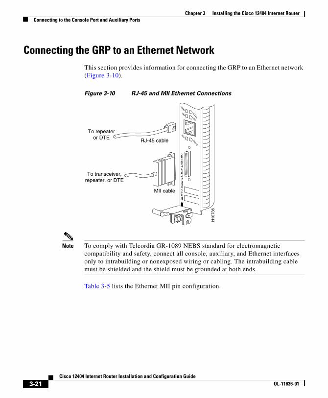
Connecting the GRP to an Ethernet NetworkThis section provides information for connecting the GRP to an Ethernet network (Figure 3-10).
Figure 3-10 RJ-45 and MII Ethernet Connections
Note To comply with Telcordia GR-1089 NEBS standard for electromagnetic compatibility and safety, connect all console, auxiliary, and Ethernet interfaces only to intrabuilding or nonexposed wiring or cabling. The intrabuilding cable must be shielded and the shield must be grounded at both ends.
Table 3-5 lists the Ethernet MII pin configuration.
RJ-45 cable
To repeateror DTE
H10
736
MII cable
To transceiver,repeater, or DTE
GIG
AB
IT R
OU
TE
PRO
CE
SSOR
CO
LL
LINK
TX
RX
RJ-45
MII
3-21Cisco 12404 Internet Router Installation and Configuration Guide
OL-11636-01
Chapter 3 Installing the Cisco 12404 Internet RouterConnecting to the Console Port and Auxiliary Ports
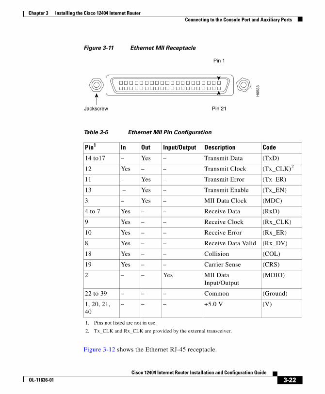
Figure 3-11 Ethernet MII Receptacle
Figure 3-12 shows the Ethernet RJ-45 receptacle.
Table 3-5 Ethernet MII Pin Configuration
Pin1
1. Pins not listed are not in use.
In Out Input/Output Description Code
14 to17 – Yes – Transmit Data (TxD)
12 Yes – – Transmit Clock (Tx_CLK)2
2. Tx_CLK and Rx_CLK are provided by the external transceiver.
11 – Yes – Transmit Error (Tx_ER)
13 – Yes – Transmit Enable (Tx_EN)
3 – Yes – MII Data Clock (MDC)
4 to 7 Yes – – Receive Data (RxD)
9 Yes – – Receive Clock (Rx_CLK)
10 Yes – – Receive Error (Rx_ER)
8 Yes – – Receive Data Valid (Rx_DV)
18 Yes – – Collision (COL)
19 Yes – – Carrier Sense (CRS)
2 – – Yes MII Data Input/Output
(MDIO)
22 to 39 – – – Common (Ground)
1, 20, 21, 40
– – – +5.0 V (V)
Jackscrew Pin 21
Pin 1
H65
38
3-22Cisco 12404 Internet Router Installation and Configuration Guide
OL-11636-01
Chapter 3 Installing the Cisco 12404 Internet RouterConnecting to the Console Port and Auxiliary Ports
Figure 3-12 Ethernet RJ-45 Receptacle
Ethernet RJ-45 Receptacle Pin Configuration
The pin configuration of the female RJ-45 receptacle on the Ethernet port follows in Table 3-6.
Warning The ports labeled Ethernet, 10BASE T, Token Ring, Console, and AUX are safety extra-low voltage (SELV) circuits. SELV circuits should only be-connected to other SELV circuits. Because the basic line interface (BRI) circuits are treated like telephone-network voltage, avoid connecting the SELV circuit to the telephone network voltage (TNV) circuits.
3-23Cisco 12404 Internet Router Installation and Configuration Guide
OL-11636-01
Chapter 3 Installing the Cisco 12404 Internet RouterConnecting to the Console Port and Auxiliary Ports
Connecting the PRP to an Ethernet NetworkThis section provides information for connecting the GRP to an Ethernet network.
There are two RJ-45 Ethernet interface receptacles on the PRP, providing media-dependent interface (MDI) Ethernet ports. These connections support IEEE 802.3 and IEEE 802.3u interfaces compliant with 10BASE-T and 100BASE-TX standards. The transmission speed of the Ethernet ports is auto-sensing by default and is user configurable.
The RJ-45 receptacles on the PRP provide two physical connection options for Ethernet interfaces. RJ-45 cables are not available from Cisco Systems; they are available from outside commercial cable vendors. To connect cables to the PRPs Ethernet interfaces (ports labeled ETH0 and ETH1), attach the Category 5 UTP cable directly to a RJ-45 receptacle on the PRP.
The Ethernet interfaces on the PRP are end-station devices, not repeaters; therefore, you must connect an Ethernet interface to a repeater or hub.
Note Only connect cables that comply with EIA/TIA-568 standards. (See Table 3-8 and Table 3-9 for cable recommendations and specifications.)
Note To comply with Telcordia GR-1089 NEBS standard for electromagnetic compatibility and safety, connect all console, auxiliary, Ethernet, and BITS (PRP2) interfaces only to intrabuilding or nonexposed wiring or cabling. The intrabuilding cable must be shielded and the shield must be grounded at both ends.
Caution The Ethernet ports are primarily used as a Telnet port into the Cisco 12000 series router, and for booting or accessing Cisco IOS software images over a network to which an Ethernet port is directly connected. Cisco Express Forwarding (CEF) functions are switched off by default for security reasons. Cisco strongly cautions you to consider the security implications of switching on CEF routing functions on these ports.
3-24Cisco 12404 Internet Router Installation and Configuration Guide
OL-11636-01
Chapter 3 Installing the Cisco 12404 Internet RouterConnecting to the Console Port and Auxiliary Ports
Figure 3-13 is an example of the functionality of an Ethernet port. In this example, you cannot access Network 2.0.0.0 through the Ethernet port (ETH0) on the PRP in router A; you can only access the hosts and router C, which are in Network 1.0.0.0. (See dotted arrows in Figure 3-13.)
To access Network 2.0.0.0 from router A, you must use an interface port on one of your line cards (in this example, a Packet-over-SONET (POS) line card in router A) to go through router B, through router C, and into Network 2.0.0.0. (See solid arrows in Figure 3-13.)
Figure 3-13 Using the Ethernet Port on the PRP
PRP Ethernet Connections
Figure 3-14 shows a PRP RJ-45 receptacle and cable connectors. The RJ-45 connection does not require an external transceiver. The RJ-45 connection requires Category 5 unshielded twisted-pair (UTP) cables, which are not available from Cisco Systems, but are available from commercial cable vendors. Table 3-7 lists the port pinouts for the RJ-45 receptacle.
Router A(Cisco 12000 series)
Router B(Cisco 7500 series)
Router C(Cisco 7500 series)
POS
EO
Host A
Network 1.0.0.0
EO
Host B
S67
55
Host A
Network 2.0.0.0
3-25Cisco 12404 Internet Router Installation and Configuration Guide
OL-11636-01
Chapter 3 Installing the Cisco 12404 Internet RouterConnecting to the Console Port and Auxiliary Ports
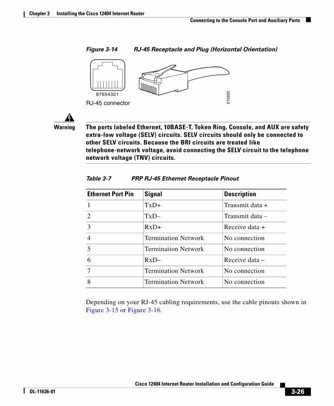
Figure 3-14 RJ-45 Receptacle and Plug (Horizontal Orientation)
Warning The ports labeled Ethernet, 10BASE-T, Token Ring, Console, and AUX are safety extra-low voltage (SELV) circuits. SELV circuits should only be connected to other SELV circuits. Because the BRI circuits are treated like telephone-network voltage, avoid connecting the SELV circuit to the telephone network voltage (TNV) circuits.
Depending on your RJ-45 cabling requirements, use the cable pinouts shown in Figure 3-15 or Figure 3-16.
Table 3-7 PRP RJ-45 Ethernet Receptacle Pinout
Ethernet Port Pin Signal Description
1 TxD+ Transmit data +
2 TxD– Transmit data –
3 RxD+ Receive data +
4 Termination Network No connection
5 Termination Network No connection
6 RxD– Receive data –
7 Termination Network No connection
8 Termination Network No connection
2102
228 7 6 5 4 3 2 1
RJ-45 connector
3-26Cisco 12404 Internet Router Installation and Configuration Guide
OL-11636-01
Chapter 3 Installing the Cisco 12404 Internet RouterConnecting to the Console Port and Auxiliary Ports
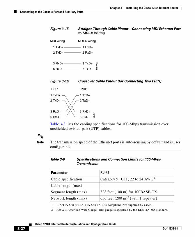
Figure 3-15 Straight-Through Cable Pinout—Connecting MDI Ethernet Port
to MDI-X Wiring
Figure 3-16 Crossover Cable Pinout (for Connecting Two PRPs)
Table 3-8 lists the cabling specifications for 100-Mbps transmission over unshielded twisted-pair (UTP) cables.
Note The transmission speed of the Ethernet ports is auto-sensing by default and is user configurable.
MDI-X wiringMDI wiring
1 TxD+
2 TxD–
3 RxD+
6 RxD–
1 RxD+
2 RxD–
3 TxD+
6 TxD– H11
007
PRP
1 TxD+
2 TxD–
3 RxD+
6 RxD–
1 TxD+
2 TxD–
3 RxD+
6 RxD– 7543
1
PRP
Table 3-8 Specifications and Connection Limits for 100-Mbps
Transmission
Parameter RJ-45
Cable specification Category 51 UTP, 22 to 24 AWG2
1. EIA/TIA-568 or EIA-TIA-568 TSB-36 compliant. Not supplied by Cisco.
2. AWG = American Wire Gauge. This gauge is specified by the EIA/TIA-568 standard.
Cable length (max) —
Segment length (max) 328 feet (100 m) for 100BASE-TX
3-27Cisco 12404 Internet Router Installation and Configuration Guide
OL-11636-01
Chapter 3 Installing the Cisco 12404 Internet RouterConnecting to an AC Power Source
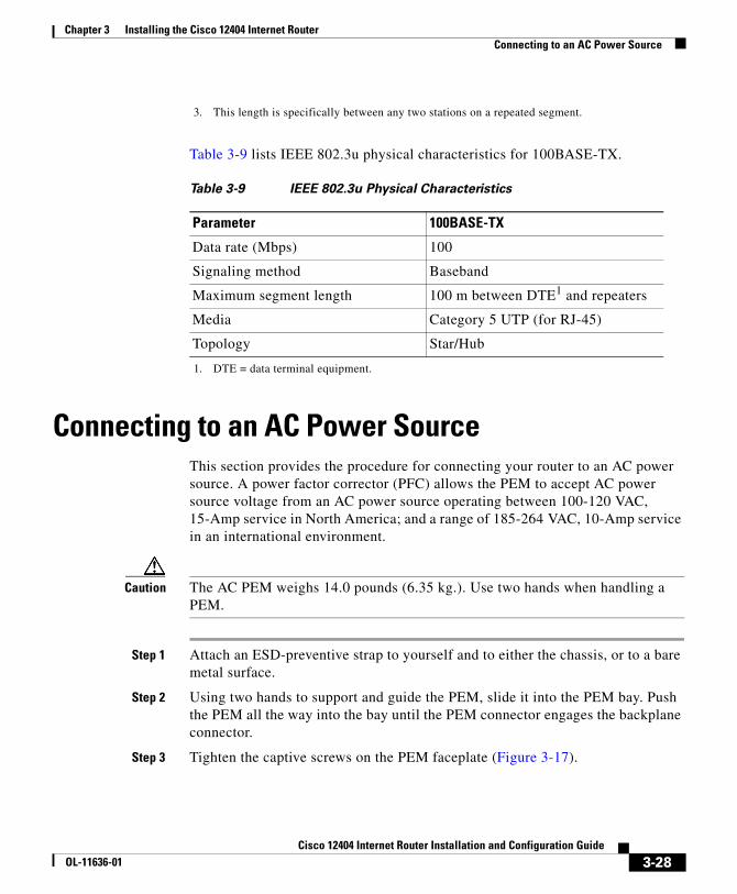
Table 3-9 lists IEEE 802.3u physical characteristics for 100BASE-TX.
Connecting to an AC Power SourceThis section provides the procedure for connecting your router to an AC power source. A power factor corrector (PFC) allows the PEM to accept AC power source voltage from an AC power source operating between 100-120 VAC, 15-Amp service in North America; and a range of 185-264 VAC, 10-Amp service in an international environment.
Caution The AC PEM weighs 14.0 pounds (6.35 kg.). Use two hands when handling a PEM.
Step 1 Attach an ESD-preventive strap to yourself and to either the chassis, or to a bare metal surface.
Step 2 Using two hands to support and guide the PEM, slide it into the PEM bay. Push the PEM all the way into the bay until the PEM connector engages the backplane connector.
Step 3 Tighten the captive screws on the PEM faceplate (Figure 3-17).
3. This length is specifically between any two stations on a repeated segment.
Table 3-9 IEEE 802.3u Physical Characteristics
Parameter 100BASE-TX
Data rate (Mbps) 100
Signaling method Baseband
Maximum segment length 100 m between DTE1 and repeaters
1. DTE = data terminal equipment.
Media Category 5 UTP (for RJ-45)
Topology Star/Hub
3-28Cisco 12404 Internet Router Installation and Configuration Guide
OL-11636-01
Chapter 3 Installing the Cisco 12404 Internet RouterConnecting to an AC Power Source
Figure 3-17 AC PEM
• All electrical connections between the power supply and the backplane are made automatically when the power supply is fully inserted in the power supply bay.
Step 4 Locate the AC power cord and remove it from its shipping packaging. Verify that the AC power cord shipped with the power supply is the correct type for your site.
Note If you have an incorrect type of power cord, contact your service representative for a replacement.
Step 5 Plug the AC power cord into the AC PEM.
Step 6 Connect the other end of the AC power cord to the AC power source outlet.
Note We recommend attaching each AC PEM to an independent power source for full redundancy. We also recommend that you use an uninterruptable power source (UPS) to protect against power failures at your site.
1 AC PEM handle 4 Power cord receptacle
2 On/Off switch 5 LEDs
3 Bail Latch 6 Captive screws
INPUTOK OUTPUT
FAIL
INPUT100-240V12A50/80HZ
OUTPUTOK
6628
9
456
1 2 3
3-29Cisco 12404 Internet Router Installation and Configuration Guide
OL-11636-01
Chapter 3 Installing the Cisco 12404 Internet RouterConnecting to an AC Power Source
Step 7 Verify that the AC power source circuit breaker servicing the AC PEM is switched on (Figure 3-18).
Caution Turn the AC PEM power switch OFF.
Figure 3-18 AC PEM LEDs
Note When operating your router on an AC power source, both PEM bays must have all AC PEMs installed to ensure compliance with regulatory EMI standards.
1 INPUT OK Green AC is present and within specified limits
2 OUTPUT OK Green Power supply module is operating normally in a powered up condition
3 OUTPUT FAIL Amber Power module is operating in a fault condition and shutdown has occurred
INPUTOK OUTPUT
FAIL
INPUT100-240V12A50/80HZ
OUTPUTOK
6629
0
INPUTOK
OUTPUTFAIL
OUTPUTOK
1 2 3
3-30Cisco 12404 Internet Router Installation and Configuration Guide
OL-11636-01
Chapter 3 Installing the Cisco 12404 Internet RouterConnecting to an AC Power Source
Powering On the RouterPower on the router by switching on all the circuit breakers and/or plug the power cord into an active power source that controls power to the router’s AC PEM or DC power distribution unit (PDU).
Note During the first-time startup, the system displays the system banner information.
Checking the Startup
Check the startup banner and displays to ensure that the system has restarted properly and that all the interfaces reinitialize properly. You should observe the power module LEDs shown in figures Figure 3-18. Also, listen for the fans in the fan tray, you should immediately hear them operating. In a noisy environment, the fans might be difficult to hear; therefore, place your hand in front of the exhaust vents at the side of the chassis to verify that the fans are operating.
Visually check the CSF LEDs, MBus LEDs on the CSF, and the RP LEDs on the RP (Figure 3-19).
RP LEDs are located at one end of the RP faceplate, near the ejector lever. Figure 3-25 shows the RP LED displays.
Table 3-10 lists the CSF LEDs.
Figure 3-19 CSF LEDs
CONSOLIDATED SWITCH FABRIC
CRITICALMAJOR
MINOR MBUS
FAIL
ENABLE
ALARM FABRIC
6624
6
CRITICALMAJOR
MINOR
MBUS
FAIL
ENABLE
ALARM FABRIC
3-31Cisco 12404 Internet Router Installation and Configuration Guide
OL-11636-01
Chapter 3 Installing the Cisco 12404 Internet RouterConnecting to an AC Power Source
Table 3-11 lists the CSF MBus alarm LEDs, and Table 3-12 lists the CSF MBus LEDs.
On the console terminal, verify that the console displays the system banner and that the system and all interfaces initialize successfully.
If the power supplies do not power up, or if the system or any interfaces do not initialize properly, see Chapter 4, “Troubleshooting the Installation.” If you are still unable to resolve the problem, contact your Cisco service representative for assistance.
Table 3-10 CSF LEDs
Switch Fabric LEDs Status Condition
CRITICAL Off Normally Off
MAJOR Off Normally Off
MINOR Off Normally Off
Table 3-11 CSF MBus Alarm LEDs
MBus Alarm LEDs Status Condition
FAIL Off Normally Off
ENABLE ON Normally On
Table 3-12 CSF MBus LEDs
MBus Fabric LEDs Status Condition
FAIL Off Normally Off
ENABLE ON Normally On
3-32Cisco 12404 Internet Router Installation and Configuration Guide
OL-11636-01
Chapter 3 Installing the Cisco 12404 Internet RouterConnecting the Router to a DC Power Source
Connecting the Router to a DC Power SourceThis section provides the procedure for connecting your router to a DC power source (Figure 3-20).
Note We recommend each DC PDU be connected to an independent power source for full redundancy. We also recommend that you use an uninterruptable power source (UPS) to protect against power failures at your site.
Figure 3-20 DC Power PEM and PDU Assembly
1 DC PDU 5 On/Off switch
2 DC (PEM) 6 PEM to PDU captive screws
3 System captive screw 7 Terminal Block
4 LEDs
INPUT– 48/60V35A
6629
5
INPUTOK OUTPUT
FAIL
OUTPUTOK
56
43
7
1 2 3
3-33Cisco 12404 Internet Router Installation and Configuration Guide
OL-11636-01
Chapter 3 Installing the Cisco 12404 Internet RouterConnecting a DC PDU and DC PEM Assembly
Connecting a DC PDU and DC PEM AssemblyEach DC PDU should be connected to separate DC sources using six threaded terminals. Two terminals for negative (source DC), two terminals for positive (source DC return), and two terminals for ground. The DC power cable leads should be 6 American Wiring Gauge (AWG) high strand count wire. The PEM accepts DC power source voltage from a dedicated 35–Amp service DC power source operating between -48 to -60 VDC.
Caution The DC PEM and DC PDU assembly weighs 14.0 pounds (6.35 kg.). Use two hands when handling the power supply.
Warning Power to your router must be Off and all cables disconnected before you install the DC power assembly. The DC PDU and DC PEM when connected, is not a hot-swappable, field replaceable unit.
Use this procedure to install the DC PEM and DC PDU in your router. The DC power module housing is located at the rear of the chassis.
Step 1 Attach an ESD-preventive strap to yourself and to either the chassis, or to a bare metal surface.
Step 2 Insert the DC power module into the power module bay at the rear of the chassis
Step 3 Press the power supply against the backplane until the connectors are seated against the backplane receptacles.
• Figure 3-21 shows the rear view of a Cisco 12404 router with the DC PDU installed.
Step 4 Tighten all of the captive screws on the faceplate.
• All electrical connections between the power supply and the backplane are made automatically when the power supply is fully inserted in the power supply bay.
3-34Cisco 12404 Internet Router Installation and Configuration Guide
OL-11636-01
Chapter 3 Installing the Cisco 12404 Internet RouterConnecting a DC PDU and DC PEM Assembly
Step 5 Use a 1/4-inch screwdriver to tighten the captive screws on the DC PDU (Figure 3-22).
Figure 3-21 DC Powered Cisco 12404 Internet Router Rear View
Figure 3-22 DC PDU Power Block
6628
8
INPUT– 48/60V35A
INPUTOK OUTPUT
FAIL
OUTPUTOK
INPUT– 48/60V35A
INPUTOK OUTPUT
FAIL
OUTPUTOK
1 Negative Terminal Port 3 Ground Terminal Port
2 Positive Terminal Port 4 Terminal Port Connector Screws
6694
9
+GND
14
2
3
3-35Cisco 12404 Internet Router Installation and Configuration Guide
OL-11636-01
Chapter 3 Installing the Cisco 12404 Internet RouterConnecting a DC PDU and DC PEM Assembly
Step 6 Secure each lead to the proper terminal port by tightening the terminal port connector screws with a 3/16-inch flat-blade screw driver.
Step 7 Verify that the DC power source circuit breaker servicing the DC PEM is switched on.
Powering On the RouterPower on the router by switching on all the circuit breakers and/or plug the power cord into an active power source that controls power to the router’s AC PEM or DC power distribution unit (PDU).
Note During the first-time startup, the system displays the system banner information.
Checking the Startup
Check the startup banner and displays to ensure that the system has restarted properly and that all the interfaces reinitialize properly. You should observe the power module LEDs shown in figures. Also, listen for the fans in the fan tray, you should immediately hear them operating. In a noisy environment, the fans might be difficult to hear; therefore, place your hand in front of the exhaust vents at the side of the chassis to verify that the fans are operating.
Visually check the CSF LEDs (Figure 3-23), MBus LEDs on the CSF, and the RP LEDs on the RP. RP LEDs are located at one end of the RP faceplate, near the ejector lever. Figure 3-25 shows the RP LED displays. Table 3-13, Table 3-14, and Table 3-15 define the LEDs.
3-36Cisco 12404 Internet Router Installation and Configuration Guide
OL-11636-01
Chapter 3 Installing the Cisco 12404 Internet RouterConnecting a DC PDU and DC PEM Assembly
Figure 3-23 CSF LEDs
On the console terminal, verify that the console displays the system banner and that the system and all interfaces initialize successfully.
Table 3-13 CSF LEDs
Switch Fabric LEDs Status Condition
CRITICAL Off Normally Off
MAJOR Off Normally Off
MINOR Off Normally Off
Table 3-14 CSF MBus Alarm LEDs
MBus Alarm LEDs Status Condition
FAIL Off Normally Off
ENABLE ON Normally On
Table 3-15 CSF MBus LEDs
MBus Fabric LEDs Status Condition
FAIL Off Normally Off
ENABLE ON Normally On
CONSOLIDATED SWITCH FABRIC
CRITICALMAJOR
MINOR MBUS
FAIL
ENABLE
ALARM FABRIC
6624
6
CRITICALMAJOR
MINOR
MBUS
FAIL
ENABLE
ALARM FABRIC
3-37Cisco 12404 Internet Router Installation and Configuration Guide
OL-11636-01
Chapter 3 Installing the Cisco 12404 Internet RouterConnecting a DC PDU and DC PEM Assembly
DC Power Entry Module LEDs
Verify the DC PEM LEDs are on and that the status is O.K (Figure 3-24).
Figure 3-24 DC PEM LEDs
1 DC PDU n/a n/a
2 DC PEM n/a n/a
3 INPUT OK Green DC is present and within specified limits
4 OUTPUT OK Green Power supply module is operating normally in a powered up condition
5 OUTPUT FAIL Amber Power module is operating in a fault condition and shutdown has occurred
INPUT– 48/60V35A
6639
9
INPUTOK OUTPUT
FAIL
OUTPUTOK
INPUTOK
OUTPUTFAIL
OUTPUTOK
3
1 2
4 5
3-38Cisco 12404 Internet Router Installation and Configuration Guide
OL-11636-01
Chapter 3 Installing the Cisco 12404 Internet RouterCisco IOS Software Configuration for the Cisco 12404 Internet Router
If the power assembly does not power up, or if the system or any interfaces do not initialize properly, see Chapter 4, “Troubleshooting the Installation,”. If you are still unable to resolve the problem, contact your Cisco service representative for assistance.
Cisco IOS Software Configuration for the Cisco 12404 Internet Router
This section provides you with the necessary information to configure your system so that it can access the network or enable other hosts in the network to access your system remotely by means of a Telnet connection.
The system startup process and a procedure for performing a basic configuration of your Cisco 12404 Internet router are presented in the following sections.
• Cisco IOS Software Images, page 3-40
• Conditions to Check before System Startup, page 3-40
• Boot Process Overview, page 3-41
• Starting the Router and Observing Initial Conditions, page 3-42
• Manually Booting the System, page 3-49
• Configuring the Router, page 3-52
• Using Flash Memory Cards in the RP, page 3-70
3-39Cisco 12404 Internet Router Installation and Configuration Guide
OL-11636-01
Chapter 3 Installing the Cisco 12404 Internet RouterCisco IOS Software Images
Cisco IOS Software ImagesA default Cisco IOS software image for your system is available through any of the following internal or external sources(Table 3-16):
Conditions to Check before System StartupThis section provides information on items to check before you startup the router.
• All cards are completely inserted into their card cage slots.
• All captive screws are tightened.
• All interface cable connections are secure.
• All the power source cables are secured to the power modules.
• All power cables are connected to the appropriate power source.
• A terminal device is connected, powered on and configured to 9600 bps, 8 data bits, no parity, and 2 stop bits (9600,8,N,2).
• A Flash memory card containing a valid Cisco IOS software image is inserted in PCMCIA slot 0 (zero).
Table 3-16 Cisco IOS Software Image Sources
Cisco Software Image Source
Onboard Flash Memory on the RP
The latest Cisco IOS software image is loaded into the Flash memory, a single inline memory module (SIMM) is preloaded at the factory before the router is shipped. The Flash memory SIMM is also referred to as nonvolatile random access memory (NVRAM). This type of memory retains its contents when you turn off system power.
Flash Memory Card A Flash memory card inserted in a PCMCIA slot on the RP, and loaded with the default software image, can serve as an external storage medium for the default Cisco IOS software image shipped with your router.
TFTP Server You can download and store a valid Cisco IOS software image via a Trivial File Transfer Protocol (TFTP) using a Telnet connection.
3-40Cisco 12404 Internet Router Installation and Configuration Guide
OL-11636-01
Chapter 3 Installing the Cisco 12404 Internet RouterBoot Process Overview
By default, the software configuration register is set to 0x0102, causing the system to boot automatically from the Cisco IOS software image stored on the Flash memory card.
Note New Flash memory cards must be formatted before you can use them.
After you start the router, if you want to format a new Flash memory card, refer to the section “Formatting a Flash Memory Card, page 3-72”.)
Boot Process OverviewThis example procedure assumes you have plugged the router into a power source and the router is running, fan tray assembly fans are audible and the fabric and alarm card ENABLED LEDs are On.
The following is an example of a typical boot process.
• The RP MBus module receives a +5 VDC voltage and starts executing MBus software.
• The RP determines the router configuration by sending a message via the alarm function on the CSF requesting all installed devices to identify themselves. Their responses provide slot numbers and card and component types. The RP and line cards are then powered up.
• The power-on-reset logic of the RP is delayed long enough to allow power and both local and CSF clocks to stabilize.
• After the power-on reset logic is released, the RP begins to execute the ROM monitor software.
• If the ROM monitor is configured to autoboot, it automatically loads and boots the Cisco IOS software.
• If the ROM monitor is not configured to autoboot, you must boot the Cisco IOS software manually. See Manually Booting the System, page 3-49.
• When the Cisco IOS software boots, it polls all other cards in the system, powers them up, and loads the Cisco IOS software they require.
3-41Cisco 12404 Internet Router Installation and Configuration Guide
OL-11636-01
Chapter 3 Installing the Cisco 12404 Internet RouterStarting the Router and Observing Initial Conditions
Starting the Router and Observing Initial ConditionsObserve the following conditions the first time you start your router.
AC PEM
When an AC PEM is seated in its bay, the On/Off switch is On and is receiving the required AC power source.
• Two Green LEDs labeled INPUT OK and OUTPUT OK are on.
• Each power supply fan is on.
• Amber LED labeled OUTPUT FAIL is off.
• All cards are fully inserted in the card and CSF cage
• All captive screws are tight
• Line card cable-management brackets are attached to their respective line cards
• Interface cables are routed neatly through the line card cable-management bracket
• Interface cables are completely seated in their line card connectors
• Interface cables are routed neatly through the chassis cable-management bracket
Caution Do not overtighten the captive screws on the cards you might strip the threads on the screw or in the insert in the component faceplate.
• PEMs are fully inserted in to each AC PEM bay or DC PDU and DC PEM bay
• PEM cables are fully connected to the PEM
• Power cables are fully connected to the PDU, the power source and are secured with appropriate strain relief.
• Empty card slots or card bays are filled with card blanks to ensure proper air flow through the chassis and electromagnetic compatibility (EMC)
Listen for the fans in the fan tray; they should be running. In a noisy environment, the fan might be difficult to hear. You should place your hand near the exhaust vents at the side of the chassis to verify that the fan is operating.
3-42Cisco 12404 Internet Router Installation and Configuration Guide
OL-11636-01
Chapter 3 Installing the Cisco 12404 Internet RouterStarting the Router and Observing Initial Conditions
RP Alphanumeric LEDs
RP LEDs are located at one end of the RP faceplate, near the ejector lever. Figure 3-25 shows the RP alphanumeric LED displays.
Figure 3-25 RP Alphanumeric LED Displays
Each four-digit display shows part of a two-line system message. During the RP boot process, the LED displays present a sequence of messages similar to that shown in Table 3-17.
Right alphanumericLED display (four digits)
Left alphanumericLED display (four digits)
5707
9Table 3-17 RP LED Display, Definition and Source
LED Display Definition Source
MROMnnnn
The MBus microcode begins to execute; nnnn is the microcode version number. For example, microcode version 1.17 displays as 0117.1
Note This display might not be visible because it occurs for only a brief time.
MBus controller
LMEMTEST
Low memory on the RP is being tested. RP ROM monitor
MEMINIT
The size of main memory on the RP is being discovered. RP ROM monitor
RPRDY
The system is operational and ready to execute basic Cisco IOS software commands at the ROM monitor prompt (rommon>).
RP ROM monitor
RPUP
A valid Cisco IOS image is running. RP IOS software
3-43Cisco 12404 Internet Router Installation and Configuration Guide
OL-11636-01
Chapter 3 Installing the Cisco 12404 Internet RouterStarting the Router and Observing Initial Conditions
GRP Interfaces Using the PRP LEDs
The RJ-45 and MII port LEDs on the GRP indicate:
• System and RP status.
• Which Flash memory card slot is active.
• Which Ethernet connection is in use.
• What is occurring on the Ethernet interface.
A successful GRP boot is indicated by the alphanumeric LED displays.
The GRP faceplate has eight device or port LED activity indicators. Each LED goes on when its corresponding PCMCIA slot is accessed.
• 4 RJ-45 Ethernet port activity LEDs. These LEDs are used only by the RJ-45 Ethernet connector, and are disabled when the MII Ethernet port is in use.
• 2 Ethernet port-selection LEDs labeled MII and RJ-45.
When the Ethernet port LEDs are lit, they identify which one of the two Ethernet connections you have selected. When the RJ-45 port is selected, that LED is on and the MII LED is Off. When the MII port is selected, that LED is On and the RJ-45 LED is Off (Figure 3-26).
PRIRP
The RP is enabled and recognized as the system primary. A valid Cisco IOS image is running.
RP IOS software
SECRP
The RP is enabled and recognized as the system secondary. A valid Cisco IOS image is running.
RP IOS software
1. The version of MBus microcode running on your system might be different.
Table 3-17 RP LED Display, Definition and Source (continued)
LED Display Definition Source
3-44Cisco 12404 Internet Router Installation and Configuration Guide
OL-11636-01
Chapter 3 Installing the Cisco 12404 Internet RouterStarting the Router and Observing Initial Conditions
Figure 3-26 RP RJ-45 and MII Ports LEDs
PRP Interfaces Using the PRP LEDs
The RJ-45 port LEDs on the PRP indicate:
• System and PRP status.
• Which Flash memory card slot is active.
• Which Ethernet connection is in use.
• What is occurring on the Ethernet interface.
A successful PRP boot is indicated by the alphanumeric LED displays.
The PRP faceplate (Figure 3-27) has 8 device or port LED activity indicators. Each LED goes on when its corresponding PCMCIA slot is accessed.
• 4 RJ-45 Ethernet port activity LEDs. These LEDs are used by the RJ-45 Ethernet connectors. Each connector includes a set of 4 LEDs that indicate link activity (LINK), port enabled (EN), data transmission (TX), and data reception (RX).
LINK Indicates link activity
COLL Indicates collision detection
TX Indicates data transmission
RX Indicates data reception
5707
5
SLOT-0
SLOT-1 COLL
LINK TX
RX RJ-45
MII
RESET
AUX
EJECT
3-45Cisco 12404 Internet Router Installation and Configuration Guide
OL-11636-01
Chapter 3 Installing the Cisco 12404 Internet RouterStarting the Router and Observing Initial Conditions
• 2 Ethernet port-selection LEDs labeled PRIMARY.These two LEDs, when on, identify which of the two Ethernet connections are selected. Because both ports are supported on the PRP, the LED on port ETH0 is always on. The ETH1 LED goes on when it is selected.
Figure 3-27 PRP LEDs
Line Card Interfaces Using the Line Card LEDs
During the line card boot process, which occurs immediately after the RP boot process, observe the alphanumeric LED displays on each line card (Table 3-18).
The alphanumeric LED displays on a line card are located in the same place as on the RP. The system attempts to boot identical line cards in parallel. Further, the system boots line cards as soon as they are powered on and become available for backup.
LINK Indicates link activity
EN Indicates the port is enabled
TX Indicates data transmission
RX Indicates data reception
RX
TX
PRIMARY
SLOT-1
SLOT-0
LINK
EN
RX
TX
ETH 1ETH 0
LINK
PRIMARY
EN
7069
3
3-46Cisco 12404 Internet Router Installation and Configuration Guide
OL-11636-01
Chapter 3 Installing the Cisco 12404 Internet RouterStarting the Router and Observing Initial Conditions
Table 3-18 Line Card LED Display, Definition, and Source
LED Display1
1. The LED sequence shown in Table 3-18 might occur too quickly for you to view. The sequence in this table is provided as an example of how the line cards should function at startup.
Definition Source
MROMnnnn
MBus microcode begins to execute; nnnn is the microcode version number. For example, microcode version 1.17 would display as 0117.2
2. The numeric display might not be visible, because it occurs for only a brief time.
MBus controller
LMEMTEST
Low memory on the line card is being tested. Line card ROM monitor
MEMINIT
Main memory on the line card is being discovered. Line card ROM monitor
ROMIGET
ROM image is being loaded into line card memory. RP Cisco IOS software
FABLWAIT
Line card is waiting for the fabric downloader to load.3
3. The fabric downloader loads the Cisco IOS software image onto the line card.
RP Cisco IOS software
FABLDNLD
Fabric downloader is being loaded into line card memory. RP Cisco IOS software
FABLSTRT
Fabric downloader is being launched. RP Cisco IOS software
FABLRUN
Fabric downloader has been launched and is running. RP Cisco IOS software
IOS DNLD
Cisco IOS software is being downloaded into line card memory.
RP Cisco IOS software
IOSSTRT
Cisco IOS software is being launched. RP Cisco IOS software
IOS UP
Cisco IOS software is running. RP Cisco IOS software
IOSRUN
Line card is enabled and ready for use. RP Cisco IOS software
3-47Cisco 12404 Internet Router Installation and Configuration Guide
OL-11636-01
Chapter 3 Installing the Cisco 12404 Internet RouterStarting the Router and Observing Initial Conditions
Tip When you start an unconfigured system for the first time, the console screen displays a system banner and then automatically starts the System Configuration Dialogue.
Observe the Cisco IOS banner on the console screen. If a Flash memory card containing a valid Cisco IOS software image is inserted in PCMCIA slot 0 and the software configuration register is set to 0x0102 (the factory default setting), the router automatically boots using this image.
As the router boots the Cisco IOS software image, the console screen displays a system banner similar to the following.
Cisco Internetwork Operating System SoftwareIOS (tm) GS Software (IR-P-M), Experimental Version 12.0(20020120:204554) [Krathay]Copyright (c) 1986-2002 by cisco Systems, Inc.Compiled Sat 20-Apr-02 18:34 by kragily...
Note The system banner that appears depends on the image version of the Cisco IOS software that the system is running.
If the ROM monitor prompt (rommon>) appears on the system console, your router did not find a valid system image, or the boot sequence was otherwise interrupted, and the system entered read-only memory (ROM) monitor mode.
To boot a Cisco IOS software image manually, enter the boot command on the system console.
For information on using one of the various forms of the boot command, see the following sections.
• Booting from the Cisco IOS Software Image, page 3-51
• Locating a Valid Cisco IOS Software Image, page 3-50
3-48Cisco 12404 Internet Router Installation and Configuration Guide
OL-11636-01
Chapter 3 Installing the Cisco 12404 Internet RouterManually Booting the System
System Configuration Dialogue
The following information is an example of a System Configuration Dialog interactive script message you will see on the system console. This interactive script prompts you through the steps to create a router configuration database file defining basic system operation parameters.
--- System Configuration Dialog ---
Continue with configuration dialog? [yes/no]:
External Network Interface
After configuration, the RP and line cards can communicate with external networks.
You do not need to configure the network interfaces immediately, but you cannot connect to a network until you configure the interfaces for operation in your networking environment. (For configuration information, see Configuring the Router, page 3-52.)
Note The interface-specific LEDs on the line cards go on when the line card interfaces are configured.
To verify correct operation of each line card interface, complete the first-time setup procedures and configuration, then check the status of the interfaces against the LED descriptions in the configuration notes for each line card.
If the system does not complete each of the boot process steps, go to “Chapter 4, “Troubleshooting the Installation.”
Manually Booting the SystemIf your router does not find a valid system configuration image, or if you interrupt the boot sequence, the system might enter read-only memory (ROM) monitor mode and display the ROM monitor prompt (rommon>). From ROM monitor mode, you have access to a number of commands to locate and boot a valid system image.
3-49Cisco 12404 Internet Router Installation and Configuration Guide
OL-11636-01
Chapter 3 Installing the Cisco 12404 Internet RouterManually Booting the System
Locating a Valid Cisco IOS Software ImageTo locate a Cisco IOS software image for manually booting the router from the ROM monitor prompt (rommon>), follow these steps.
Step 1 Use the ROM monitor mode dir bootflash command to examine the contents of the onboard Flash memory SIMM (NVRAM) on the RP:
rommon 1> dir bootflash:File size Checksum File name
Step 2 If the onboard Flash memory SIMM contains the desired Cisco IOS boot image, proceed to the “Booting from the Cisco IOS Software Image” section on page 3-51.
Or, Continue looking for a valid image by examining the contents of the Flash memory card in either PCMCIA slot 0 or slot 1 on the RP.
You can determine the content of the card by issuing the ROM monitor mode dir slotn: command, where n represents either 0 (slot 0) or 1 (slot 1). The following example of the command lists the contents of the Flash memory card in slot 0:
3-50Cisco 12404 Internet Router Installation and Configuration Guide
OL-11636-01
Chapter 3 Installing the Cisco 12404 Internet RouterManually Booting the System
Booting from the Cisco IOS Software ImageAfter locating a valid Cisco IOS software image, you can boot from that image manually by issuing the appropriate ROM monitor mode boot commands from Table 3-19:
Ensure that the Flash memory card inserted in PCMCIA slot 0 contains a valid Cisco IOS software image; otherwise, you could instruct the system to boot an invalid image from the Flash memory card. To examine the contents of a Flash memory card, enter the dir slotn: command.
If you did not change the contents of the software configuration register, the factory default setting of 0x0102 in the software configuration register causes the system to boot Cisco IOS software from a Flash memory card inserted in PCMCIA slot 0 the next time you boot the router.
Table 3-19 ROM Monitor Boot Commands and Description
Command Description
boot (No argument.) Boot the default image found in the onboard Flash memory SIMM. The image is loaded into the SIMM at the factory.
boot flash Attempt to boot the router using the first file found in the Flash memory card inserted in slot 0 (zero) of the RP.
boot slot0: filename Boots the router using the specified file from the Flash memory card in slot 0 of the RP.
boot slot1: filename Boots the router using the specified file from the Flash memory card in slot 1 of the RP.
boot bootflash: filename Boots the router using the specified file from the onboard Flash memory SIMM (NVRAM) on the RP.
boot tftp: filename [host]
Boots the router using the specified file from a host TFTP server in the network.
3-51Cisco 12404 Internet Router Installation and Configuration Guide
OL-11636-01
Chapter 3 Installing the Cisco 12404 Internet RouterConfiguring the Router
Configuring the RouterYou can perform a basic configuration for your router by using either the setup command automatic prompt method or the global configuration method where you enter each option and parameter manually. The configuration process is mapped into three processes:
• Before You Begin, page 3-52
• setup Command, page 3-52
• Global Configuration Mode, page 3-53
Before You BeginBefore you begin the configuration process for your router, you should have the following information onhand:
• Router interfaces
• Protocols the router is routing
• Network addresses for the protocols being configured
• Password scheme for your environment
setup CommandUsing the setup command, also known as the setup command utility. During, the first startup of an unconfigured router, the system automatically starts up the setup command utility, which enables you to begin configuring your router. The setup command utility presents a structured, interactive script that guides you through the process.
You can also invoke the setup command utility at any time by issuing the setup command at the privileged EXEC mode prompt (Filo#), which invokes the same configuration script that appears automatically during the first startup of an unconfigured router.
You can enter the setup command at any time you want to alter previously entered configuration information. The advantage in using the setup command utility is that the system uses an interactive script to guide you through the configuration
3-52Cisco 12404 Internet Router Installation and Configuration Guide
OL-11636-01
Chapter 3 Installing the Cisco 12404 Internet RouterConfiguring the Router
process. The setup command utility is described in Using the setup command, also known as the setup command utility. During, the first startup of an unconfigured router, the system automatically starts up the setup command utility, which enables you to begin configuring your router. The setup command utility presents a structured, interactive script that guides you through the process., page 3-52.
Global Configuration ModeYou can configure the router manually using the global configuration mode through the Cisco IOS command line interface (CLI). This method requires you to enter configuration commands on a line-by-line basis at the system console, without being prompted by the setup command configuration script. Global configuration mode is described in Global Configuration Mode, page 3-53.
Cisco IOS User InterfaceThe Cisco IOS software provides a command line interface that allows you to configure and manage your router. If you are unfamiliar with the Cisco IOS command line interface, you should read the “Using the Command Line Interface” chapter in the Cisco Configuration Fundamentals Configuration Guide where different command modes, context-sensitive help, and editing features are discussed.
User Interface Command Modes
The Cisco IOS user interface is organized into many different modes. The commands available to you at any given time depend on which mode you are currently in. Entering a question mark (?) at the system prompt displays a list of commands available for the current command mode.
When you start a session on the router, you begin in user mode, often called EXEC mode. Only a limited subset of the commands are available in EXEC mode. In order to have access to all commands, you must enter privileged EXEC mode. Normally, you must enter a password to enter privileged EXEC mode. From privileged EXEC mode, you can enter any EXEC command or enter global configuration mode. Most of the EXEC commands are one-time commands, such
3-53Cisco 12404 Internet Router Installation and Configuration Guide
OL-11636-01
Chapter 3 Installing the Cisco 12404 Internet RouterConfiguring the Router
as show commands, which show the current configuration status, and clear commands, which clear counters or interfaces. The EXEC commands are not saved across reboots of the router.
The configuration modes allow you to make changes to the running configuration. If you later save the configuration, these commands are stored and can be used when you reboot your router. Start at global configuration mode where you can then enter a specific mode or the system automatically enters ROM monitor mode when the router cannot boot properly.
ROM Monitor Mode
ROM monitor mode is a separate mode used when the router cannot boot properly. If your router does not find a valid system image when it is booting, or if the router configuration file is corrupt at startup, the system might enter ROM monitor mode.
User EXEC Mode
After your router boots successfully and loads the Cisco IOS software, the system software displays the user EXEC mode prompt on the system console. The user EXEC mode prompt consists of the assigned router host name plus the greater than bracket (>). The following example shows the user EXEC mode prompt for a router with the factory default name Router.
Router>
Note The default host name is router unless it has been changed during initial configuration using the setup command facility.
3-54Cisco 12404 Internet Router Installation and Configuration Guide
OL-11636-01
Chapter 3 Installing the Cisco 12404 Internet RouterConfiguring the Router
Privileged EXEC Mode
Privileged access should be password protected to prevent unauthorized use, because many of the privileged commands set operating parameters.
You enter privileged EXEC mode by entering the enable command at the user EXEC mode prompt. If the enable secret password was set and saved in memory, the system prompts you to enter the enable secret password. The password is not displayed on the screen and is case sensitive. When the system accepts the password, it changes the prompt to the privileged EXEC mode prompt, which consists of the assigned router host name followed by the pound sign (#). The following example shows the change from user EXEC mode to privileged EXEC mode on the router named Router.
Router> enablepassword: <password>Router#
For information about using passwords, see Configuring Global Parameters, page 3-60.
Global Configuration Mode
Global configuration commands apply to features that affect the system as a whole, rather than just one protocol or interface. You use the configure terminal privileged EXEC command to enter global configuration mode. Commands to enable a particular routing or bridging function are global configuration commands.
Interface Configuration Mode
Many features are enabled on a per-interface basis. Interface configuration commands modify the operation of an interface such as Ethernet, FDDI, or serial port. Interface configuration commands always follow an interface global configuration command, which defines the interface type.
For details on interface configuration commands that affect general interface parameters, such as bandwidth, clock rate, and so on, see the “Interface Commands” chapter in the Configuration Fundamentals Command Reference. For protocol-specific commands, see the appropriate Cisco IOS software command reference.
3-55Cisco 12404 Internet Router Installation and Configuration Guide
OL-11636-01
Chapter 3 Installing the Cisco 12404 Internet RouterConfiguration Changes
Subinterface Configuration Mode
You can configure multiple virtual interfaces (called subinterfaces) on a single physical interface. Subinterfaces appear to be distinct physical interfaces to the various protocols. For detailed information on how to configure subinterfaces, see the appropriate module for a specific protocol in the Cisco IOS software documentation.
ROM Monitor Mode
If your router does not find a valid system image, or if you interrupt the boot sequence, the system might enter read-only memory (ROM) monitor mode. From ROM monitor mode, you can boot the system or perform diagnostic tests.
You can also enter ROM monitor mode by entering the reload EXEC command and then press the Break key during the first 60 seconds of startup.
Configuration ChangesDuring the first-time startup of an unconfigured router, the system automatically starts the setup command utility and begins displaying an interactive dialog called the System Configuration Dialog on the system console screen. The System Configuration Dialog guides you through the configuration process with prompts for:
• Global (system-wide) parameters, and
• Interface (line card) parameters
The System Configuration Dialog prompts and the order in which they appear on the screen vary depending on the following:
• Platform
• Interfaces installed
• Router
• Cisco IOS software image the router is running
3-56Cisco 12404 Internet Router Installation and Configuration Guide
OL-11636-01
Chapter 3 Installing the Cisco 12404 Internet RouterConfiguration Changes
You must allow the entire System Configuration Dialogue script to run, until you come to the item that you want to change. To accept default settings for items that you do not want to change, press the console keyboard Return key. To return to the privileged EXEC prompt without making changes press ^C. To access help text in the setup command utility, press the question mark key (?) at any prompt.
When you complete your changes, the setup command utility displays the configuration command script that was created as a result of the changes you entered during the setup session. It also queries if you want to use this configuration. If you answer Yes, the configuration is saved to NVRAM. If you answer No, the configuration is not saved and the process begins again. There is no default for this prompt; you must answer either Yes or No.
The following example shows a setup session automatically invoked during the first-time startup of the router. During the first-time startup, the system displays the system banner information, then starts the System Configuration Dialog.
The output examples shown in this section depend on the image version of the Cisco IOS software and the way your Cisco 12404 router is equipped. Your configuration dialog might be different.
The setup command script is a self-guiding interactive script that prompts you for responses and provides default or alternative values wherever possible.
setup Command Interactive Script ExampleCisco Internetwork Operating System Software...
--- System Configuration Dialog ---
Continue with configuration dialog? [yes/no]: Yes
At any point you may enter a question mark '?' for help.Use ctrl-c to abort configuration dialog at any prompt.Default settings are in square brackets '[]'.
Basic setup only configures enough connectivityfor management of the system, extended setup will ask youto configure each interface of the system.
Would you like to enter basic management setup? [yes/no]: YesConfiguring global parameters:
3-57Cisco 12404 Internet Router Installation and Configuration Guide
OL-11636-01
Chapter 3 Installing the Cisco 12404 Internet RouterConfiguration Changes
Enter host name [Router]: Filo
The enable secret is a password used to protect access toprivileged EXEC and configuration modes. This password, afterentered, becomes encrypted in the configuration.Enter enable secret [<Use current secret>]: barney
The enable password is used when you do not specify anenable secret password, with some older software versions, andsome boot images.Enter enable password: wilma
The virtual terminal password is used to protectaccess to the router over a network interface.Enter virtual terminal password: bambamConfigure SNMP Network Management? [no]:
Current interface summaryInterface IP-Address OK? Method Status ProtocolEthernet0 unassigned YES unset administratively down downPOS1/0 unassigned YES unset administratively down downSDCC1/0 unassigned YES unset administratively down downPOS2/0 unassigned YES unset administratively down downSDCC1/0 unassigned YES unset administratively down down...POS15/0 unassigned YES unset administratively down downSDCC15/0 unassigned YES unset administratively down down
Enter interface name used to connect to the management network from the above interface summary: Ethernet0
Configuring interface Ethernet0:Configure IP on this interface? Yes
IP address for this interface: 172.99.99.2Subnet mask for this interface: 255.85.89.000
Class B network is 172.88.9.0, 8 subnet bits; mask is /24
The following configuration command script was created:
3-58Cisco 12404 Internet Router Installation and Configuration Guide
OL-11636-01
Chapter 3 Installing the Cisco 12404 Internet RouterConfiguration Changes
no ip routing!interface Ethernet0no shutdownip address 172.88.99.2 255.888.255.0!interface POS1/0shutdownno ip address!interface SDCC1/0shutdownno ip address...interface POS15/0shutdownno ip address!interface SDCC15/0shutdownno ip address!end[0] Go to the IOS command prompt without saving this script.[1] Return back to the setup without saving this config.[2] Save this configuration to nvram and exit.
Enter your selection [2]:
Building configuration ...
Use the enabled mode ‘configure’ command to modify this configuration.
Filo#
You can enter the setup command at any time at the privileged EXEC prompt to activate the setup command utility.
Note The only observable difference between the configuration script displayed when the setup command utility starts automatically on startup, and the script displayed when you enter the setup command is that the existing script displays any previously entered system configuration defaults within square brackets [ ].
3-59Cisco 12404 Internet Router Installation and Configuration Guide
OL-11636-01
Chapter 3 Installing the Cisco 12404 Internet RouterConfiguration Changes
For example, during the configuration of a POS interface, which has not been previously configured, using the setup command utility at startup you will see a display in the following form as you proceed through the script and respond to the prompts:
Configuring interface POS1/0: Is this interface in use?: yes Configure IP on this interface?: yes
In this example, the script does not display default or current conditions in square brackets [ ], because you entered the setup command utility automatically at startup and there is no prior configuration information.
When you enter the setup command at the privileged EXEC mode prompt (assuming that the POS interface has been configured previously and you are being queried by the system for changes), you will see a display in the following form:
Configuring interface POS1/0: Is this interface in use?[yes]: Configure IP on this interface?[yes]:
The script displays the default or current conditions of the interface in square brackets [ ], because you invoked the setup command utility using the setup command and there is previous configuration information. When a system prompt contains an existing default value in square brackets, press Return to accept the default value, or type an alternate value and press Return.
Configuring Global ParametersWhen you first enter the setup utility or enter the setup command, the system prompts you to configure global parameters for your router. The global parameters are used for controlling system-wide settings, including the following:
• Host name for the router
• Passwords for the enable secret, enable, and virtual terminal security parameters
• Protocols used by the router
3-60Cisco 12404 Internet Router Installation and Configuration Guide
OL-11636-01
Chapter 3 Installing the Cisco 12404 Internet RouterConfiguration Changes
Host Name
The name you assign the router must follow the rules for ARPANET host names. It must start with a letter, end with a letter or digit, and have as interior characters only letters, digits, and hyphens. The name must consist of 63 or fewer characters. For more information, see Requests For Comments (RFC) 1035, Domain Names—Implementation and Specifications.
Upper- and lowercase characters look the same to many Internet software applications for ease of use computer names should appear in all lowercase. For more information, see RFC 1178, Choosing a Name for Your Computer.
Passwords
The commands available at the user EXEC level are a subset of those available at the privileged EXEC level. Many privileged EXEC commands are used to set system parameters, you should password-protect these commands to prevent their unauthorized use. For information on how to establish password protection or configure privilege levels, see the “Configuring Passwords and Privileges” chapter in the Security Configuration Guide, which is one of the modular configuration publications in the Cisco IOS software configuration documentation set that corresponds to the Cisco IOS software release installed on your Cisco hardware.
The enable secret password functionality is available for Cisco 12000 series Internet router. You must enter the correct password on the system console, to
gain access to privileged-level commands. When you are running from the ROM monitor, you can use the enable password, depending on your boot ROM level.
For maximum security, the enable secret and the enable password should be different. If you use the same password for both the enable secret and enable functions during the setup process, the system accepts it but issues a warning indicating that you should enter a different password.
An enable secret password can contain from 1 to 25 uppercase and lowercase alphanumeric characters; an enable password can contain any number of uppercase and lowercase alphanumeric characters.
You cannot use a number as the first character. Spaces, however, are valid password characters. For example, two words is a valid password. Leading spaces are ignored, but trailing spaces are recognized.
3-61Cisco 12404 Internet Router Installation and Configuration Guide
OL-11636-01
Chapter 3 Installing the Cisco 12404 Internet RouterConfiguration Changes
Make a note of all passwords you set, and store that information in a secure location for future reference.
Protocols
For complete information on protocol configuration for your router, see the appropriate software configuration publications, which are listed in Cisco IOS Software Configuration Information and Support, page 3-87.
Configuring Network InterfacesThis section provides a brief summary of information about configuring the network interfaces for the RP and the installed line cards by using the setup command utility or setup command. Once configured, the RP and line cards can communicate with external networks.
To configure the interface parameters for the RP and installed line cards, you need to have the following information available:
• Interface network addresses
• Subnet mask values
• Protocols to be configured
To obtain this information, consult your network administrator.
For additional interface configuration information for the RP and each of the line cards installed in your router, see the configuration note that shipped with the RP or line card.
GRP Ethernet Interfaces
The RJ-45 and MII receptacles on the faceplate of the GRP are IEEE 802.3u-compliant interfaces. These IEEE interfaces provide connectivity to Ethernet networks. You can use one interface or the other, but not both at the same time.
3-62Cisco 12404 Internet Router Installation and Configuration Guide
OL-11636-01
Chapter 3 Installing the Cisco 12404 Internet RouterConfiguration Changes
The following configuration dialog example shows the system being configured for an Ethernet interface that will use the IP network layer protocol. (The Ethernet interface does not support external routing functions.) The IP address and subnet mask value are examples. The IP address and subnet mask value would be different.
Configuring interface Ethernet0: Is this interface in use?: yes
Configure IP on this interface?: yesIP address for this interface: 3.3.1.1Number of bits in subnet field: 8Class A network is 3.0.0.0, 8 subnet bits; mask is 255.888.0.0
Configure CLNS on this interface?: yes
PRP Ethernet Interfaces
The IEEE 802.3 Ethernet interfaces, located on the PRP, allow connections to external Ethernet networks and are capable of data transmission rates of 10 Mbps and 100 Mbps. The transmission speed of the Ethernet ports is auto-sensing by default and is user configurable.
Caution The Ethernet ports are primarily used as a Telnet port into the Cisco 12000 series Internet router, or for booting or accessing Cisco IOS software images over a network to which an Ethernet port is directly connected. Cisco Express Forwarding (CEF) functions are switched off by default for security reasons. Cisco strongly cautions you to consider the security implications of switching on CEF routing functions on these ports.
Line Card Interfaces
Because of the wide variety of line cards supported by the Cisco 12404 router, you should see the configuration note that shipped with a particular card for interface configuration information. This section provides several brief examples to show the general way the setup command utility handles line card interface configuration.
The following sample excerpt from a System Configuration Dialog session for a Quad OC-3cPOS line card, shows settings for a typical configuration.
3-63Cisco 12404 Internet Router Installation and Configuration Guide
OL-11636-01
Chapter 3 Installing the Cisco 12404 Internet RouterConfiguration Changes
Configuring interface POS3/0: Is this interface in use?: yes Configure IP on this interface?: yes Configure IP unnumbered on this interface?: no
IP address for this interface: 2.1.1.1 Number of bits in subnet field: 0 Class A network is 2.0.0.0, 0 subnet bits; mask is 255.9.0 Configure CLNS on this interface?: yes
Note By default, POS interfaces use the 32-bit cyclic redundancy check (CRC) and high-level data link control (HDLC) as the encapsulation protocol.
The following sample shows the same Quad OC-3c POS line card interface being configured for IP unnumbered.
Configuring interface POS3/0: Is this interface in use?: yes Configure IP on this interface?: yes Configure IP unnumbered on this interface?: yes Assign to which interface: ethernet0 Configure CLNS on this interface?: yes
In the following sample, an ATM line card is being configured to use IP.
Configuring interface parameters:
Configuring interface ATM1/0:Is this interface in use?: yesConfigure IP on this interface?: yes
IP address for this interface: 1.1.1.2Number of bits in subnet field: 0Class A network is 1.0.0.0, 0 subnet bits; mask is 255.9.8.0
Note You might have to establish additional configuration parameters for the installed ATM line cards if you want to use all of their capabilities. For example, additional steps are required to configure permanent virtual circuits (PVCs).
After you have manually configured the network interface parameters using the setup command utility or the setup command, your RP and line card interfaces are now available for limited use.
If you want to modify the currently saved configuration information, you can enter the setup command at the privileged EXEC mode prompt (Filo#) at any time to start another System Configuration Dialog session.
3-64Cisco 12404 Internet Router Installation and Configuration Guide
OL-11636-01
Chapter 3 Installing the Cisco 12404 Internet RouterConfiguration Changes
To perform more complex configuration tasks, you can enter the configure terminal command at the privileged EXEC mode prompt (Filo#), which invokes the global configuration mode [Filo(config)#].
Global Configuration Mode, page 3-53 describes the use of the command line interface to manually boot your router.
Checking the Software VersionTo determine the current version of the Cisco IOS software running on your router, enter the show version command at the user EXEC prompt. The Cisco IOS software version number is displayed, as well as other information, including the hardware installed in the system, the names and sources of system image files, and the contents of the software configuration register. The show version also identifies the type of router.
The following sample display shows typical results from the show version command. Depending on the image version of the Cisco IOS software running on your Cisco 12404 router and the way it is equipped, the results of your show version command might be different.
show version Command
Filo# show versionCisco Internetwork Operating System Software IOS (tm) GS Software (GSR-P-M)12.0(20020120:204554) [chagha]Copyright (c) 1986-2002 by cisco Systems, Inc.Compiled Sat 20-Apr-02 18:34 by monetImage text-base: 0x60010950, data-base: 0x61C14000
ROM: System Bootstrap, Version 11.2(17)GS2, [htseng 180] EARLY DEPLOYMENT RELEA)BOOTFLASH: GS Software (GSR-BOOT-M), Version 11.2(18)GS4, EARLY DEPLOYMENT RELE
Getty uptime is 22 hours, 15 minutesSystem returned to ROM by reloadSystem image file is "tftp://xxx.xx.xx.xxx/directory/chagall/gsr-p-mz"cisco 12404/RP (R5000) processor (revision 0x05) with 262144K bytes of memory.R5000 CPU at 200Mhz, Implementation 35, Rev 2.1, 512KB L2 CacheLast reset from power-on
3-65Cisco 12404 Internet Router Installation and Configuration Guide
OL-11636-01
Chapter 3 Installing the Cisco 12404 Internet RouterConfiguration Changes
8192K bytes of Flash internal SIMM (Sector size 256K).Configuration register is 0x0...
Filo#
Running Configuration SettingsYou can check the running configuration settings or any changes you made to the settings before you save them. Enter the show running-config command at the privileged EXEC mode prompt.
For a Quad OC-3c/STM-1c POS interface installed in slot 1, the show running-config command typically displays output in the following form.
Depending on the image version of the Cisco IOS software running on your Cisco 12404 router and the way it is equipped, the results of your show running-config command might be different.
show running Config Command Example
router# show running-configBuilding configuration... Current configuration:!version 12.0no service padno service udp-small-serversno service tcp-small-servers!hostname Filo!enable secret 5 $1$W6K5$W/p5Bq6IPLGJ/hS9VVP1g.
3-66Cisco 12404 Internet Router Installation and Configuration Guide
OL-11636-01
Chapter 3 Installing the Cisco 12404 Internet RouterConfiguration Changes
enable password monet
interface POS1/0 ip address 10.1.1.1 255.888.255.0 crc 32 clock source internal!interface POS1/1 no ip address no ip route-cache cef no ip route-cache shutdown crc 32!interface POS1/2 no ip address no ip route-cache cef no ip route-cache shutdown crc 32!interface POS1/3 no ip address no ip route-cache cef no ip route-cache shutdown crc 32
Note For more information on a specific line card, see the line card installation and configuration note that came with your line cards.
You can also access Cisco IOS software documentation and hardware installation and maintenance documentation on the World Wide Web at: http://www.cisco.com, http://www-china.cisco.com, or http://www-europe.cisco.com.
Saving the Running Configuration Settings to NVRAMTo save the running configuration changes to NVRAM, enter the copy running-config startup-config command at the privileged EXEC mode prompt as follows:
Filo# copy running-config startup-config
3-67Cisco 12404 Internet Router Installation and Configuration Guide
OL-11636-01
Chapter 3 Installing the Cisco 12404 Internet RouterConfiguration Changes
You can also use the following command to save the running configuration settings:
Filo# write memory
Either command saves to NVRAM the configuration settings that you created while in the global configuration mode.
Note If you do not save the running configuration settings to NVRAM, your configuration settings will be lost the next time you reload the system.
Reviewing the Running Configuration SettingsTo display the running configuration settings stored in NVRAM, enter the show startup-config command at the privileged EXEC mode prompt on the system console. This command displays output in the form shown in the following example:
Note Depending on the image version of the Cisco IOS software running on your Cisco 12404 router and the way it is equipped, the results of your show startup-config command might be different.
3-68Cisco 12404 Internet Router Installation and Configuration Guide
OL-11636-01
Chapter 3 Installing the Cisco 12404 Internet RouterConfiguration Changes
show startup-config Command
Filo# show startup-configUsing 5560 out of 520184 bytes!version 12.0no service padservice timestamps debug uptimeservice timestamps log uptimeno service password-encryption!hostname Filo!enable secret 5 $1$/5HX$OOvyhG2JYhNaCbPa45Wmn/enable password wilmaip cef distributed switchip host biff 10.3.3.254!interface Ethernet0 ip address 10.3.1.1 255.888.0.0 no ip mroute-cache!interface POS1/0 ip address 10.1.1.1 255.8.9.0 no keepalive crc 16 no cdp enable...interface ATM3/0 ip address 10.0.0.15 255.8.8.0 secondary ip address 10.1.1.2 255.8.8.0 atm pvc 1 0 64 aal5snap atm pvc 2 0 72 aal5mux ip 155000 155000 1 atm pvc 3 1 90 aal5snap 312000 312000 1 atm pvc 4 0 108 aal5snap atm pvc 10 0 144 aal5mux ip 155000 155000 1 atm pvc 11 1 91 aal5snap 310000 310000 1 map-group atm1!no ip classlessip route 10.5.8.254 255.888.255.255 Ethernet0!map-list atm1 ip 10.1.1.1 atm-vc 1 ip 10.1.1.3 atm-vc 2 ip 10.1.1.4 atm-vc 4
3-69Cisco 12404 Internet Router Installation and Configuration Guide
OL-11636-01
Chapter 3 Installing the Cisco 12404 Internet RouterUsing Flash Memory Cards in the RP
ip 10.0.0.1 atm-vc 3 ip 10.0.0.5 atm-vc 10 ip 10.0.0.6 atm-vc 11no logging trap!!line con 0 exec-timeout 0 0line aux 0line vty 0 4 password bambam login!endFilo#
Using Flash Memory Cards in the RPThis section describes how to use Flash memory cards in the RP and includes information on the following topics:
• Installing the Flash Memory Card in a RP, page 3-71
• Formatting a Flash Memory Card, page 3-72
• Specify a Boot Image, page 3-73
• Flash Memory Console Commands, page 3-74
• Booting from Flash Memory, page 3-76
• Copying Files, page 3-77
• Copying a Cisco IOS Software Image, page 3-79
• Copying Cisco IOS Software Images, page 3-80
• Copying Files Between RP Memory and Flash Memory Card, page 3-82
• Locked Blocks in Flash Memory Cards, page 3-87
3-70Cisco 12404 Internet Router Installation and Configuration Guide
OL-11636-01
Chapter 3 Installing the Cisco 12404 Internet RouterUsing Flash Memory Cards in the RP
Installing the Flash Memory Card in a RPIf there are dual RPs, the PCMCIA slots in the primary RP are designated slot 0 and slot 1. If there is a second RP, the PCMCIA slots in the second RP are designated sec-slot 0 and sec-slot 1.
PCMCIA slot 0 is the bottom slot and slot 1 is the top slot. See Figure 3-9. Both Flash memory card slots on each RP can be used at the same time.
Note The following procedures are generic procedures that can be used for a Flash memory card in either slot position.
To install a Flash memory card, follow these steps:
Step 1 Facing the RP card, hold the Flash memory card with the connector end of the card toward the slot and the label facing up. See Figure 3-9
Step 2 Insert the card into the appropriate slot until the card completely seats in the connector at the back of the slot and the ejector button pops out toward you.
Removing the Flash Memory Card from a RPTo remove a Flash memory card:
• Press the appropriate ejector button until the card is free of the connector at the back of the slot. See Figure 3-9.
• Pull the card from the slot and place it in an antistatic sack to protect it from ESD damage.
The Flash memory card is keyed for proper insertion. The ejector button will not pop out unless the card is inserted correctly. Part of the card remains outside the slot even when the card is properly seated. Do not attempt to force the card deeper into the slot after the ejector button pops out.
3-71Cisco 12404 Internet Router Installation and Configuration Guide
OL-11636-01
Chapter 3 Installing the Cisco 12404 Internet RouterUsing Flash Memory Cards in the RP
Formatting a Flash Memory CardThe Flash memory card that shipped with your router contains the default Cisco IOS software image you need to boot your router.
Warning This procedure erases all information on a Flash memory card. To prevent the loss of important data that might be stored on a Flash memory card, proceed carefully.
Tip If you want to save the data on a Flash memory card, copy the data to a server before you format the card
In some cases, you might need to insert a new Flash memory card and copy images or backup configuration files to the card. Before you can use a new Flash memory card, you must format it. Use only Type I or Type II Flash memory cards.
To format a new Flash memory card, follow these steps:
Caution The following formatting procedure presumes you have already booted your router.
Step 1 Insert the Flash memory card into slot 0 or slot 1 on the RP. (This example uses slot 0.)
Step 2 Enter the format slot0: command at the privileged EXEC mode prompt on the system console:
Filo# format slot0:All sectors will be erased, proceed? [confirm]Enter volume id (up to 30 characters): MyNewCardFormatting sector nFormat device slot0 completedFilo#
3-72Cisco 12404 Internet Router Installation and Configuration Guide
OL-11636-01
Chapter 3 Installing the Cisco 12404 Internet RouterUsing Flash Memory Cards in the RP
The console displays the “Formatting sector n” line in the sample output shown above. When the count reaches 1, the formatting process is complete. The new Flash memory card is now formatted and ready to use.
For complete command descriptions and configuration information, see the Configuration Fundamentals Command Reference and the Configuration Fundamentals Configuration Guide in the Cisco IOS documentation set. For information on obtaining these publications, see Cisco IOS Software Configuration Information and Support, page 3-87.
Specify a Boot ImageUse the procedure in this section to identify a sample Cisco IOS software image (new.image in this example) that is to be made bootable from a Flash memory card.
config-register Command
The software configuration register must be set to 0x2102 during this procedure to boot the image from a Flash memory card; accordingly, the config-register
command must be included in the command sequence, as shown.
Filo# configure terminalFilo(config)# no boot systemFilo(config)# boot system flash slot0:new.imageFilo(config)# config-register 0x2102Ctrl-ZFilo# copy running-config startup-configFilo# reload
When you enter the reload command, the specified file (new.image) on the Flash memory card inserted in PCMCIA slot 0 is used to boot the system.
3-73Cisco 12404 Internet Router Installation and Configuration Guide
OL-11636-01
Chapter 3 Installing the Cisco 12404 Internet RouterUsing Flash Memory Cards in the RP
Flash Memory Console CommandsTo determine whether the present working device you are accessing is the onboard Flash SIMM on the RP or a PCMCIA Flash memory card in a slot on the RP, enter the pwd command at the privileged EXEC mode prompt on the system console, as follows:
Filo# pwdslot0:Filo#
In this example, the present working device you are accessing is on a PCMCIA Flash memory card inserted in slot 0 of the RP.
To change from one type of Flash memory device access to another, enter the cd device-name command, where device-name can be slot0:, slot1:, or bootflash:.
Sample uses of the change dir command include:
Filo# cd slot1:Filo# pwdslot1:/Filo# cd slot0:Filo# pwdslot0:/Filo# cd bootflash:Filo# pwdbootflash:/Filo#
To list the directory contents of the Flash memory media in use, enter the dir [device-name] command at the privileged EXEC mode prompt, where device-name can be slot0:, slot1:, or bootflash:.
3-74Cisco 12404 Internet Router Installation and Configuration Guide
OL-11636-01
Chapter 3 Installing the Cisco 12404 Internet RouterUsing Flash Memory Cards in the RP
To delete a file from a Flash memory media, use the cd command to select the Flash memory media and enter the delete filename command at the privileged EXEC mode prompt, where filename is any file within the selected Flash memory media.
An example of deleting the file fun1 from the current Flash memory directory follows:
Filo# delete slot0:fun1Filo# dirDirectory of slot0:/
Files that are deleted from the current Flash memory directory are removed from the directory list, but are not erased (they still occupy space in Flash memory). This feature allows you to recover a deleted file later using the undelete command.
To remove deleted files from a Flash memory directory permanently, but leave undeleted files intact, enter the squeeze device-name command at the privileged EXEC mode prompt on the system console, where device-name can be slot0:, slot1:, or bootflash:.
The squeeze command (Table 3-20) permanently removes deleted files and makes all other undeleted files contiguous, thus conserving storage space.
An example of the squeeze command follows.
Filo# squeeze slot0:All deleted files will be removed, Continue? [confirm]ySqueeze operation may take a while, Continue? [confirm]ySqueeze of slot0 completeFilo# ebESZ
To prevent loss of data due to sudden power loss, the squeezed data is temporarily saved to another Flash memory area reserved specifically for system use.
3-75Cisco 12404 Internet Router Installation and Configuration Guide
OL-11636-01
Chapter 3 Installing the Cisco 12404 Internet RouterBooting from Flash Memory
During the squeeze operation, the system maintains a log identifying which of the squeeze functions has been accomplished, so that the system can return to the proper place and continue the operation in the event of a power failure.
Booting from Flash MemoryTo enable booting from Flash memory, set the boot field in the software configuration register (bits 3 through 0) to a value between 2 and 15. These values are used with the boot system flash device:filename configuration command, where device is bootflash:, slot0:, or slot1:, and filename is the name of the file from which you want to boot the system.
To enter global configuration mode (while the system is running) and specify a Flash filename from which to boot the system, enter the configure terminal command at the privileged EXEC mode prompt on the system console, as follows:
Filo# configure terminalEnter configuration commands, one per line. End with CNTL/Z.Filo(config)# boot system flash device:filename
Table 3-20 Squeeze Command Functions Example
Command Example Function
e The character e in the last line indicates that the special Flash memory area has been erased. This erase operation must be accomplished before any write operation so the special Flash memory area can begin.
b The character b indicates that the data about to be written to the special Flash memory area has been temporarily copied.
E The character E indicates that the sector temporarily occupied by the data has been erased.
S The character S indicates that the data has been written to its permanent location in Flash memory.
Z The character Z indicates that the log has been erased following the successful squeeze operation.
3-76Cisco 12404 Internet Router Installation and Configuration Guide
OL-11636-01
Chapter 3 Installing the Cisco 12404 Internet RouterCopying Files
To disable the break function and enable the boot system flash device:filename command, enter the config-register command at the global configuration mode prompt with the configuration register value, as shown below:
Filo(config)# config-reg 0x0102Ctrl-ZFilo#
Copying FilesIt is a good idea to copy a new Cisco IOS software image to Flash memory when a new image becomes available, or when you want to back up the image.
The information in this section enables you to copy any type of file to the Flash memory SIMM on the RP or to a PCMCIA Flash memory card inserted in either slot 0 or slot 1.
Caution You cannot copy a new Cisco IOS software image into the onboard Flash memory SIMM (also referred to as bootflash) while the system is running from onboard Flash memory.
To avoid losing valid Cisco IOS images upgrade your Cisco IOS software images in Flash memory one at a time; and your PCMCIA-based Flash memory separately from the onboard Flash SIMM (bootflash) on the RP.
To copy a file to Flash memory, enter the following command at the privileged EXEC mode prompt on your system console:
3-77Cisco 12404 Internet Router Installation and Configuration Guide
OL-11636-01
Chapter 3 Installing the Cisco 12404 Internet RouterCopying Files
Where:
Example of output generated by a copy tftp:filename command:
Filo# copy tftp:myfile1 slot0:myfile120575008 bytes available on device slot0, proceed? [confirm]Address or name of remote host [1.1.1.1]?Loading new.image from 1.1.1.1 (via Ethernet0):!!!!!!!!!!!!!!!!!!!!!!!!!!!!!!!!!!!!!!!!!!!!!!!!!!!!!!!!!!!!!!!!!!!!!!!!!!!!!!!!!!!!!!!!!!!!!!!!!!!!!!!!!!!!!!!!!!!!!!!!!!!!!!!!!!!!!!!!!!!!!!!!!!!!!!!!!!!!!!!!!!!!!!!!!!!![OK - 7799951/15599616 bytes]CCCCCCCCCCCCCCCCCCCCCCCCCCCCCCCCCCCCCCCCCCCCCCCCCCCCCCCCCCCCCCCCCCCCCCCCCCCCCCCCCCCCCCCCCCCCCCCCCCCCCCCCCCCCCCCCCCCCCCCCCCCCCCCCCCCCCCCCCCCCFilo#
In this example, the exclamation points !!! appear as the source file is being downloaded to the destination device. The CCCCC characters indicate that a cyclic redundancy check (CRC) is being calculated during the downloading process. The CRC verifies that the file has been correctly downloaded to the Flash memory card inserted in PCMCIA slot 0 or the destination device you designated.
tftp:filename Specifies the source and name of the file to be copied.
[bootflash: | slot0: | slot1:] filename
Specifies the destination Flash medium and name for the new file. The destination Flash medium can be one of the following:
bootflash:—Specifies that the file is to be copied to the onboard Flash memory SIMM on the RP.
slot0:—Specifies that the file is to be copied to the PCMCIA Flash memory card in slot 0.
slot1:—Specifies that the file is to be copied to the PCMCIA Flash memory card in slot 1.
3-78Cisco 12404 Internet Router Installation and Configuration Guide
OL-11636-01
Chapter 3 Installing the Cisco 12404 Internet RouterCopying a Cisco IOS Software Image
Copying a Cisco IOS Software ImageYou can copy a Cisco IOS software image into a Flash memory card at any time for later use, but you must first format the Flash memory card that you intend to use in the copy operation. If you have not already formatted the card, see Formatting a Flash Memory Card, page 3-72.
To ensure access to the network TFTP server, you must configure one network interface using the setup command facility. For instructions on using this facility, see Configuration Changes, page 3-56. You can also see the Configuration Fundamentals Configuration Guide.
Use the following procedure to copy a bootable image into the Flash memory card:
Step 1 Boot the router and allow it to initialize.
Step 2 Enter the enable command at the user EXEC mode prompt to enter privileged EXEC mode:
Filo> enablePassword: <password>Filo#
Step 3 Copy the file named new.image in this example to the Flash memory card inserted in PCMCIA slot 0 by using the following command.
Filo# copy tftp:new.image slot0:new.image20575008 bytes available on device slot0, proceed? [confirm]Address or name of remote host [1.1.1.1]?Loading new.image from 1.1.1.1 (via Ethernet0):!!!!!!!!!!!!!!!!!!!!!!!!!!!!!!!!!!!!!!!!!!!!!!!!!!!!!!!!!!!!!!!!!!!!!!!!!!!!!!!!!!!!!!!!!!!!!!!!!!!!!!!!!!!!!!!!!!!!!!!!!!!!!!!!!![OK - 7799951/15599616 bytes]CCCCCCCCCCCCCCCCCCCCCCCCCCCCCCCCCCCCCCCCCCCCCCCCCCCCCCCCCCCCCCCCCCCCCCCCCCCCCCCCCCCCCCCCCCCCCCCCCCCCCCCCCCCCCCCCCCCCCCCCCCCCCCCCCCCCCCFilo#
In this example, the exclamation points !!! appear as the source file is being downloaded (copied) to the destination device. The CCCCC characters indicate that a CRC is being calculated during the downloading process. The CRC verifies that the file has been correctly copied to the Flash memory card inserted in PCMCIA slot 0) or the destination device you designated.
3-79Cisco 12404 Internet Router Installation and Configuration Guide
OL-11636-01
Chapter 3 Installing the Cisco 12404 Internet RouterCopying a Cisco IOS Software Image
Step 4 Reboot the system.
Copying Cisco IOS Software ImagesAs future releases of Cisco IOS software become available, you will receive these images as a file booted from a network TFTP server, as a file on a floppy disk, or as a file on a Flash memory card.
This section give you information on how to use a newly released Cisco IOS software image on a Flash memory card in a system that has an older Cisco IOS image residing on a Flash memory card inserted in PCMCIA slot 0 and a default Cisco IOS software boot image stored in the onboard Flash memory SIMM on the RP.
In this procedure, you will copy an updated Cisco IOS software image from a new Flash memory card onto a Flash memory card containing an old Cisco IOS software image. In this example, the following filenames apply:
• image.new—The new image on the new Flash memory
• image.old—The old image on the old Flash memory card inserted in PCMCIA slot 0.
• image.boot—The bootable Cisco IOS software image stored in the onboard Flash memory SIMM. (This image is used by default to boot the system if no other bootable image is available.)
3-80Cisco 12404 Internet Router Installation and Configuration Guide
OL-11636-01
Chapter 3 Installing the Cisco 12404 Internet RouterCopying a Cisco IOS Software Image
Flash Memory Card Space
This procedure assumes that there is sufficient space on the old Flash memory card inserted in slot 0 for both the new Cisco IOS software image and the old image. If there is not enough space for both images on the old Flash memory card, use the delete command to delete files from the old Flash memory card, but do not delete the image.old file. After deleting files, use the squeeze command to remove the deleted files from the old Flash memory card permanently. (For information on the squeeze command, see the Flash Memory Console Commands, page 3-74.)
If the two files still will not fit on the Flash memory card in slot 0 after you delete files and use the squeeze command, remove this card, place it in an antistatic bag for ESD protection, and store it in a safe place. Insert the Flash memory card containing image.new in slot 0. Proceed to Step 5 in the following procedure and enter the command boot system flash slot0:image.new to designate the file image.new as the new default Cisco IOS software boot image.
To copy a bootable Cisco IOS software image between Flash memory cards, follow these steps:
Step 1 Boot the router. For this example, the file named image.boot is the default boot image.
Step 2 Enter the enable command to enter privileged EXEC mode as follows:
Filo> enablePassword: <password>Filo#
Step 3 Insert the new Flash memory card in slot 1.
Step 4 Enter the following command to copy the file image.new in slot 1 to the Flash memory card in PCMCIA slot 0.
Note Perform this step only if sufficient space is available on the Flash memory card in slot 0 to hold both the new image and the old image already resident on the Flash memory card.
Filo# copy slot1:image.new slot0:image.new
3-81Cisco 12404 Internet Router Installation and Configuration Guide
OL-11636-01
Chapter 3 Installing the Cisco 12404 Internet RouterCopying a Cisco IOS Software Image
You can also enter this command in the following form to achieve the same result:
Filo# copy slot1:image.new slot0:
Step 5 Enter the following commands to designate the file named image.new in the Flash memory card in slot 0 as the new default system image for boot purposes:
Filo# configure terminalFilo(config)# no boot systemFilo(config)# boot system flash slot0:image.newCtrl-ZFilo# copy running-config startup-configFilo# reload
When the system reloads, the file image.new is booted from the Flash memory card in slot 0.
Copying Files Between RP Memory and Flash Memory CardIf you do not have access to a TFTP server where you can temporarily store a configuration file, you will need to copy a configuration file to a Flash memory card inserted in PCMCIA slot 0 or slot 1. You can then copy the configuration file back to NVRAM at any time. You can copy either your startup configuration file (from NVRAM) or your running configuration file (from DRAM).
Use the procedures in the following sections to first copy the configuration file from either NVRAM or DRAM to a Flash memory card, and then to copy the configuration file from a Flash memory card back to NVRAM.
Note You cannot copy files directly into DRAM.
To copy a system configuration file, consult the following sections, as appropriate:
• Copying Configuration Files from RP NVRAM to a Flash Memory Card, page 3-83
• Copying a Configuration File from RP DRAM to a Flash Memory Card, page 3-85
3-82Cisco 12404 Internet Router Installation and Configuration Guide
OL-11636-01
Chapter 3 Installing the Cisco 12404 Internet RouterCopying a Cisco IOS Software Image
• Copying a Configuration File from a Flash Memory Card to RP NVRAM, page 3-86
Copying Configuration Files from RP NVRAM to a Flash Memory Card
Use the command copy startup-config [slot0: | slot1:] filename for the copy procedure, where startup-config is the file’s source (NVRAM), [slot0: | slot1:] is one of the Flash memory card slots, and filename is the name of the configuration file to be copied. Note that the environmental variable CONFIG_FILE must point to NVRAM (the system default).
To copy a configuration file named myfile2 from the NVRAM on the RP to a Flash memory card in slot 0, follow these steps:
Step 1 Enter the show bootvar command at the privileged EXEC mode prompt to display the current setting for the environmental variable CONFIG_FILE, as follows:
Filo# show bootvar...CONFIG_FILE variable =Current CONFIG_FILE variable =...Filo#
Note The absence of any notation following the CONFIG_FILE variable statement in this sample display indicates that the environmental variable is pointing to NVRAM (the system default).
Step 2 To begin the copy operation, enter a copy command in the following form at the privileged EXEC mode prompt:
copy startup-config [slot0: | slot1:]filename
3-83Cisco 12404 Internet Router Installation and Configuration Guide
OL-11636-01
Chapter 3 Installing the Cisco 12404 Internet RouterCopying a Cisco IOS Software Image
Where:
An example of the copy startup-config slot0:filename command follows:
Filo# copy startup-config slot0:myfile220575008 bytes available on device slot0, proceed? [confirm]Address or name of remote host [1.1.1.1]?Loading new.image from 1.1.1.1 (via Ethernet0):!!!!!!!!!!!!!!!!!!!!!!!!!!!!!!!!!!!!!!!!!!!!!!!!!!!!!!!!!!!!!!!!!!!!!!!!!!!!!!!!!!!!!!!!!!!!!!!!!!!!!!!!!!!!!!!!!!!!!!!!!!!!!!!!!![OK - 7799951/15599616 bytes]CCCCCCCCCCCCCCCCCCCCCCCCCCCCCCCCCCCCCCCCCCCCCCCCCCCCCCCCCCCCCCCCCCCCCCCCCCCCCCCCCCCCCCCCCCCCCCCCCCCCCCCCCCCCCCCCCCCCCCCCCCCCCCCCCCFilo#
In this example, the exclamation points!!! appear as the file is being copied. The CCCCC characters signify the calculation of the CRC, which verifies that the file has been copied correctly.
You can also copy the running configuration (located in DRAM) to a Flash memory card, as shown in the following section, “Copying a Configuration File from RP DRAM to a Flash Memory Card, page 3-85.”
Step 3 To further verify that the configuration file was copied correctly to the Flash memory card in slot 0, enter the dir command:
Filo# dir slot0:-#- -length- -----date/time------ name1 5200084 May 10 2002 19:24:12 gsr-p-mz.112-83 1215 May 10 2002 20:30:52 myfile14 6176844 May 10 2002 23:04:10 gsr-p-mz.112-8.15 1186 May 10 2002 16:56:50 myfile2
9197156 bytes available (11381148 bytes used)Filo#
startup-config Specifies the source of the file to be copied (NVRAM).
[slot0: | slot1:]filename Specifies the destination of the file (the Flash memory card in either slot 0 or slot 1) and the name of the new file.
3-84Cisco 12404 Internet Router Installation and Configuration Guide
OL-11636-01
Chapter 3 Installing the Cisco 12404 Internet RouterCopying a Cisco IOS Software Image
Copying a Configuration File from RP DRAM to a Flash Memory Card
To copy the running configuration file from DRAM to a Flash memory card, follow these steps:
Step 1 Enter the command for copying a running configuration file from DRAM to a Flash memory card. The command takes the following form:
copy running-config [slot0:|slot1:]filename
Where:
An example of the copy running-config slot0:filename command follows:
Filo# copy running-config slot0:myfile220575008 bytes available on device slot0, proceed? [confirm]Address or name of remote host [1.1.1.1]?Loading new.image from 1.1.1.1 (via Ethernet0):!!!!!!!!!!!!!!!!!!!!!!!!!!!!!!!!!!!!!!!!!!!!!!!!!!!!!!!!!!!!!!!!!!!!!!!!!!!!!!!!!!!!!!!!!!!!!!!!!!!!![OK - 7799951/15599616 bytes]CCCCCCCCCCCCCCCCCCCCCCCCCCCCCCCCCCCCCCCCCCCCCCCCCCCCCCCCCCCCCCCCCCCCCCCCCCCCCCCCCCCCCCCCCCCCCCCCCCCCCCCCCCCCCCCCCCCCCCCCCCCCCCCCCCFilo#
Note In this example, the exclamation points (!!!) appear as the file is being copied. The CCCCC characters signify the calculation of the CRC, which verifies that the file has been copied correctly.
running-config Specifies the source of the file to be copied from DRAM.
[slot0: | slot1:]filename Specifies the destination of the configuration file to be copied (the Flash memory card inserted in either slot 0 or slot 1) and the name of the new file.
3-85Cisco 12404 Internet Router Installation and Configuration Guide
OL-11636-01
Chapter 3 Installing the Cisco 12404 Internet RouterCopying a Cisco IOS Software Image
Step 2 To further verify that the file was copied correctly, enter the dir command at the privileged EXEC mode prompt:
Filo# dir slot0:-#- -length- -----date/time------ name1 5200084 May 10 2002 19:24:12 gsr-p-mz.112-83 1215 May 10 2002 20:30:52 myfile14 6176844 May 10 2002 23:04:10 gsr-p-mz.112-8.15 1186 May 10 2002 16:56:50 myfile2
9197156 bytes available (11381148 bytes used)Filo#
Copying a Configuration File from a Flash Memory Card to RP NVRAM
To copy a configuration file from a Flash memory card in PCMCIA slot 0 or slot 1 to NVRAM, follow these steps.
Step 1 Enter the command for copying a configuration file from a Flash memory card to NVRAM. This command takes the following form:
copy [slot0:|slot1:]filename startup-config
Where:
[slot0: | slot1:]filename Specifies the source of the configuration file to be copied (the Flash memory card inserted in either PCMCIA slot 0 or slot 1) and the name of the new file.
startup-config Specifies the destination (NVRAM) of the file to be copied.
3-86Cisco 12404 Internet Router Installation and Configuration Guide
OL-11636-01
Chapter 3 Installing the Cisco 12404 Internet RouterLocked Blocks in Flash Memory Cards
To initiate the copy operation, enter the following command at the privileged EXEC mode prompt:
Filo# copy slot0:myfile startup-config [ok]Filo#
Step 2 Use the following command to ensure that the startup configuration file, now stored in NVRAM, is designated as the default running configuration file for the system:
Filo# copy startup-config running-configFilo#%SYS-5-CONFIG_I: Configured from memory by consoleFilo#
Locked Blocks in Flash Memory CardsA locked block in Flash memory cards occurs when power is lost or a Flash memory card is removed from its PCMCIA slot on the RP during a write or erase operation.
When a block of Flash memory is locked, it cannot be written to, or erased. Any attempt at such an operation will consistently fail at the blocked location. The only way to recover from locked blocks in a Flash memory card is to reformat the Flash memory card using the format command.
Caution Formatting a Flash memory card erases all existing data on the card.
Cisco IOS Software Configuration Information and SupportThe modular configuration and modular command reference publications in the Cisco IOS software configuration documentation set that corresponds to the Cisco IOS software release installed on your Cisco hardware. You can also see the Cisco IOS software release notes for the version of Cisco IOS software you are using on your router.
3-87Cisco 12404 Internet Router Installation and Configuration Guide
OL-11636-01
Chapter 3 Installing the Cisco 12404 Internet RouterLocked Blocks in Flash Memory Cards
You can access Cisco IOS software documentation and hardware installation and maintenance documentation on the World Wide Web at: http://www.cisco.com, http://www-china.cisco.com or http://www-europe.cisco.com.
If you are reading Cisco documentation on the World Wide Web, you can submit comments electronically. Click Feedback on the toolbar, and then select Documentation. After you complete the form, click Submit to send it to Cisco.
We appreciate your comments.
• For information on regulatory compliance and safety, see the document Regulatory Compliance and Safety Information for the Cisco 12000 Series Internet Routers, Document Number 78-4347-09.
• For additional line card information, see the installation and configuration note that accompanied your line card.
For additional GRP information, see the configuration note Gigabit Route Processor Installation and Configuration (Document Number 78-4339-xx) that accompanied your RP.
For additional PRP information, refer to the configuration note Performance Route Processor (PRP) Installation and Configuration (Document Number 78-13302-xx) that accompanied your PRP.
For additional PRP information, refer to the configuration note Performance Route Processor (PRP) Installation and Configuration (Document Number 78-13302-xx) that accompanied your PRP.
3-88Cisco 12404 Internet Router Installation and Configuration Guide