INDEX0 INTRODUCTION ...............................................................................................................................................50.1 PURPOSE OF THE INSTRUCTION MANUAL ...................................................................................................50.2 KEEPING OF THE INSTRUCTION MANUAL .....................................................................................................50.3 HOW TO UPDATE THE INSTRUCTION MANUAL .............................................................................................5
1 GENERAL INFORMATION ...............................................................................................................................61.1 MANUFACTURER IDENTIFICATION DATA ........................................................................................................61.2 IDENTIFICATION DATA .....................................................................................................................................61.3 INFORMATION ABOUT TECHNICAL ASSISTANCE...........................................................................................61.4 GENERAL SAFETY RULES .............................................................................................................................61.5 GLOSSARY AND SYMBOLS ON THE WELDER AND IN THE MANUAL ..........................................................7
2 INFORMATION ABOUT THE WELDER ............................................................................................................92.1 DESCRIPTION OF THE WELDER MAIN FEATURES .......................................................................................92.2 IDENTIFICATION OF THE WELDER MAIN PARTS ......................................................................................... 102.3 TECHNICAL DATA .......................................................................................................................................... 122.4 FORESEEN USE ........................................................................................................................................... 13
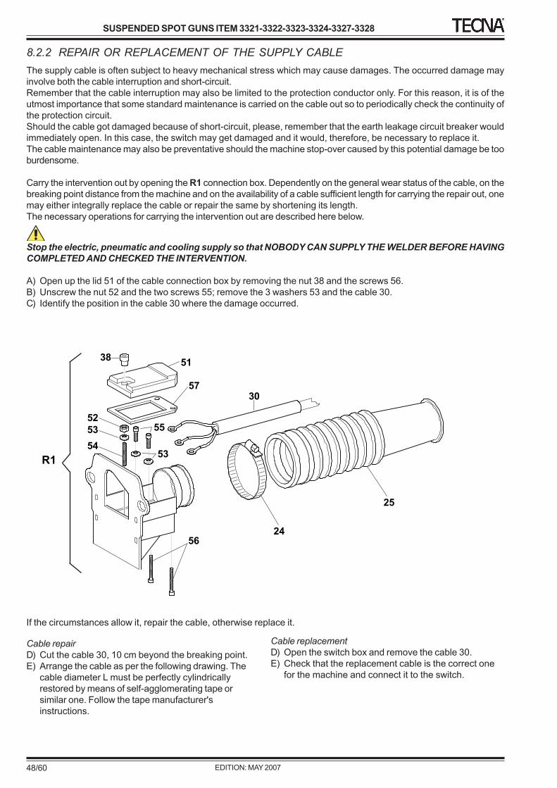
3 TRANSPORT AND HANDLING ......................................................................................................................143.0 GENERAL INFORMATION .............................................................................................................................. 143.1 PACKING ........................................................................................................................................................ 143.2 TRASPORT AND HANDLING OF THE PACKED WELDER ............................................................................. 143.3 STORAGE OF THE WELDER BOTH PACKED AND UNPACKED................................................................... 143.4 UNPACKING ................................................................................................................................................... 153.5 HANDLING OF THE UNPACKED WELDER .................................................................................................... 15
4 INSTALLATION ..............................................................................................................................................164.0 GENERAL WARNINGS .................................................................................................................................. 164.1 REQUIRED ENVIRONMENT CONDITIONS ..................................................................................................... 164.2 LOCATION OF THE WELDER ........................................................................................................................ 164.3 ACCOMPLISHMENT OF THE ASSEMBLY ..................................................................................................... 174.4 CONNECTION TO THE ELECTRIC SUPPLY ................................................................................................... 18
5 WELDER SET UP ...........................................................................................................................................205.0 GENERAL NOTICE ......................................................................................................................................... 205.1 DESCRIPTION OF THE WELDING CONTROL UNIT ....................................................................................... 205.1.1 BUILT-IN CONTROL UNIT TE300 ..................................................................................................................... 205.1.2 BUILT-IN CONTROL UNIT TE450 ..................................................................................................................... 215.2 ELECTRIC GENERAL SWITCH (Emergency Interruption) ............................................................................... 225.3 SAFETY RULES ............................................................................................................................................. 225.4 MACHINE FUNCTIONING ...............................................................................................................................235.5 RESIDUAL RISKS .......................................................................................................................................... 25
6 MACHINE USE ...............................................................................................................................................266.0 GENERAL INFORMATION .............................................................................................................................. 266.1 CALCULATION OF THE MAXIMUM WELDING RATING .................................................................................. 266.2 TROUBLESHOOTING .................................................................................................................................... 276.3 REMEDIES FOR WELDS IMPERFECTIONS .................................................................................................. 29
7 INSTRUCTIONS FOR THE ADJUSTMENTS ..................................................................................................307.0 GENERAL INFORMATION .............................................................................................................................. 307.1 STANDARD ACCESSORIES........................................................................................................................... 307.2 MECHANICAL SET UP ................................................................................................................................... 307.2.1 ARMS SELECTION AND REPLACEMENT ..................................................................................................... 307.2.2 SUSPENSION ADJUSTMENT ......................................................................................................................... 347.2.3 ARMS ADJUSTMENT ..................................................................................................................................... 367.2.4 ELECTRODES ADJUSTMENT ........................................................................................................................ 387.2.5 WORKING STROKE ADJUSTMENT ............................................................................................................... 407.2.6 DOUBLE STROKE USE ................................................................................................................................. 427.3 ELECTRODE FORCE ADJUSTMENT ............................................................................................................. 437.4 WORKING PROGRAM ADJUSTMENT............................................................................................................ 45
8 MAINTENANCE ..............................................................................................................................................468.0 GENERAL INFORMATION .............................................................................................................................. 468.1 ORDINARY MAINTENANCE ........................................................................................................................... 468.2 EXTRAORDINARY MAINTENANCE ................................................................................................................ 478.2.1 LOWERING OF THE WELDING UNIT PERFORMANCES .............................................................................. 478.2.2 REPAIR OR REPLACEMENT OF THE SUPPLY CABLE ................................................................................ 48
9 SUPPLEMENTARY INSTRUCTIONS ..............................................................................................................509.0 GENERAL INFORMATION .............................................................................................................................. 509.1 WASTE DISPOSAL ........................................................................................................................................ 509.2 OFF DUTY EQUIPMENT AND DISMANTLING ................................................................................................ 509.3 EMERGENCY CONDITIONS INSTRUCTIONS................................................................................................. 50
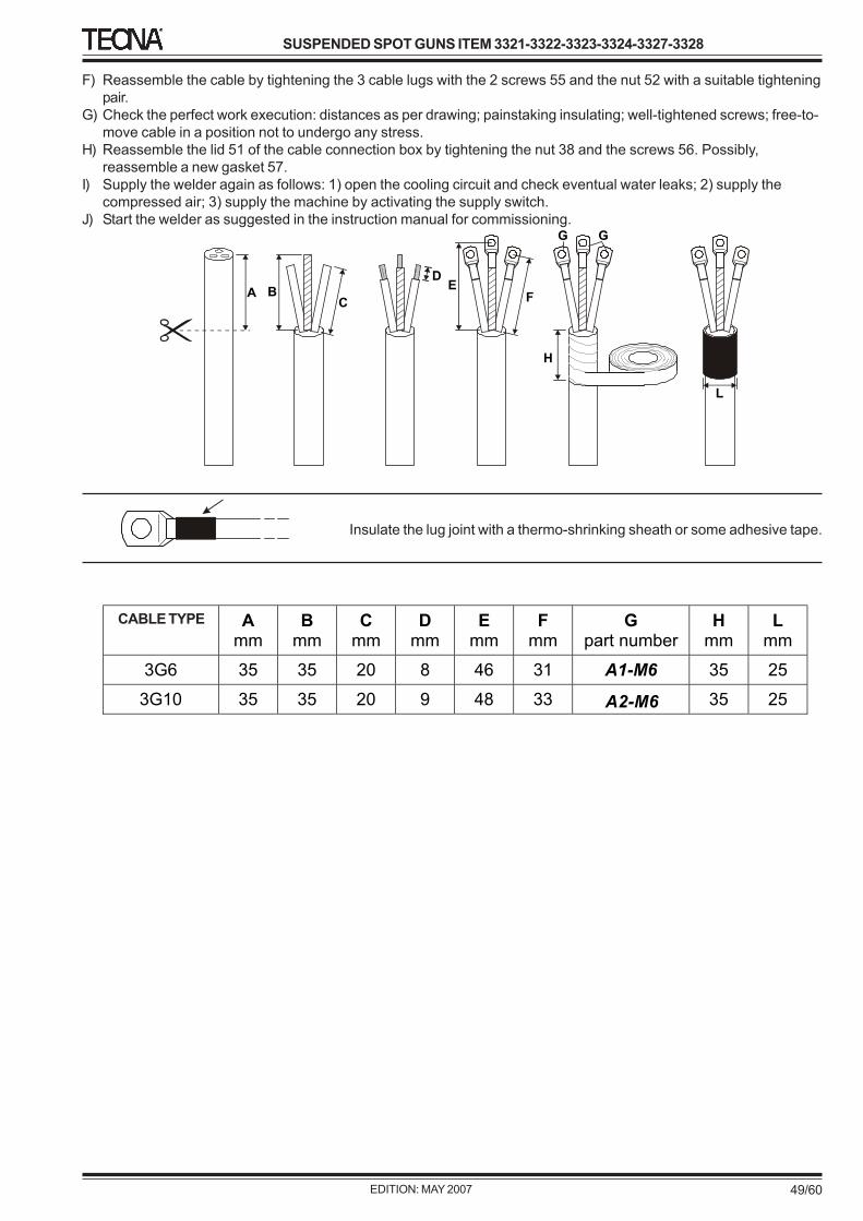
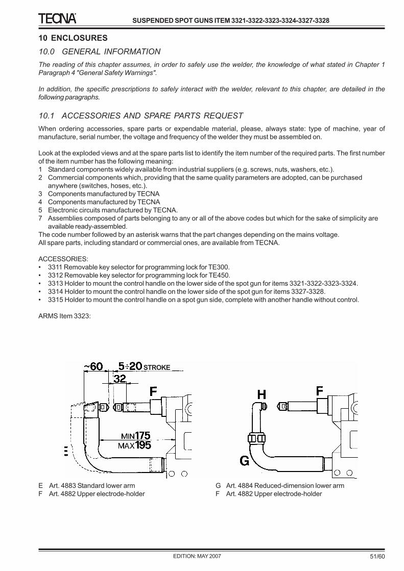
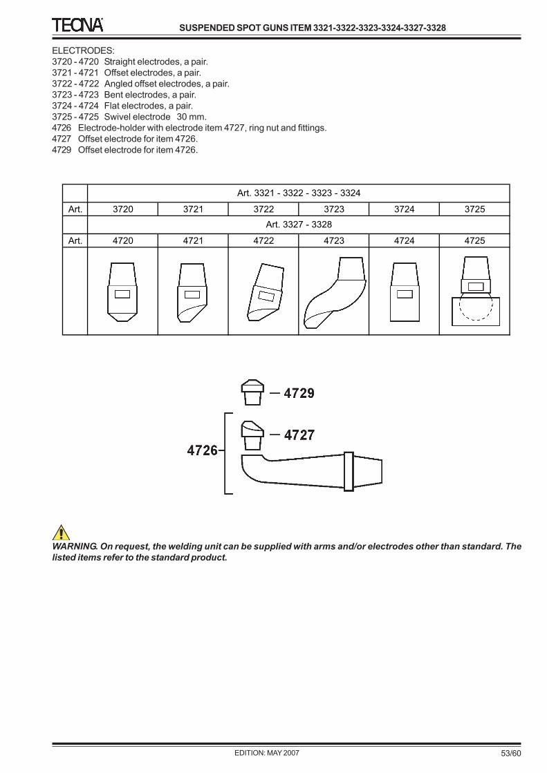
10 ENCLOSURES ...............................................................................................................................................5110.0 GENERAL INFORMATION .............................................................................................................................. 5110.1 ACCESSORIES AND SPARE PARTS REQUEST ........................................................................................... 5110.2 WELDING TABLES ......................................................................................................................................... 5410.3 TE300 PRODUCTION FORM FACSIMILE ....................................................................................................... 5610.4 TE450 PRODUCTION FORM FACSIMILE ....................................................................................................... 57
0 INTRODUCTIONCAREFULLY READ THIS INSTRUCTION MANUALBEFORE INSTALLING AND OPERATING THE WELDER.
0.1 PURPOSE OF THE INSTRUCTIONMANUAL
This instruction manual is part of the welder and is aimedat providing all the necessary information in order to:
• provide the operators with the proper informationconcerning safety issues;
• handle the welder, both packed and unpacked, undersafety conditions;
• properly install the welder;• deeply be acquainted with the working of the welder
and its limits;• use properly the welder under safety conditions;• change type of production and perform maintenance,
adequately and safely;• dismantle the welder under safe conditions and in
compliance with the provisions in force about theworkers and environment care.
The personnel responsible of each department, in whichthe welder will be installed, are obliged, according tothe laws in force, to carefully read the content of thisdocument and make it available for reading to thepersonnel who use and maintain the welder, for the partsrelevant for them.The time spent in this activity will be widely savedthanks to a proper working of the welder and its useunder safety conditions.
This document is based on the supposition that the safetyand sanitary rules in force are applied in the place wherethe welder will be installed.
The instructions, drawings and the content of this manualhave a technical nature and their property is strictly reservedto the manufacturer and cannot be reproduced in any way,neither fully nor partially.
Besides, the customer undertakes the responsibility tocheck that, in case this document is modified by themanufacturer, only the updated versions of this manual arepresent where the welder is used.
This welder has been designed for resistance welding ofboth ferrous and non ferrous (aluminium, brass) materials.The welder must not be used for other applications; i.e.pieces heating, mechanical working carried out by usingthe electrodes force. The welder has been designed to beused by an operator by using the foreseen control devices.All modifications, even slight ones, are forbidden becausethey should invalidate the welder CE certification.
The welders described in this manual have beendesigned to be used only for professional purposes inindustrial environments. They must not be installed onpublic lines at low voltage supplying domesticpremises. This can cause electromagnetic interferences.
TECNA S.p.A. is not responsible for any damage to bothpeople, animals, things and to the welder itself caused bya wrong use, or the lack or the superficial observance of thesafety warnings stated in this manual, nor it is responsiblefor damages coming from even slight tampering or from theuse of not-suitable spare parts, or of spare parts other thanthe original ones.
0.2 KEEPING OF THE INSTRUCTIONMANUAL
The instruction manual must be kept with care and mustalways follow the welder in all the changes of property thatit could have during its life.
The good keeping must be enhanced by a careful handling,with clean hands and having care not to put it on dirtysurfaces.
It is forbidden to take off, tear or to arbitrarily change partsof this instruction manual.
The manual must be stored in a place safe from humidityand heat and close to its relevant welder.
0.3 HOW TO UPDATE THE INSTRUCTIONMANUAL
In case of any modification on the welder installed at thecustomer premises, that have been agreed upon by themanufacturer and that require to change the InstructionManual, the manufacturer should send the revised InstructionManual.
The user is responsible for changing the old manual withthe new one.
The welding machines of the manufacturer are covered bywarranty, as per general sales conditions. If, within thevalidity of the warranty, defective workings of the welder orfaults, which are included in the warranty clauses, aredetected, the manufacturer will take care of repair orreplacement of faulty parts, after his technical evaluationon the welder.
It is reminded that even slight modifications made by theuser, without written authorization by the manufacturer,invalidate the warranty and discharge the manufacturer byany responsibility for damages caused by a defectiveproduct.
This is valid especially in case above modifications are madeon safety devices, invalidating their efficiency.
The same prescriptions are valid when using nonoriginal spare parts or spare parts different from theones explicitly informed by the manufacturer.
For all the above reasons, we suggest to our customersto call our Technical Service for any problem.
1.4 GENERAL SAFETY RULES
Before using the welder it is necessary to carefully readthe instructions in this manual and carefully follow itsprescriptions.
The manufacturer has designed this welder to beINTRINSICALLY SAFE, as much as possible. The welderhas been equipped with all the protections and safetydevices which have been deemed necessary, and finally, itis provided with information enough for its safe and correctuse.
To this purpose in each chapter, when necessary, for theoperator-welder interaction the following information havebeen provided:
• Minimum operator skills required• Number of operators required• Status of the welder• Remaining dangers• Necessary or suggested protection devices• Avoidance of human errors• Prohibitions/obligations referred to mistaken actions
The user can appropriately add information to the onesprovided by the manufacturer for example additional workinginstructions, which of course must not be in contrast towhat is stated in this manual, in order to help safe use ofthe welder.
For example, particular attention must be paid to the clothesworn by anyone working with the welder:
- avoid wearing clothes with holds which could becaught into the welder;
- avoid using ties or flying clothes;- avoid wearing large rings or armlets which could get
the hands caught by the welder
When necessary, this manual will specify furtherrecommendations for the user about the preventivemeasures, personal protection devices, information aimedto prevent human errors and prohibitions for wrongbehaviours which can be reasonably foreseen.
In any case it is necessary to carefully follow the indicationshere below:
• It is absolutely forbidden to void the safety devicesinstalled in the machine;
• The operations at a reduced safety rate must beperformed by carefully following the instructionsprovided in the relevant descriptions;
• After an operation at a reduced safety rate the normalstatus of the welder must be restored at the soonest;
• The cleaning operations must be performed withelectrical and pneumatic devices switched off;
• Do not modify parts of the welder for any reason: incase of malfunctioning, due to this reason, themanufacturer is not responsible. It is advisable to askfor any modifications directly to the manufacturer.
• Clean the covers of the welder, the panels and thecontrols with dry soft clothes or slightly wet with a softcleaning solution; do not use solvents, like alcohol orgasoline, resulting in a possible damage of the welder;
• Place the welder as established upon order; if not, themanufacturer is not responsible for any inconvenience.
1.5 GLOSSARY AND SYMBOLS ON THEWELDER AND IN THE MANUAL
This paragraph lists the words which are not commonlyused or which are used with a meaning different from thecommon one.
This paragraph also explains the short forms used in themanual and the meaning of the symbols used to show theoperator skill degree and the status of the welder: their useenables to quickly and easily provide the informationnecessary to the proper use of the welder under safeconditions.
GLOSSARY:DANGEROUS AREA: An area inside and/or close to thewelder in which the presence of an exposed person is riskyfor the safety and the health of the same person (EnclosureI, 1.1.1 Directive 98/37/CE);
EXPOSED PERSON: Any person who is fully or partially ina dangerous area (Enclosure I, 1.1.1 Directive 98/37/CE);
OPERATOR: The person in charge for installing, working,adjusting, maintaining, cleaning, repairing and transportingthe welder (Enclosure I, 1.1.1 Directive 98/37/CE);
INTERACTION MAN-MACHINE: Any situation in which anoperator acts with the welder in any of the operation phasesand in any period of the life of the welder;
OPERATOR QUALIFICATION: Minimum skills level anoperator must have to carry the described operation out;
OPERATORS NUMBERS: Suitable number of operators forcarrying the described operation out in good conditions.This is the outcome of a careful analysis of themanufacturer’s: should the operation be carried out by adifferent number of operators, this could either prevent fromobtaining the expected result or endanger the involvedpersonnel’s safety;
RESIDUAL DANGER: Danger which was not possible toremove or sufficiently reduce by means of the engineering.The protections are not (or are not totally) effective againstthis danger. The instruction manual informs about itsexistence and provides the instructions and the advice forovercoming the same (see, respectively, 5.5 and 5.5.1 ofthe European Regulations EN 292/1 e EN 292/2);
SAFETY COMPONENT: We mean a component used forensuring a safety function. Should it be either damaged orwork improperly, it would compromise either the safety and/or the health of the exposed people (for instance: liftingtool, fixed, mobile, adjustable protector, etc., electric,electronic, optical pneumatic, hydraulic device interlockinga protector, etc.);
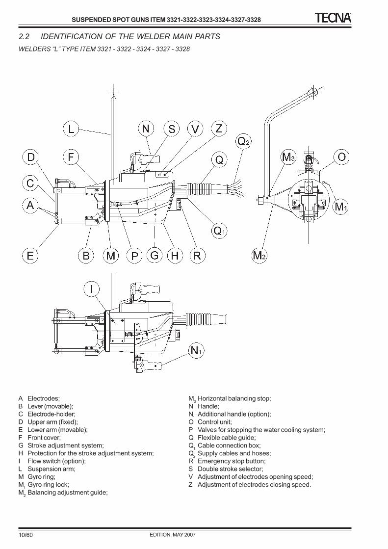
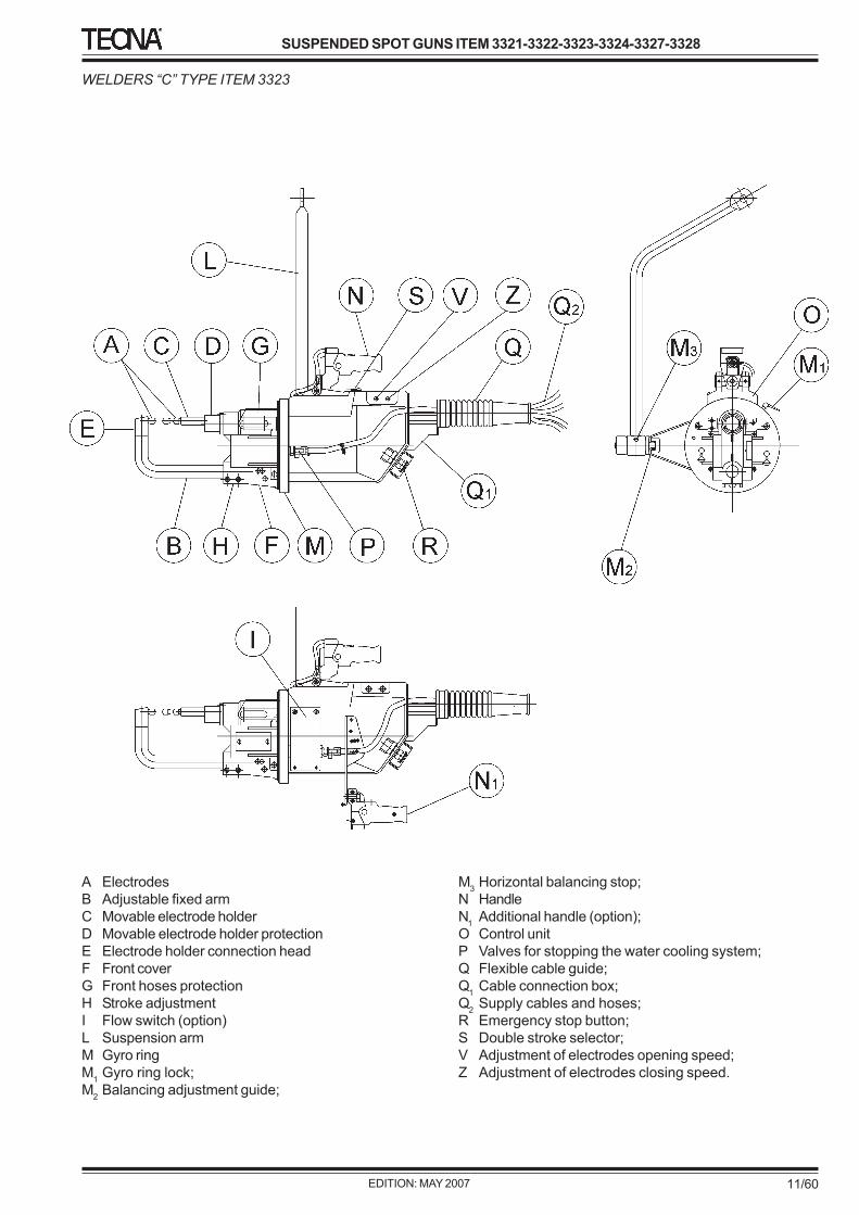
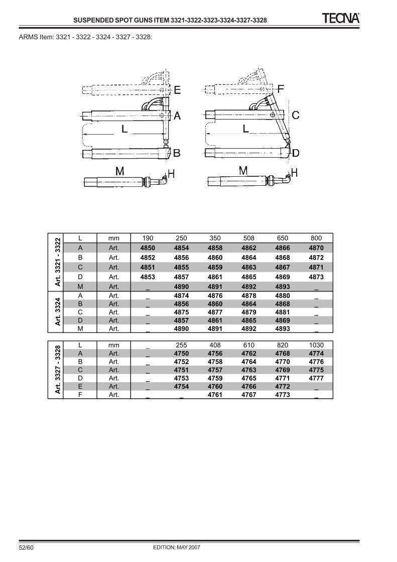
2.2 IDENTIFICATION OF THE WELDER MAIN PARTSWELDERS “L” TYPE ITEM 3321 - 3322 - 3324 - 3327 - 3328
A Electrodes;B Lever (movable);C Electrode-holder;D Upper arm (fixed);E Lower arm (movable);F Front cover;G Stroke adjustment system;H Protection for the stroke adjustment system;I Flow switch (option);L Suspension arm;M Gyro ring;M1 Gyro ring lock;M2 Balancing adjustment guide;
M3 Horizontal balancing stop;N Handle;N1 Additional handle (option);O Control unit;P Valves for stopping the water cooling system;Q Flexible cable guide;Q1 Cable connection box;Q2 Supply cables and hoses;R Emergency stop button;S Double stroke selector;V Adjustment of electrodes opening speed;Z Adjustment of electrodes closing speed.
2.4 FORESEEN USEAIR OPERATED PRODUCTION SPOT GUNS WITH BUILT-IN ELECTRONIC TIMER
ANY USE DIFFERENT FROM AND NOT FORSEEN INTHIS MANUAL MAKES TECNA S.p.A. NOTRESPONSIBLE FOR ANY RISKS SHOULD TAKE PLACE.
In any case, the use of materials different from the onesagreed upon the purchase EXCLUDES TECNA S.p.A.FROM ANY RESPONSIBILITY FOR DAMAGES TO THEWELDER, THINGS OR PEOPLE.
The electrical system is not foreseen to be used in antiexplosion environments and for flammable products.
3 TRANSPORT AND HANDLING3.0 GENERAL INFORMATIONThe reading of this chapter assumes, in order to safely usethe welder, the knowledge of what stated in Chapter 1Paragraph 4 “General Safety Warnings”.
In addition, the specific prescriptions to safely interact withthe welder, relevant to this chapter, are detailed in thefollowing paragraphs.
3.1 PACKINGTHE WELDER CAN BE PACKED ON PALLET
Then it is covered by a poly-ethylene film to get a higherprotection.
Protruding parts are usually disassembled and packedseparately.
Upon receipt of the welder, it is necessary to check (visually,with the lorry driver) the complete integrity of the packingand inform any damage to a responsible.
Any damage on the packing should raise doubts about theintegrity of the welder.
PACKING FEATURES
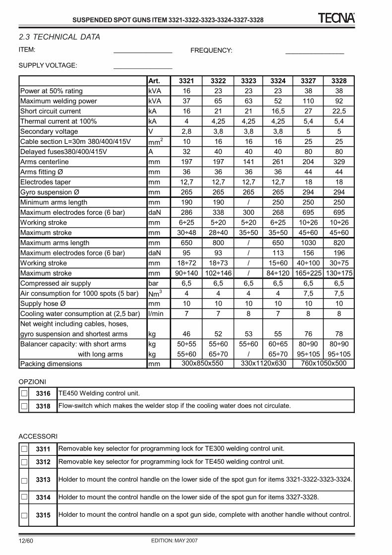
PACKING DIMENSIONS: See technical data table
Values subject to change according to the configuration ofthe welder.
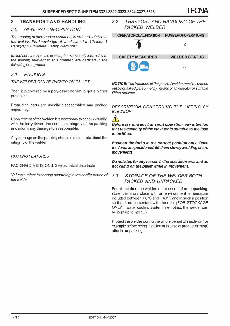
3.2 TRASPORT AND HANDLING OF THEPACKED WELDER
OPERATOR QUALIFICATION NUMBER OF OPERATORS
2
SAFETY MEASURES WELDER STATUS
- -
NOTICE: The transport of the packed welder must be carriedout by qualified personnel by means of an elevator or suitablelifting devices.
DESCRIPTION CONCERNING THE LIFTING BYELEVATOR
Before starting any transport operation, pay attentionthat the capacity of the elevator is suitable to the loadto be lifted.
Position the forks in the correct position only. Oncethe forks are positioned, lift them slowly avoiding sharpmovements.
Do not stop for any reason in the operation area and donot climb on the pallet while in movement.
3.3 STORAGE OF THE WELDER BOTHPACKED AND UNPACKED
For all the time the welder in not used before unpacking,store it in a dry place with an environment temperatureincluded between + 0°C and + 40°C and in such a positionso that it not in contact with the rain. (FOR STOCKAGEONLY, if water cooling system is emptied, the welder canbe kept up to -20 °C)
Protect the welder during the whole period of inactivity (forexample before being installed or in case of production stop)after its unpacking.
3.4 UNPACKINGUNPACKING OF PALLET WITH PROTECTIVE FILM
Transport the welder close to the place of installation, then:
- Take off the plastic protection which covers the welderpaying attention not to damage it.
- (Visually) check the external integrity of the welder.
- Check that the welder is complete with all thestandard accessories; should some parts be missing,immediately inform the manufacturer.
- All the material forming the package must bescrapped according to the present environmentalsafety regulations.
3.5 HANDLING OF THE UNPACKEDWELDER
OPERATOR QUALIFICATION NUMBER OF OPERATORS
2
SAFETY MEASURES WELDER STATUS
- -
NOTICE: The transport of the unpacked welder should beperformed by skilled personnel by means of either a forkelevator or strip /chain lifting conveyors.
Pay attention, before transporting the welder, that thecapacity of the elevator is suitable with the load to belifted.
The welder must be handled only by means of its ownsuspension system.
Handling of the welder without suspension arm
Handling of welder with suspension arm
Until the suspension arm is not mounted in the welder, usethe proper hole located on the suspension fixing plate. Oncethe suspension arm has been installed, use the same forhandling the welder.Take into consideration the welder weight as shown in theparagraph “TECHNICAL FEATURES”.
4 INSTALLATION4.0 GENERAL WARNINGSThe reading of this chapter, to the purpose of the safe useof the welder, assumes the acknowledgement of theChapter 1, Paragraph 2 “General Safety Warnings”.
These paragraphs are intended for specialized personnelresponsible for the handling and installation of the welders.
Moreover, the specific prescriptions for safely interact withthe welder, relating to this chapter, are detailed in the followingparagraphs.
4.1 REQUIRED ENVIRONMENTCONDITIONS
The machine is intended to work under the environmentalconditions specified in the following points, if not otherwisestate in the order form:
TEMPERATUREThe welder can work at a room temperature includedbetween 0°C and + 40°C. (FOR STOCKAGE ONLY, if thewater is removed from the water cooling circuit, the weldercan be stored up to -20 °C)
HUMIDITYThe welder can work at a humidity varying from 15% to95%.
ALTITUDEThe welder can work at a max. 1000 m altitude without alowering of performance.
ILLUMINATIONThe welder has been designed taking into account theprescriptions to make the operator work easily. The lightingsystem of the plant is also important for the people safety.
EXPLOSIVE AND/OR FLAMMABLE ATMOSPHEREThe standard version of the welder is not designed to workin either explosive atmosphere or flammable ones.
4.2 LOCATION OF THE WELDERThe welder should be installed in a position having thefollowing features:
• Indoors, the welder is not designed for workingoutdoors.
• In a well ventilated area, free from dust, steam andacid exhalations.
• The working place must be free from inflammablematerials because the working process can producespatters of melted metal.
• Around the welder there must be enough room tocarry out both working and maintenance in acomfortable manner and without any risk.
• In a place with a suitable lighting system incomparison with the work to be carried out.
• The place of installation must be necessarily flat andthe ground must be without unevenness which can bedangerous when working.
If the welder is used to carry out welding processes whichcan cause smoke exhalations, a proper aspirator must beinstalled.
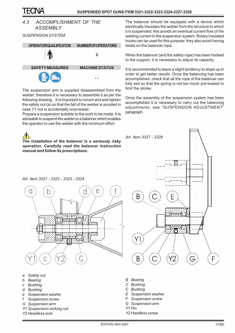
The suspension arm is supplied disassembled from thewelder; therefore it is necessary to assemble it as per thefollowing drawing. It is important to mount and well tightenthe safety nut (a) so that the fall of the welder is avoided incase Y1 nut is accidentally unscrewed.Prepare a suspension suitable to the work to be made. It isadvisable to suspend the welder to a balancer which enablesthe operator to use the welder with the minimum effort.
The installation of the balancer is a seriously riskyoperation. Carefully read the balancer instructionmanual and follow its prescriptions.
The balancer should be equipped with a device whichelectrically insulates the welder from the structure to whichit is suspended; this avoids an eventual current flow of thewelding current to the suspension system. Rotary insulatedhooks can be used for this purpose: they also avoid havingtwists on the balancer rope.
When the balancer (and the safety rope) has been hookedto the support, it is necessary to adjust its capacity.
It is recommended to leave a slight tendency to slope up inorder to get better results. Once the balancing has beenaccomplished, check that all the rope of the balancer canfully exit so that the spring is not too much pre-loaded tolimit the stroke.
Once the assembly of the suspension system has beenaccomplished it is necessary to carry out the balancingadjustments, see “SUSPENSION ADJUSTMENT”paragraph.
OPERATOR QUALIFICATION NUMBER OF OPERATORS SAFETY MEASURES MACHINE STATUS
1 - -
Before performing any connection to the system of the plant check the perfect cleaning of the hoses: they shouldbe free from any external dust, remaining from the unpacking or from storage in an inconvenient place.
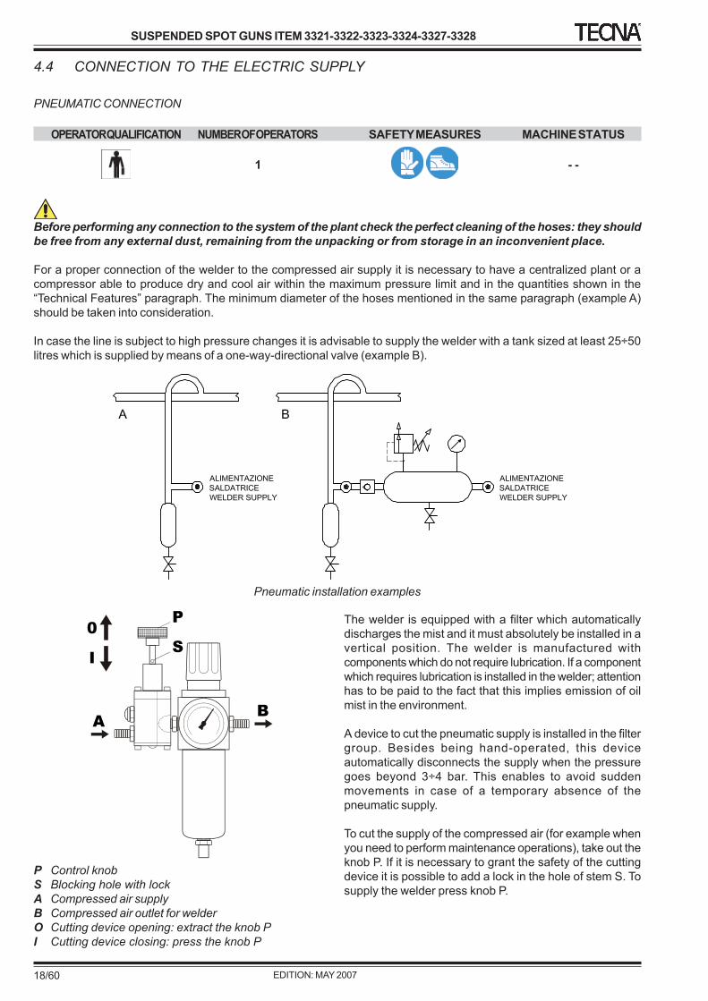
For a proper connection of the welder to the compressed air supply it is necessary to have a centralized plant or acompressor able to produce dry and cool air within the maximum pressure limit and in the quantities shown in the“Technical Features” paragraph. The minimum diameter of the hoses mentioned in the same paragraph (example A)should be taken into consideration.
In case the line is subject to high pressure changes it is advisable to supply the welder with a tank sized at least 25÷50litres which is supplied by means of a one-way-directional valve (example B).
The welder is equipped with a filter which automaticallydischarges the mist and it must absolutely be installed in avertical position. The welder is manufactured withcomponents which do not require lubrication. If a componentwhich requires lubrication is installed in the welder; attentionhas to be paid to the fact that this implies emission of oilmist in the environment.
A device to cut the pneumatic supply is installed in the filtergroup. Besides being hand-operated, this deviceautomatically disconnects the supply when the pressuregoes beyond 3÷4 bar. This enables to avoid suddenmovements in case of a temporary absence of thepneumatic supply.
To cut the supply of the compressed air (for example whenyou need to perform maintenance operations), take out theknob P. If it is necessary to grant the safety of the cuttingdevice it is possible to add a lock in the hole of stem S. Tosupply the welder press knob P.
P Control knobS Blocking hole with lockA Compressed air supplyB Compressed air outlet for welderO Cutting device opening: extract the knob PI Cutting device closing: press the knob P
Before performing the connection to the plant system,check the perfect cleaning of the welder hoses: theyshould be free from any external accidental remain ofthe unpacking, or from storage in an inconvenientplace.
For a proper cooling of the welder it is necessary to useclean water at a maximum temperature of 30 °C in thequantity shown in the paragraph “Technical Features”.
When performing the connection, pay attention that thehoses are free from dirt or from remains of package. Thenconnect the supply to the inlet and the discharge to theoutlet; this is to allow the water which is still cold to reachthe parts of the welder that are most subject to heating.
It is possible to have different water cooling systems: bymeans of a closed circuit, of a water-air heat exchangerand by a water cooler. If the circuit is closed or with a watercooler and the air in the working environment has a highpercentage of humidity, it is advisable to avoid water at alow temperature – lower than 20° C as this could causemoist inside the welder.
If water is hard or calcareous it is necessary to install awater softener at the inlet hose of the water-cooling circuitof the welder; this is to avoid that deposits obstruct or redu-ce the water cooling hoses causing damages to the welder.In case of water cooling by closed circuit, this softenershould be positioned before the supply of the bath whichcontains the water used for cooling.
We recommend using water with a maximum hard water of10 °fH (French degrees). 1 °fH (French degree) correspondsto 0.56 °dH (German degree), and to 0.7 °eH (Englishdegree).
Check that the water being used is clean. Suspendedparticles in the cooling liquid might sediment in the machinereducing or cancelling the cooling capability and causingserious damages. For this reason it is always advisable toassemble a proper filter on the machine supply.Once the installation has been accomplished, it isnecessary to check that the water flow in the weldercorresponds to the quantity shown in “Technical Features”paragraph.
ELECTRICAL INSTALLATION
OPERATOR QUALIFICATION NUMBER OF OPERATORS
1
SAFETY MEASURES WELDER STATUS
- -
The welders in this manual have been designedexclusively for professional use in an industrialenvironment. They must not be installed in low voltagepublic lines which supply domestic premises. This cancause electromagnetic interferences.The electrical installation of the welder to the mainssupply is carried out by the customer at his ownexclusive risk and responsibility, by using specializedpersonnel who should carefully follow the indicationsof this instruction manual.
Before connecting the welder to the mains supply check ifthe voltage shown on the features plate corresponds to theone of your mains supply.
When realising the supply line of the welder consult the“Technical features” table to determine the cables sectionto be used. These values are the minimum advised. However,they must be checked taking into consideration theinstallation conditions, the typology of the materials beingused, and the laws in force in the installation place.
The welder is equipped with an earth leakage circuit breakerlocated at the end of the supply cable. Besides breakingthe electric supply, this device has safety functions thereforeit must not be absolutely taken off. The switch must beinstalled close to the working place so that the operatorcan easily reach it. If the breaking capacity offered by theearth leakage circuit breaker is not adequate to the mainssystem, or if it is required by the laws in force, install delayedfuses in the size shown in the “Technical Features”paragraph granting an adequate breaking capacity.
The paragraph TECHNICAL DATA 2.3 reports the featuresof the supplied switch.The connection of the welder to the protection conductor(earth conductor) is compulsory. Check that the conductorof the protection system is efficient and complies with thelaws in force.
5 WELDER SET UP5.0 GENERAL NOTICEThe reading of this chapter assumes, to the purpose of a safe use of the welder, the acknowledgement of what is statedin Chapter 1 Paragraph 4 “General safety warnings”.
Besides, the specific prescriptions to safely operate the welder, relating to this chapter, are detailed in the followingparagraphs.
5.1 DESCRIPTION OF THE WELDING CONTROL UNITThe welder can be equipped with different types of control units, either external to or built-in the welder. The followingparagraphs describe the features of the different available types.
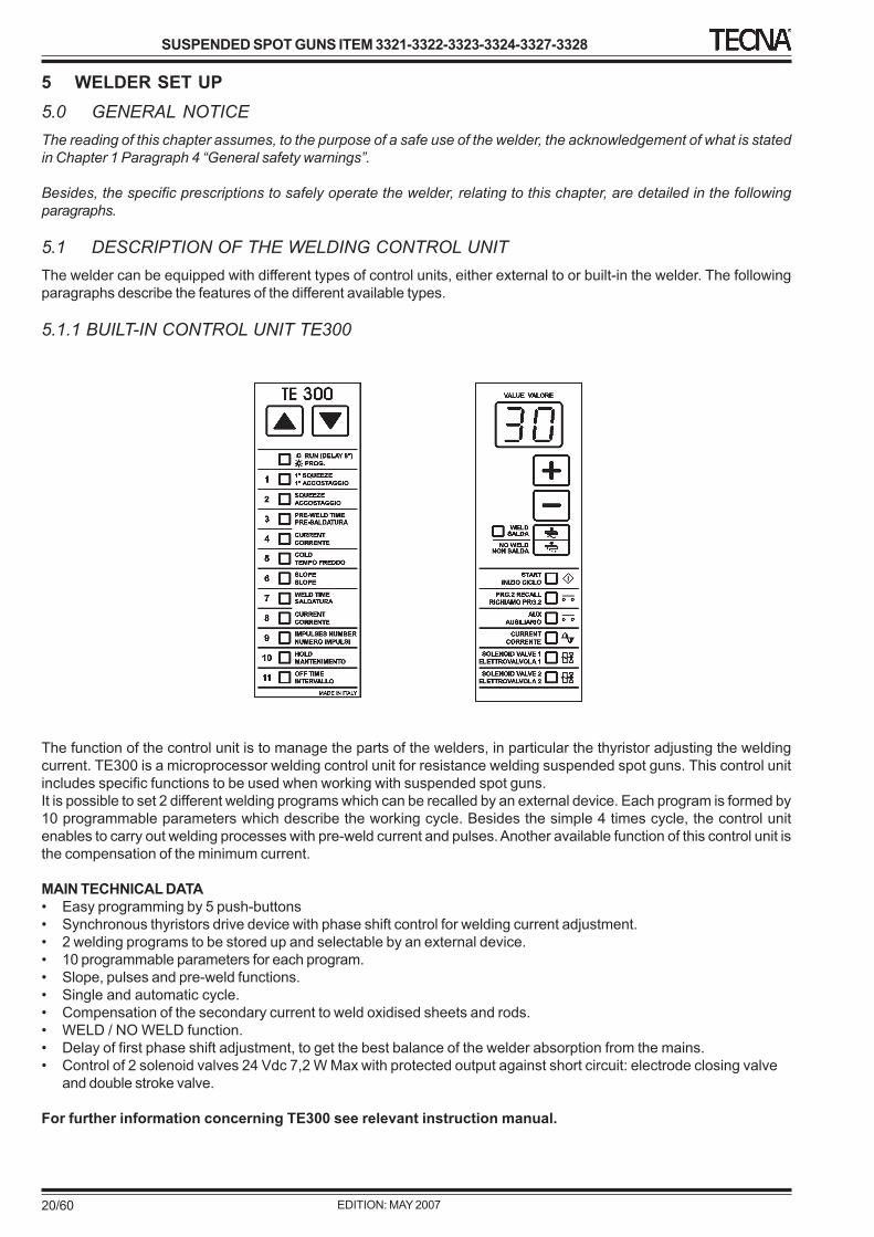
5.1.1 BUILT-IN CONTROL UNIT TE300
The function of the control unit is to manage the parts of the welders, in particular the thyristor adjusting the weldingcurrent. TE300 is a microprocessor welding control unit for resistance welding suspended spot guns. This control unitincludes specific functions to be used when working with suspended spot guns.It is possible to set 2 different welding programs which can be recalled by an external device. Each program is formed by10 programmable parameters which describe the working cycle. Besides the simple 4 times cycle, the control unitenables to carry out welding processes with pre-weld current and pulses. Another available function of this control unit isthe compensation of the minimum current.
MAIN TECHNICAL DATA• Easy programming by 5 push-buttons• Synchronous thyristors drive device with phase shift control for welding current adjustment.• 2 welding programs to be stored up and selectable by an external device.• 10 programmable parameters for each program.• Slope, pulses and pre-weld functions.• Single and automatic cycle.• Compensation of the secondary current to weld oxidised sheets and rods.• WELD / NO WELD function.• Delay of first phase shift adjustment, to get the best balance of the welder absorption from the mains.• Control of 2 solenoid valves 24 Vdc 7,2 W Max with protected output against short circuit: electrode closing valve
and double stroke valve.
For further information concerning TE300 see relevant instruction manual.
The welding control unit is used to control the welder parts and, in particular, the thyristor adjusting the welding current.TE450 is a microprocessor welding control unit for resistance welding suspended spot guns. This control unit includesspecific functions to be used when working with suspended spot guns. The handle is not a standard component of thewelding control unit; it is possible to install different handles so to set the machine according to different working needs.It is possible to store up to 63 different welding programs; it is possible to directly recall 2 programs by means of anexternal selector usually installed on the handle. Each program is formed by 18 adjustable parameters describing theworking cycle. Besides the simple 4 times cycle, the control unit enables to carry out welding processes with pre-weld,post-weld current, slope and pulses. TE450 can work in constant current mode; it displays the welding current and checkthe current according to set limits.
MAIN TECHNICAL DATA• Easy programming by means of 5 push-buttons and LCD alphanumeric display.• Synchronous thyristors drive with phase shift control for welding current adjustment.• 63 welding programs to be stored up, 2 of them can be recalled from an external device.• 18 programmable parameters for each program.• Slope, pulses, pre-weld and post-weld functions.• Welding times adjustment in half-periods.• Display of both welding current in kA and relevant conduction angle.• Double working mode: standard and constant current.• Either welding current or conduction angle limits.• Stepper function to balance the electrodes wear with adjustable curve.• Welds counter.• Compensation of secondary current to weld oxidised sheets and rods.• Single and automatic cycle. WELD / NO WELD function.• Delay of first phase shift adjustment to get the best balance of the machine absorption from the mains.• Control of 2 solenoid valves 24 Vdc 7,2 W Max with protected output against short circuit: electrode closing valve
and double stroke valve.
For further information concerning TE450 see the relevant instruction manual.
5.2 ELECTRIC GENERAL SWITCH(Emergency Interruption)
Following to a dynamic-type action and while being supplied,the machine is designed for being stopped in EMERGENCYINTERRUPTION conditions by the operator by acting onthe machine’s general switch so to remove an electric danger.
The placing in service of the welder after an emergencycondition must be carried out only by qualified personneltrained to accomplish all the machine necessary tests.If the machine was stopped during the welding process, itis necessary to execute the following procedure beforerestart the production in order to restore the normaltransformer magnetisation condition: carry out some weldswith an insulator placed between the electrodes withdifferent current adjustments, first low ones, thenprogressively higher; remove the insulator betweenelectrodes and execute some welds with a low currentadjustment; at this point the procedure ends and the normalfunctioning conditions are restored.
In case of any water leakage which could enter the welder,immediately disconnect the electric supply.
In case of fire do not use water but proper fire extinguishers.
5.3 SAFETY RULES
OPERATOR QUALIFICATION NUMBER OF OPERATORS
1
SAFETY MEASURES WELDER STATUS
OFF
For a safe welder employ, the installation must be carriedout by specialised personnel following all the instructionsstated on the “INSTALLATION” chapter.
The welder maintenance must be carefully carried out byfollowing all the safety instructions stated on the“MAINTENANCE” chapter. In particular, notice that theelectrodes maintenance must be carried out according toeither one of the following conditions:• with the welder switched off.• with the emergency button pressed down.
The welder should be operated by trained personnelonly; in any case, users operating the welder must beaware of the possible risks and must have both readand understood this manual.
Only authorised personnel can carry out the welderadjustment. The welder adjustments affect the operativesafety so much so that they must be carried out by qualifiedpersonnel only.
Carefully follow the instructions stated on the “WORKINGPROCESS” chapter.
It is forbidden to have more people working on thewelder at the same time. No admittance allowed tothe working area to people other than the operator.
In case of water entering the welder, immediately stop theelectrical supply.
When operating heavy working, high thickness and pieceswith a difficult coupling, wear safety shoes and aprons, anduse protection screens to protect the operator from possiblespatters of melted materials.
The safety shoes must be worn each time the pieces to bewelded, because of their shape or weight, bear risks requiringthem.
Keep the welder’s nearby working area free from flammablematerials. In case the material to be welded produces eithersmokes or exhalations, install a proper aspirator.
The noise produced by the welder depends mainly on theadjustments. To reduce the noise:Adjust the working stroke to the minimum value allowingcarrying out the operation.• Adjust the working stroke to the minimum value
allowing carrying the operation out.• Work having the double stroke activated.• Adjust both the electrodes opening and closing
speeds to low values.• Periodically check the silencers.Should the noise produced by the welder during the workingphases exceed the safety threshold, wear the properprotection headphones.
In addition to the information stated on this chapter, alwaysoperate in accordance with all the relevant laws in force.
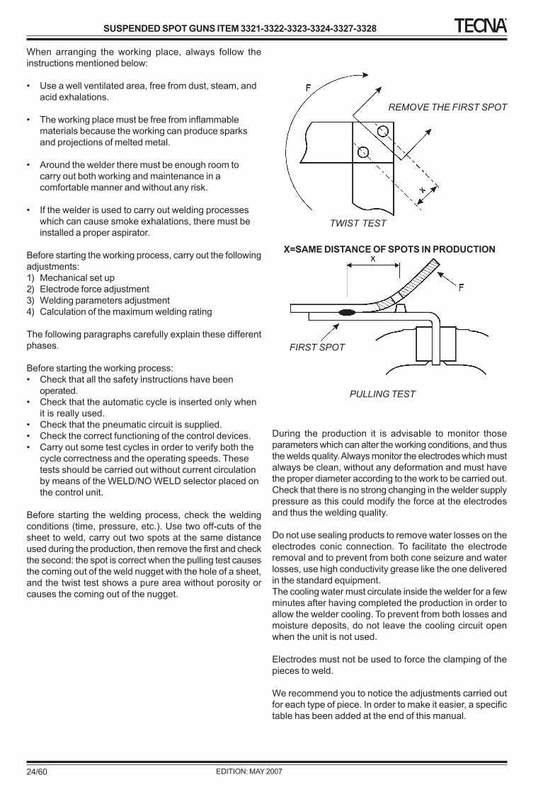
5.4 MACHINE FUNCTIONING
OPERATOR QUALIFICATION NUMBER OF OPERATORS
OPERATOR 1
SAFETY MEASURES WELDER STATUS
ON
The welder was designed for being used by an operatorplaced as represented in the pictured examples:
When arranging the working place, always follow theinstructions mentioned below:
• Use a well ventilated area, free from dust, steam, andacid exhalations.
• The working place must be free from inflammablematerials because the working can produce sparksand projections of melted metal.
• Around the welder there must be enough room tocarry out both working and maintenance in acomfortable manner and without any risk.
• If the welder is used to carry out welding processeswhich can cause smoke exhalations, there must beinstalled a proper aspirator.
Before starting the working process, carry out the followingadjustments:1) Mechanical set up2) Electrode force adjustment3) Welding parameters adjustment4) Calculation of the maximum welding rating
The following paragraphs carefully explain these differentphases.
Before starting the working process:• Check that all the safety instructions have been
operated.• Check that the automatic cycle is inserted only when
it is really used.• Check that the pneumatic circuit is supplied.• Check the correct functioning of the control devices.• Carry out some test cycles in order to verify both the
cycle correctness and the operating speeds. Thesetests should be carried out without current circulationby means of the WELD/NO WELD selector placed onthe control unit.
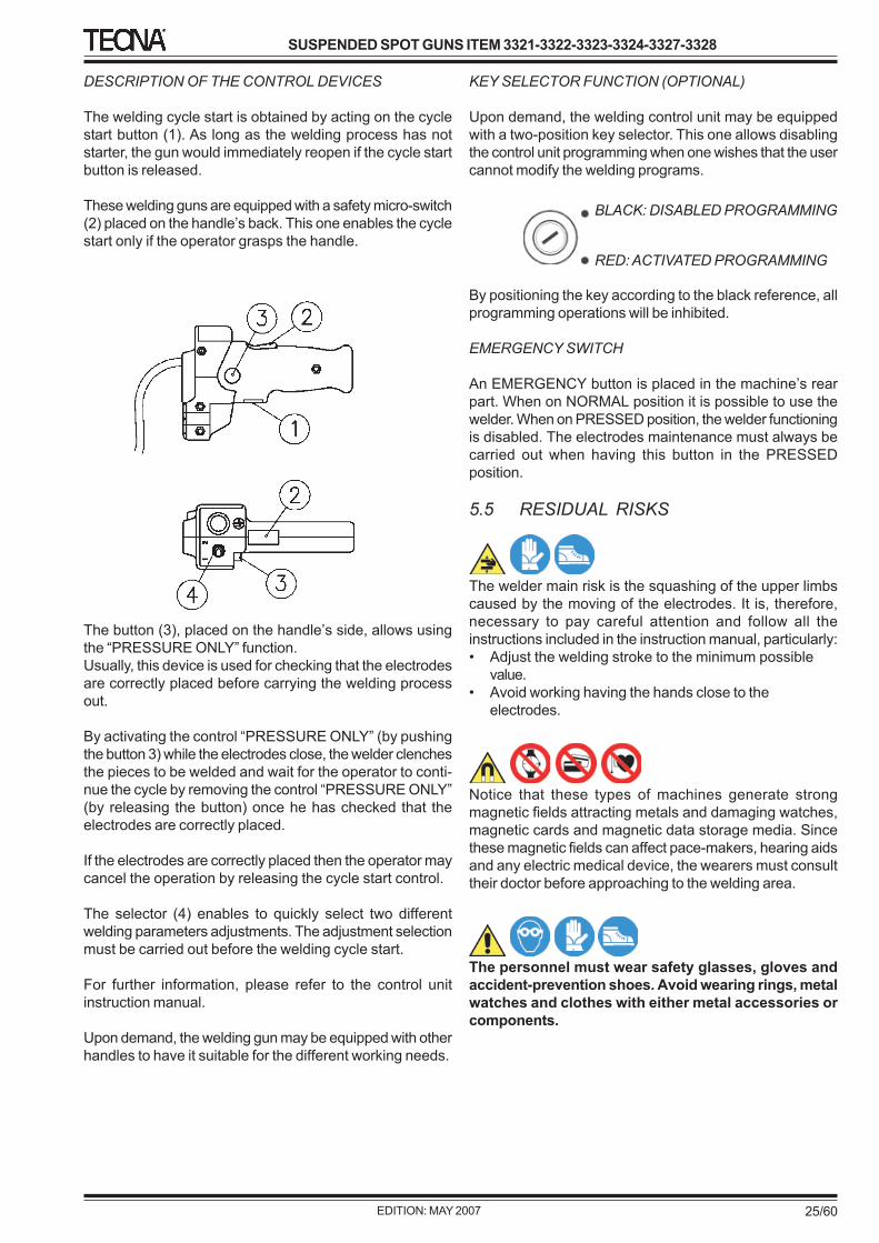
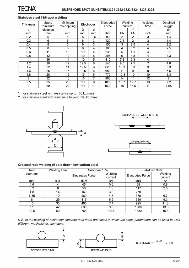
Before starting the welding process, check the weldingconditions (time, pressure, etc.). Use two off-cuts of thesheet to weld, carry out two spots at the same distanceused during the production, then remove the first and checkthe second: the spot is correct when the pulling test causesthe coming out of the weld nugget with the hole of a sheet,and the twist test shows a pure area without porosity orcauses the coming out of the nugget.
During the production it is advisable to monitor thoseparameters which can alter the working conditions, and thusthe welds quality. Always monitor the electrodes which mustalways be clean, without any deformation and must havethe proper diameter according to the work to be carried out.Check that there is no strong changing in the welder supplypressure as this could modify the force at the electrodesand thus the welding quality.
Do not use sealing products to remove water losses on theelectrodes conic connection. To facilitate the electroderemoval and to prevent from both cone seizure and waterlosses, use high conductivity grease like the one deliveredin the standard equipment.The cooling water must circulate inside the welder for a fewminutes after having completed the production in order toallow the welder cooling. To prevent from both losses andmoisture deposits, do not leave the cooling circuit openwhen the unit is not used.
Electrodes must not be used to force the clamping of thepieces to weld.
We recommend you to notice the adjustments carried outfor each type of piece. In order to make it easier, a specifictable has been added at the end of this manual.
The welding cycle start is obtained by acting on the cyclestart button (1). As long as the welding process has notstarter, the gun would immediately reopen if the cycle startbutton is released.
These welding guns are equipped with a safety micro-switch(2) placed on the handle’s back. This one enables the cyclestart only if the operator grasps the handle.
The button (3), placed on the handle’s side, allows usingthe “PRESSURE ONLY” function.Usually, this device is used for checking that the electrodesare correctly placed before carrying the welding processout.
By activating the control “PRESSURE ONLY” (by pushingthe button 3) while the electrodes close, the welder clenchesthe pieces to be welded and wait for the operator to conti-nue the cycle by removing the control “PRESSURE ONLY”(by releasing the button) once he has checked that theelectrodes are correctly placed.
If the electrodes are correctly placed then the operator maycancel the operation by releasing the cycle start control.
The selector (4) enables to quickly select two differentwelding parameters adjustments. The adjustment selectionmust be carried out before the welding cycle start.
For further information, please refer to the control unitinstruction manual.
Upon demand, the welding gun may be equipped with otherhandles to have it suitable for the different working needs.
KEY SELECTOR FUNCTION (OPTIONAL)
Upon demand, the welding control unit may be equippedwith a two-position key selector. This one allows disablingthe control unit programming when one wishes that the usercannot modify the welding programs.
By positioning the key according to the black reference, allprogramming operations will be inhibited.
EMERGENCY SWITCH
An EMERGENCY button is placed in the machine’s rearpart. When on NORMAL position it is possible to use thewelder. When on PRESSED position, the welder functioningis disabled. The electrodes maintenance must always becarried out when having this button in the PRESSEDposition.
5.5 RESIDUAL RISKS
The welder main risk is the squashing of the upper limbscaused by the moving of the electrodes. It is, therefore,necessary to pay careful attention and follow all theinstructions included in the instruction manual, particularly:• Adjust the welding stroke to the minimum possible
value.• Avoid working having the hands close to the
electrodes.
Notice that these types of machines generate strongmagnetic fields attracting metals and damaging watches,magnetic cards and magnetic data storage media. Sincethese magnetic fields can affect pace-makers, hearing aidsand any electric medical device, the wearers must consulttheir doctor before approaching to the welding area.
The personnel must wear safety glasses, gloves andaccident-prevention shoes. Avoid wearing rings, metalwatches and clothes with either metal accessories orcomponents.
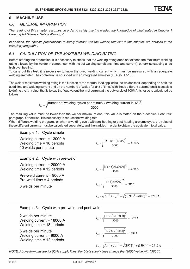
Welding current = 13000 A Welding time = 18 periods 10 welds per minute
A31843000
2130001018
thI
Example 2: Cycle with pre-weld
Welding current = 20000 A Welding time = 12 periods
Pre-weld current = 9000 A Pre-weld time = 4 periods
6 welds per minute
A30983000
220000612
1thI
A8053000
2900064
2thI
A3200)805()3098( 222
2
2
1 thththIII
Example 3: Cycle with pre-weld and post-weld
2 welds per minute Welding current = 18000 A Welding time = 18 periods
6 welds per minute Welding current = 9000 A Welding time = 12 periods
A19723000
218000218
1thI
A13943000
29000612
2thI
A2415)1394()1972( 222
2
2
1 thththIII
6 MACHINE USE6.0 GENERAL INFORMATIONThe reading of this chapter assumes, in order to safely use the welder, the knowledge of what stated in Chapter 1Paragraph 4 "General Safety Warnings".
In addition, the specific prescriptions to safely interact with the welder, relevant to this chapter, are detailed in thefollowing paragraphs.
6.1 CALCULATION OF THE MAXIMUM WELDING RATINGBefore starting the production, it is necessary to check that the welding rating does not exceed the maximum weldingrating allowed by the welder in comparison with the set welding conditions (time and current), otherwise causing a toohigh over heating.To carry out this test, it is necessary to know the used welding current which must be measured with an adequatewelding ammeter. The control unit is equipped with an integrated ammeter (TE450-TE510).
The welder maximum welding rating is the function of the thermal load applied to the welder itself, depending on both theused time and welding current and on the numbers of welds for unit of time. With these different parameters it is possibleto define the Ith value, that is to say the "equivalent thermal current at the duty cycle of 100%". Its value is calculated asfollows:
Ith
number of welding cycles per minute x (welding current in kA)
3000
2
The resulting value must be lower than the welder maximum one; this value is stated on the "Technical Features"paragraph. Otherwise, it is necessary to reduce the welding rate.When different welding programs or when a welding cycle with pre-heating or post-heating are employed, the value ofthese different currents must be calculated separately, and then added in order to obtain the equivalent total value.
NOTE: Above formulas are for 50Hz supply lines. For 60Hz supply lines change the "3000" value with "3600".
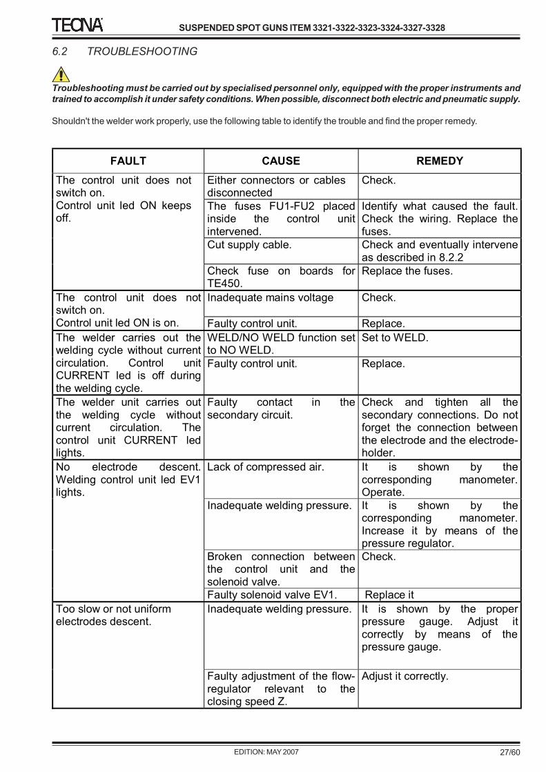
Troubleshooting must be carried out by specialised personnel only, equipped with the proper instruments andtrained to accomplish it under safety conditions. When possible, disconnect both electric and pneumatic supply.
Shouldn't the welder work properly, use the following table to identify the trouble and find the proper remedy.
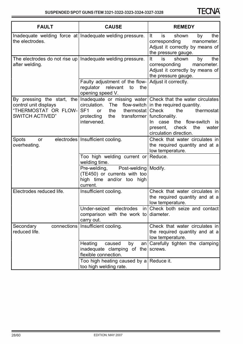
FAULT CAUSE REMEDY
Either connectors or cables disconnected
Check.
The fuses FU1-FU2 placed inside the control unit intervened.
Identify what caused the fault. Check the wiring. Replace the fuses.
Cut supply cable. Check and eventually intervene as described in 8.2.2
The control unit does not switch on. Control unit led ON keeps off.
Check fuse on boards for TE450.
Replace the fuses.
Inadequate mains voltage
Check.
The control unit does not switch on. Control unit led ON is on. Faulty control unit. Replace.
WELD/NO WELD function set to NO WELD.
Set to WELD. The welder carries out the welding cycle without current circulation. Control unit CURRENT led is off during the welding cycle.
Faulty control unit. Replace.
The welder unit carries out the welding cycle without current circulation. The control unit CURRENT led lights.
Faulty contact in the secondary circuit.
Check and tighten all the secondary connections. Do not forget the connection between the electrode and the electrode-holder.
Lack of compressed air. It is shown by the corresponding manometer. Operate.
Inadequate welding pressure. It is shown by the corresponding manometer. Increase it by means of the pressure regulator.
Broken connection between the control unit and the solenoid valve.
Check.
No electrode descent. Welding control unit led EV1 lights.
Faulty solenoid valve EV1. Replace it
Inadequate welding pressure. It is shown by the proper pressure gauge. Adjust it correctly by means of the pressure gauge.
Too slow or not uniform electrodes descent.
Faulty adjustment of the flow-regulator relevant to the closing speed Z.
Inadequate welding pressure. It is shown by the corresponding manometer. Adjust it correctly by means of the pressure gauge.
Inadequate welding pressure. It is shown by the corresponding manometer. Adjust it correctly by means of the pressure gauge.
The electrodes do not rise up after welding.
Faulty adjustment of the flow-regulator relevant to the opening speed V.
Adjust it correctly.
By pressing the start, the control unit displays “THERMOSTAT OR FLOW-SWITCH ACTIVED”
Inadequate or missing water circulation. The flow-switch SF1 or the thermostat protecting the transformer intervened.
Check that the water circulates in the required quantity. Check the thermostat functionality. In case the flow-switch is present, check the water circulation direction.
Insufficient cooling. Check that water circulates in the required quantity and at a low temperature.
Too high welding current or welding time.
Reduce.
Spots or electrodes overheating.
Pre-welding, Post-welding (TE450) or currents with too high time and/or too high current.
Modify.
Insufficient cooling. Check that water circulates in the required quantity and at a low temperature.
Electrodes reduced life.
Under-seized electrodes in comparison with the work to carry out.
Check both seize and contact diameter.
Insufficient cooling. Check that water circulates in the required quantity and at a low temperature.
Heating caused by an inadequate clamping of the flexible connection.
Carefully tighten the clamping screws.
Secondary connections reduced life.
Too high heating caused by a too high welding rate.
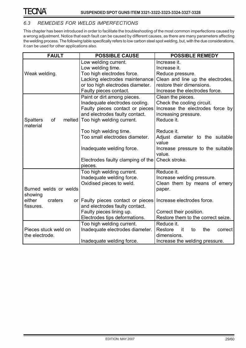
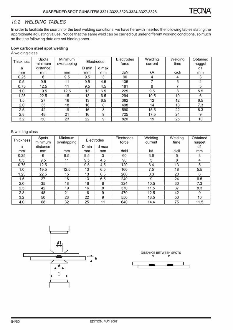
6.3 REMEDIES FOR WELDS IMPERFECTIONSThis chapter has been introduced in order to facilitate the troubleshooting of the most common imperfections caused bya wrong adjustment. Notice that each fault can be caused by different causes, as there are many parameters affectingthe welding process. The following table specifically refers to low carbon steel spot welding, but, with the due considerations,it can be used for other applications also.
FAULT POSSIBLE CAUSE POSSIBLE REMEDY
Low welding current. Increase it. Low welding time. Increase it. Weak welding. Too high electrodes force. Reduce pressure. Lacking electrodes maintenance
or too high electrodes diameter. Clean and line up the electrodes, restore their dimensions.
Faulty pieces contact. Increase the electrodes force.
Paint or dirt among pieces. Clean the pieces. Inadequate electrodes cooling. Check the cooling circuit. Faulty pieces contact or pieces
and electrodes faulty contact. Increase the electrodes force by increasing pressure.
Spatters of melted material
Too high welding current. Reduce it.
Too high welding time. Reduce it. Too small electrodes diameter. Adjust diameter to the suitable
value Inadequate welding force. Increase pressure to the suitable
value. Electrodes faulty clamping of the
pieces. Check stroke.
Too high welding current. Reduce it. Inadequate welding force. Increase welding pressure. Burned welds or welds showing
Oxidised pieces to weld. Clean them by means of emery paper.
either craters or fissures.
Faulty pieces contact or pieces and electrodes faulty contact.
Increase electrodes force.
Faulty pieces lining up. Correct their position. Electrodes tips deformations. Restore them to the correct seize.
Too high welding current. Reduce it. Pieces stuck weld on the electrode.
Inadequate electrodes diameter. Restore it to the correct dimensions.
Inadequate welding force. Increase the welding pressure.
7 INSTRUCTIONS FOR THE ADJUSTMENTS7.0 GENERAL INFORMATIONThe reading of this chapter assumes, in order to safely use the welder, the knowledge of what stated in Chapter 1Paragraph 4 "General Safety Warnings".
In addition, the specific prescriptions to safely interact with the welder, relevant to this chapter, are detailed in thefollowing paragraphs.
7.1 STANDARD ACCESSORIESThe welder is supplied equipped with the following accessories:N° 1 Allen wrench set.N° 1 Electrodes extractor.N° 1 Pin driver 3 (for Item 3323).N° 1 Stroke adjustment key (for Items 3321 - 3322 - 3324 - 3327- 3328)N° 1 High conductivity grease sample.N° 1 Rotating supplementary handleN° 1 Filter-regulator pneumatic group with cutting device.N° 1 Welding control unit instruction manual.N° 1 Welder installation and use manual.N° 1 Technical documentation booklet.N° 1 Clips set, replacement screws and little accessories.
Check that the machine is complete with all the standard accessories; promptly inform the manufacturer of all theeventual missing parts.
7.2 MECHANICAL SET UP
7.2.1 ARMS SELECTION AND REPLACEMENT
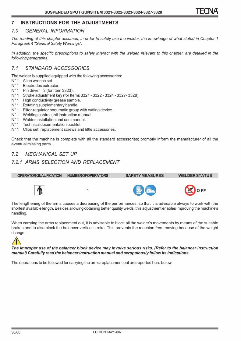
OPERATOR QUALIFICATION NUMBER OF OPERATORS SAFETY MEASURES WELDER STATUS
1 O FF
The lengthening of the arms causes a decreasing of the performances, so that it is advisable always to work with theshortest available length. Besides allowing obtaining better quality welds, this adjustment enables improving the machine'shandling.
When carrying the arms replacement out, it is advisable to block all the welder's movements by means of the suitablebrakes and to also block the balancer vertical stroke. This prevents the machine from moving because of the weightchange.
The improper use of the balancer block device may involve serious risks. (Refer to the balancer instructionmanual) Carefully read the balancer instruction manual and scrupulously follow its indications.
The operations to be followed for carrying the arms replacement out are reported here below.
ARMS REPLACEMENT IN THE "C" TYPE SUSPENDED WELDING GUNS ITEM 3323The secondary surface increase causes a performances decrease. Therefore, it is always advisable to use those armssets allowing the work to be done but having the smallest area. Besides allowing obtaining better quality welds, thisadjustment enables improving the machine's handling.When carrying the arms replacement out, it is advisable to block the welder vertical movement by means of the balancerblock control. This prevents the machine from moving because of the weight change. The improper use of the balancerblock device may involve serious risks. (Refer to the balancer instruction manual) Carefully read the balancerinstruction manual and scrupulously follow its indications.
The arms sets and electrodes replacement must always be carried out while the water cutting valves P are closedand the machine front part faces downwards so to prevent the water from entering the welder.
In case of water entering the welder, immediately stop the electrical supply and proceed with both loss and waterremoval.
Replacement of the movable electrode-holder (C)
1 Stop the electrical supply at the main switch supplying the welder.2 Close the pneumatic supply and discharge the remaining air. The cutting device supplied with the machine
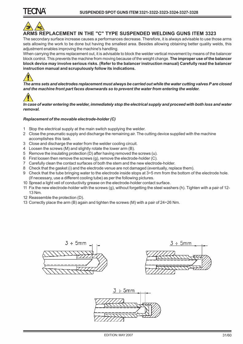
accomplishes this task.3 Close and discharge the water from the welder cooling circuit.4 Loosen the screws (M) and slightly rotate the lower arm (B).5 Remove the insulating protection (D) after having removed the screws (u).6 First loosen then remove the screws (g), remove the electrode-holder (C).7 Carefully clean the contact surfaces of both the stem and the new electrode-holder.8 Check that the gasket (i) and the electrode venue are not damaged (eventually, replace them).9 Check that the tube bringing water to the electrode inside stops at 3÷5 mm from the bottom of the electrode hole.
(If necessary, use a different cooling tube) as per the following pictures.10 Spread a light veil of conductivity grease on the electrode-holder contact surface.11 Fix the new electrode-holder with the screws (g), without forgetting the steel washers (h). Tighten with a pair of 12-
13 Nm.12 Reassemble the protection (D).13 Correctly place the arm (B) again and tighten the screws (M) with a pair of 24÷26 Nm.
1 Stop the electrical supply at the main switch supplying the welder.2 Close the pneumatic supply and discharge the remaining air. The cutting device supplied with the machine
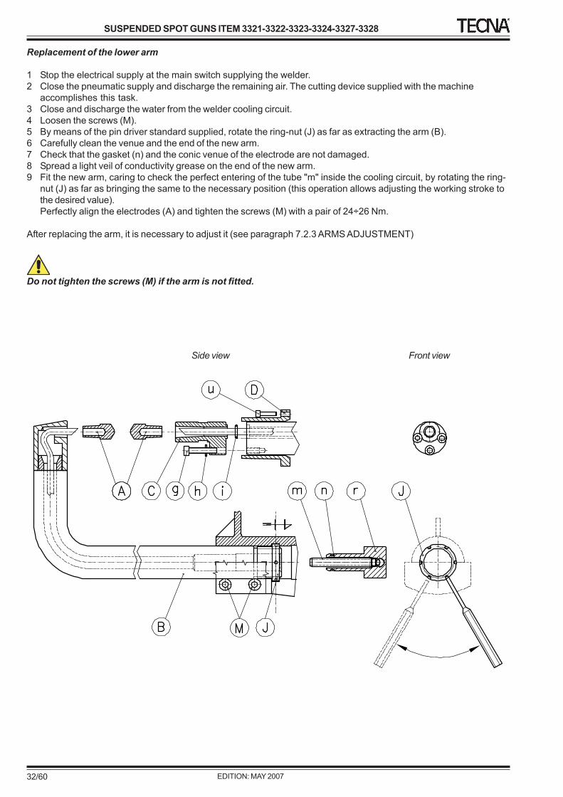
accomplishes this task.3 Close and discharge the water from the welder cooling circuit.4 Loosen the screws (M).5 By means of the pin driver standard supplied, rotate the ring-nut (J) as far as extracting the arm (B).6 Carefully clean the venue and the end of the new arm.7 Check that the gasket (n) and the conic venue of the electrode are not damaged.8 Spread a light veil of conductivity grease on the end of the new arm.9 Fit the new arm, caring to check the perfect entering of the tube "m" inside the cooling circuit, by rotating the ring-
nut (J) as far as bringing the same to the necessary position (this operation allows adjusting the working stroke tothe desired value).Perfectly align the electrodes (A) and tighten the screws (M) with a pair of 24÷26 Nm.
After replacing the arm, it is necessary to adjust it (see paragraph 7.2.3 ARMS ADJUSTMENT)
Do not tighten the screws (M) if the arm is not fitted.
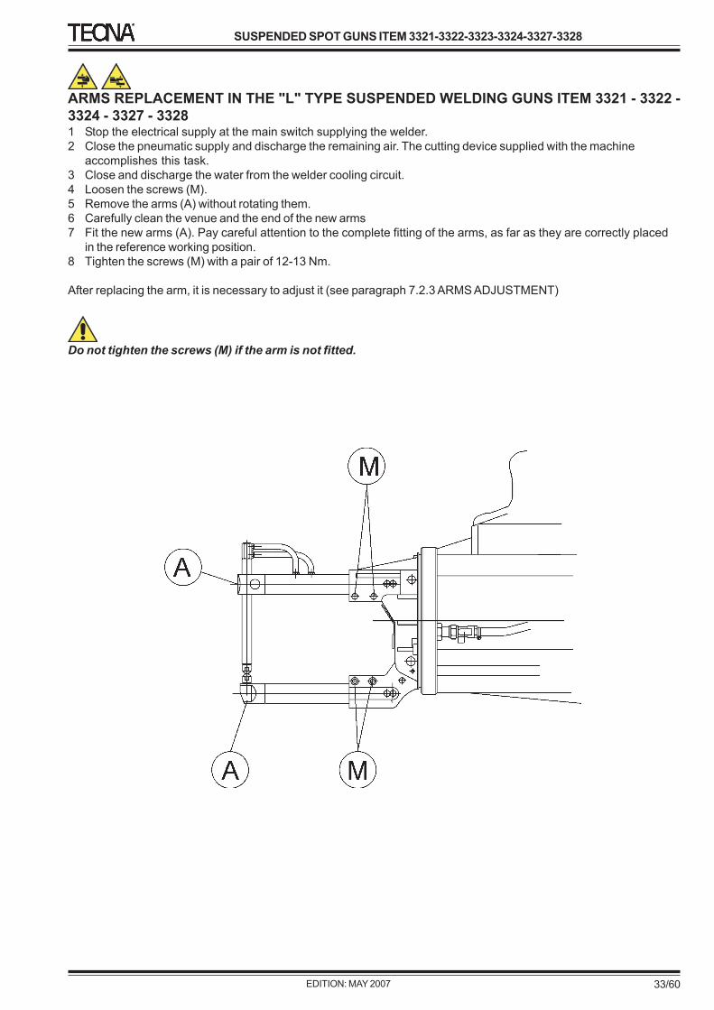
ARMS REPLACEMENT IN THE "L" TYPE SUSPENDED WELDING GUNS ITEM 3321 - 3322 -3324 - 3327 - 33281 Stop the electrical supply at the main switch supplying the welder.2 Close the pneumatic supply and discharge the remaining air. The cutting device supplied with the machine
accomplishes this task.3 Close and discharge the water from the welder cooling circuit.4 Loosen the screws (M).5 Remove the arms (A) without rotating them.6 Carefully clean the venue and the end of the new arms7 Fit the new arms (A). Pay careful attention to the complete fitting of the arms, as far as they are correctly placed
in the reference working position.8 Tighten the screws (M) with a pair of 12-13 Nm.
After replacing the arm, it is necessary to adjust it (see paragraph 7.2.3 ARMS ADJUSTMENT)
Do not tighten the screws (M) if the arm is not fitted.
OPERATOR QUALIFICATION NUMBER OF OPERATORS SAFETY MEASURES WELDER STATUS
1 OFF
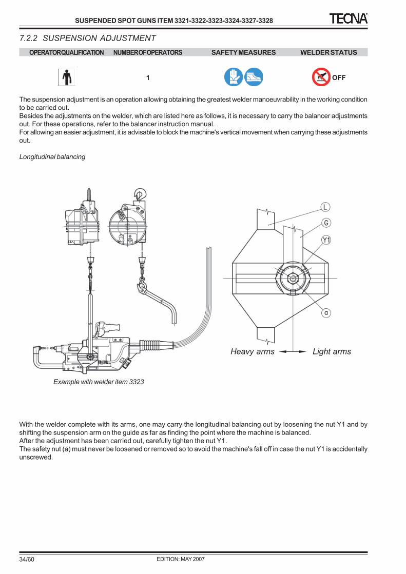
The suspension adjustment is an operation allowing obtaining the greatest welder manoeuvrability in the working conditionto be carried out.Besides the adjustments on the welder, which are listed here as follows, it is necessary to carry the balancer adjustmentsout. For these operations, refer to the balancer instruction manual.For allowing an easier adjustment, it is advisable to block the machine's vertical movement when carrying these adjustmentsout.
Longitudinal balancing
With the welder complete with its arms, one may carry the longitudinal balancing out by loosening the nut Y1 and byshifting the suspension arm on the guide as far as finding the point where the machine is balanced.After the adjustment has been carried out, carefully tighten the nut Y1.The safety nut (a) must never be loosened or removed so to avoid the machine's fall off in case the nut Y1 is accidentallyunscrewed.
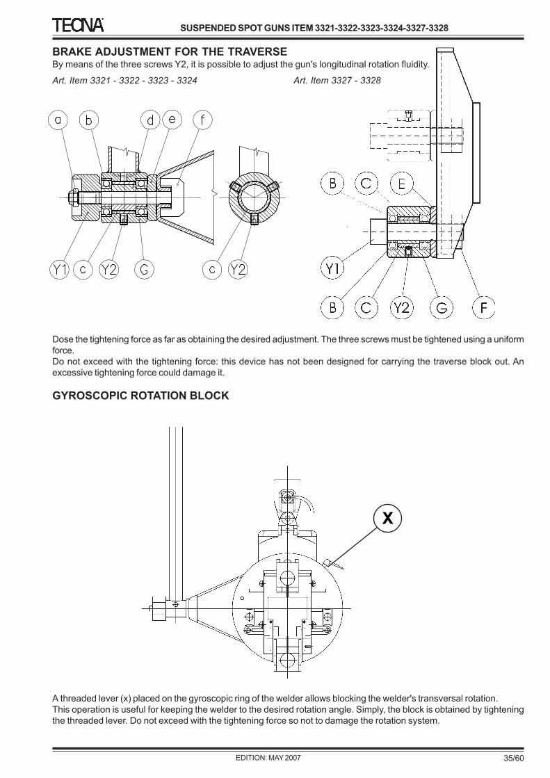
BRAKE ADJUSTMENT FOR THE TRAVERSEBy means of the three screws Y2, it is possible to adjust the gun's longitudinal rotation fluidity.
Dose the tightening force as far as obtaining the desired adjustment. The three screws must be tightened using a uniformforce.Do not exceed with the tightening force: this device has not been designed for carrying the traverse block out. Anexcessive tightening force could damage it.
GYROSCOPIC ROTATION BLOCK
A threaded lever (x) placed on the gyroscopic ring of the welder allows blocking the welder's transversal rotation.This operation is useful for keeping the welder to the desired rotation angle. Simply, the block is obtained by tighteningthe threaded lever. Do not exceed with the tightening force so not to damage the rotation system.
OPERATOR QUALIFICATION NUMBER OF OPERATORS SAFETY MEASURES WELDER STATUS
1 ON
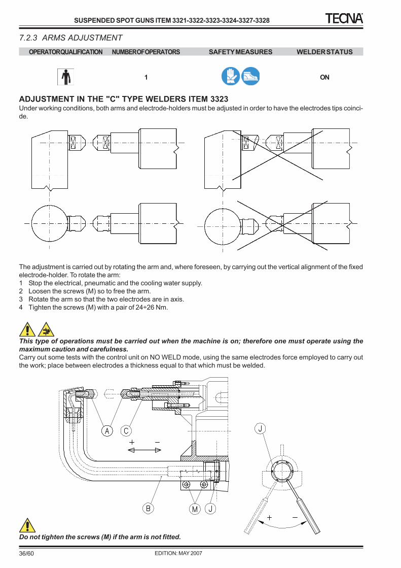
ADJUSTMENT IN THE "C" TYPE WELDERS ITEM 3323Under working conditions, both arms and electrode-holders must be adjusted in order to have the electrodes tips coinci-de.
The adjustment is carried out by rotating the arm and, where foreseen, by carrying out the vertical alignment of the fixedelectrode-holder. To rotate the arm:1 Stop the electrical, pneumatic and the cooling water supply.2 Loosen the screws (M) so to free the arm.3 Rotate the arm so that the two electrodes are in axis.4 Tighten the screws (M) with a pair of 24÷26 Nm.
This type of operations must be carried out when the machine is on; therefore one must operate using themaximum caution and carefulness.Carry out some tests with the control unit on NO WELD mode, using the same electrodes force employed to carry outthe work; place between electrodes a thickness equal to that which must be welded.
Do not tighten the screws (M) if the arm is not fitted.
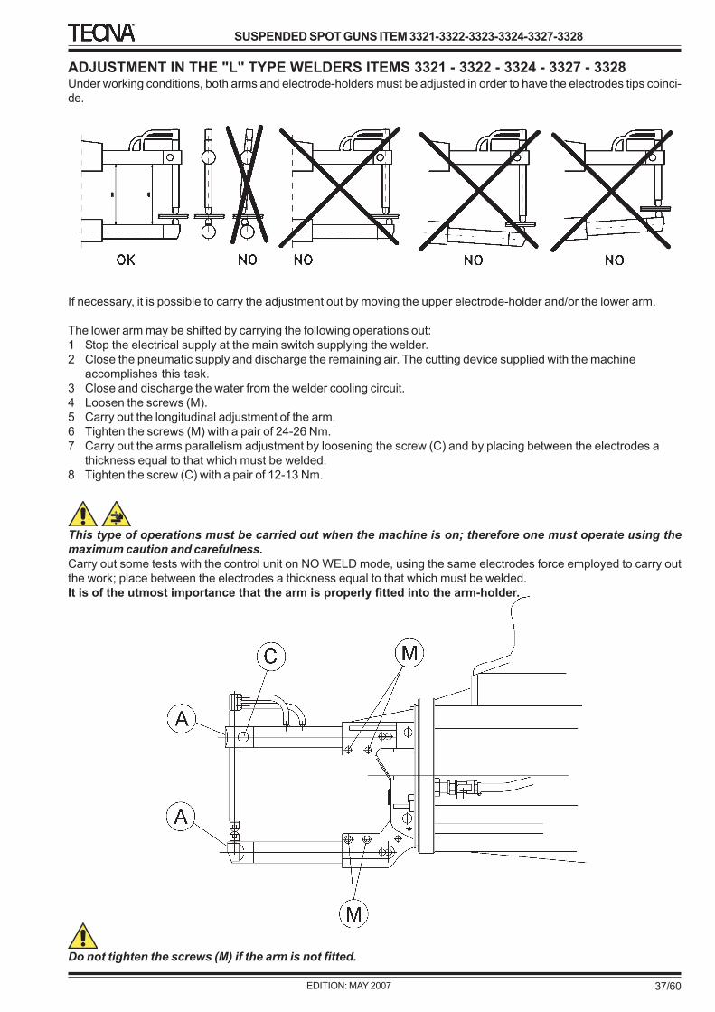
ADJUSTMENT IN THE "L" TYPE WELDERS ITEMS 3321 - 3322 - 3324 - 3327 - 3328Under working conditions, both arms and electrode-holders must be adjusted in order to have the electrodes tips coinci-de.
If necessary, it is possible to carry the adjustment out by moving the upper electrode-holder and/or the lower arm.
The lower arm may be shifted by carrying the following operations out:1 Stop the electrical supply at the main switch supplying the welder.2 Close the pneumatic supply and discharge the remaining air. The cutting device supplied with the machine
accomplishes this task.3 Close and discharge the water from the welder cooling circuit.4 Loosen the screws (M).5 Carry out the longitudinal adjustment of the arm.6 Tighten the screws (M) with a pair of 24-26 Nm.7 Carry out the arms parallelism adjustment by loosening the screw (C) and by placing between the electrodes a
thickness equal to that which must be welded.8 Tighten the screw (C) with a pair of 12-13 Nm.
This type of operations must be carried out when the machine is on; therefore one must operate using themaximum caution and carefulness.Carry out some tests with the control unit on NO WELD mode, using the same electrodes force employed to carry outthe work; place between the electrodes a thickness equal to that which must be welded.It is of the utmost importance that the arm is properly fitted into the arm-holder.
Do not tighten the screws (M) if the arm is not fitted.
OPERATOR QUALIFICATION NUMBER OF OPERATORS SAFETY MEASURES WELDER STATUS
1 OFF
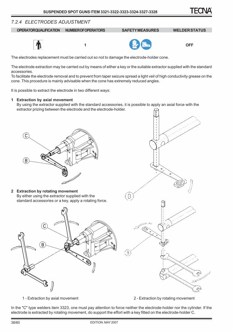
The electrodes replacement must be carried out so not to damage the electrode-holder cone.
The electrode extraction may be carried out by means of either a key or the suitable extractor supplied with the standardaccessories.To facilitate the electrode removal and to prevent from taper seizure spread a light veil of high conductivity grease on thecone. This procedure is mainly advisable when the cone has extremely reduced angles.
It is possible to extract the electrode in two different ways:
1 Extraction by axial movementBy using the extractor supplied with the standard accessories, it is possible to apply an axial force with theextractor prizing between the electrode and the electrode-holder.
2 Extraction by rotating movementBy either using the extractor supplied with thestandard accessories or a key, apply a rotating force.
1 - Extraction by axial movement 2 - Extraction by rotating movement
In the "C" type welders item 3323, one must pay attention to force neither the electrode-holder nor the cylinder. If theelectrode is extracted by rotating movement, do support the effort with a key fitted on the electrode-holder C.
This type of operations must be carried out when the machine is on; therefore one must operate using themaximum caution and carefulness.
To prevent from cooling water leakage when the machine is off, close the circuit delivery taps placed on board themachine.
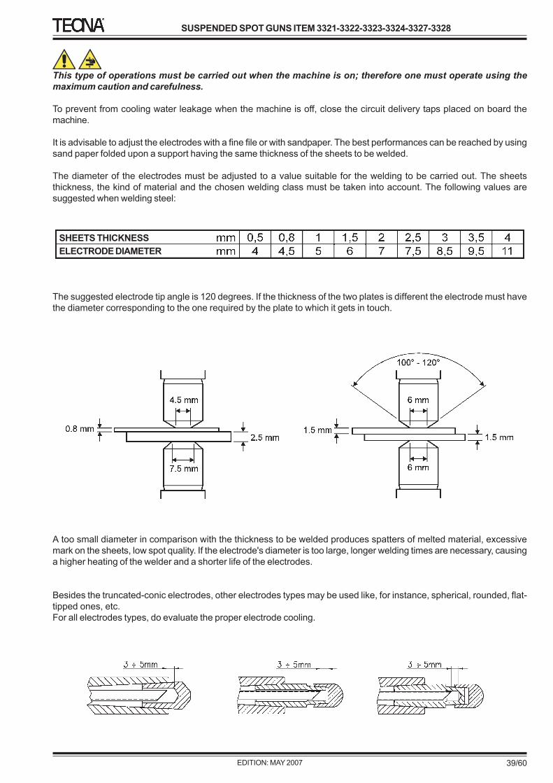
It is advisable to adjust the electrodes with a fine file or with sandpaper. The best performances can be reached by usingsand paper folded upon a support having the same thickness of the sheets to be welded.
The diameter of the electrodes must be adjusted to a value suitable for the welding to be carried out. The sheetsthickness, the kind of material and the chosen welding class must be taken into account. The following values aresuggested when welding steel:
The suggested electrode tip angle is 120 degrees. If the thickness of the two plates is different the electrode must havethe diameter corresponding to the one required by the plate to which it gets in touch.
A too small diameter in comparison with the thickness to be welded produces spatters of melted material, excessivemark on the sheets, low spot quality. If the electrode's diameter is too large, longer welding times are necessary, causinga higher heating of the welder and a shorter life of the electrodes.
Besides the truncated-conic electrodes, other electrodes types may be used like, for instance, spherical, rounded, flat-tipped ones, etc.For all electrodes types, do evaluate the proper electrode cooling.
OPERATOR QUALIFICATION NUMBER OF OPERATORS SAFETY MEASURES WELDER STATUS
1 OFF
Adjust the working stroke to the minimum possible value to obtain.1 Reduced accident possibilities.2 Reduced noise.3 Bigger productivity.4 Faster force rise time on the pieces to be welded.5 Higher follow up.6 Higher working precision.7 Reduced air consumption.
The stroke adjustment must be carried out in order to avoid that the cylinder reaches the end of the stroke, limiting orclearing, by doing so, the force on the piece. Remind that both electrodes wear and arms deflection increase the workingstroke.
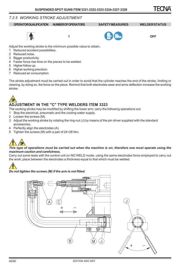
ADJUSTMENT IN THE "C" TYPE WELDERS ITEM 3323The working stroke may be modified by shifting the lower arm; carry the following operations out:1 Stop the electrical, pneumatic and the cooling water supply.2 Loosen the screws (M).3 Adjust the working stroke by rotating the ring-nut (J) by means of the pin driver supplied with the standard
accessories.4 Perfectly align the electrodes (A).5 Tighten the screws (M) with a pair of 24÷26 Nm.
This type of operations must be carried out when the machine is on; therefore one must operate using themaximum caution and carefulness.Carry out some tests with the control unit on NO WELD mode, using the same electrodes force employed to carry outthe work; place between the electrodes a thickness equal to that which must be welded.
Do not tighten the screws (M) if the arm is not fitted.
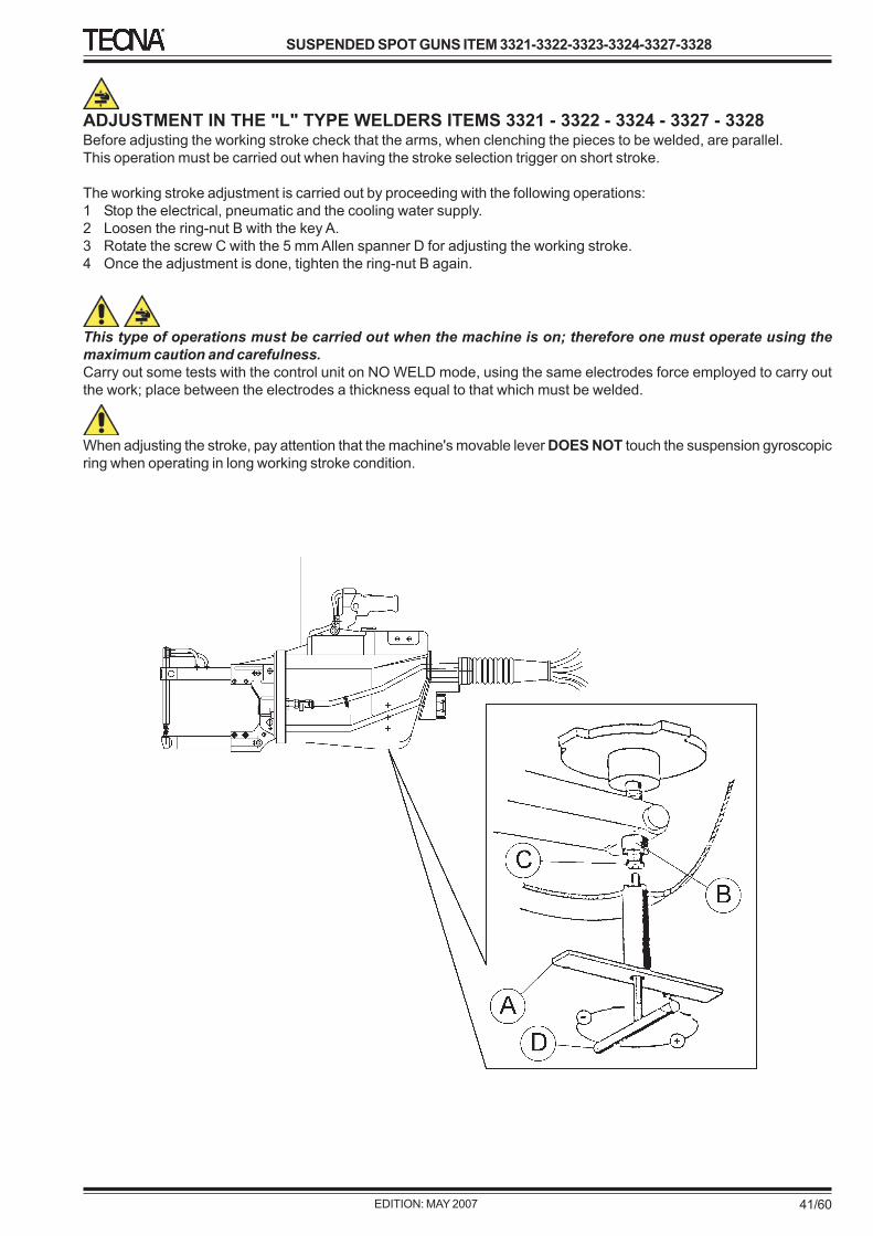
ADJUSTMENT IN THE "L" TYPE WELDERS ITEMS 3321 - 3322 - 3324 - 3327 - 3328Before adjusting the working stroke check that the arms, when clenching the pieces to be welded, are parallel.This operation must be carried out when having the stroke selection trigger on short stroke.
The working stroke adjustment is carried out by proceeding with the following operations:1 Stop the electrical, pneumatic and the cooling water supply.2 Loosen the ring-nut B with the key A.3 Rotate the screw C with the 5 mm Allen spanner D for adjusting the working stroke.4 Once the adjustment is done, tighten the ring-nut B again.
This type of operations must be carried out when the machine is on; therefore one must operate using themaximum caution and carefulness.Carry out some tests with the control unit on NO WELD mode, using the same electrodes force employed to carry outthe work; place between the electrodes a thickness equal to that which must be welded.
When adjusting the stroke, pay attention that the machine's movable lever DOES NOT touch the suspension gyroscopicring when operating in long working stroke condition.
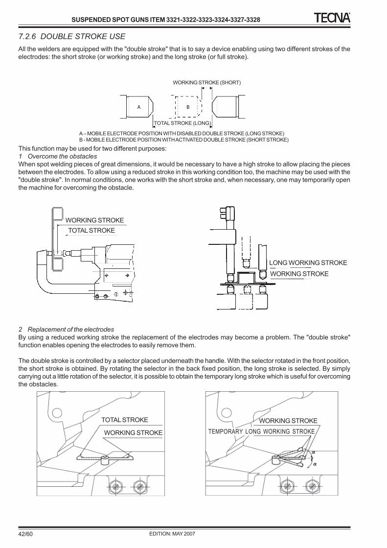
7.2.6 DOUBLE STROKE USEAll the welders are equipped with the "double stroke" that is to say a device enabling using two different strokes of theelectrodes: the short stroke (or working stroke) and the long stroke (or full stroke).
This function may be used for two different purposes:1 Overcome the obstaclesWhen spot welding pieces of great dimensions, it would be necessary to have a high stroke to allow placing the piecesbetween the electrodes. To allow using a reduced stroke in this working condition too, the machine may be used with the"double stroke". In normal conditions, one works with the short stroke and, when necessary, one may temporarily openthe machine for overcoming the obstacle.
2 Replacement of the electrodesBy using a reduced working stroke the replacement of the electrodes may become a problem. The "double stroke"function enables opening the electrodes to easily remove them.
The double stroke is controlled by a selector placed underneath the handle. With the selector rotated in the front position,the short stroke is obtained. By rotating the selector in the back fixed position, the long stroke is selected. By simplycarrying out a little rotation of the selector, it is possible to obtain the temporary long stroke which is useful for overcomingthe obstacles.
A – MOBILE ELECTRODE POSITION WITH DISABLED DOUBLE STROKE (LONG STROKE)B - MOBILE ELECTRODE POSITION WITH ACTIVATED DOUBLE STROKE (SHORT STROKE)
WORKING STROKE (SHORT)
TOTAL STROKE (LONG)
WORKING STROKETOTAL STROKE
LONG WORKING STROKE
WORKING STROKE
WORKING STROKETEMPORARY LONG WORKING STROKEWORKING STROKE
OPERATOR QUALIFICATION NUMBER OF OPERATORS SAFETY MEASURES WELDER STATUS
1 NO WELD
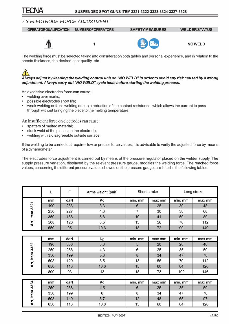
The welding force must be selected taking into consideration both tables and personal experience, and in relation to thesheets thickness, the desired spot quality, etc.
Always adjust by keeping the welding control unit on "NO WELD" in order to avoid any risk caused by a wrongadjustment. Always carry out "NO WELD" cycle tests before starting the welding process.
An excessive electrodes force can cause:• welding over marks;• possible electrodes short life;• weak welding or false welding due to a reduction of the contact resistance, which allows the current to pass
through without bringing the piece to the melting temperature.
An insufficient force on electrodes can cause:• spatters of melted material;• stuck weld of the pieces on the electrode;• welding with a disagreeable outside surface.
If the welding to be carried out requires low or precise force values, it is advisable to verify the adjusted force by meansof a dynamometer.
The electrodes force adjustment is carried out by means of the pressure regulator placed on the welder supply. Thesupply pressure variation, displayed by the relevant pressure gauge, modifies the welding force. The reached forcevalues, concerning the different pressure values showed on the pressure gauge, are listed in the following tables.
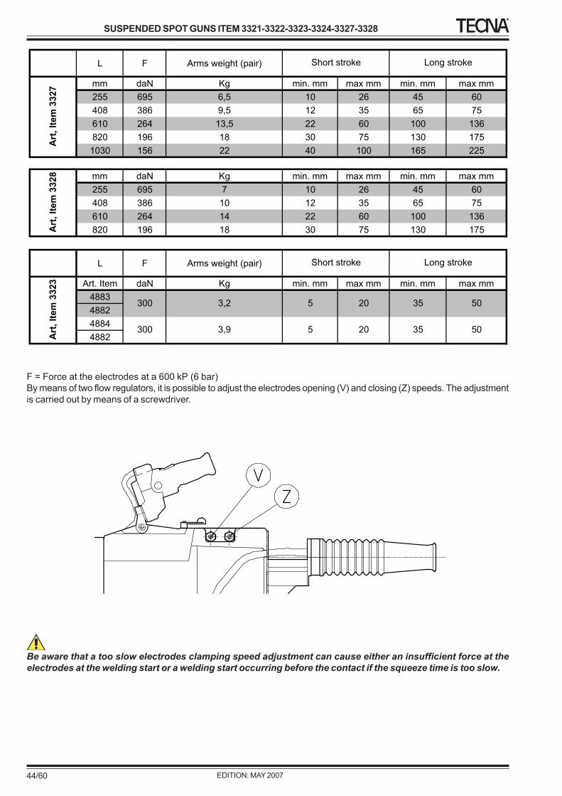
F = Force at the electrodes at a 600 kP (6 bar)By means of two flow regulators, it is possible to adjust the electrodes opening (V) and closing (Z) speeds. The adjustmentis carried out by means of a screwdriver.
Be aware that a too slow electrodes clamping speed adjustment can cause either an insufficient force at theelectrodes at the welding start or a welding start occurring before the contact if the squeeze time is too slow.
7.4 WORKING PROGRAM ADJUSTMENTThis operation enables to choose the welding parameters and to enter them directly on the welding control.Select parameters from table or personal experience, taking into consideration the plate thickness, the welding desiredquality etc.We suggest using short welding times to reduce the electrodes heating, thus increasing their life, at the same timeavoiding oxidation on the contact surfaces.The best quality welds are obtained by using welding times as short as possible with high current and high electrodeforce.Notice that when operating pieces with different thickness, the welding parameters to be used are those which refer tothe lower thickness.
This welder can operate under two different working modes: single cycle and automatic cycle. The adjustment instructionsare stated on the welding control unit instruction manual. When working in automatic cycle, as long as the start-cyclecontrol device is activated, the welder will repeat welding cycles at the settled off time. In single cycle, even though thestart device is kept activated, the welding unit will stop after having carried out a single cycle; to carry out the next one,it is necessary first to release the device and then press it once again.
To avoid any danger, use the automatic cycle only when it is really necessary; it must not be activated when it isnot used.
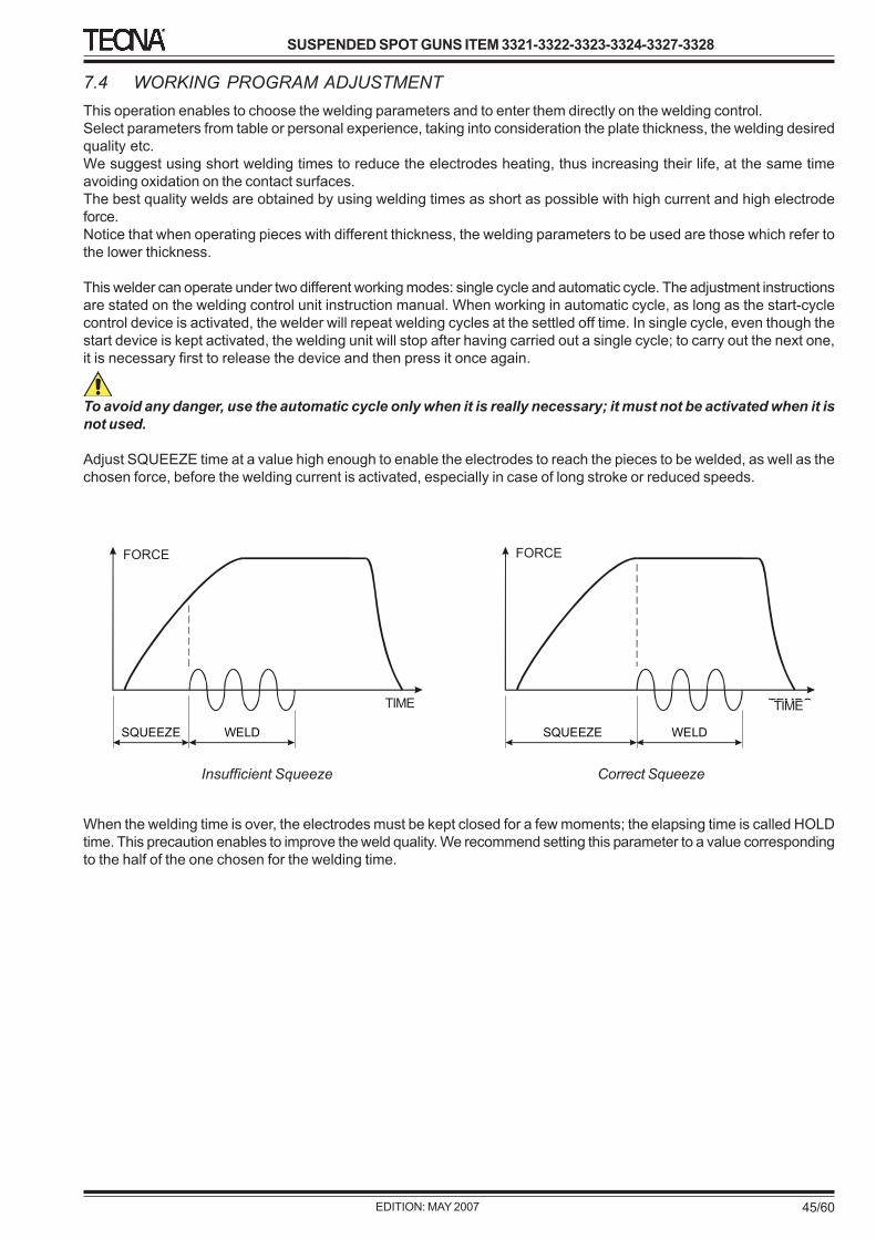
Adjust SQUEEZE time at a value high enough to enable the electrodes to reach the pieces to be welded, as well as thechosen force, before the welding current is activated, especially in case of long stroke or reduced speeds.
When the welding time is over, the electrodes must be kept closed for a few moments; the elapsing time is called HOLDtime. This precaution enables to improve the weld quality. We recommend setting this parameter to a value correspondingto the half of the one chosen for the welding time.
8 MAINTENANCE8.0 GENERAL INFORMATIONThe reading of this chapter assumes, in order to safely usethe welder, the knowledge of what stated in Chapter 1Paragraph 4 "General Safety Warnings".
In addition, the specific prescriptions to safely interact withthe welder, relevant to this chapter, are detailed in thefollowing paragraphs.
8.1 ORDINARY MAINTENANCE
OPERATOR QUALIFICATION NUMBER OF OPERATORS
1
SAFETY MEASURES WELDER STATUS
OFF
This chapter states the necessary maintenance operationsto be carried out for:1 keeping the welding unit safe operating and preserving
its efficiency;2 avoiding the most common causes of wrong working
worsening the welding quality.
During the maintenance operations it is advisable toblock the balancer (for further information, check thebalancer instruction manual).
We remind that, besides carrying the machinemaintenance operations out, it is necessary to carry thebalancer maintenance out by following the instructionsincluded in the relevant instruction manual.
For all interventions involving disassembling the machine,kindly, refer to the exploded views showing the parts andtheir position. We recommend maximum cleaning,oxidations removal, use of lubricants and prescribedproducts.
LUBRICANTSThe suggested lubricants for the welder are listed in thetechnical documentation.• POLIMER 400 GREASE or equivalent• MOLIKOTE "G-N PLUS" GREASE• VANOFRIX 430 CONDUCTIVITY GREASE or
equivalent (remove the exceeding grease aftertightening the parts so to prevent from short-circuits)
• MINERAL or SYNTHETIC OIL with MOLIKOTE "M 55PLUS" additive at 10%.
GENERAL WARNINGS
Always disconnect both electrical and pneumaticsupply before carrying out the following maintenanceoperations.
• The secondary circuit contacts must be kept clean.Fine sandpaper can be used for cleaning. Aftercleaning, apply a light veil of conductivity grease onthe contact parts. Once the parts are assembled,remove the exceeding grease so to prevent from short-circuits
• Always keep the screws of arms, electrode-holders,and rigid/flexible connections well tightened.
• Periodically (each 3 months), grease the gyroscopicring venue by means of the proper greaser placed onthe ring itself. Carefully, remove the exceeding grease.
• Check that the flexible connection is undamaged.Eventual broken laminates must be removed so toprevent them from causing short-circuits. If the flexibleconnection is excessively worn out, replace it.
• Keep welder clean from dirt and metal scrapsattracted by the magnetic field generated by thewelder during the operation.
• Neither washing the welding unit with jets of waterwhich could enter it, nor use strong solvents, thinner,nor benzine that could damage either the painting orthe machine plastic components.
ELECTRODES MAINTENANCE
Electrodes maintenance must be carried out with thewelder switched off.
• When operating, the electrodes must be kept cleanand their diameter must be kept suitable for the workto be carried out. Too worn electrodes must bereplaced.
• When replacing electrodes, check that the tubebringing water to the electrode inside stops at a fewmm from the bottom of the electrode hole.
• Do not use sealing products to remove water leakageon the electrode taper. To facilitate the electroderemoval and to prevent from both taper seizure andleakage, use high conductivity grease like the onedelivered in the standard equipment.
• Before replacing the electrodes, stop the water supplycircuit or stop the electrodes cooling circuit by meansof the valves placed on the welder side.
WARNING! Before starting the production again, alwayscheck that the cooling circuit has been reopened.
The pneumatic circuit maintenance must be carried outby specialised personnel only, trained to accomplish itunder safety conditions. When possible, maintenanceoperations must be carried out with the welder switchedoff and disconnected from the pneumatic supply, withthe circuit free from left air.
• In case of air leakage, immediately stop operating andremove it.
• Check the proper functioning of the automatic air filterdischarge.
• Check pressure gauge calibration.• Check the status of both compressed air and
corresponding connections.• Watch out not to introduce either dirt or dust in the
machine which may cause serious damages, stop orquick wear.
COOLING CIRCUIT MAINTENANCE
The cooling circuit maintenance must be carried outby specialised personnel only, trained to accomplish itunder safety conditions. When possible, maintenanceoperations must be carried out with the welderdisconnected from both electric and pneumatic supply.
• Check that cooling water circulates freely and in therequired quantity, and that the input temperature isincluded within 10 and 30°C.
• Check the status of both water hoses and thecorresponding connections.
• If, during the winter terms, the welder must bestored up in cool rooms, it is necessary tocarefully drain the cooling circuit to prevent frompossible damages caused by frozen water.
ELECTRIC CIRCUIT MAINTENANCE
The electric circuit maintenance must be carried outonly by specialised personnel trained to accomplish itunder safety conditions. Disconnect electric mainsbefore carrying out the following instructions as mortaldischarges may be received from the supply.
• Frequently, check the welder supply cable status.Pay special attention to the points where the cablegets mainly stressed or exposed to possiblemechanical damages. Replace it in case cracks,cuts, heavy abrasions are found.
• Check that the welder is connected to the protectionconductor, that the ground wire inside the supplycable is not cut.
• Periodically check the ground efficiency.
• Often check both the status and the properfunctioning of the control devices and of thecorresponding connecting cables.
• Frequently check the proper functioning of the earthleakage circuit breaker by means of the relevant testbutton.
• Frequently check the proper functioning of the earthleakage circuit breaker which must be installed on thesupply mains and of the other eventual protectiondevices.
8.2 EXTRAORDINARY MAINTENANCE
OPERATOR SKILLS NUMBER OF OPERATORS
1
SAFETY MEASURES WELDER STATUS
OFF
This chapter states the maintenance operations to be carriedout in case of:1 lowering of the welder performances;2 welder wrong operating;3 welding faults.
8.2.1 LOWERING OF THE WELDING UNITPERFORMANCES
Extraordinary maintenance must be carried out byspecialised personnel only, equipped with the properinstruments and trained to accomplish it under safetyconditions. When possible, the welder must bedisconnected from both pneumatic and electric supply.
If the performances are lower than expected, check:• That, when welding, line voltage drop is lower than
15%.• That the supply cables section is adequate.• That the electrodes diameter is appropriate for the
work to be carried out.• That cooling water circulates in the required quantity.• That the welding pressure shown by the pressure
gauge is adequate for the work in process.• That the pressure gauge works properly.
8.2.2 REPAIR OR REPLACEMENT OF THE SUPPLY CABLEThe supply cable is often subject to heavy mechanical stress which may cause damages. The occurred damage mayinvolve both the cable interruption and short-circuit.Remember that the cable interruption may also be limited to the protection conductor only. For this reason, it is of theutmost importance that some standard maintenance is carried on the cable out so to periodically check the continuity ofthe protection circuit.Should the cable got damaged because of short-circuit, please, remember that the earth leakage circuit breaker wouldimmediately open. In this case, the switch may get damaged and it would, therefore, be necessary to replace it.The cable maintenance may also be preventative should the machine stop-over caused by this potential damage be tooburdensome.
Carry the intervention out by opening the R1 connection box. Dependently on the general wear status of the cable, on thebreaking point distance from the machine and on the availability of a cable sufficient length for carrying the repair out, onemay either integrally replace the cable or repair the same by shortening its length.The necessary operations for carrying the intervention out are described here below.
Stop the electric, pneumatic and cooling supply so that NOBODY CAN SUPPLY THE WELDER BEFORE HAVINGCOMPLETED AND CHECKED THE INTERVENTION.
A) Open up the lid 51 of the cable connection box by removing the nut 38 and the screws 56.B) Unscrew the nut 52 and the two screws 55; remove the 3 washers 53 and the cable 30.C) Identify the position in the cable 30 where the damage occurred.
If the circumstances allow it, repair the cable, otherwise replace it.
Cable repairD) Cut the cable 30, 10 cm beyond the breaking point.E) Arrange the cable as per the following drawing. The
cable diameter L must be perfectly cylindricallyrestored by means of self-agglomerating tape orsimilar one. Follow the tape manufacturer'sinstructions.
Cable replacementD) Open the switch box and remove the cable 30.E) Check that the replacement cable is the correct one
F) Reassemble the cable by tightening the 3 cable lugs with the 2 screws 55 and the nut 52 with a suitable tighteningpair.
G) Check the perfect work execution: distances as per drawing; painstaking insulating; well-tightened screws; free-to-move cable in a position not to undergo any stress.
H) Reassemble the lid 51 of the cable connection box by tightening the nut 38 and the screws 56. Possibly,reassemble a new gasket 57.
I) Supply the welder again as follows: 1) open the cooling circuit and check eventual water leaks; 2) supply thecompressed air; 3) supply the machine by activating the supply switch.
J) Start the welder as suggested in the instruction manual for commissioning.
Insulate the lug joint with a thermo-shrinking sheath or some adhesive tape.
9 SUPPLEMENTARY INSTRUCTIONS9.0 GENERAL INFORMATIONThe reading of this chapter assumes, in order to safely use the welder, the knowledge of what stated in Chapter 1Paragraph 4 "General Safety Warnings".
In addition, the specific prescriptions to safely interact with the welder, relevant to this chapter, are detailed in thefollowing paragraphs.
9.1 WASTE DISPOSALIt will be care of the user, in accordance with the relevant laws in force in his country, to check the proper disposal of thewaste produced by the machine during the specific production.
Furthermore, he will have to manage the disposal for greases, cooling liquids, etc. which are used in the machine forallowing its functionality.
If the user complies with the manufacturer's directives in its most significant parts, he will obtain an improvement of theequipment functionality together with an eventual improvement of the production itself.
9.2 OFF DUTY EQUIPMENT AND DISMANTLINGThe machine is composed of the following materials:
10 ENCLOSURES10.0 GENERAL INFORMATIONThe reading of this chapter assumes, in order to safely use the welder, the knowledge of what stated in Chapter 1Paragraph 4 "General Safety Warnings".
In addition, the specific prescriptions to safely interact with the welder, relevant to this chapter, are detailed in thefollowing paragraphs.
10.1 ACCESSORIES AND SPARE PARTS REQUESTWhen ordering accessories, spare parts or expendable material, please, always state: type of machine, year ofmanufacture, serial number, the voltage and frequency of the welder they must be assembled on.
Look at the exploded views and at the spare parts list to identify the item number of the required parts. The first numberof the item number has the following meaning:1 Standard components widely available from industrial suppliers (e.g. screws, nuts, washers, etc.).2 Commercial components which, providing that the same quality parameters are adopted, can be purchased
anywhere (switches, hoses, etc.).3 Components manufactured by TECNA4 Components manufactured by TECNA5 Electronic circuits manufactured by TECNA.7 Assemblies composed of parts belonging to any or all of the above codes but which for the sake of simplicity are
available ready-assembled.The code number followed by an asterisk warns that the part changes depending on the mains voltage.All spare parts, including standard or commercial ones, are available from TECNA.
ACCESSORIES:• 3311 Removable key selector for programming lock for TE300.• 3312 Removable key selector for programming lock for TE450.• 3313 Holder to mount the control handle on the lower side of the spot gun for items 3321-3322-3323-3324.• 3314 Holder to mount the control handle on the lower side of the spot gun for items 3327-3328.• 3315 Holder to mount the control handle on a spot gun side, complete with another handle without control.
ARMS Item 3323:
E Art. 4883 Standard lower armF Art. 4882 Upper electrode-holder
G Art. 4884 Reduced-dimension lower armF Art. 4882 Upper electrode-holder
a distance D min d max d1 mm mm mm mm mm daN kA cicli mm
0.25 6 9.5 9.5 3 60 3.6 5 3
0.5 9.5 11 9.5 4.5 90 5 8 4
0.75 12.5 11 9.5 4.5 120 6.4 13 5
1.0 19.5 12.5 13 6.5 160 7.5 18 5.5
1.25 22.5 15 13 6.5 200 8.3 20 6
1.5 27 16 13 6.5 240 9 24 6.5
2.0 35 18 16 8 324 10.5 30 7.3
2.5 42 19 16 8 370 11.5 37 8.3
2.8 48 21 16 9 470 12.5 42 9
3.2 50 23 22 9 550 13.5 50 10
4.0 68 32 25 11 640 14.4 75 11.5
Thickness Spots
minimum Minimum
overlapping Electrodes
Electrodes force
Welding current
Welding time
Obtained nugget
a distance D min d max d1 mm mm mm mm mm daN kA cicli mm
0.25 6 9.5 9.5 3 90 4 4 3
0.5 9.5 11 9.5 4.5 136 7 5 4
0.75 12.5 11 9.5 4.5 181 8 7 5
1.0 19.5 12.5 13 6.5 225 9.5 8 5.5
1.25 22.5 15 13 6.5 294 10.5 10 6
1.5 27 16 13 6.5 362 12 12 6.5
2.0 35 18 16 8 498 14 18 7.3
2.5 42 19 16 8 590 15.5 22 8.3
2.8 48 21 16 9 725 17.5 24 9
3.2 50 23 22 9 820 19 25 10
10.2 WELDING TABLESIn order to facilitate the search for the best welding conditions, we have herewith inserted the following tables stating theapproximate adjusting values. Notice that the same weld can be carried out under different working conditions, so muchso that the following data are not binding ones.
S.p.A. - Via Grieco 25/27 - 40024 Castel S. Pietro Terme - Bologna ITALYPho. +39.051.6954400 - Tel. 051.6954410 - Fax +39.051.6954490E-Mail:[email protected] - [email protected]