4.3 SUGGESTED SETTINGS WHEN “NORMAL” g-LEVEL IS >1.0 g ................................... 14
MODEL 365A & E365A INSTRUCTION MANUAL VIBRASWITCH® MALFUNCTION DETECTOR 909GF294
PAGE 1
1. DESCRIPTION
1.1 GENERAL The Model 365A & E365A Vibraswitch® Malfunction Detector provides protection for large motors, pumps, compressors and other rotating equipment. Failing bearings, bent shafts, broken blades over speeding and other similar malfunctions cause increased imbalance or high frequency vibration that is detectable by the Model 365A & E365A Vibraswitch®. The Vibraswitch® may be wired to actuate an alarm or cause a shutdown before costly damage occurs. It is designed for maintenance-free service in permanently mounted installations.
The Vibraswitch® is an acceleration sensitive device that sensitive to the total acceleratory shock/vibration that is present on the machine. Acceleration is a vibration characteristic of prime importance in cases of failure on reciprocating or rotating machinery. Newton’s second law of motion states that the force exerted on a body by its’ mass is multiplied by its’ acceleration (F=M*A). Thus the destructive force acting on a bearing is directly dependent on the acceleration of the masses involved at the shaft, which is supported by the bearings.
It should be noted that the measurements made by the Vibraswitch® are the summation of all of the individual accelerations acting on the machine, giving the maximum possible protection.
It can be supplied with, or without, a remote reset coil. The remote reset coil provides a means of resetting the switch after a trip, or holding the switch in the “normal” condition during transient conditions, such as machine startup. The Vibraswitch® is also available with low power contacts for use when interfacing with computer systems and PLC’s.
Up to a total of eight (8) Model 365A & E365A can be used in conjunction with the Robertshaw Model 563A Vibraswitch® Monitor to provide startup and monitor delays for a single machine being monitored.
MODEL 365A & E365A INSTRUCTION MANUAL VIBRASWITCH® MALFUNCTION DETECTOR 909GF294
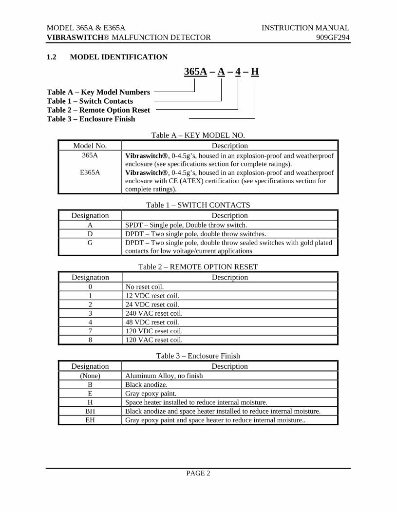
Vibraswitch®, 0-4.5g’s, housed in an explosion-proof and weatherproof enclosure (see specifications section for complete ratings). Vibraswitch®, 0-4.5g’s, housed in an explosion-proof and weatherproof enclosure with CE (ATEX) certification (see specifications section for complete ratings).
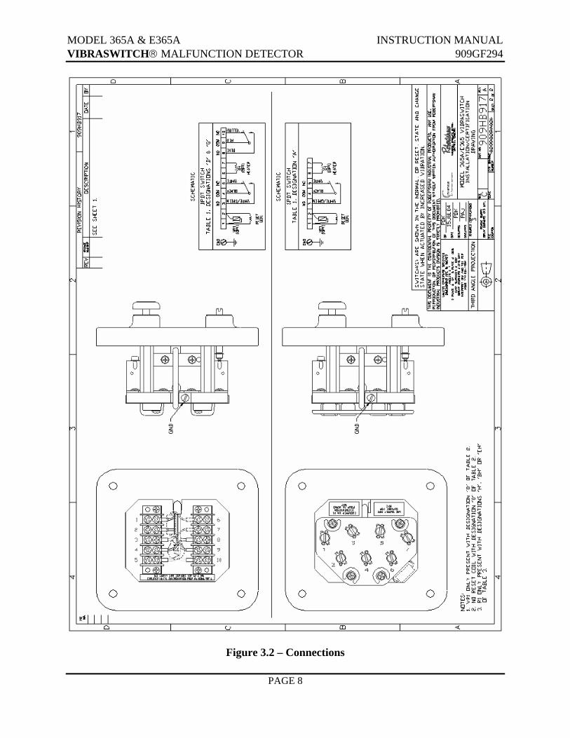
Table 1 – SWITCH CONTACTS
Designation Description A SPDT – Single pole, Double throw switch. D DPDT – Two single pole, double throw switches. G DPDT – Two single pole, double throw sealed switches with gold plated
Enclosure Classification Approved for Class I, Division 1, Group B, C, & D
Class II, Division 1, Group E, F, & G; Enclosure 4 & 4X Class I, Zone 1, AEx d IIB +H2 T6; Ex d IIB+H2 T6; IP66 ATEX EEx d IIB+H2 T6 IP66 CE 0539 II 2 G Ambient Temperature Limits -13°F to +140°F (-25°C to +60°C)
Humidity To 95% RH @ 100°F (+37.8°C), non-condensing
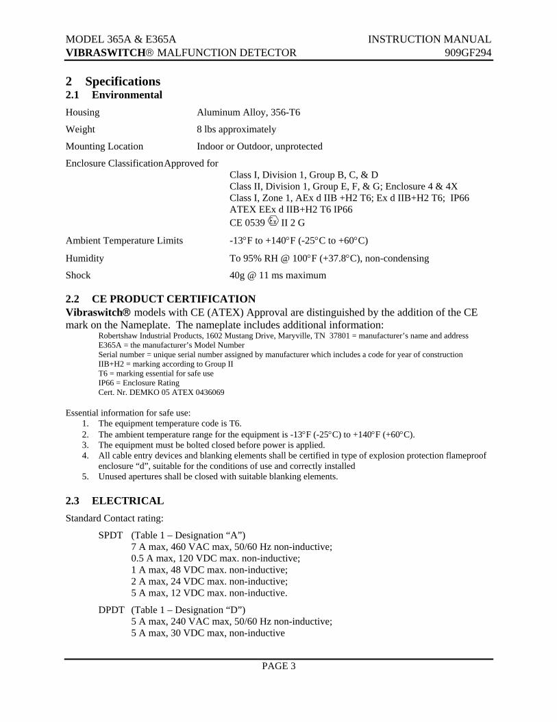
Shock 40g @ 11 ms maximum 2.2 CE PRODUCT CERTIFICATION Vibraswitch® models with CE (ATEX) Approval are distinguished by the addition of the CE mark on the Nameplate. The nameplate includes additional information: Robertshaw Industrial Products, 1602 Mustang Drive, Maryville, TN 37801 = manufacturer’s name and address E365A = the manufacturer’s Model Number Serial number = unique serial number assigned by manufacturer which includes a code for year of construction IIB+H2 = marking according to Group II T6 = marking essential for safe use IP66 = Enclosure Rating Cert. Nr. DEMKO 05 ATEX 0436069 Essential information for safe use:
1. The equipment temperature code is T6. 2. The ambient temperature range for the equipment is -13°F (-25°C) to +140°F (+60°C). 3. The equipment must be bolted closed before power is applied. 4. All cable entry devices and blanking elements shall be certified in type of explosion protection flameproof
enclosure “d”, suitable for the conditions of use and correctly installed 5. Unused apertures shall be closed with suitable blanking elements.
MODEL 365A & E365A INSTRUCTION MANUAL VIBRASWITCH® MALFUNCTION DETECTOR 909GF294
PAGE 4
Gold Contact rating:
DPDT (Table 1 – Designation “G”) 0.1 A max, 125-250 VAC, non-inductive; 0.1 A max, 30 VDC, non-inductive; 1 mA min, 24 VDC, non-inductive; 2 mA min, 12 VDC, non-inductive;
5 mA min, 6 VDC, non-inductive
Reset Coil Power: 12 VDC, 1.5 A 24 VDC, 0.5 A 48 VDC, 0.2 A 120 VDC, 0.14 A 120 VAC, 0.3 A 240 VAC, 0.3 A
Maximum Energized Time: 4 minutes
2.4 PERFORMANCE Vibration Measurement Range:
0 to 4.5g (peak) from 0 to 300 Hz (18,000 RPM) – when horizontally mounted. 0 to 3.5g (peak) from 0 to 300 Hz (18,000 RPM) – when vertically mounted.
Setpoint Range: 0 to 4.5 g
Setpoint Adjustment: Approximately 1g per turn
Accuracy: ± 5% of full range from 0 to 300 Hz (18,000 RPM)
Operating Temperature Range:
-25°C to +60°C (-13°F to +140°F)
Ambient Temperature Effects:
± 10% / 100°F (55.5°C) max
MODEL 365A & E365A INSTRUCTION MANUAL VIBRASWITCH® MALFUNCTION DETECTOR 909GF294
PAGE 5
3 INSTALLATION 3.1 GENERAL Examine the Vibraswitch® for possible shipping damages. IMPORTANT: If for any reason it is determined that the equipment should be returned to the factory, please notify the nearest Robertshaw Sales representative prior to shipment. Each unit must be properly packaged to prevent damage. Robertshaw assumes no responsibility for equipment damaged in shipment due to improper packaging.
Choose the location in accordance with good instrument practice, avoiding extremes of temperature, humidity and vibration. (See SECTION 2 – SPECIFICATIONS)
The Model 365A Vibraswitch® is UL, and cUL Certified for use in hazardous locations as indicated in section 2 -- SPECIFICATIONS. The Model E365A Vibraswitch® is UL, cUL and ATEX Certified for use in hazardous locations as indicated in section 2 -- SPECIFICATIONS.
In locations where moisture condensation within explosion proof junction boxes is a problem, a 2-watt resistor may be placed across terminals 6 and 7 inside the Vibraswitch® and wired to provide continuous heating and air circulation. (See Table 3-1 for resistance values.)
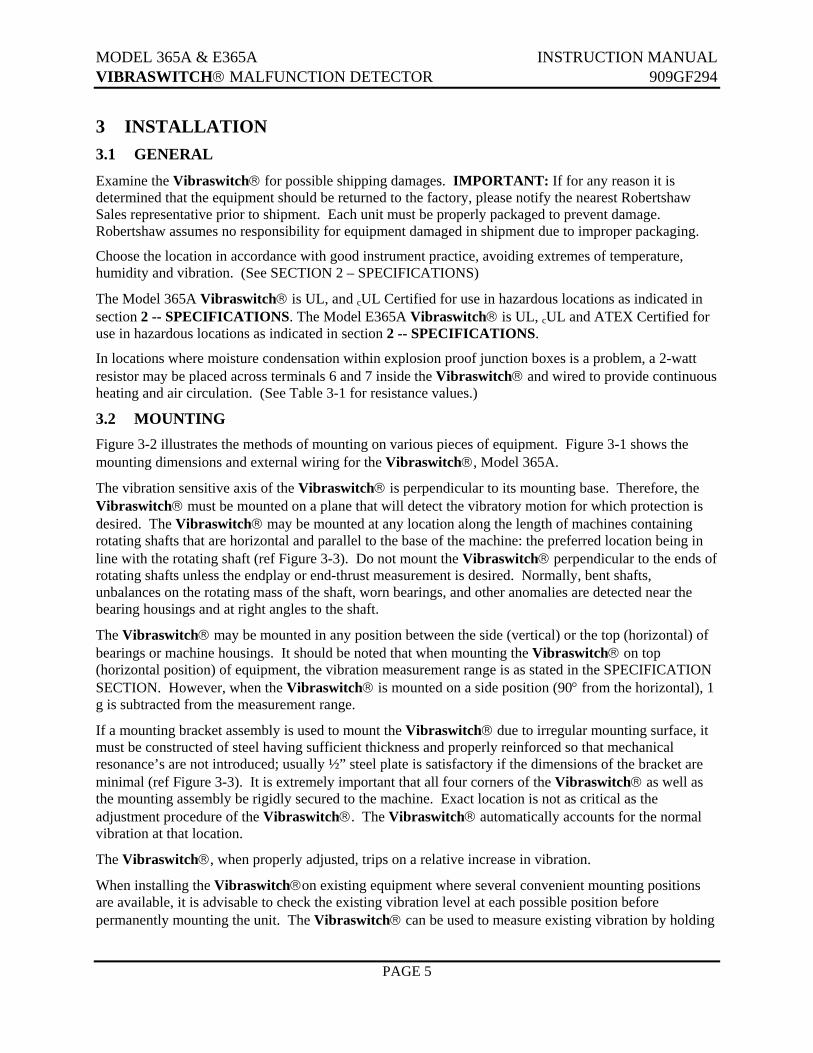
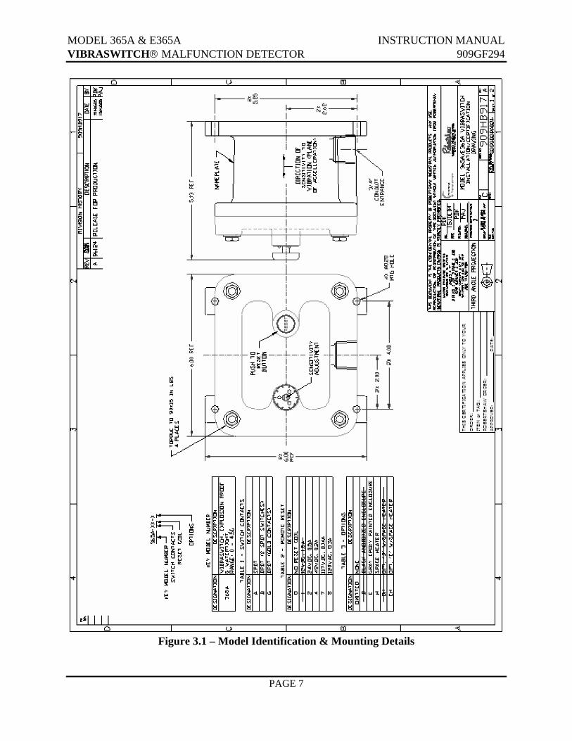
3.2 MOUNTING Figure 3-2 illustrates the methods of mounting on various pieces of equipment. Figure 3-1 shows the mounting dimensions and external wiring for the Vibraswitch®, Model 365A.
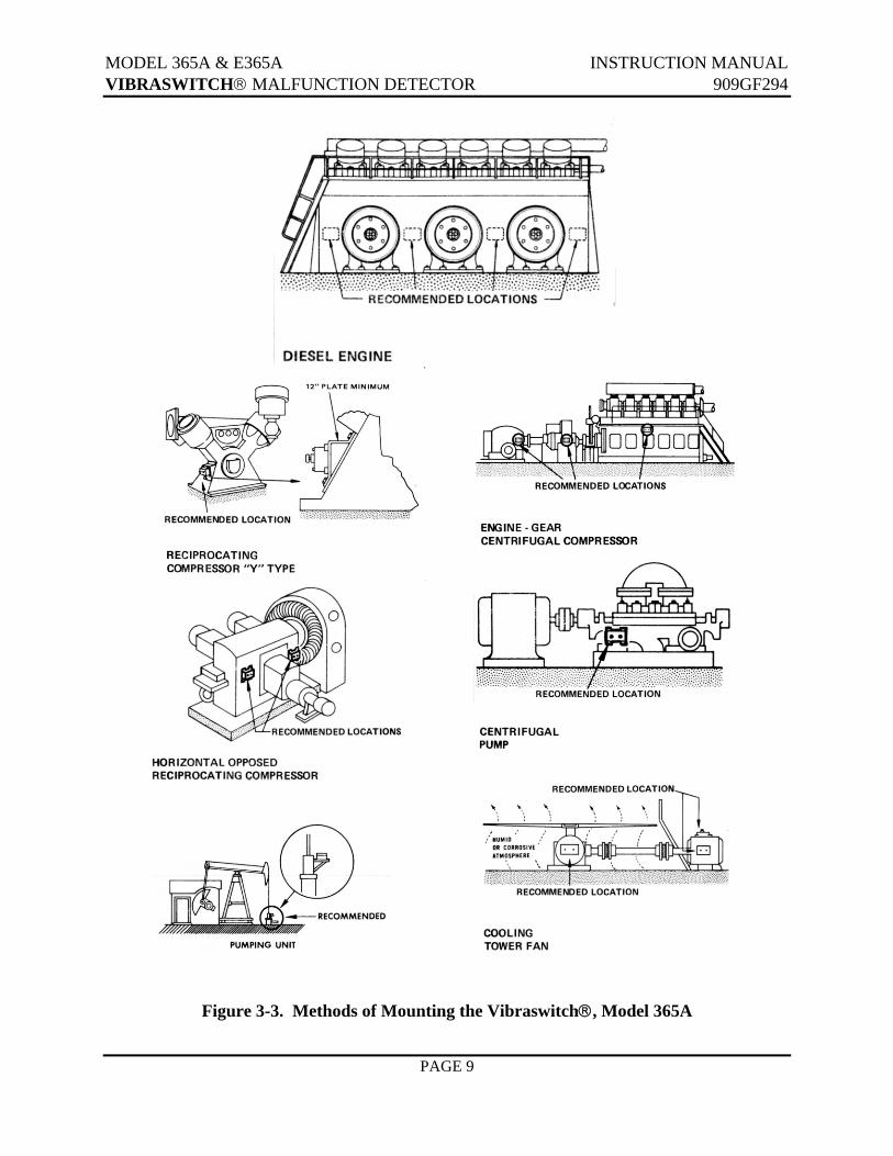
The vibration sensitive axis of the Vibraswitch® is perpendicular to its mounting base. Therefore, the Vibraswitch® must be mounted on a plane that will detect the vibratory motion for which protection is desired. The Vibraswitch® may be mounted at any location along the length of machines containing rotating shafts that are horizontal and parallel to the base of the machine: the preferred location being in line with the rotating shaft (ref Figure 3-3). Do not mount the Vibraswitch® perpendicular to the ends of rotating shafts unless the endplay or end-thrust measurement is desired. Normally, bent shafts, unbalances on the rotating mass of the shaft, worn bearings, and other anomalies are detected near the bearing housings and at right angles to the shaft.
The Vibraswitch® may be mounted in any position between the side (vertical) or the top (horizontal) of bearings or machine housings. It should be noted that when mounting the Vibraswitch® on top (horizontal position) of equipment, the vibration measurement range is as stated in the SPECIFICATION SECTION. However, when the Vibraswitch® is mounted on a side position (90° from the horizontal), 1 g is subtracted from the measurement range.
If a mounting bracket assembly is used to mount the Vibraswitch® due to irregular mounting surface, it must be constructed of steel having sufficient thickness and properly reinforced so that mechanical resonance’s are not introduced; usually ½” steel plate is satisfactory if the dimensions of the bracket are minimal (ref Figure 3-3). It is extremely important that all four corners of the Vibraswitch® as well as the mounting assembly be rigidly secured to the machine. Exact location is not as critical as the adjustment procedure of the Vibraswitch®. The Vibraswitch® automatically accounts for the normal vibration at that location.
The Vibraswitch®, when properly adjusted, trips on a relative increase in vibration.
When installing the Vibraswitch®on existing equipment where several convenient mounting positions are available, it is advisable to check the existing vibration level at each possible position before permanently mounting the unit. The Vibraswitch® can be used to measure existing vibration by holding
MODEL 365A & E365A INSTRUCTION MANUAL VIBRASWITCH® MALFUNCTION DETECTOR 909GF294
PAGE 6
or clamping it against the running machine and determining the trip point as described under “ADJUSTMENT” in this manual. Should normal vibration exceed the range of the Vibraswitch®, it is recommended that consideration be given to a Robertshaw Velocity-Acceleration Vibration Monitor, Model 566.
3.3 SPACE HEATER
In some outdoor installations, it may be necessary to install a space heater to prevent moisture condensation. A small conventional carbon 2-watt resistor should be installed across terminals 6 and 7 in the detector. It should be noted that the Vibraswitch® might be ordered from the factory with the space heater already installed. Proper values for the resistor are shown in Table 3-1.
Table 3-1. SPACE HEATER RESISTOR VALUES VOLTAGE (AC OR DC) SPACE HEATER RESISTOR (Ohms)
120/120 12,000 48 2,200 24 620 12 150
3.4 WIRING
The Vibraswitch® Model 365A & E365A is equipped with a threaded hub for ¾” conduit. When the vibration amplitude is large (ie, greater than 5 mils) it is good practice to use a short length of flexible conduit to serve as an isolator between the rigid conduit and the Vibraswitch®. Wiring into the unit should be done with #18 stranded wire, although #14 can be used where necessary. The Vibraswitch®was not designed for wiring with heavy, solid wire. However, where necessary to use a heavier wire, as in low voltage DC, a junction box near the Vibraswitch® should be used. NOTE
The instrument must be sealed at the conduit outlets with a suitable compound or “trap” to prevent infiltration of moisture laden air or
corrosive gases into the housing.
NOTE All instrument installation wiring must be done in accordance with local
codes and commonly acceptable practices.
NOTE All cable entry devices and blanking elements shall be certified in type of
explosion protection flameproof enclosure “d”, suitable for the conditions of use and correctly installed.
NOTE Unused apertures shall be closed with suitable blanking elements.
MODEL 365A & E365A INSTRUCTION MANUAL VIBRASWITCH® MALFUNCTION DETECTOR 909GF294
PAGE 7
Figure 3.1 – Model Identification & Mounting Details
MODEL 365A & E365A INSTRUCTION MANUAL VIBRASWITCH® MALFUNCTION DETECTOR 909GF294
PAGE 8
Figure 3.2 – Connections
MODEL 365A & E365A INSTRUCTION MANUAL VIBRASWITCH® MALFUNCTION DETECTOR 909GF294
PAGE 9
Figure 3-3. Methods of Mounting the Vibraswitch®, Model 365A
MODEL 365A & E365A INSTRUCTION MANUAL VIBRASWITCH® MALFUNCTION DETECTOR 909GF294
PAGE 10
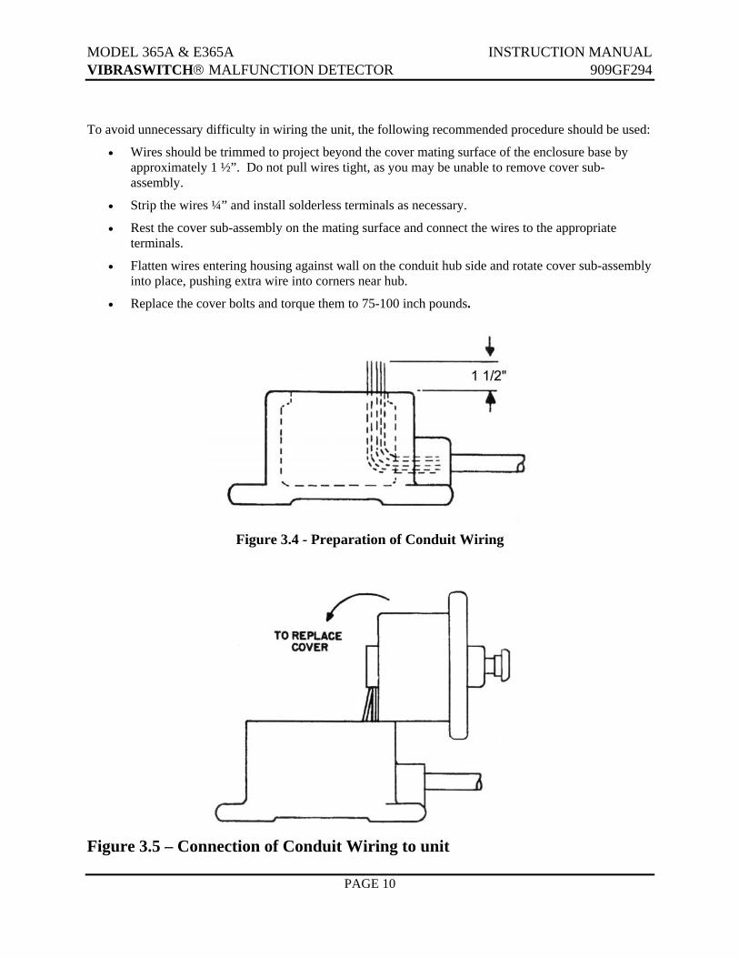
To avoid unnecessary difficulty in wiring the unit, the following recommended procedure should be used:
• Wires should be trimmed to project beyond the cover mating surface of the enclosure base by approximately 1 ½”. Do not pull wires tight, as you may be unable to remove cover sub-assembly.
• Strip the wires ¼” and install solderless terminals as necessary.
• Rest the cover sub-assembly on the mating surface and connect the wires to the appropriate terminals.
• Flatten wires entering housing against wall on the conduit hub side and rotate cover sub-assembly into place, pushing extra wire into corners near hub.
• Replace the cover bolts and torque them to 75-100 inch pounds.
Figure 3.4 - Preparation of Conduit Wiring
Figure 3.5 – Connection of Conduit Wiring to unit
MODEL 365A & E365A INSTRUCTION MANUAL VIBRASWITCH® MALFUNCTION DETECTOR 909GF294
PAGE 11
4 OPERATION 4.1 GENERAL The Model 365A & E365AVibraswitch® (Ref. Figure 4-1) is sensitive to vibration in a direction (the sensitive axis) perpendicular to its mounting base. It contains an acceleration sensitive mechanism, which also functions as a “mechanical amplifier”, to activate a snap action switch when the selected level of vibration is exceeded and the detecting mechanism “trips”.
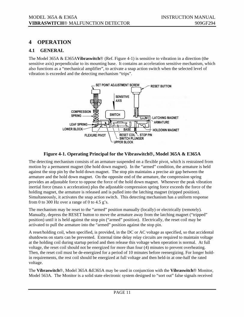
Figure 4-1. Operating Principal for the Vibraswitch®, Model 365A & E365A
The detecting mechanism consists of an armature suspended on a flexible pivot, which is restrained from motion by a permanent magnet (the hold down magnet). In the “armed” condition, the armature is held against the stop pin by the hold down magnet. The stop pin maintains a precise air gap between the armature and the hold down magnet. On the opposite end of the armature, the compression spring provides an adjustable force to oppose the force of the hold down magnet. Whenever the peak vibration inertial force (mass x acceleration) plus the adjustable compression spring force exceeds the force of the holding magnet, the armature is released and is pulled into the latching magnet (tripped position). Simultaneously, it activates the snap action switch. This detecting mechanism has a uniform response from 0 to 300 Hz over a range of 0 to 4.5 g’s.
The mechanism may be reset to the “armed” position manually (locally) or electrically (remotely). Manually, depress the RESET button to move the armature away from the latching magnet (“tripped” position) until it is held against the stop pin (“armed” position). Electrically, the reset coil may be activated to pull the armature into the “armed” position against the stop pin.
A reset/holding coil, when specified, is provided, in the DC or AC voltage as specified, so that accidental shutdowns on starts can be prevented. External time delay relay circuits are required to maintain voltage at the holding coil during startup period and then release this voltage when operation is normal. At full voltage, the reset coil should not be energized for more than four (4) minutes to prevent overheating. Then, the reset coil must be de-energized for a period of 10 minutes before reenergizing. For longer hold-in requirements, the rest coil should be energized at full voltage and then held-in at one-half the rated voltage.
The Vibraswitch®, Model 365A &E365A may be used in conjunction with the Vibraswitch® Monitor, Model 563A. The Monitor is a solid state electronic system designed to “sort out” false signals received
MODEL 365A & E365A INSTRUCTION MANUAL VIBRASWITCH® MALFUNCTION DETECTOR 909GF294
PAGE 12
by the Vibraswitch® so that Alarm and/or Shutdown of operating machine will not result from false, transient disturbances. Examples of transient disturbances are the closing of pipeline check valves on pumping applications, the start up of additional pumps on a line, and the initial start up of various operating machines. These disturbances may cause the Vibraswitch® to “trip” if the vibratory shock level is in excess of its setpoint.
The purpose of the Vibraswitch® Monitor is to “supervise” and “sort out” the transient disturbances so that Alarm or Shutdown is not falsely imposed on the machine being monitored, but any continuous vibration level, which exceeds the Setpoint of the Vibraswitch®, will cause Alarm and/or Shutdown.
4.2 ADJUSTMENTS OF OPERATING SETPOINT The operating setpoint for the Vibraswitch® varies with the type of machine and its location (measurement point) on the machine. The setpoint adjustments suggested in this manual are for machines, which are functioning in a “good” or “normal” condition. This method follows the concept of vibration tolerance for the machine and in this case is dependant upon an individual who is experienced in the operation of the machine vibration as “normal”, “fair”, “slightly rough”, etc. These various degrees of machine vibration are therefore, based on the individual’s physical perception between normal and abnormal roughness while the machine is operating.
This method can lead to differences in the classification of the degree of vibration between individual observers. Robertshaw believes that if the machine is operating satisfactorily, as previously defined, and the acceleration sensed by the Vibraswitch® is within certain limits, the settings made as outlined in the following instructions will offer protection of the machine and prevent catastrophic failure.
For example, assume that a relatively new machine, which, to an experienced observer, is operating as “smooth” or “good” regarding vibration and the Vibraswitch,® measures this acceleration level to be 0.25 g above its static condition (zero). Experience suggests that an acceptable setting for alarm conditions would be a minimum of twice this value, or 0.5 g. It is acknowledged that such a definition of upper vibration limit (alarm condition) on the machine may not adequately define the upper tolerance limit of the machine before major repairs are required or excessive machine damage occurs. It does, however define a limit that has proven to be “safe”. As the user becomes more experienced using the Vibraswitch® as a monitoring device, his experience may indicate that a higher setpoint is acceptable on the particular machine.
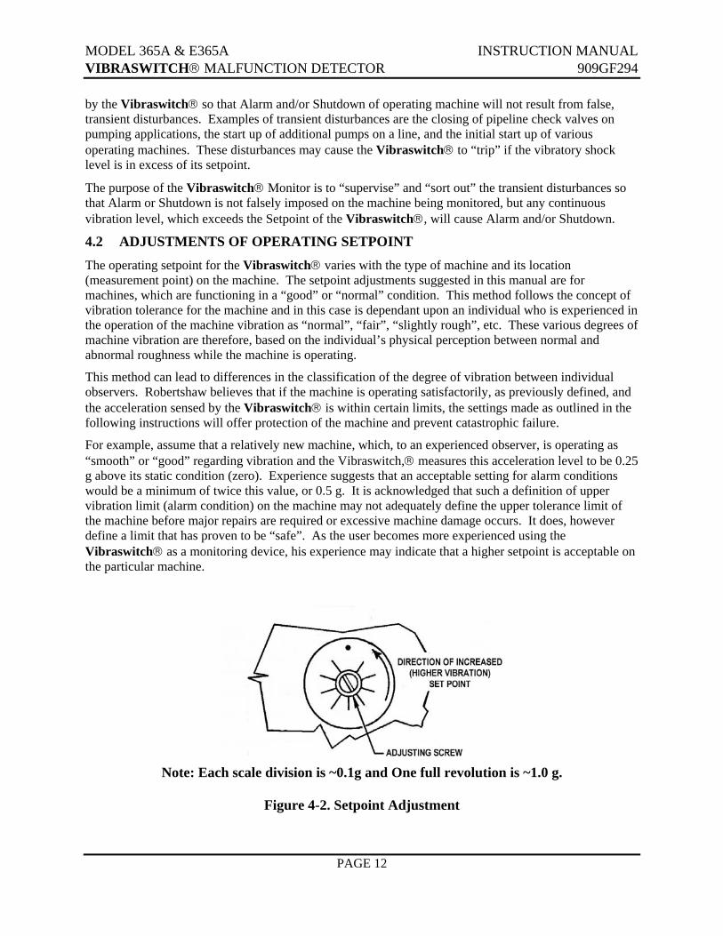
Note: Each scale division is ~0.1g and One full revolution is ~1.0 g.
Figure 4-2. Setpoint Adjustment
MODEL 365A & E365A INSTRUCTION MANUAL VIBRASWITCH® MALFUNCTION DETECTOR 909GF294
PAGE 13
The Model 365A & E365A Vibraswitch® is adjusted by a simple three-step procedure (Ref., Figure 4-2).
1. Zero Vibration Level Measurement
With the equipment on which the Vibraswitch® is mounted not operating, back off the SETPOINT adjustment screw counterclockwise (CCW) two (2) turns and press the RESET button. Then turn the SETPOINT adjustment screw slowly clockwise until actuation occurs (the armature assembly is against the latch magnet, Figure 4-1). This is the zero vibration point, or actuating point, with the machine not operating. A mark should be made with a pencil or other convenient means to permanently record this “zero” vibration point. Subsequent measurements are made relative to this point.
2. Normal g-Level Measurements
With the machine (equipment) operating, back off the Setpoint adjusting screw one turn CCW and reset. If it will not reset, back off the Setpoint adjusting screw two turns CCW. Again turn the Setpoint adjusting screw slowly clockwise until actuation occurs. Mark this position with a pencil or other convenient means. The difference between the two actuating points in Steps 1 and 2 is the normal g-level of the operating machine, in scale divisions. One scale division is ~0.1 g; one full revolution is ~1.0 g.
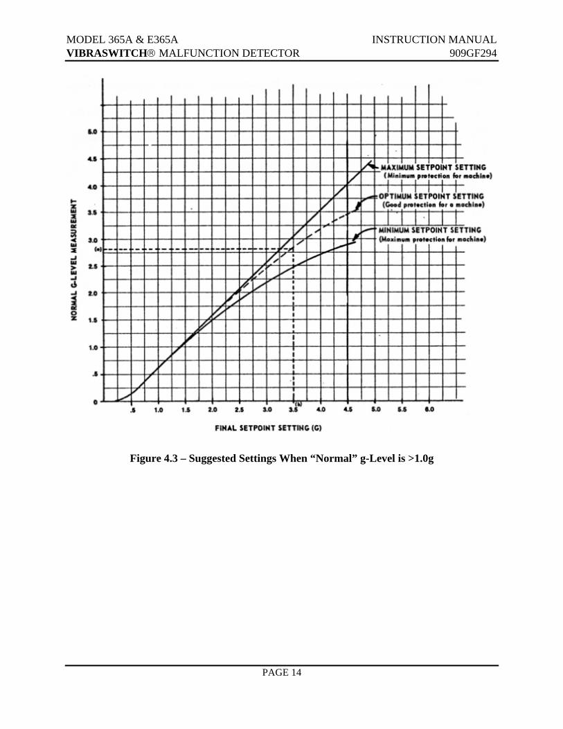
3. Final Setpoint Adjustment If the “normal” g-level is less than 1.0 g above the zero level, rotate the Setpoint adjusting screw CCW ~0.5 g (five graduations) from the point where actuation occurs in Step 2 above. If the “normal” g-level is greater than 1.0 g refer to figure 4-3 for the proper Final Setpoint setting with respect to the “normal g-level vibration point” obtained in Step 2.
NOTE
In preceding adjustments, actuation can be heard as an audible click. In very noisy surroundings, it may be necessary to use an ohmmeter or wire the Vibraswitch to the control circuit to tell when actuation occurs.
MODEL 365A & E365A INSTRUCTION MANUAL VIBRASWITCH® MALFUNCTION DETECTOR 909GF294
PAGE 14
Figure 4.3 – Suggested Settings When “Normal” g-Level is >1.0g
MODEL 365A & E365A INSTRUCTION MANUAL VIBRASWITCH® MALFUNCTION DETECTOR 909GF294
PAGE 15
5. MAINTENANCE The Vibraswitch® does not normally require any maintenance or repair; however, listed below are some of the possible malfunctions that may occur and their recommended solutions.
5.1 FUNCTIONAL TEST (Ref. Figure 4-1)
1. With the Vibraswitch® cover sub-assembly removed, place the Vibraswitch® on a table with its mounting surface horizontal.
2. Press RESET button. If switch does not “reset” (armature latched on stop pin), turn set point adjustment screw CCW until switch can be manually reset.
3. Slowly turn SETPOINT adjustment screw CW until switch trips. This is the Zero trip point or the amount of spring tension required to overcome the 1 g force exerted by the earth’s gravitational pull.
4. Note SETPOINT adjustment. One complete turn equals approximately 1 g. Set point scale is marked in 0.1 g increments. Turn the set point adjusting screw 1 complete turn CCW. This is a 1 g setting above the earth’s gravitational pull.
5. Manually reset the switch (press RESET button).
6. With the RESET button to your right and the SETPOINT adjustment screw to your left, slowly rotate the Vibraswitch® toward you 90°. The switch will trip when the mounting surface is in a vertical plane and the earth’s gravitational pull is not aiding the lower magnet to hold the armature against the stop pin.
5.2 TROUBLESHOOTING There are several possible failure mode for the Vibraswitch® and the following paragraphs provide information to diagnose the possible causes:
5.2.1 Vibraswitch® Will Not Reset 1. Dirt and/or metal chips on magnets
Clean magnets
2. Broken leaf spring (Refer to Figure 4-1). Return Vibraswitch® to the factory for repair.
3. Open reset coil Check for continuity and proper coil resistance (refer to Table 5-1). If reading is not acceptable return Vibraswitch® to the factory for repair.
Check for continuity only. (Diode prevents actual resistance reading)
MODEL 365A & E365A INSTRUCTION MANUAL VIBRASWITCH® MALFUNCTION DETECTOR 909GF294
PAGE 16
5.2.2 Unable to Adjust Set point Setting to Obtain Trip An improper air gap exists between hold down (lower) magnet and armature. Return the Vibraswitch® to the factory for repair.
5.2.3 Switch Does Not Actuate Defective Switch – verify by manually moving the Armature to the latched (tripped) position and listen for an audible click of the switch. Verify contact change-of-state by performing a continuity check. If the switch does not pass either of the tests above, return the Vibraswitch® to the factory for repair.