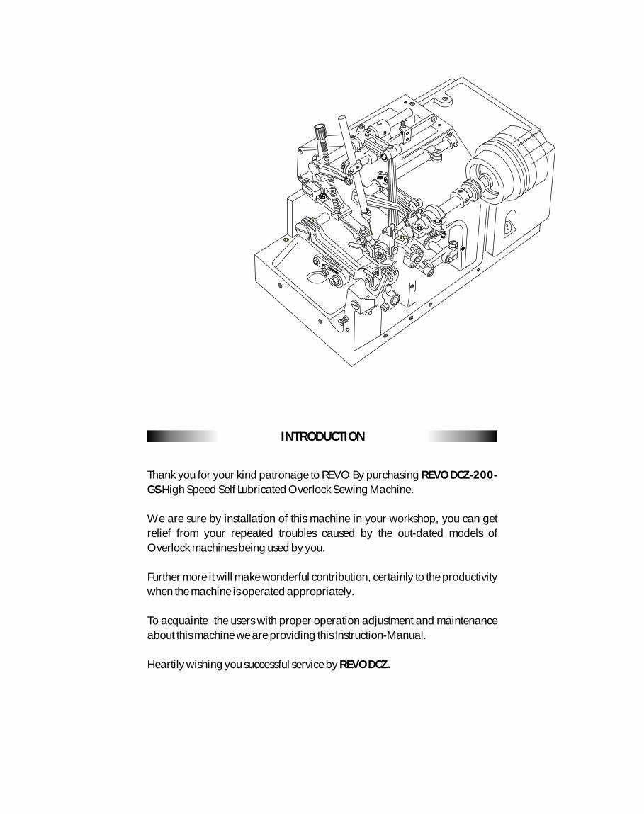
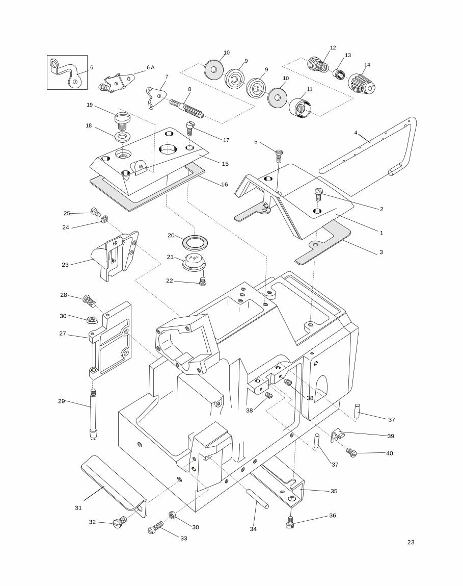
Thank you for your kind patronage to REVO By purchasing REVO DCZ-200- GS High Speed Self Lubricated Overlock Sewing Machine. We are sure by installation of this machine in your workshop, you can get relief from your repeated troubles caused by the out-dated models of Overlock machines being used by you. Further more it will make wonderful contribution, certainly to the productivity when the machine is operated appropriately. To acquainte the users with proper operation adjustment and maintenance about this machine we are providing this Instruction-Manual. Heartily wishing you successful service by REVO DCZ. INTRODUCTION
Transcript
Thank you for your kind patronage to REVO By purchasing REVO DCZ-200-
GS High Speed Self Lubricated Overlock Sewing Machine.
We are sure by installation of this machine in your workshop, you can get
relief from your repeated troubles caused by the out-dated models of
Overlock machines being used by you.
Further more it will make wonderful contribution, certainly to the productivity
when the machine is operated appropriately.
To acquainte the users with proper operation adjustment and maintenance
about this machine we are providing this Instruction-Manual.
Heartily wishing you successful service by REVO DCZ.
INTRODUCTION
SPECIFICATION
Name : High Speed Overlocked Stitch Sewing Machine
Dimensions : 350 x 225 x 285 mm.
Weight : 21 Kgs
Construction : Dust-Proof, Oil-tight, Enclosed completely.
Stitch type : Overedge seaming
Sewing Speed : upto 6,500 s.p.m.
Stitches per inch : 6-20 stitches per inch, 7- 23.5 stitches per 30mm
Use : Overedge Seaming, Blind Hemming and other uses on general or knitted materials.
Width of Overedge Seam : 3 - 4 mm, Standard and 2 - 8 mm is available by exchange of necessary Gauge Parts.
Stroke of Needle : 25 mm.
Needles : DC x 1 size 9 to 18
Adjusting of Feeding : Exchange of Eccentrics.
Knives for Fabric Cutting : Lower Knife - Made of Special Steel Flat type. Upper Knife - Made of Super Hard Alloy.
Lubrication : Force Feeding by gear pump and pressure regulating valve, and Splashed Oil is also
utilized.
Lubricant : Use H.P.'s TURBINOL-46, CASTROL's PERFECTO T-46 or any equipment Lubricant.
Keep Oil upto Maximum Level marked in the oil Indicator.
Change the entire Oil after Three Months or 1000 working hours which may be achieved
earlier.
Capacity of Reservoir : ONE LITRE
INSTALLATION
Fix Supporting Board to the Table by Bolts and Nuts, on which the Rubber Cushion Holder Plate shall be fixed by Wood
Screws. $ Rubber Cushions must be put exactly into each horrow on the plate when settiing machine.
-
Machine Table
Supporting Board
-- Fixing -- -- Fitting of Belt Cover--
-- Dimensions for Semi-submerged Installation --
A B
C
230
106
60
20 10
45 35
135
40 20
200
175
214 100
10
20
70
260
10
D D
55
280
365
Operator
200
105
4-15
16
4-7.9
Section D-D
1
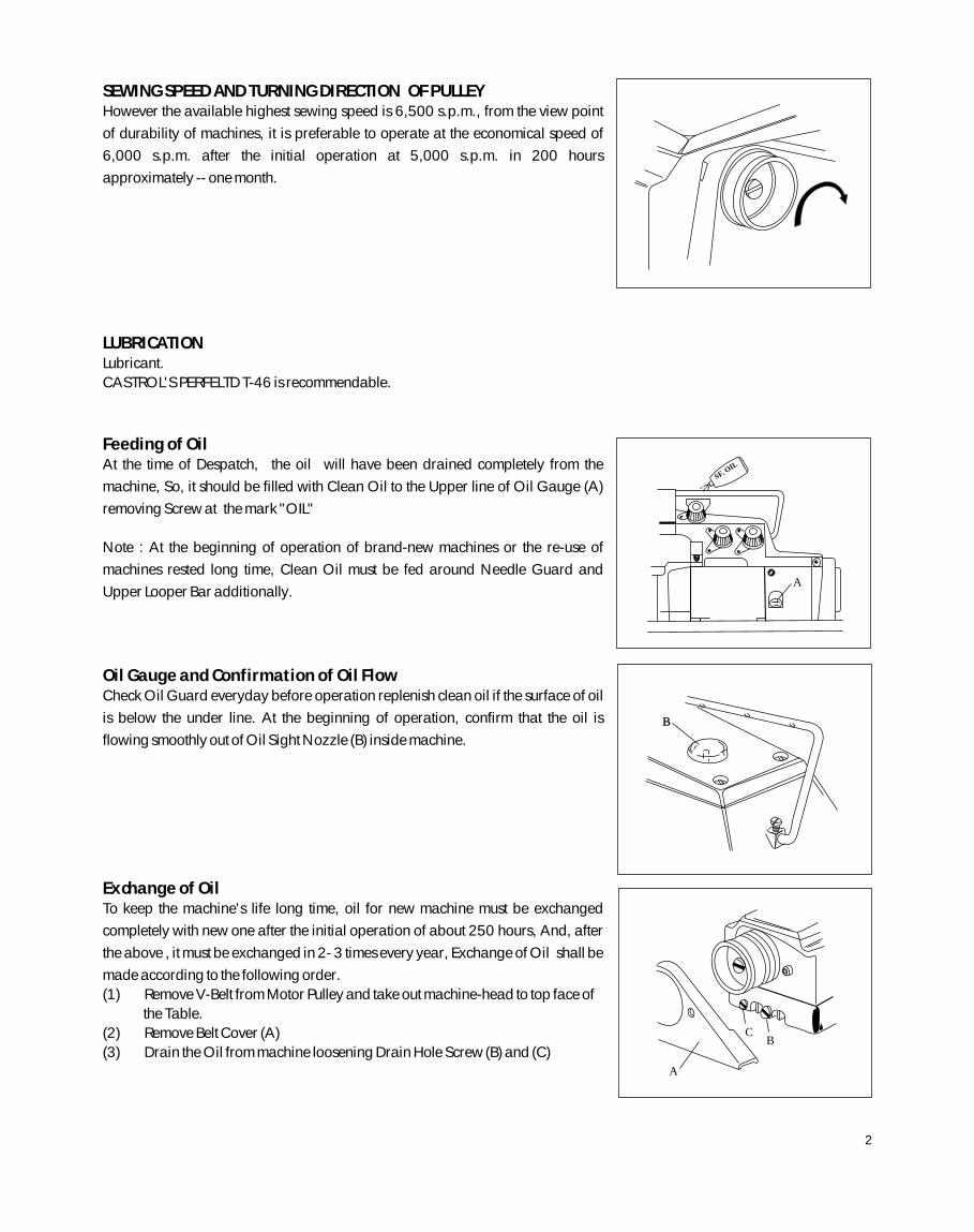
SEWING SPEED AND TURNING DIRECTION OF PULLEYHowever the available highest sewing speed is 6,500 s.p.m., from the view point
of durability of machines, it is preferable to operate at the economical speed of
6,000 s.p.m. after the initial operation at 5,000 s.p.m. in 200 hours
approximately -- one month.
LUBRICATIONLubricant.
CASTROL'S PERFELTD T-46 is recommendable.
Feeding of OilAt the time of Despatch, the oil will have been drained completely from the
machine, So, it should be filled with Clean Oil to the Upper line of Oil Gauge (A)
removing Screw at the mark "OIL"
Note : At the beginning of operation of brand-new machines or the re-use of
machines rested long time, Clean Oil must be fed around Needle Guard and
Upper Looper Bar additionally.
Oil Gauge and Confirmation of Oil FlowCheck Oil Guard everyday before operation replenish clean oil if the surface of oil
is below the under line. At the beginning of operation, confirm that the oil is
flowing smoothly out of Oil Sight Nozzle (B) inside machine.
Exchange of OilTo keep the machine's life long time, oil for new machine must be exchanged
completely with new one after the initial operation of about 250 hours, And, after
the above , it must be exchanged in 2- 3 times every year, Exchange of Oil shall be
made according to the following order.
(1) Remove V-Belt from Motor Pulley and take out machine-head to top face of
the Table.
(2) Remove Belt Cover (A)
(3) Drain the Oil from machine loosening Drain Hole Screw (B) and (C)
A
SF. OIL
B
A
B C
2
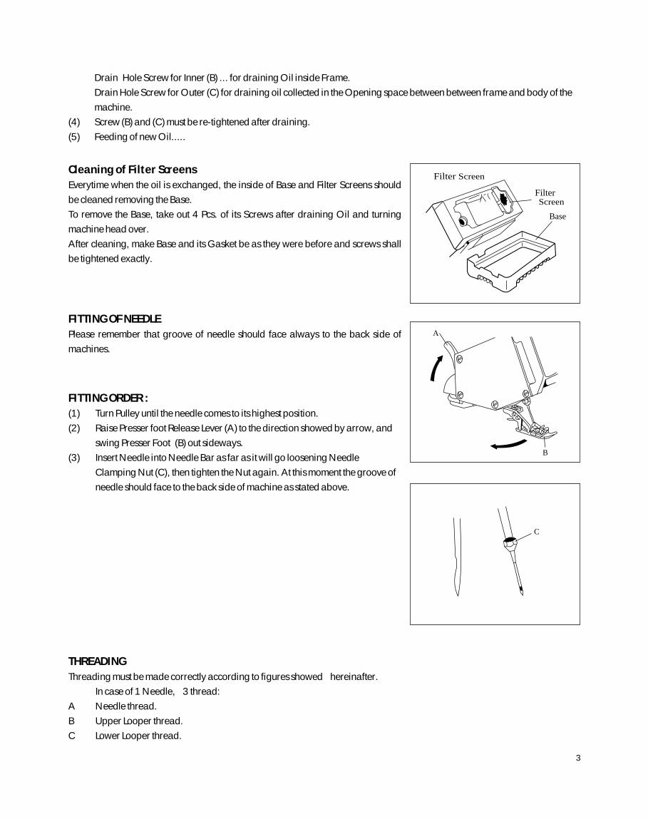
Cleaning of Filter Screens
Everytime when the oil is exchanged, the inside of Base and Filter Screens should
be cleaned removing the Base.
To remove the Base, take out 4 Pcs. of its Screws after draining Oil and turning
machine head over.
After cleaning, make Base and its Gasket be as they were before and screws shall
be tightened exactly.
FITTING OF NEEDLE
Please remember that groove of needle should face always to the back side of
machines.
FITTING ORDER :
(1) Turn Pulley until the needle comes to its highest position.
(2) Raise Presser foot Release Lever (A) to the direction showed by arrow, and
swing Presser Foot (B) out sideways.
(3) Insert Needle into Needle Bar as far as it will go loosening Needle
Clamping Nut (C), then tighten the Nut again. At this moment the groove of
needle should face to the back side of machine as stated above.
THREADING
Threading must be made correctly according to figures showed hereinafter.
In case of 1 Needle, 3 thread:
A Needle thread.
B Upper Looper thread.
C Lower Looper thread.
Drain Hole Screw for Inner (B) ... for draining Oil inside Frame.
Drain Hole Screw for Outer (C) for draining oil collected in the Opening space between between frame and body of the
machine.
(4) Screw (B) and (C) must be re-tightened after draining.
(5) Feeding of new Oil.....
C
A
B
Filter Screen
Base
Filter Screen
3
Position of Needle Thread Eyelet must be changed in case of blind hemming.
Refer to "Needle thread Tension" on page 9 please.
In case of 1 Needle 2 thread with spreader
A Needle Thread
B Lower Looper thread.
THREAD TENSION
Tension of thread should be adjusted as loosely as possible unless the good balance is lost in the seaming.
Stronger tension beyond necessity may cause the thread-breakage or skip-stitching.
Note: Refer to items regarding to the thread tension in "Proper Adjustments" on page 9 please.
Pressure of Presser Foot
The pressure of Presser Foot should be adjusted most weakly so far as presser Foot can act properly.
However the uniformity in the feeding and seaming will be lacked if the pressure is weak excessively.
The pressure shall be strengthened when turning Adjusting Screw (C) to the direction (A) and weakened turning to (B) to
the contrary.
Pressure of Presser Foot
The pressure of Presser Foot should be adjusted most weakly so far as presser Foot
can act properly.
However the uniformity in the feeding and seaming will be lacked if the pressure is
weak excessively.
The pressure shall be strengthened when turning Adjusting Screw (C) to the
direction (A) and weakened turning to (B) to the contrary.
A
B
C
(for Blind-Hemming Stitch) A
B C
- - - - (for Wooly Tread)
4
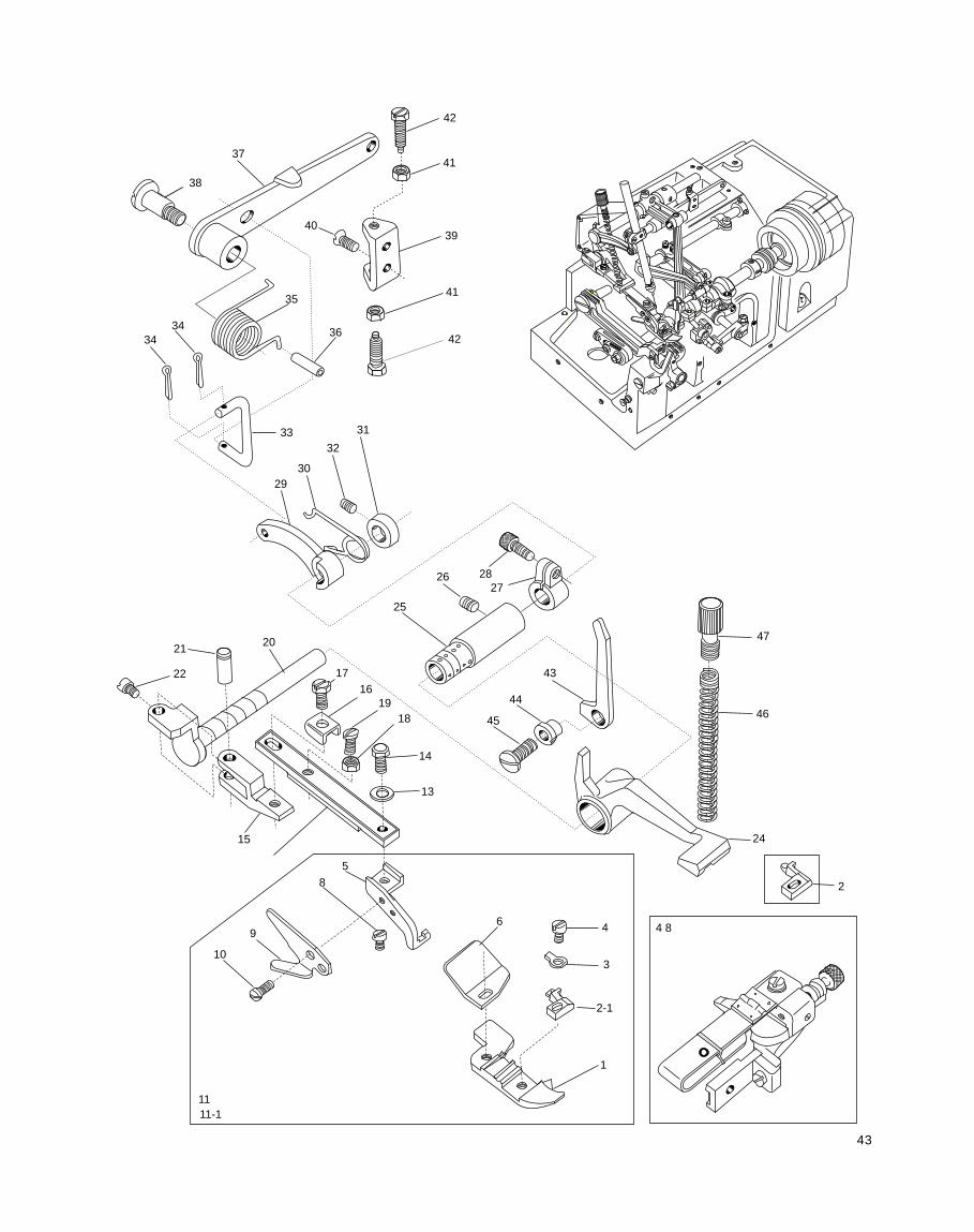
ADJUSTING OF FOOT LIFTER LEVER
Adjust Pressure Foot to Start to lift from the top face of stitch Plate turning
Adjusting Screw (E) when the Foot Lifter Lever (F) is lowered in 3 mm from the
end of Adjusting Screw (E) for Foot Lifter Lever Stopper (D). When Presser Foot
is raised to its highest position, adjust the bottom face of it to be 4mm. from top
face of Stitch Plate.
At this moment Loosen Nut (I) and turn Stop Screw for Presser Foot (H) then
adjust the Screw to touch with Arm of the machine.
ADJUSTING OF WIDTH OF OVEREDGE SEAM
To widen the width;
Loosen Screw (A) for upper Knife Holder and move the Holder to the
Direction (X) According to the necessity and tighten Screw (A) again.
Subsequently loosen Screw (B) for Lower Knife Holder. Then Lower Knife
Holder will move to the direction (X) by pressure of the spring inside,
consequently Lower Knife will adhere closely to Upper Knife (D) with suitable
strength. And, tighten Screw (B) again.]
To narrow the width
Loosen Screw (B) for Lower Knife Holder and Move the Holder to the
direction (Y) according to the necessity and tighten Screw (B) softly.
Subsequently, loosen Screw (B) for Lower Knife again and made Lower Knife
(C) adhere closely to Upper Knife (D) by the pressure of spring. Then,
retighten Screw (B).
Note : For adjusting width of the overedge seam, make the blade of Upper
Knife be higher than if of Lower Knife in 0 - 1 mm.
Sharpness of Knives
Check the sharpness of knives turning Pulley manually with a thread put
between Upper and Lower Knives, after adjusting the seam of overedge
seam.
Note : When it may be necessary to sharpen knives please refer to
"Sharpening of knives for Fabric Cutting " on Page 14.
(1)
(2)
(3)
0 ~ 1mm
I
E
D
G F
H
3mm
Thread
A
B
C
Y
XD
5
Main Feed Driving Eccentric (G) can be exchanged by the same manner stated as above, after removal of Nut (E) and (H)
Differential Feed Bar Driving Connector (L)
In case of exchange of Eccentrics, from which dust and rubbish should be removed washing, by oil. And, assemble them
making their stepped part face outside.
When Eccentric is smaller number than the one of "G" side is used at (C) side, the seam to be obtained will have a touch of
loose.
ADJUSTING OF STITCH LENGTH
By the exchange of Feed Driving Eccentrics, stitch length is adjusted, Each
Eccentric has a stamp showing Stitch numbers per inch. (25.4 mm) However,
please pay your attention to the fact that there will be difference in some measure
owing to kind or thickness of fabrics and ratio of differential feeding.
The illustration shows the view of machine set with Feed driving Eccentrics.
The Stitch Length shall be changed opening Cloth Plate (Upper) (A) and Feed
Mechanism Cover (B).
The illustration shows the condition removed Eccentrics and also Socket Wrench
and Eccentric Extractor. To Exchange Differential Feed Driving Eccentric only.
Remove Nut "E" by Socket Wrench (D)
Remove the Eccentric by Extractor (F) Screwed into its hole.
After, put Eccentric at need, and tighten Nut "E" As before.
A
B
D F
H
E C
L
G
6
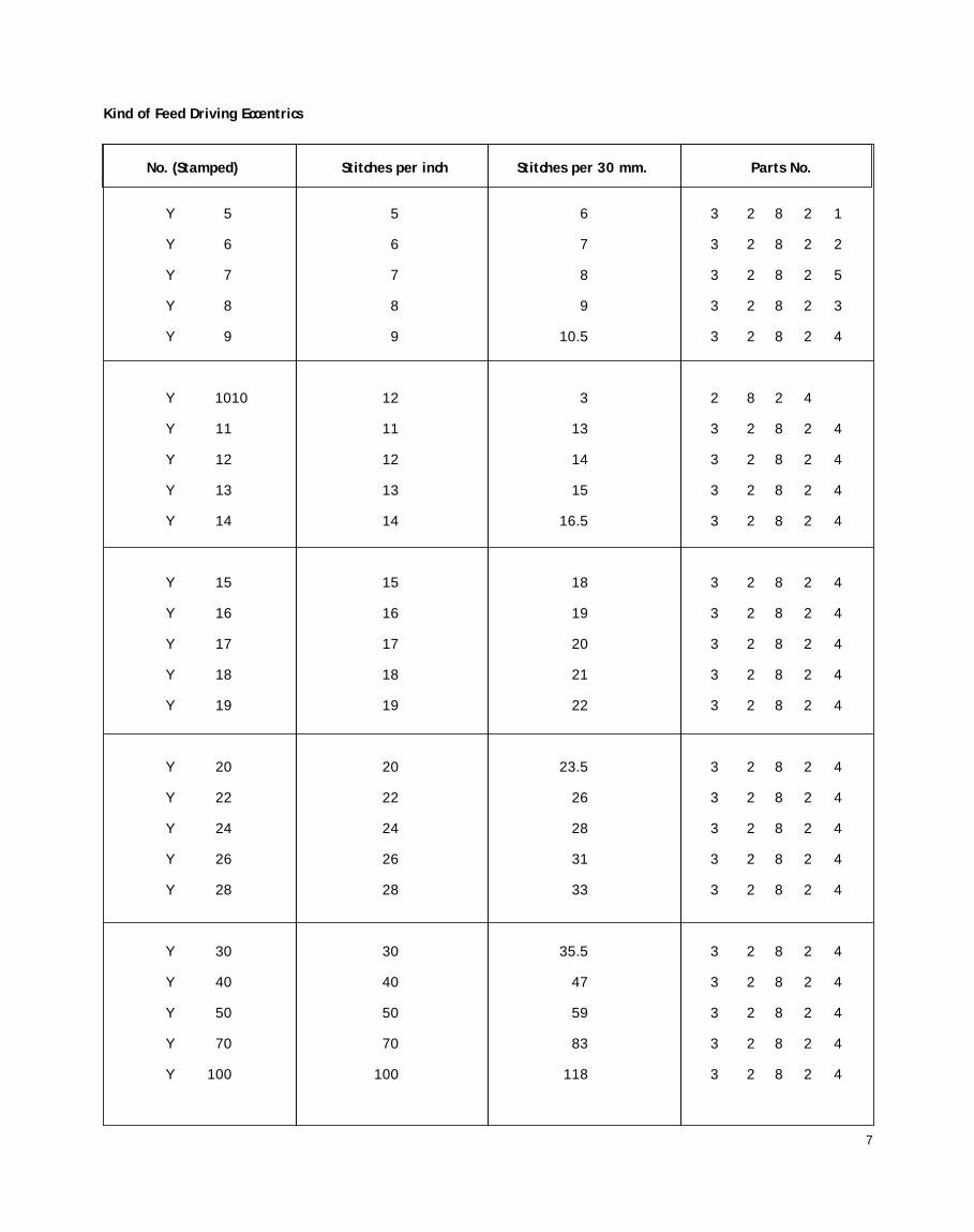
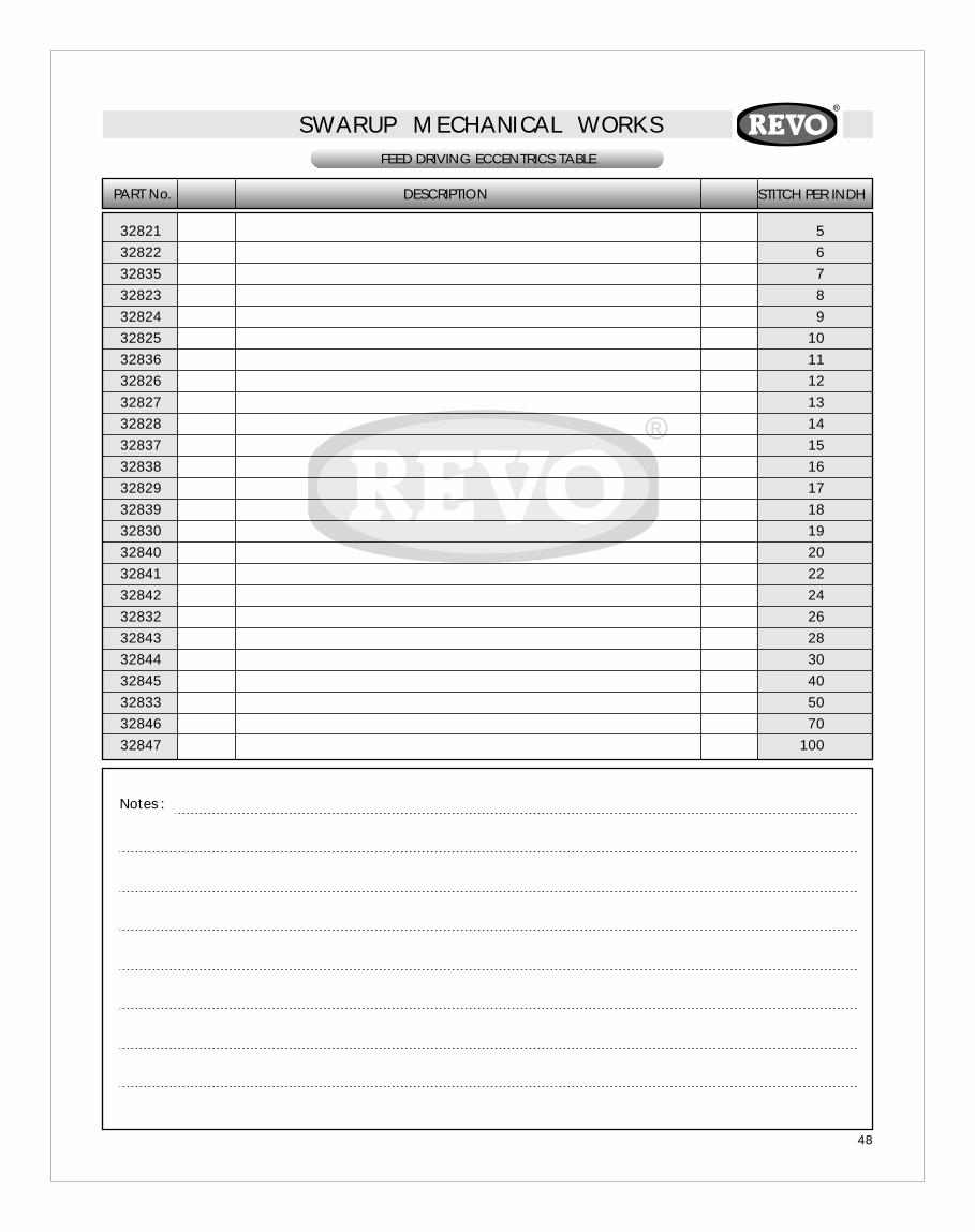
Y 5 5 6 3 2 8 2 1
Y 6 6 7 3 2 8 2 2
Y 7 7 8 3 2 8 2 5
Y 8 8 9 3 2 8 2 3
Y 9 9 10.5 3 2 8 2 4
Y 1010 12 3 2 8 2 4
Y 11 11 13 3 2 8 2 4
Y 12 12 14 3 2 8 2 4
Y 13 13 15 3 2 8 2 4
Y 14 14 16.5 3 2 8 2 4
Y 15 15 18 3 2 8 2 4
Y 16 16 19 3 2 8 2 4
Y 17 17 20 3 2 8 2 4
Y 18 18 21 3 2 8 2 4
Y 19 19 22 3 2 8 2 4
Y 20 20 23.5 3 2 8 2 4
Y 22 22 26 3 2 8 2 4
Y 24 24 28 3 2 8 2 4
Y 26 26 31 3 2 8 2 4
Y 28 28 33 3 2 8 2 4
Y 30 30 35.5 3 2 8 2 4
Y 40 40 47 3 2 8 2 4
Y 50 50 59 3 2 8 2 4
Y 70 70 83 3 2 8 2 4
Y 100 100 118 3 2 8 2 4
Kind of Feed Driving Eccentrics
No. (Stamped) Stitches per inch Stitches per 30 mm. Parts No.
7
PROPER ADJUSTMENT
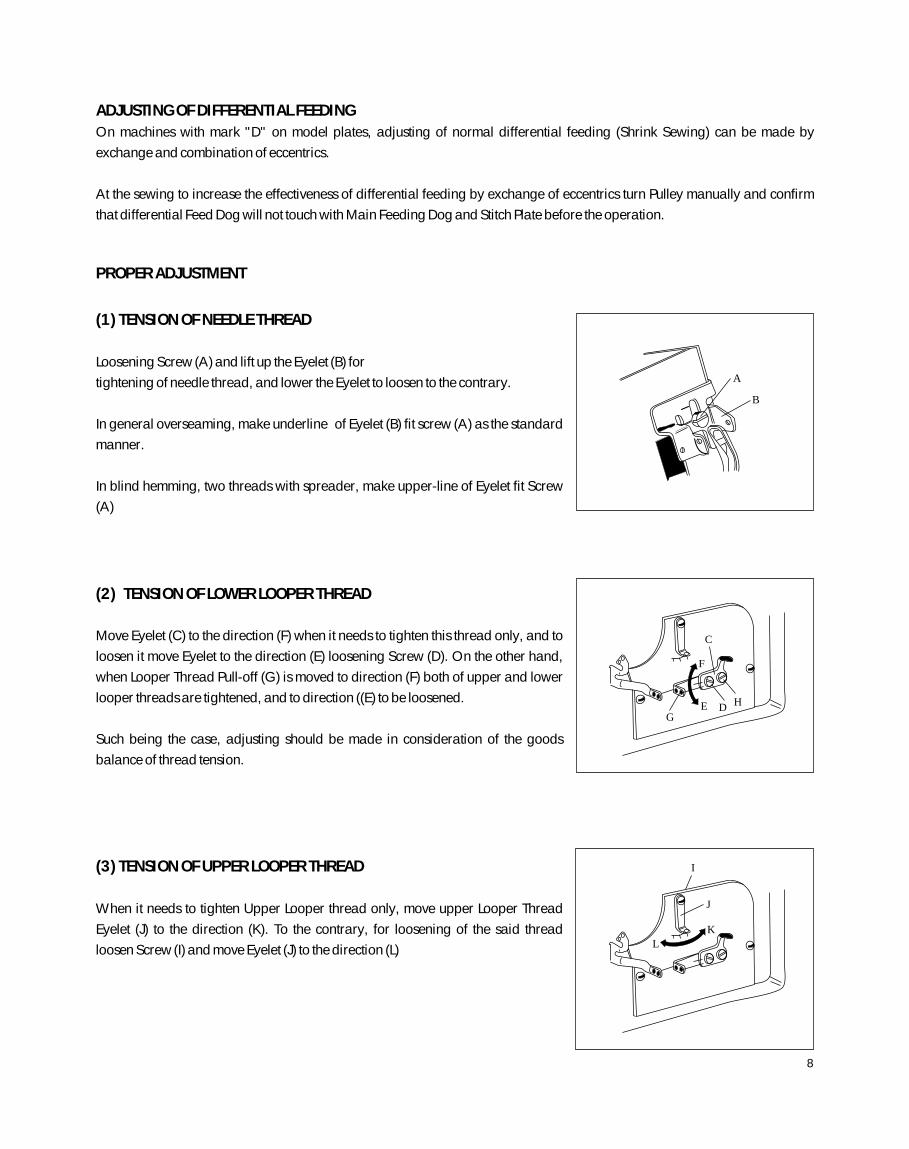
(1) TENSION OF NEEDLE THREAD
Loosening Screw (A) and lift up the Eyelet (B) for
tightening of needle thread, and lower the Eyelet to loosen to the contrary.
In general overseaming, make underline of Eyelet (B) fit screw (A) as the standard
manner.
In blind hemming, two threads with spreader, make upper-line of Eyelet fit Screw
(A)
(2) TENSION OF LOWER LOOPER THREAD
Move Eyelet (C) to the direction (F) when it needs to tighten this thread only, and to
loosen it move Eyelet to the direction (E) loosening Screw (D). On the other hand,
when Looper Thread Pull-off (G) is moved to direction (F) both of upper and lower
looper threads are tightened, and to direction ((E) to be loosened.
Such being the case, adjusting should be made in consideration of the goods
balance of thread tension.
(3) TENSION OF UPPER LOOPER THREAD
When it needs to tighten Upper Looper thread only, move upper Looper Thread
Eyelet (J) to the direction (K). To the contrary, for loosening of the said thread
loosen Screw (I) and move Eyelet (J) to the direction (L)
ADJUSTING OF DIFFERENTIAL FEEDING
On machines with mark "D" on model plates, adjusting of normal differential feeding (Shrink Sewing) can be made by
exchange and combination of eccentrics.
At the sewing to increase the effectiveness of differential feeding by exchange of eccentrics turn Pulley manually and confirm
that differential Feed Dog will not touch with Main Feeding Dog and Stitch Plate before the operation.
A
B
C
F
G E D H
J
K
L
I
8
When wooly thread is used:-
In case such thread which has a plenty elasticity is used, threading of Upper Looper
Thread should be changed according to dotted line on the illustration (Right)
Note : When it is returned to of ordinary thread after the sewing of wooly thread,
donot, forget that the threading must be changed as it was.
(4) HEIGHT OF NEEDLE
When the Needle reaches to its highest position, there should be the distance of
9.5 to 10.0mm between needle point and top face of Stitch plate.
(But 11.5 - 12.0mm for DCZ - 202)
To adjust the above distance turn the Pulley and make needle be at its highest
position and then loosen screw (A) for the Needle Bar Connection Bracket which
can be seen through Needle Bar Connecting Link Cover.
(4) TIMING BETWEEN NEEDLE AND UPPER LOOPER
Insert the Upper Looper to its Looper Bar(B) at the deepest, then tighten Screw (C)
for the time being.
When needle begins to descend and pass in back of Upper Looper, make Upper
Looper be close to Needle but without touch. And tighten Screw (C). And, when
Upper looper reaches to the left end of its movement, the distance between Center
of Needle and the point of the Looper must be 5 - 6mm.
To re-adjust the distance stated above, open Front Cover and remove the Looper
thread Eyelet Supporter (D) and then loosen Screw (F) for Upper Looper Bar
Driving Arm (E)
Note : At the tightening of Screw (F), care must be taken to make Upper Looper Bar
Driving Arm (E) not to move in front or the Rear.
C
B
5 ~6mm
D
E
F
A
9.5~ 10mm
9
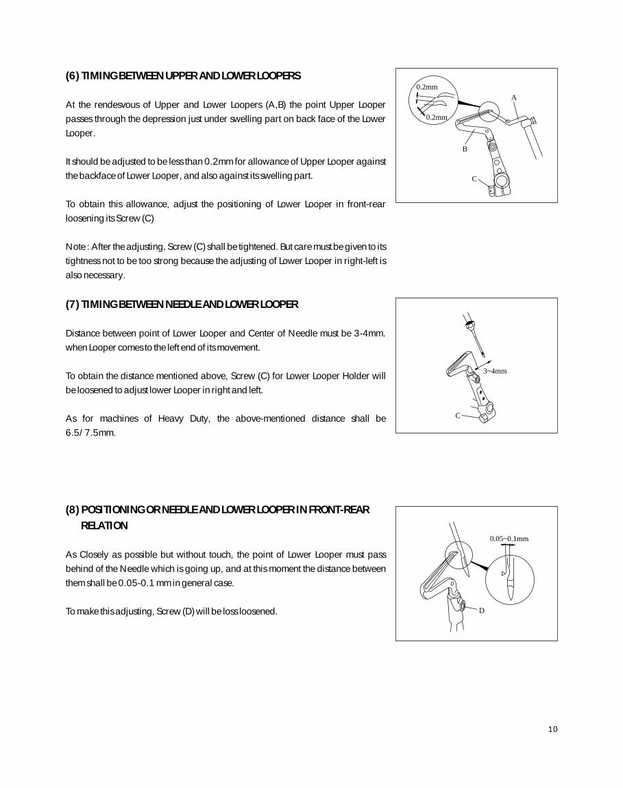
(6) TIMING BETWEEN UPPER AND LOWER LOOPERS
At the rendesvous of Upper and Lower Loopers (A,B) the point Upper Looper
passes through the depression just under swelling part on back face of the Lower
Looper.
It should be adjusted to be less than 0.2mm for allowance of Upper Looper against
the backface of Lower Looper, and also against its swelling part.
To obtain this allowance, adjust the positioning of Lower Looper in front-rear
loosening its Screw (C)
Note : After the adjusting, Screw (C) shall be tightened. But care must be given to its
tightness not to be too strong because the adjusting of Lower Looper in right-left is
also necessary.
(7) TIMING BETWEEN NEEDLE AND LOWER LOOPER
Distance between point of Lower Looper and Center of Needle must be 3-4mm.
when Looper comes to the left end of its movement.
To obtain the distance mentioned above, Screw (C) for Lower Looper Holder will
be loosened to adjust lower Looper in right and left.
As for machines of Heavy Duty, the above-mentioned distance shall be
6.5/7.5mm.
(8) POSITIONING OR NEEDLE AND LOWER LOOPER IN FRONT-REAR
RELATION
As Closely as possible but without touch, the point of Lower Looper must pass
behind of the Needle which is going up, and at this moment the distance between
them shall be 0.05-0.1 mm in general case.
To make this adjusting, Screw (D) will be loss loosened.
0.2mm
0.2mm
A
B
C
3~4mm
C
0.05~0.1mm
D
10
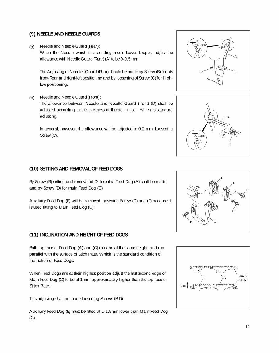
(9) NEEDLE AND NEEDLE GUARDS
(a)
(b)
(10) SETTING AND REMOVAL OF FEED DOGS
By Screw (B) setting and removal of Differential Feed Dog (A) shall be made
and by Screw (D) for main Feed Dog (C)
Auxiliary Feed Dog (E) will be removed loosening Screw (D) and (F) because it
is used fitting to Main Feed Dog (C).
(11) INCLINATION AND HEIGHT OF FEED DOGS
Both top face of Feed Dog (A) and (C) must be at the same height, and run
parallel with the surface of Stich Plate. Which is the standard condition of
Inclination of Feed Dogs.
When Feed Dogs are at their highest position adjust the last second edge of
Main Feed Dog (C) to be at 1mm. approximately higher than the top face of
Stitch Plate.
This adjusting shall be made loosening Screws (B,D)
Auxiliary Feed Dog (E) must be fitted at 1-1.5mm lower than Main Feed Dog
(C)
0~0.05mm
A
B C
1mm
C A Stichplate
0.2mm
D
E
C
E
F
D
A B
Needle and Needle Guard (Rear) :
When the Needle which is ascending meets Lower Looper, adjust the
allowance with Needle Guard (Rear) (A) to be 0-0.5 mm
The Adjusting of Needles Guard (Rear) should be made by Screw (B) for its
front-Rear and right-left positioning and by loosening of Screw (C) for High-
low positioning.
Needle and Needle Guard (Front) :
The allowance between Needle and Needle Guard (front) (D) shall be
adjusted according to the thickness of thread in use, which is standard
adjusting.
In general, however, the allowance will be adjusted in 0.2 mm. Loosening
Screw (C).
11
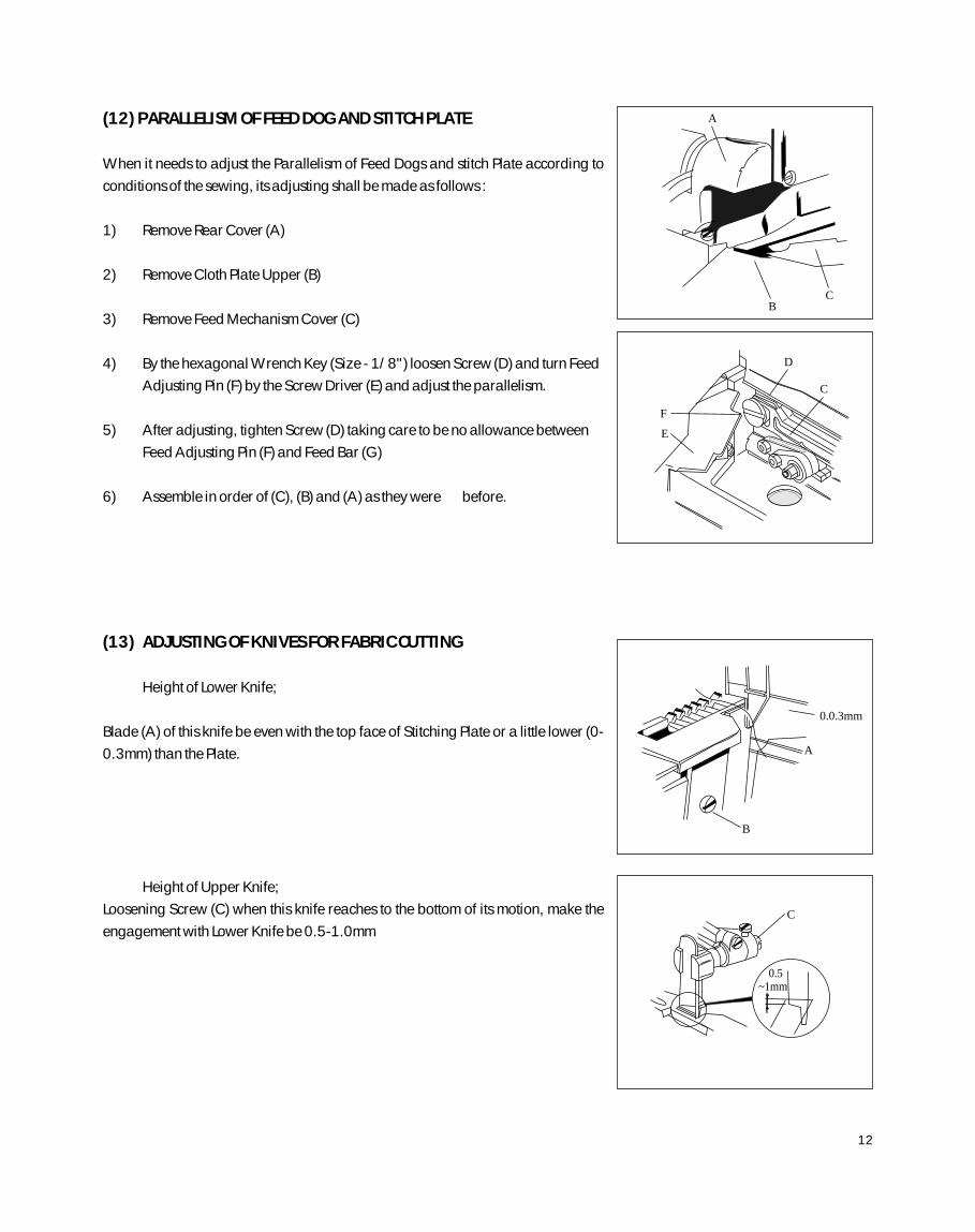
(12) PARALLELISM OF FEED DOG AND STITCH PLATE
When it needs to adjust the Parallelism of Feed Dogs and stitch Plate according to
conditions of the sewing, its adjusting shall be made as follows :
1) Remove Rear Cover (A)
2) Remove Cloth Plate Upper (B)
3) Remove Feed Mechanism Cover (C)
4) By the hexagonal Wrench Key (Size - 1/8") loosen Screw (D) and turn Feed
Adjusting Pin (F) by the Screw Driver (E) and adjust the parallelism.
5) After adjusting, tighten Screw (D) taking care to be no allowance between
Feed Adjusting Pin (F) and Feed Bar (G)
6) Assemble in order of (C), (B) and (A) as they were before.
(13) ADJUSTING OF KNIVES FOR FABRIC CUTTING
Height of Lower Knife;
Blade (A) of this knife be even with the top face of Stitching Plate or a little lower (0-
0.3mm) than the Plate.
Height of Upper Knife;
Loosening Screw (C) when this knife reaches to the bottom of its motion, make the
engagement with Lower Knife be 0.5-1.0mm
F
E
D
C
A
B
0.0.3mm
A
B C
C
0.5~1mm
12
(14) EXCHANGE OF LOWER KNIFE
Lower Knife can be removed pulling it off downwards after loosening of Screw (B)
To fit new Lower Knife or re-sharpened one, insert its blade from the underside and
tighten screw (B)
(15) SHARPENING OF KNIVES
Upper Knife is needles to be re-shapened about one year, because this knife is
made of Special Super Steel Alloy.
If sharpness of the cutting becomes blunt during the above period, resharpen
Lower Knife referring to figure to the left side.
Due to aforementioned reason, it is impossible to re-sharpen Upper Knife by the
ordinary Grinder, therefore, provisional one must be readied
always.
When re-sharpening of Upper Knife becomes necessary, please contact with us or
dealer who sold the machine to you.
The figure shows (Angle) of Upper Knife.
(16) ADJUSTING OF 2 NEEDLE 4 THREAD, OVERLOCKED STITCH
MACHINES
(16-1) FITTING OF NEEDLES
Both of two needles should be set correctly facing their scarfs towards the back side
of machines. Needles to be used must be those of same
kind. (System Dc x 1)
7.7
67
18
18 13
1.2 2.2
A
B
13
(16-2) THREADING
(Machines for Light Duties)
It should be made correctly
according to the figure.
A Needle Thread
(Left Needle)
B Needle Thread
(Right Thread)
C Upper Looper
Thread
D Lower Looper
Thread.
(Machines for Heavy Duties)
A Needle Thread
(Left Needle)
B Needle Thread
(Right Thread)
C Upper Looper
Thread
D Lower Looper
Thread.
A B
C D
A B
C D
-----(for Wooly Thread)
14
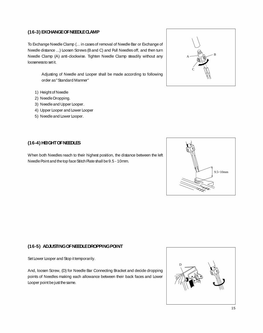
(16-3) EXCHANGE OF NEEDLE CLAMP
To Exchange Needle Clamp (... in cases of removal of Needle Bar or Exchange of
Needle distance ...) Loosen Screws (B and C) and Pull Needles off, and then turn
Needle Clamp (A) anti-clockwise. Tighten Needle Clamp steadily without any
looseness to set it.
Adjusting of Needle and Looper shall be made according to following
order as "Standard Manner"
1) Height of Needle
2) Needle Dropping.
3) Needle and Upper Looper.
4) Upper Looper and Lower Looper
5) Needle and Lower Looper.
(16-4) HEIGHT OF NEEDLES
When both Needles reach to their highest position, the distance between the left
Needle Point and the top face Stitch Plate shall be 9.5 - 10mm.
(16-5) ADJUSTING OF NEEDLE DROPPING POINT
Set Lower Looper and Stop it temporarily.
And, loosen Screw, (D) for Needle Bar Connecting Bracket and decide dropping
points of Needles making each allowance between their back faces and Lower
Looper point be just the same.
9.5~10mm
D
A B
C
15
(16-6) TIMING BETWEEN NEEDLE AND UPPER LOOPER
(a)
(b)
(16-7) TIMING BETWEEN UPPER AND LOWER LOOPERS
Refer to explanation of the same title on page 11.
(16-8) TIMING BETWEEN NEEDLE AND LOWER LOOPERS
In case of 2 needle machine but the Looper thread is caught by both needle.
Insert Upper Looper to Looper Bar (A) at the deepest, and tighten screw
(B) temporally,
When Needles descending, pass through back side of the Looper, tighten the
Looper closely to the right Needle by Screw (B) but without touch.
Distance between the center of left Needle and point of Upper Looper must
be 5 - 6 mm. when the Looper reaches to the left end of its movement.
To adjust the above distance :-
Open Front Cover and remove Looper Thread eyelet Supporter (D)
Loosen Screw (F) for Upper Looper Bar Driving Arm (E) by the Wrench of size
5/16.
In case of 2 Needle machines but the Looper, thread is caught only by the
right needle.
Fitting manner of Upper Looper and its relation to Needle are not different
from (a)
But, When Upper Looper comes to the left, make thread eye of the looper
point be at the center between two needles because the looper thread is
caught only by the right one among two needles.
Distance between centre of Needle and the point of Lower Looper must be 3 -
4 mm. when the Looper comes to the left end of its movement.
To obtain the distance mentioned above, screw (A) for Lower Looper Holder
will be loosened to adjust the Looper in right and the left.
D
E
F
C
B
5 ~6mm
3~4mm
A
B
A
5 ~6mm
16
(17) USE OF GUIDE AND OTHER ATTACHMENTS:
BLIND HEMMING MACHINE (DCZ - 200)
Turning the Adjusting Screw clockwise. Guide Holder will come up to the left and depth
of the seaming line becomes smaller. To the Contrary, turning it anti-clockwise the
depth shall be bigger. Therefore, the adjusting must be made according to nature of
materials in use. Tighten Stopper Screw (C) after the adjusting.
adjusting.
It is preferable that the allowance between Hemming Guide (E) and Guide Holder will
have the space just for a sheet of fabric.
And, make the point of Hemming Guide (E) come to the halfway on thickness of the
Guide Holder.
Blind Hemming Guide is assembled on DCZ - 200 machines as the "Standard
Equipment".
Tightening Screw (B), Guide shall be fitted to Stitch Plate Supporter just
underneath of Cloth Plate (Upper) (A)
In the blind hemming, depth of seaming line can be adjusted turning Adjusting
Screw (D) after loosening of Stopper Screw (C).
To adjust width of the blind hemming, move the guide (viny1 made ) of
Hemming Guide (E) in right-left loosening the Screw (F)
D
C
AB
E
F
17
(18) How to treat? ... on Sewing Troubles!
Trouble and Reasons Countermeasures and Treatment Page
A. SKIP - STITCHING
a) Incorrect threading Refer to "Threading" 4 - 5, 15
b) Improper fitting of Needle Refer to "Fitting of Needle" and "Height of Needle". 4, 14
(in facing and height) 10, 16
c) Destruction and blend at needle point Change with new needle
d) Improper relation between Refer to:- 10 - 12
Needle and Looper "Timing between Needle and Upper, Lower Loopers", 17
"Positioning of Needle and Lower Looper in
Front-Rear Relation".
"Timing between Upper and Lower Loopers".
e) Wearing at the Point of Upper Readjust by oilstone or emery paper,
and Lower Loopers otherwise change with new looper.
f) Improper relation between Refer to "Needle and Needle Guard". 12
Needle and Needle Guard
G) Excessive Strength or weakness Adjust to obtain suitable tension.
for thread tension
B. THREAD BREAKAGE
a) Incorrect threading Refer to "Threading" 4 - 5, 15
b) Improper fitting of Needle Refer to "Fitting of Needle" 4, 14,
(in facing and height) and "Height of Needle" 10,16
c) Excessive strength for Adjust to obtain suitable tension.
thread tension
d) Poor finish of groove or eye of Needle Change with new needle.
e) Poor quality of thread Use thread of better quality
f) Thicker thread comparing Change with suitable thread or needle.
with size of needle eye
g) Improper relation between Same as A - d.
h) Scratches on Stitch Plate, Needle, Looper, Readjust by oilstone or emery Paper.
Presser Foot tongue, Eyelet and etc.
C. NEEDLE BREAKAGE
a) Improper fitting of Needle (in facing and height) Refer to "Fitting of Needle"and "Height of Needle". 4, 14,10, 16
b) Bend of needle point Change with new needle
18
Troubles and Reasons Countermeasures and Treatments Page
c) Improper relation between Same as A - d.
Needle and Looper
d) Improper relation between Refer to "Needle and Needle Guard 12
Needle and Needle Guard
D. LOOSENESS ON SEWING FINISH
a) Incorrect threading Refer to "Threading". 4 - 5, 15
b) Thicker thread comparing Change with Suitable thread
with size of needle eye or needle.
c) Improper operation of Tension Disc Make Disks operate smoothly
cleaning dusts inside them.
d) Improper relation between Same as A - d.
e) Improper positioning of Eyelets Refer to :- 9 - 10
"Tension of Needle Thread"
"Tension of Lower Looper Thread".
"Tension of Upper Looper Thread".
E. LACK OF UNIFORMITY ON SEWING FINISH
a) Incorrect threading Refer to "Threading" 4 - 5, 15
b) Uneven thickness of thread Use thread of better quality.
c) Poor finish of eyes on Eyelets Polish their eyes to be smooth
by emery paper or the like.
d) Improper Positioning of Refer to :- 9 - 10
"Tension of Needle Thread",
"Tension of Lower Looper Thread".
"Tension of Upper Looper Thread".
e) Blunt cutting of Knives Refer to "Adjusting of Knives 13 - 14
for Fabric Cutting" and
"Sharpening of Knives".
f) Incorrect fitting of Lower Knife Refer to "Adjusting of Knives 13
for Fabric Cutting".
F. TOO MUCH SEWING WRINKLES
a) Excessive thickness of Needle Select suitable needle to thread and fabric.
b) Incorrect adjusting of differential ratio Refer to "Adjusting of Differential feeding". 9
c) Improper pressure on Presser Foot Refer to "Pressure of Presser Foot" 5
d) Excessive strength for thread tension Adjust the tension suitably.
19
Troubles and Reasons Countermeasures and Treatments Page
e) Blunt cutting of Knives Same as E - e.
f) Unfitting of the cutting width with Make both of width fit suitably, Otherwise
Stitch Tongue on Stitch Plate. change with new Stitch Plate.
g) Improper fitting of Feed Dogs Refer to "Height of Feed Dogs" and 12 - 13
"Parallelism of Feed Dogs and Stitch Plate".
G. INSUFFICIENT FLOW OF CHAIN-OFFS
a) Incorrect threading Refer to "Threading". 4 - 5, 15
b) Excessive strength or weakness Adjust to obtain the suitable tension
for thread tension
c) Improper positioning of Eyelets Same as D - e.
d) Improper relation between Same as A - d.
Needle and Looper
e) Scratches on Stitch Plate, Needle, Looper, Readjust by emery paper and the like.
Presser Foot Tongue, Eyelet & etc.
H. DAMAGES ON FABRIC BY DOGS
a) Excessive sharpness of Dog Round it off by oilstone
b) Excessive pressure on Make it be as weak as possible 5
Pressure Foot Refer to "Pressure of Presser Foot".
I. TOO LARGE OPENING ON NEEDLE PENETRATION
a) Bluntness of needle point Change with new needle
b) Thicker needle comparing Change with thinner needle
with fabric
c) Angular edge of slot for Round off its edge by emery
needle drop on Stitch Plate paper or the like.
18. Additional Note
Items mentioned in this booklet are for the operation and adjusting of Class DCZ - 200 machines. However, according to the
special conditions like as nature of fabrics, threads or others, there may be some cases to have to make other arrangements
particularly. In such cases, please adjust again to be suitable to special conditions.