AVTMTDR3090 Rev 2 Dec 2012 INSTRUCTION MANUAL Digital Time Domain Reflectometer Models T3090, T3090 SX, T3090 T & T3090 SXT HIGH VOLTAGE EQUIPMENT Read this entire manual before operating. M Valley Forge Corporate Center 2621 Van Buren Avenue Norristown, PA 19403-2329 U.S.A. 610-676-8500 www.megger.com
Transcript
AVTMTDR3090 Rev 2
Dec 2012
INSTRUCTION MANUAL Digital Time Domain Reflectometer
Models
T3090, T3090 SX, T3090 T & T3090 SXT
HIGH VOLTAGE EQUIPMENT
Read this entire manual before operating.
M
Valley Forge Corporate Center 2621 Van Buren Avenue Norristown, PA 19403-2329 U.S.A. 610-676-8500
www.megger.com
INSTRUCTION MANUAL Digital Time Domain Reflectometer
The information presented in this manual is believed to be adequate for the intended use of the product. The products described herein should not be used for purposes other than as specified herein. Specifications are subject to change without notice.
WARRANTY
Products supplied by Megger are warranted against defects in material and workmanship for a period of one year following shipment. Our liability is specifically limited to replacing or repairing, at our option, defective equipment. Equipment returned for repair must be shipped prepaid and insured. Contact your local MEGGER representative for instructions and a return authorization (RA) number. Please indicate all pertinent information, including problem symptoms. Also specify the serial number and the catalog number of the unit. This warranty does not include batteries, lamps or other expendable items, where the original manufacturer’s warranty shall apply. We make no other warranty. The warranty is void in the event of abuse (failure to follow recommended operating procedures) or failure by the customer to perform specific maintenance as indicated in this manual.
Voltages of greater than 50 V applied across dry unbroken human skin are capable of producing heart fibrillation if they produce electric currents in body tissues which happen to pass through the chest area.[citation needed] The electrocution danger is mostly determined by the low conductivity of dry human skin. If skin is wet, or if there are wounds, or if the voltage is applied to electrodes which penetrate the skin, then even voltage sources below 40 V can be lethal if contacted. Additionally research has shown that where the skin has been compromised, very small voltage of up to 3V can kill.
Accidental contact with high voltage supplying sufficient energy will usually result in severe injury or death. This can occur as a person's body provides a path for current flow causing tissue damage and heart failure. Other injuries can include burns from the arc generated by the accidental contact. These can be especially dangerous if the victim's airways are affected. Injuries may also be suffered as a result of the physical forces exerted as people may fall from height or be thrown a considerable distance.
M
AVTMTDR3090 Rev 2 Dec 2012
i
Table of Contents
1 Getting to Know Your TDR ................................................................................................................ 1
2 Getting Started ........................................................................................................................................ 3 Power ON / OFF ......................................................................................................................... 3 The Function of the Rotary Knob / Controller Knob ........................................................... 4 Set-up of Default Parameters and Customer Selectable Parameters ..................................... 5
Date /Time ................................................................................................................................. 7 Language ..................................................................................................................................... 7 Default Settings .......................................................................................................................... 7 Measurement Unit ..................................................................................................................... 8 Cable velocity V/2 ..................................................................................................................... 9 Trigger delay time ...................................................................................................................... 9 Measurement Start ................................................................................................................... 10 Set-up Start Marker.................................................................................................................. 11 Cable list .................................................................................................................................... 12 Thumper Model Selection & Effect on Step-by-Step Instructions .................................. 13 User mode ................................................................................................................................. 13 Backlight settings ..................................................................................................................... 14 Stored Traces ............................................................................................................................ 14 System Information ................................................................................................................. 15 Change Password ..................................................................................................................... 16
Set-up for specific Menu Style .................................................................................................. 19 SIMPLE -, EXTENDED - , DISABLED Options .......................................................... 19
Export & Import Feature for TDR feature configuration ................................................... 21 List of Customer selectable TDR features .............................................................................. 23
5 QUICK-STEPS and EXPERT Style Menus ................................................................................... 25
General Introduction to QUICK-STEPS & EXPERT Style Menus .................................. 25 QUICK-STEPS style menu for ARM Fault Locating ........................................................... 26 EXPERT style menu for ARM Fault Locating ...................................................................... 27
M
AVTMTDR3090 Rev 2 Dec 2012
ii
6 STEP-by-STEP Style Menu ................................................................................................................ 29 List of Fault locating Systems with available Step-by-Step Style Menus ............................ 30 LOCATE "Arc Reflection Method" (ARM®) using STEP-by-STEP ................................. 31 Performing a Hipot Test with the SG-15 Allegheny Menu (English) in the “STEP-by-STEP” style menu ....................................................................................................................... 33
7 Utility Menu .......................................................................................................................................... 35
The Digital Time Domain Reflectometer T 3090 is a very compact, portable TDR for fault locating on primary / secondary power cables. All essential components of the unit are mounted in a durable, compact, water protected, portable carrying case.
The unit will operate on AC voltage (90-240V / 50-60 Hz). The AC, Signal and Trigger cables are water protected and located on the backside of the unit.
UPON RECEIPT OF YOUR DELIVERY
Prior to operation, check for loosened hardware or damage incurred during transit. If these conditions are found, a safety hazard could exist, DO NOT attempt to operate equipment.
Please contact Megger as soon as possible.
Please check your delivery against:
a) your order b) our advice note c) the item delivered, and d) the parts list
Any shortages must be reported immediately.
The T3090 TDR is shipped complete with the following accessories:
Element Description
AC Power Cord
Alligator / BNC Splitter
Coax Extension Cable
USB Memory Stick
Not shown 2 Velcro strips to secure TDR enclosure to base
M
AVTMTDR3090 Rev 2 Dec 2012
iv
M
AVTMTDR3090 Rev 2 Dec 2012
v
STANDARD MANUAL CONVENTIONS
This manual uses the following conventions:
Bold indicates emphasis or a heading.
NOTE: is used to set off important information from the rest of the text.
F A WARNING symbol alerts you to a hazard that may result in equipment damage, personal injury, or death. Carefully read the instructions provided and follow all safety precautions.
G A CAUTION symbol alerts you that the system may not operate as expected if instructions are not followed.
AVTMTDR3090 Rev 2 Dec 2012
1
1 Getting to know your TDR
CONTROLS & CONNECTIONS
Display:
Rotary Knob – Control Knob (turn & click)
ON / OFF” button
Ventilation Slots
AC power connector
Signal Port
“Coax connectors for Trigger, ICE and TDR-Signal
USB Port
2 Fuses 230V 2 A
100V-240V AC 50-60 Hz/ 50 VA
M
AVTMTDR3090 Rev 2 Dec 2012
2
M
AVTMTDR3090 Rev 2 Dec 2012
3
2 Getting Started
NOTE: Typically the TDR has been set-up in the factory for use with the specific fault locating system for primary cables, which it has been purchased for. There may be reasons why the user must go through this process again. MEGGER encourages user to call the factory in order to assist with this process, which can be done within 30 minutes.
Typical connections for primary fault locating applications: Connect the AC power cord to the TDR and plug it into a 120/230VAC outlet provided by the fault locating system.
Typically the Signal and Trigger Cables form the fault locating system or the filter are connected to the respective BNC ports on the back side of the T3090 (if an internal trigger was ordered as an option, only the signal cable gets connected).
Typical connections for secondary fault locating applications:
Connect the AC Power cord to the TDR and plug it in a 120V /230V outlet or connect it to a 120V /230V “pigtail” and clip its lead between one hot leg and the neutral.
Take the Coax extension cable and connect one end to the signal port at the TDR and its other end to the alligator / BNC splitter.
NOTE: Do not connect TDR to hot primary or hot secondary cables!
Power ON / OFF
Push toggle switch to turn unit on (light will come on).After the initial boot-up, the Main menu will appear. The unit has a wide voltage input power supply from 100-240VAC.
M
AVTMTDR3090 Rev 2 Dec 2012
4
The Function of the Rotary Knob / Controller Knob
Control Knob : "Turn" & "Click" & "Turn"
Turning Control Knob Selects function.
Clicking Control Knob Activates Selected Function and puts a red circle around the icon.
Turning Control Knob in the activated state
Changes the numeric value of the activated function, if function allows.
Getting Started
AVTMTDR3090 Rev 2 Dec 2012
5
Set-up of Default Parameters and Customer Selectable Parameters
Please verify before its first use that theT3090 has been properly set up. In order to perform this task, the T3090 must be in the “Expert Style Menu” (see more details in Section 3 of the instruction manual regarding “Menu Style”).
If the T3090 is in the EXPERT style menu , thecog wheel symbol in the lower left corner of screen will be visible, if not go to EXPERT Style, pls see below
“Quick-Steps” Style Menu No “Cog Wheel ” symbol visible in the main screen
1. Push on any icon for a couple seconds to activate password screen, zero will show.
.
2. Click the rotary knob. Zero changes to *.
3. Click 3 more times. That will enter a total of 4 zeros = factory preset
password. The "Cog Wheel ” symbol will be always visible in lower left corner of the main screen
M
AVTMTDR3090 Rev 2 Dec 2012
6
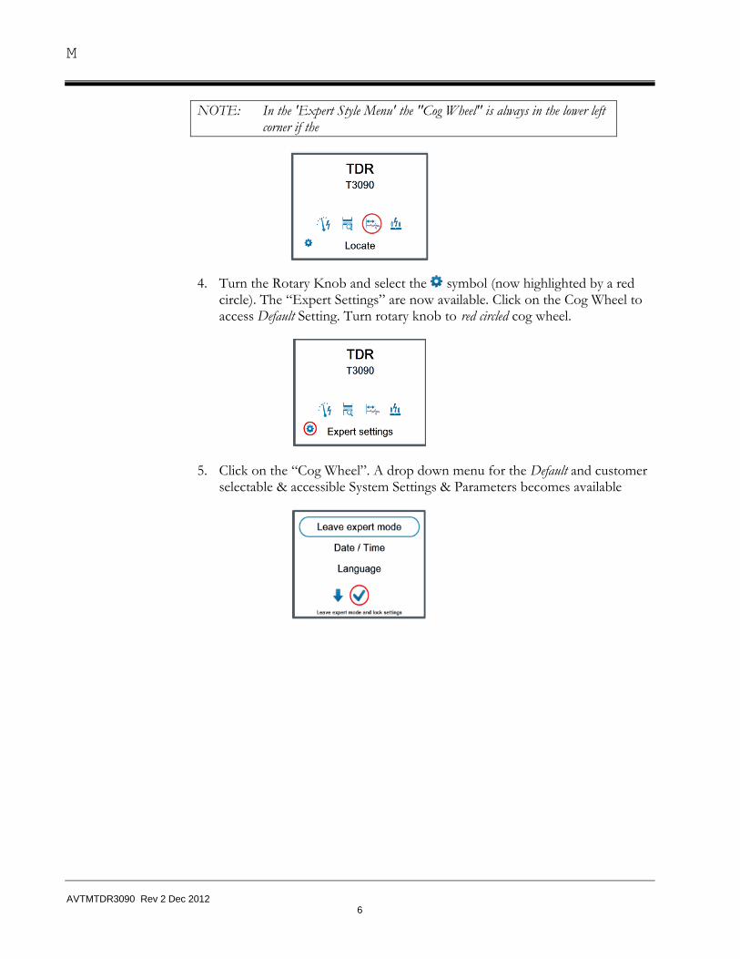
NOTE: In the 'Expert Style Menu' the "Cog Wheel" is always in the lower left corner if the
4. Turn the Rotary Knob and select the symbol (now highlighted by a red circle). The “Expert Settings” are now available. Click on the Cog Wheel to access Default Setting. Turn rotary knob to red circled cog wheel.
5. Click on the “Cog Wheel”. A drop down menu for the Default and customer selectable & accessible System Settings & Parameters becomes available
Getting Started
AVTMTDR3090 Rev 2 Dec 2012
7
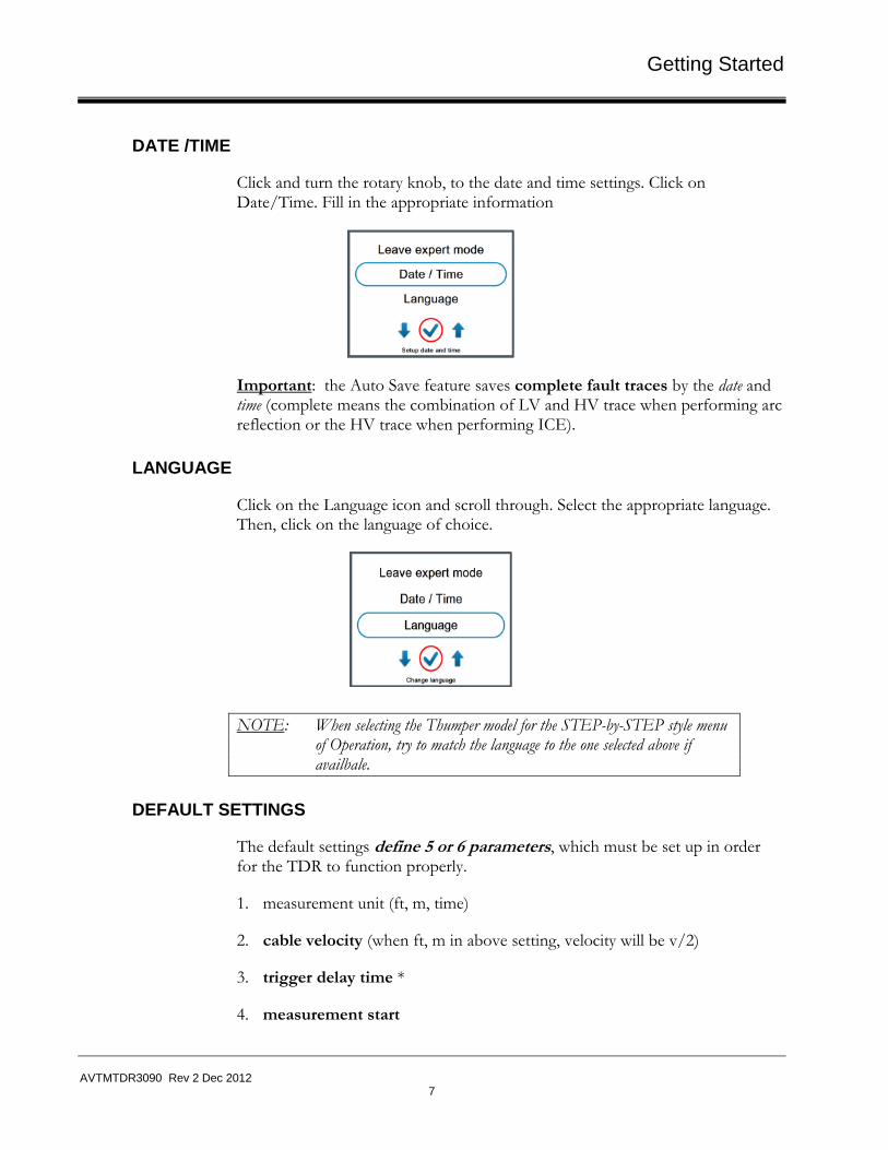
DATE /TIME
Click and turn the rotary knob, to the date and time settings. Click on Date/Time. Fill in the appropriate information
Important: the Auto Save feature saves complete fault traces by the date and time (complete means the combination of LV and HV trace when performing arc reflection or the HV trace when performing ICE).
LANGUAGE
Click on the Language icon and scroll through. Select the appropriate language. Then, click on the language of choice.
NOTE: When selecting the Thumper model for the STEP-by-STEP style menu of Operation, try to match the language to the one selected above if availbale.
DEFAULT SETTINGS
The default settings define 5 or 6 parameters, which must be set up in order for the TDR to function properly.
1. measurement unit (ft, m, time)
2. cable velocity (when ft, m in above setting, velocity will be v/2)
3. trigger delay time *
4. measurement start
M
AVTMTDR3090 Rev 2 Dec 2012
8
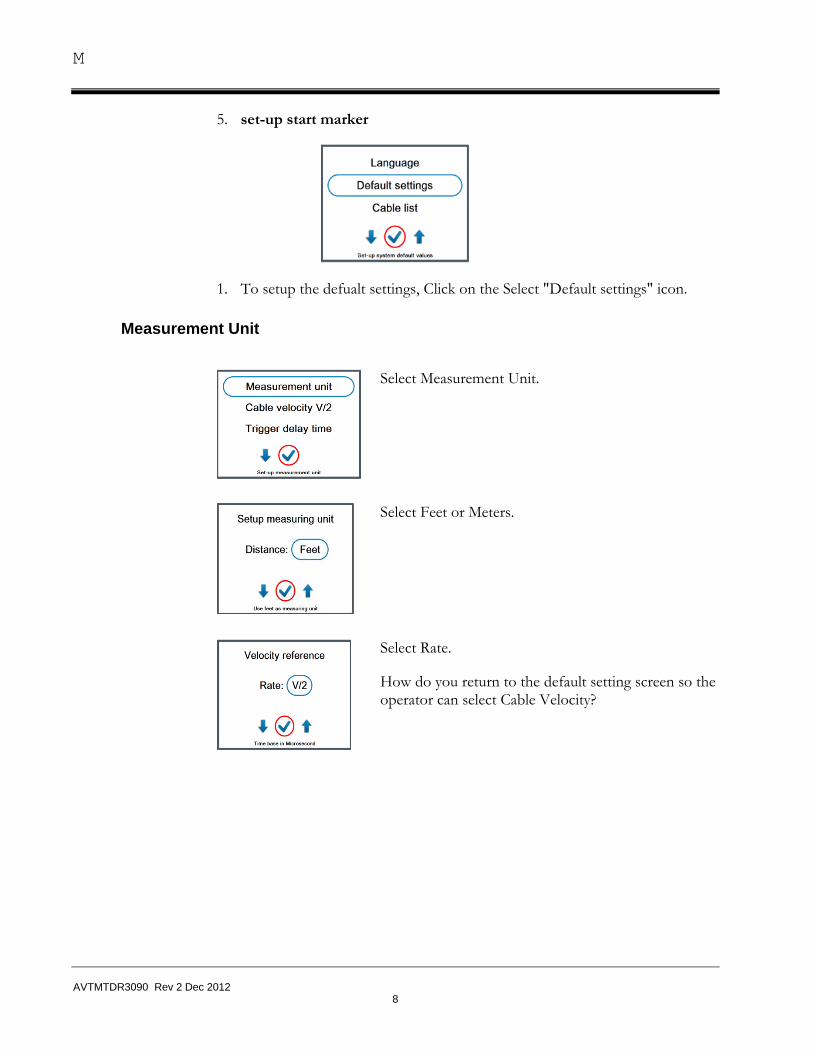
5. set-up start marker
1. To setup the defualt settings, Click on the Select "Default settings" icon.
Measurement Unit
Select Measurement Unit.
Select Feet or Meters.
Select Rate.
How do you return to the default setting screen so the operator can select Cable Velocity?
Getting Started
AVTMTDR3090 Rev 2 Dec 2012
9
Cable velocity V/2
Select Cable velocity V/2.
Select the appropriate velocity. How do you return to the default setting screen so the operator can select Trigger Delay time
Trigger delay time
Delay time: the time between releasing the HV surge and the time to release the TDR pulse. The delay time allows the flash-over voltage to build up an arc before the measurement takes place. If the delay time is too short, Flash-over & resulting arc is not stable & TDR reflections may not be clear or nonexistent.
If the delay time is too long, the arc extinguishes before the TDR pulse reaches the fault, no reflection of the TDR pulse, no fault detected.
Trigger delay values: SG15/25, SPG32 [700µsec] Units with M219 filter [1.3msec]
Select the appropriate delay time.
How do you return to the default setting screen so the operator can select Trigger Delay time
M
AVTMTDR3090 Rev 2 Dec 2012
10
Measurement Start
Measurement start defines how a HV test is started, automatic or manual and relates to how the HV is released.
MANUAL means that after PUSH GREEN BUTTON for HV-O”, the unit will go to a pre-set voltage, but will not release the shot unless the operator manually releases the shot individually.
AUTOMATIC means that pushing “PUSH GREEN BUTTON for HV-ON” the unit will go to a preset voltage, and once reached, releases the shot without any additional intervention by the operator.
NOTE: AUTOMATIC is typical for North American Market.
How do you return to the default setting screen so the operator can select Trigger Delay time
Getting Started
AVTMTDR3090 Rev 2 Dec 2012
11
Set-up Start Marker
Set-up Start Marker positions the Start Marker at the end of the actual test lead and its physical end.
Select Set-up Start Marker.
First: A TDR reflection measurement is taken with the ends of the HV test lead open. Press Knob to continue.
Then the gain setting is adjusted (typical -12) and confirmed and a copy of the trace is frozen.
A second trace is recorded with the ends of the HV test lead shorted to each other, which will show a significant change.
M
AVTMTDR3090 Rev 2 Dec 2012
12
The marker is automatically placed on the position where both traces start to split.
If required, the marker can be manually adjusted. This setting of the start marker will be stored after being prompted as the default and should only be changed if the length of the test lead is changed.
Cable list
By means of the Cable list one can quickly set the appropriate propagation velocity during a reflection measurement by selecting the correct velocity form the list based on voltage class, insulation thickness & wire size:
The Cable list can be set as the default list, exported or imported, or removed altogether. The cable list can be edited (Chapter 8) and imported (XML file) according to specific preferences and then shared among multiple units.
If a specific cable is not on the list, select the closest cable (in terms of XLPE, EPR, PILC voltage class and conductor size). However, if the cable is commonly used by a customer, its velocity should be determined and added to the cable list (see Chapter 8, Utility Menus, for details).
Getting Started
AVTMTDR3090 Rev 2 Dec 2012
13
Thumper Model Selection & Effect on Step-by-Step Instructions
If the customer prefers to use the Step-by-Step Style Menu to operate a specific thumper system in combination with the T3090, he must select the specific thumper model from the drop down menu “Thumper Model” (in the example SWG).
For all Megger thumper models the Step-by-Step Style menus have been generated, at least for Arc Reflection and Direct Thump Mode, for competitive thumper systems they can be generated together with the customer for a nominal fee (example CDS20-10 Connexus).
NOTE: If “NONE” is selected for the Thumper Model, the “Quick-Steps Style Menu” and the “EXPERT Style Menu” are available, but none of the Step-by-Step style menus are available!
User mode
User mode allows the operator to select the default style menu which is active after switching unit on (after start-up). It is recommended to set to QUICK STEPS.
This will always make the QUICK STEPS Style & STEP-by-STEP Style menus available to the user without a password (Step-by-Step only if specific).
M
AVTMTDR3090 Rev 2 Dec 2012
14
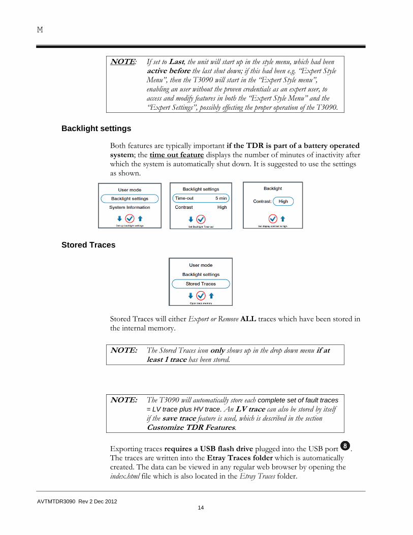
NOTE: If set to Last, the unit will start up in the style menu, which had been active before the last shut down; if this had been e.g. “Expert Style Menu”, then the T3090 will start in the “Expert Style menu”, enabling an user without the proven credentials as an expert user, to access and modify features in both the “Expert Style Menu” and the “Expert Settings”, possibly effecting the proper operation of the T3090.
Backlight settings
Both features are typically important if the TDR is part of a battery operated system; the time out feature displays the number of minutes of inactivity after which the system is automatically shut down. It is suggested to use the settings as shown.
Stored Traces
Stored Traces will either Export or Remove ALL traces which have been stored in the internal memory.
NOTE: The Stored Traces icon only shows up in the drop down menu if at least 1 trace has been stored.
NOTE: The T3090 will automatically store each complete set of fault traces
= LV trace plus HV trace. An LV trace can also be stored by itself if the save trace feature is used, which is described in the section Customize TDR Features.
Exporting traces requires a USB flash drive plugged into the USB port . The traces are written into the Etray Traces folder which is automatically created. The data can be viewed in any regular web browser by opening the index.html file which is also located in the Etray Traces folder.
Getting Started
AVTMTDR3090 Rev 2 Dec 2012
15
OR
SYSTEM INFORMATION
IMPORTANT: Displays the detailed hardware and software configuration, as well as the serial number of the unit. This is a View Only screen, which is based on the factory setting. All possible screens are shown below.
NOTE: Sectionalizing will say YES or NO or COMED (COMED version) depending on what customer ordered.
As mentioned above, all System Information screens are “view only”; they can be very helpful for the customer to determine the exact configuration of the TDR before calling the Help/Service Line for MEGGER / SebaKMT.
M
AVTMTDR3090 Rev 2 Dec 2012
16
CHANGE PASSWORD
Access to change the password, is required to enter in the Expert Style Menu and the Expert Settings.
NOTE: Factory sets temporary Password as “0000”; if the password is changed by customer, it is recommended to keep a record of the new password.
To change the password:
1. Select Change password.
2. Click the rotary knob. Zero changes to *.
3. Click 3 more times. That will enter a total of 4 zeros = factory preset password.
AVTMTDR3090 Rev 2 Dec 2012
17
3 TDR Operation
Explanation of 3 style menus to operate TDR
The T3090 is the only TDR in the market to offer 3 “Menu Styles” for its operation to its user: "QUICK STEPS", "EXPERT" and "STEP-by-STEP" style menus of operation
"QUICK STEPS", and "EXPERT" style menus allow the user to custom configure the TDR feature as he / she sees them fit best the skill levels in their organization.
"STEP-by-STEP" style menu, is hard-scripted to emulate a conventional specific fault locating system, and therefore does not allow for any custom configuration of TDR features
"STEP-by-STEP" is typically intended for the "casual & inexperienced" operator, it provides all necessary steps in the operation of a specific fault locating system from connecting the tests leads, pre-locating, pin-pointing the fault, operating the Hipot or Burner.
NOTE: "STEP-by-STEP" can be easily recognized by its symbol of 2 side-by-side feet.
The purpose of this "3 layer" approach is as follows: Show only what is absolutely necessary.
"simple option / extended option" vs. “disabled option”:
If the "simple option" or "extended option" icons are not activated, the feature has been "disabled". A feature should be marked "disabled", if it can be reasonably assumed that its availability and application by an inexperienced operator could or would render the TDR useless as the consequence of an
M
AVTMTDR3090 Rev 2 Dec 2012
18
incorrect choice and combination of TDR settings and their values (e.g. pulse width, gain, etc.).
"simple option" vs. "extended option":
A feature that is quite commonly used should be marked "simple option", conversely a feature, which is hardly ever used, but could be beneficial to have in very rare instances, would be marked "extended option", which "hides" it, but still makes it available within the same menu level if needed.
AVTMTDR3090 Rev 2 Dec 2012
19
4 Customize TDR Features
Set-up for specific Menu Style
By clicking on "Configure Menu Options" the 3 style menus become visible and allow you to configure the 20 (18) available TDR features.
SIMPLE -, EXTENDED - , DISABLED Options
Follow the chart below to access the style menu required.
Quick Steps Style
By clicking on a new screen with the 1st feature
opens up,which by turning the control knob will show 3 choices for the availabilty of this feature in the Quick-Steps Style menu.
1st Feature
2nd Feature
3rd Feature
M
AVTMTDR3090 Rev 2 Dec 2012
20
After a decision amongst the 3 choices has been made for the 1st feature, the 2nd feature “Xfmr sensitivity” is selected and the same process is applied to it; this process is repeated till a choice has been set up for the last feature “Zoom In/Out” (all screens are shown below).
The entire process for the “Quick Steps” style menu is finished by selecting “return” and clicking on it .
Expert Style
By clicking on a new screen with the 1st feature
opens up,which by turning the control knob will show 3 choices for the availabilty of this feature in the Expert Style menu.
After a decision amongst the 3 choices has been made for the 1st feature, the 2nd feature “Xfmr sensitivity” is selected and the same process is applied to it; this process is repeated till a choice has been set up for the last feature “Zoom In/Out” (all screens are shown below).
The entire process for the “Expert” style menu is finished by selecting “return” and clicking on it .
Customize TDR Features
AVTMTDR3090 Rev 2 Dec 2012
21
NOTE: On newer software versions there are 18 features (Opt Gain & Save Full trace to USB are removed
Export & Import Feature for TDR feature configuration
After completing the selection for all features for the EXPERT style menu,
1. click return and the following screen will appear.
2. Click return again and the EXPORT / IMPORT feature can be selected.
It allows you to copy all feature selections for both the QUICK-STEPS and the EXPERT style menus to a USB flash drive (EXPORT) and then to import that very selection via the USB flash drive and to another unit (helpful tool) when customer has multiple units
3. If the rotary knob is turned from the checkmark to the circled X , this submenu is left and the screen IMPORT-EXPORT (see above) returns.
4. After selecting IMPORT or EXPORT follow the instructions and click till the FINISHED message appears.
M
AVTMTDR3090 Rev 2 Dec 2012
22
5. After clicking the checkmark in the FINISHED screen, click on RETURN on the following screen and then again on the next screen till the MAIN screen appears.
MAIN screen
6. Turn Rotary knob to the cog wheel in the lower left corner and click on it.
This will access the scroll down menu in the EXPERT mode, click on
.
The MAIN screen reappears, now in the QUICK STEPS mode (no cogwheel visible, see also page 7 for detailed description).
After setting all default values and customizing the configuration for the TDR features in both the EXPERT and QUICK-STEPS style menus, the T3090 is now prepared to be used for cable fault locating.
Customize TDR Features
AVTMTDR3090 Rev 2 Dec 2012
23
List of Customer selectable TDR features
FEATURE Description Simple Option
Extended Option
Disabled Option
Cable Velocity Specific for each cable: can be looked up in cable list, should be as close as possible
X
Xfmr Sensitivity* Allows to decrease sensitivity for transformer identification
X
Delay Time (Trigger Delay)
Adjust time to synchronize HV shot and TDR shot
X
Disable live Trace If live trace is disabled the TDR must be “fired” after each adjustment to get an updated trace
X
Graphic view The TDR trace is shown in graphic form to show the impedance changes
X
Enable live Trace Only required if live trace can be disabled
X
Alphanumeric View Mo impedance changes are shown, only the alphanumeric values for the cable end and the fault
X
Opt Gain Service Only
Search for Xfmr* Allows to include or exclude the search for transformers
X
Gain Adjusts the trace amplification X
Trace on hold Allows to store multiple traces on same screen (phase comparison)
X
Adjust End Marker Allows to adjust end marker by hand override automatic)
X
Adjust Start Marker Allows the adjustment of the start marker; should be always adjusted as part of the set-up process
X
Recall Stored Traces Allows to recall previously stored traces for comparison
X
Cursor Allows to adjust cursor (typically the fault marker) by hand (override automatic)
X
Additional Marker Allows to position additional marker(s) to identify accessories, e.g. splices , transformers
X
M
AVTMTDR3090 Rev 2 Dec 2012
24
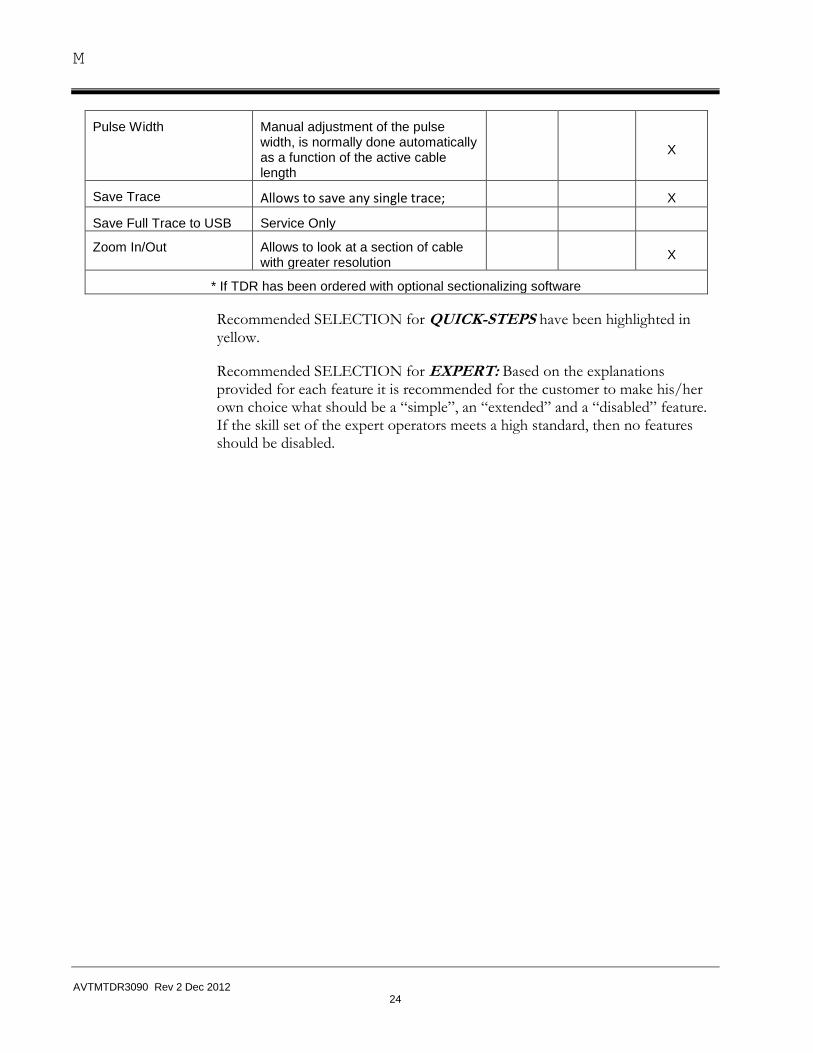
Pulse Width Manual adjustment of the pulse width, is normally done automatically as a function of the active cable length
X
Save Trace Allows to save any single trace; X
Save Full Trace to USB Service Only
Zoom In/Out Allows to look at a section of cable with greater resolution
X
* If TDR has been ordered with optional sectionalizing software
Recommended SELECTION for QUICK-STEPS have been highlighted in yellow.
Recommended SELECTION for EXPERT: Based on the explanations provided for each feature it is recommended for the customer to make his/her own choice what should be a “simple”, an “extended” and a “disabled” feature. If the skill set of the expert operators meets a high standard, then no features should be disabled.
AVTMTDR3090 Rev 2 Dec 2012
25
5 QUICK-STEPS and EXPERT Style Menus
General Introduction to QUICK-STEPS & EXPERT Style Menus
When the T3090 is operated in these 2 menu styles, and the choice of the thumper model has been set to “NONE”, it will operate like any other stand-alone TDR when performing fault locating. The thumper system is operated independently from the TDR.
NOTE: Using the QUICK-STEPS menu style requires the operator to be familiar with the operation of the thumper system
Using the EXPERT menu style requires the operator to be familiar with both the operation of the thumper system as well as the TDR
The QUICK-STEPS style menu allows moving very quickly through the TDR, and is typically used when no TDR adjustments are expected to become necessary (e.g. URD fault locating), it still re- quires the knowledge to operate the thumper and is not intended for the casual user who is not familiar with the specific thumper.
In QUICK-STEPS the number of available TDR features is limited to a bare minimum in order to not confuse the operator; essentially he will follow the red circled steps and typically makes no TDR adjustments (may be the velocity, if not working on a typical URD cable). The EXPERT style menu functions are very similar, except the operator has access to select from a list of 18 TDR features. They allow him / her to “tune” the TDR to the best possible trace image, which is sometimes required on difficult to find faults, but require an understanding of the TDR features.
M
AVTMTDR3090 Rev 2 Dec 2012
26
QUICK-STEPS style menu for ARM Fault Locating
The T3090 can be ordered either with a single or up to 4 fault locating method. The T3090 with LOCATE, which stands for ARM fault locating, represents its most basic version (left).
ARM Method
TDR Method
SECTIONALIZING Method
ARM Method
SURGE PULSE (ICE) Method
Basic T3090
Configuration
NAZFTA Market
Typical in Europe
Typical in MED/FE
Typical; in NAFTA
URD Trouble
Shooting in MV Hoops
Worldwide
State of the Art
Method for Solid Dielectric Cables
Typical in Europe
Typical in MED/FE
Excellent for PILC & long cables
If any of the other fault locating methods, TDR, Sectionalizing, Surge Pulse, are available to the user, they what?????
Typical QUICK-STEPS ARM fault locating process, if user follows automatic sequence without making adjustments, follow red arrow, if user wants to override automatic & adjusts manually the TDR features, follow blue arrow.
Accepting the results from the QUICK-STEP’s, no user TDR interaction required.
If you want to modify the automatic cable end result from QUICK-STEP’s, you can make the required adjustment by turning the rotary control knob to the
symbol manually adjusting the end marker; in this position the user can also select any feature, which has been made available in the QUICK-STEPS menu according to Para 4.1., page 13 and Para 4.3, page 15 (the example shows 3 selected features).
QUICK-STEPS and EXPERT Style Menus
AVTMTDR3090 Rev 2 Dec 2012
27
Selected TDR Features in Quick Steps
EXPERT style menu for ARM Fault Locating
Follow para 2.2., page 7 to change from QUICK-STEPS to EXPERT menu style.
The “cog wheel” symbol in the lower left hand corner indicates that the EXPERT menu style is active.
Example: being activated
Selected as “SIMPLE” options in TDR Feature Menu
Selected as “EXTENDED” options in TDR Feature Menu
Cursor
Velocity
End Marker
M
AVTMTDR3090 Rev 2 Dec 2012
28
M
AVTMTDR3090 Rev 2 Dec 2012
29
6 STEP-by-STEP Style Menu
“STEP-by-STEP” is typically intended for the “casual & inexperienced” operator, it provides all necessary steps in the operation of a specific fault locating system, which can comprise a number of different operating modes depending on the particular fault locating System. The STEP-by-STEP style menu will explain every step necessary to operate the system, starting from connecting the test leads.
After selecting the operating mode on the main screen and confirming it by c licking on the control knob, the “Step-by-Step” mode symbol becomes visible and must be selected by turning the rotary knob onto it and confirming it.
As previously described under Para 2.2., page 8, the user must select a specific Thumper Model in order to activate the STEP-by-STEP menu that explains each step of the operation of that particular Thumper model when used in a number of different operating modes. Some of the STEP-by-STEP menus are also available in other languages (see list).
M
AVTMTDR3090 Rev 2 Dec 2012
30
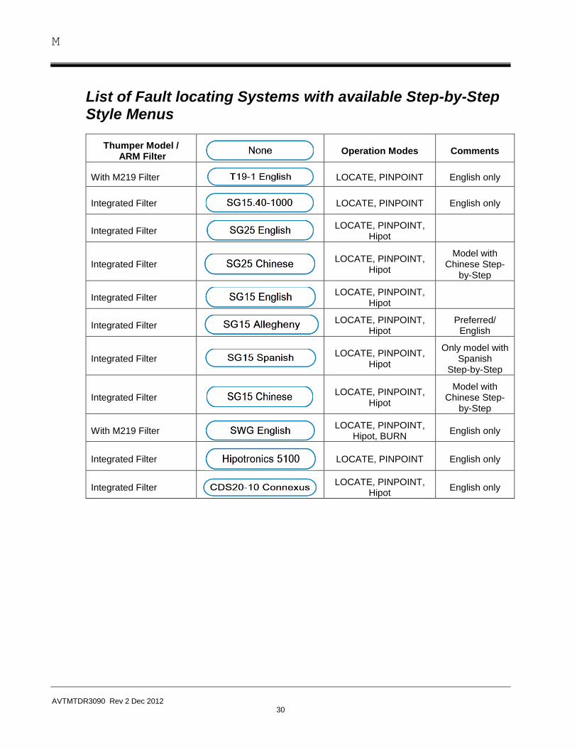
List of Fault locating Systems with available Step-by-Step Style Menus
Thumper Model / ARM Filter
Operation Modes Comments
With M219 Filter
LOCATE, PINPOINT English only
Integrated Filter
LOCATE, PINPOINT English only
Integrated Filter
LOCATE, PINPOINT, Hipot
Integrated Filter
LOCATE, PINPOINT, Hipot
Model with Chinese Step-
by-Step
Integrated Filter
LOCATE, PINPOINT, Hipot
Integrated Filter
LOCATE, PINPOINT, Hipot
Preferred/ English
Integrated Filter
LOCATE, PINPOINT, Hipot
Only model with Spanish
Step-by-Step
Integrated Filter
LOCATE, PINPOINT, Hipot
Model with Chinese Step-
by-Step
With M219 Filter
LOCATE, PINPOINT, Hipot, BURN
English only
Integrated Filter
LOCATE, PINPOINT English only
Integrated Filter
LOCATE, PINPOINT, Hipot
English only
STEP-by-STEP Style Menus
AVTMTDR3090 Rev 2 Dec 2012
31
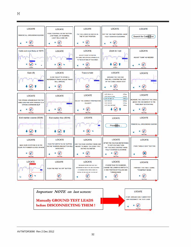
LOCATE "Arc Reflection Method" (ARM®) using
STEP-by-STEP
ARM® is today’s state of the art method to locate faults in XLPE and EPR distribution and transmission type cables. When the T3090 is used with an ARM capable fault locating system (Surge Generator plus ARM Filter, either integrated or stand-alone) for the first time, it is recommended to make use the of STEP-by-STEP style menu. It is available for all Megger systems plus a number of competitive systems.
NOTE: If no STEP-by-STEP is available or the operator prefers to not display it on the TDR screen, NONE must be selected as described under Para 2.2., page 8. If a STEP-by-STEP is selected, it should be selected for the same language as selected under the Default Settings under Para 2.2., page, provided it is available in that language, otherwise the operator might select the English files.
NOTE: In the following illustration the SG15 Allegheny Thumper Model is used
The T3090TDR is now set up to provide the “STEP-by-STEP’ style menu for fault locating in the ARM mode for the SG15-1150M unit;
Follow the red arrow from screen to screen by clicking on the control knob and make any adjustments by as prompted with rotary control knob.
M
AVTMTDR3090 Rev 2 Dec 2012
32
Important NOTE on last screen:
Manually GROUND TEST LEADS
before DISCONNECTING THEM !
STEP-by-STEP Style Menus
AVTMTDR3090 Rev 2 Dec 2012
33
Performing a Hipot Test with the SG-15 Allegheny Menu (English) in the “STEP-by-STEP” style menu
Go to main screen, select QUICK- STEPS style menu and click on HIPOT icon
NOTE: going through the Hipot procedure will test if cable will hold voltage or is faulted
Follow the red circled Step-by-Step symbol, the user is provided with one instruction at the time and will successfully finish the Hipot procedure.
Follow the red circled Step-by-Step symbol
Explanation of other symbols on screen:
By turning the Rotary Knob to the x position and clicking on it, the user will exit the Hipot procedure and go back to the main screen
By turning the Rotary Knob to the far left check mark and clicking on it, the user will be taken back to the previous step
Follow the red circled Step-by-Step symbol
M
AVTMTDR3090 Rev 2 Dec 2012
34
By Following the red circled Step-by-Step symbol, the operator will go through another 9 steps to finish the test
AVTMTDR3090 Rev 2 Dec 2012
35
7 UTILITY MENU
Software Upgrade
When a software update becomes available, the customer will receive on request a USB memory stick in order to perform the update.
Update Procedure:
1. Before powering unit up, insert USB stick
2. Power unit up
3. After booting up screen will ask, if you want to update Software, please acknowledge
4. Unit will go automatic software loading, and when finished asked to reboot unit and remove USB stick. Power unit off and wait 20 seconds, then reboot. Unit, which will then go through the update cycle (depending on the age of the old version this might take several minutes).
5. The default values are typically not affected by the upgrade, but it is recommended to verify them, especially the setting of the start marker and trigger delay.
Using radar to pre-locate faults will save time and reduce cable damage. The T 3090 is designed to be most user-friendly radar on the market! Advanced features include One Button Operation, Automatic Gain and a Large Color Screen. The T 3090 will automatically ‘read’ the cable end and display the fault distance with a single thump. Our interactive ‘Step-By-Step Easy Mode’ will help train (or re-train) the occasional user while on the job! The optional ‘Sectionalizing Mode** will quickly sectionalize faults in loops or radial systems.
Measuring Range (ft, m , m sec or NVA)
Continuously from 0 ft to 25,000 ft X Models 0 ft to 100,000 ft***
Pulse Width: Automatic with range selection or manual 50 ns, 100 ns, 200 ns, 500 ns, 1µs, 2 µs, 5 µs, 10 µs
Pulse Shape: special pulse shape for high resolution
Sampling Rate: 100 MHz
Accuracy: <= 2.5 feet depending on displayed range
Screen: High Brite 1200 nits 10.4” diagonal VGA Color TFT LC-Display,
Velocity of propagation: Via cable menu or manual between 140 ft/µs ... 492 ft/µs (also in m/µs)
Display Choices: live trace always visible, stored reference & fault trace Up to 10 superimposed traces visible on display for comparison
Weight / Dimensions: 17lbs, 11” x 15” x 6”
Operator Menu Styles:
Quick Steps® Style Menu Automatic fault distance location Automatic “short” or “open” assessment
M
AVTMTDR3090 Rev 2 Dec 2012
38
Step-by-Step Easy Style Menu
Unique real time on screen tutorial for : fault locating –hipot – pinpointing – burning for all MEGGER & some competitor’s thumpers
Expert Style Menu NOTE: user can custom configure and pass -word protect the specific TDR features available in each of the 3 menu styles (22), depending on the experience & skill level of the operator
Optional Fault locating Programs
Sectionalizing: Automatic sectionalizing in loops, identifying cable fault between 2 closest transformers
Surge Pulse: fault locating with TDR as transient recorder
Convenient Features:
PC Communication: Upgrade & Up & Download via USB Port
Power Requirements: 115 V / 230 V, 50 / 60 Hz
Operating Temperature: -5 F to 105 F (-20 °C + 40 °C)
*ARM®
is a Trademark of MEGGER Electronics, Inc. Quick Steps
® is applied for Trademark by MEGGER Electronics, Inc.
** Sectionalizing, Patent No.US 6,683,459 B2 *** Available 06/2012