10
WWW.MEGGER.COM TIME DOMAIN REFLECTOMETER - APPLICATIONS

WW
W.M
EG
GE
R.C
OM
TIME DOMAIN REFLECTOMETER - APPLICATIONS
Page 1
TIME DOM AIN RE FLEC TOMETER - APPLIC ATIONS
Telephone
Testing In the Work Center
As with any test equipment, it is best to learn about the equipment in a controlled environment by simulating some known faults before going into the field and having to interpret the information under the pressure or having to get the cable back on line. A word of caution: MAKE SURE THE PROBLEMS ARE REAL WORLD! Physical problems such as opens, shorts, load coils and bridged taps are easy to duplicate. Water in the cable is harder to duplicate. What does a water problem really look like?
In the real world, when water causes a problem in the cable, it takes place over a long period of time. Also, the water by itself is not the problem. It is the contamination (for example, salt from the ground and air) that the water is carrying that causes the problem. To simulate the water-in-the-cable problem, make a hole in the cable and immerse the cable in water. To simulate the salts in the ground or air and to speed up the cable deterioration process, simply add some common table salt to the water. Now, using the TDR, it is possible to see what water in the cable really looks like.
Another example of modeling a field problem in the shop is to test across the pair with an Ohmmeter. A reading of less than 100 K Ohms indicates a bad pair. A TDR connected to this pair will usually find the problem. However, if you try to simulate this problem in the shop by simply connecting a 100 K Ohm resistor across a pair, the TDR will not find the 100 K Ohm resistor. Why not?
The field pair with the low resistance will also have a change in impedance caused by moisture in the cable. The Ohmmeter is looking only at the resistance; the TDR is looking at the total cable impedance. The total cable impedance includes the resistance, the capacitance, and the inductance. The whole cable and the whole fault are included in the impedance. To simulate the fault with just a resistor is not simulating the whole fault. It will not tell you the quality of the cable or how far away the problem is. A TDR will. Therefore, when simulating a field problem in the shop, make certain the whole problem (or model) is simulated.
Moisture in Twisted Pair
Scenario: A rural telephone subscriber complained of a noisy telephone line. The noise is traced to the drop. The subscriber has a 2,800 foot two-pair drop to the home, along a country road ditch, through the yard, and into the house. The unused pair is found to be quieter so the customer is switched to the quieter pair. The problem appears to be solved; for now. A few months later, the customer started complaining again!
NOTES
Page 2
TIME DOM AIN RE FLEC TOMETER - APPLIC ATIONS
Basic tests are once again conducted on the pairs and the original pair now appears quieter. This is a common problem experienced when water gets into a cable; noisy pairs going quiet and quiet pairs becoming noisy.
A large percentage of twisted pair problems fall within the moisture-in-the-cable category. How to locate the problem, why one pair may be affected but not another, and how much of the cable is affected are all problems you have to address.
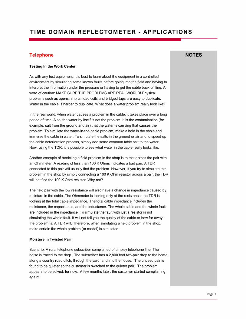
A TDR will find water in the cable. It shows up as a lowering of the cable impedance. Most times, though, it is not possible to accurately tell how wide the water problem is. In filled cable, moisture cannot migrate inside the cable so it is always a point problem. In air-core or pulp cable, moisture can migrate anywhere along the cable.
Figure 1: Water in the cable (example)
By testing the cable from both ends and recording the distance to fault in all pairs, it is possible to determine approximately how wide the problem is.
When testing through water, measurements up to the water are very accurate. After the water, distance readings may be erroneous due to a change in the VF (velocity factor) caused by the water. Even though the moisture may be 20 or 30 feet wide, each pair usually becomes impregnated at different points. The range of these points will indicate the length of the problem.
Water can seep into the conductors through pin holes in the plastic insulator around the conductors. Water in a multi-paired, air-core cable may be several feet wide. When testing each pair, the footage to the problem may read different for each pair. This is because the water has penetrated through the conductor insulation at different points and shorted out the conductors at different footages.
After performing TDR tests on the pairs the location and how wide the water damage ranges is now known. But it is still necessary to locate where the water actually entered the cable. The break in the sheath will not necessarily be within the span of where the water is found and will not necessarily show up in the testing. If the break in the sheath of the cable is not fixed, the problem will show up again in the future.
If the hole in the sheath happens to be at a high point in the cable, the water will enter
NOTES
Page 3
TIME DOM AIN RE FLEC TOMETER - APPLIC ATIONS
through the hole then migrate to a lower point. If the water entry point is not found, it may be necessary to visually inspect the cable. It is also necessary to check the integrity of the sheath.
Locating Bridged Taps
A bridged tap is a component within a telephone system that can be one of the easiest things to locate with a TDR. It can also be one of the most incorrectly identified components.
The definition of a bridged tap itself can often cause confusion. Some people refer to a bridged tap as the lateral which extends off of a main cable circuit. However, the true definition of a bridged tap is the point on the cable where a lateral connects to the main cable.
A bridged tap is not a section of cable. Therefore, we will refer to the point of connection of the lateral to the main cable as the bridged tap. The cable extending from the bridged tap to the subscriber will be referred to as the lateral.
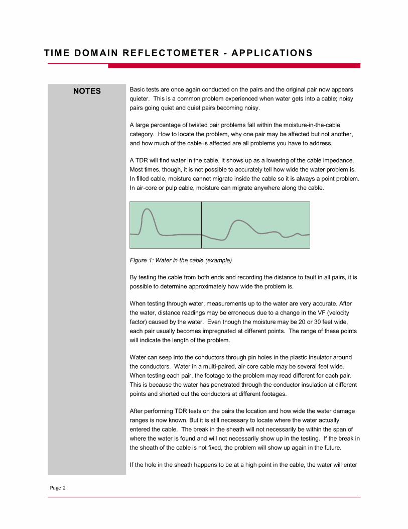
Figure 2: Bridged Tap (example)
Figure 2 is a common waveform which results from testing a section of cable containing a bridged tap from which a lateral extends to the subscriber.
Referring to Figure 2, a person reviewing the waveform might assume the following.
Point A: The TDR's pulse from the point of connection. Point B: (downward reflection) The point of a bridged tap on the main cable. Point C: The end of the lateral. Point D: The end of the main cable circuit.
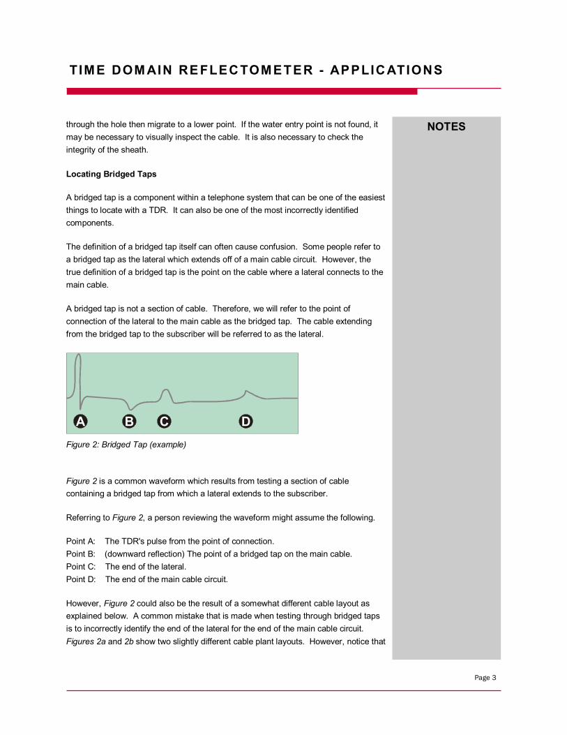
However, Figure 2 could also be the result of a somewhat different cable layout as explained below. A common mistake that is made when testing through bridged taps is to incorrectly identify the end of the lateral for the end of the main cable circuit. Figures 2a and 2b show two slightly different cable plant layouts. However, notice that
A B C D
NOTES
Page 4
TIME DOM AIN RE FLEC TOMETER - APPLIC ATIONS
the resulting waveforms are identical.
Figure 2a Figure 2b
In Figure 2a, the length of the lateral is shorter than the end of the main cable circuit. In Figure 2b, the length of the lateral is longer than the main cable circuit.
LESSON: DO NOT ASSUME THE FIRST UPWARD REFLECTION AFTER A BRIDGED TAP IS ALWAYS THE END OF THE LATERAL; IT MAY BE THE END OF THE CABLE.
It is always a good idea to refer to plant maps whenever possible to help minimize confusion or errors when testing cable plant, especially when testing through bridged taps.
Remember, a TDR will test through a bridged tap displaying a waveform interpretation of the cable under test, including any bridged taps and their corresponding laterals. A lot of information is displayed in the waveform. Therefore, a thorough study of the waveform and correct cursor placement becomes very important.
Locating Splits and Re-splits
A split or re-split pair is when one conductor, each of two different pairs are switched somewhere along the cable length. A TDR used in the traditional mode of simply looking for the impedance discontinuity can, many times, find this split. The problem with the traditional method is the discontinuity is relatively small and, therefore, the TDR's reflection will be small. If the split is relatively close, then there is no problem seeing the split. If, on the other hand, the split is some distance away, the small reflection is attenuated by cable length and the split is hard to find.
A B C D
A B
C
D
A B C D
A B C
D
NOTES
Page 5
TIME DOM AIN RE FLEC TOMETER - APPLIC ATIONS
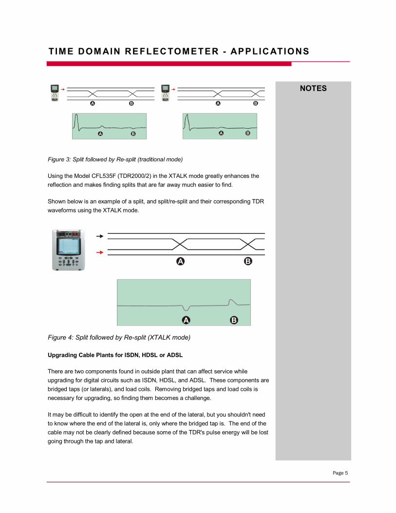
Figure 3: Split followed by Re-split (traditional mode)
Using the Model CFL535F (TDR2000/2) in the XTALK mode greatly enhances the reflection and makes finding splits that are far away much easier to find.
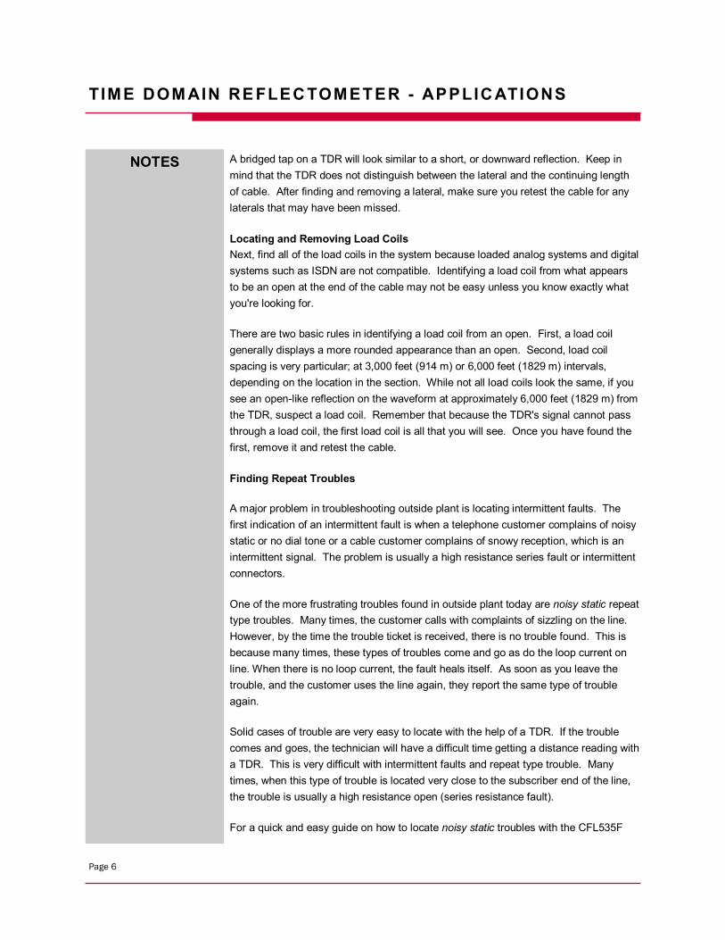
Shown below is an example of a split, and split/re-split and their corresponding TDR waveforms using the XTALK mode.
Figure 4: Split followed by Re-split (XTALK mode)
Upgrading Cable Plants for ISDN, HDSL or ADSL
There are two components found in outside plant that can affect service while upgrading for digital circuits such as ISDN, HDSL, and ADSL. These components are bridged taps (or laterals), and load coils. Removing bridged taps and load coils is necessary for upgrading, so finding them becomes a challenge.
It may be difficult to identify the open at the end of the lateral, but you shouldn't need to know where the end of the lateral is, only where the bridged tap is. The end of the cable may not be clearly defined because some of the TDR's pulse energy will be lost going through the tap and lateral.
A B
A B
A B
A B
A B
A B
NOTES
Page 6
TIME DOM AIN RE FLEC TOMETER - APPLIC ATIONS
A bridged tap on a TDR will look similar to a short, or downward reflection. Keep in mind that the TDR does not distinguish between the lateral and the continuing length of cable. After finding and removing a lateral, make sure you retest the cable for any laterals that may have been missed.
Locating and Removing Load Coils Next, find all of the load coils in the system because loaded analog systems and digital systems such as ISDN are not compatible. Identifying a load coil from what appears to be an open at the end of the cable may not be easy unless you know exactly what you're looking for.
There are two basic rules in identifying a load coil from an open. First, a load coil generally displays a more rounded appearance than an open. Second, load coil spacing is very particular; at 3,000 feet (914 m) or 6,000 feet (1829 m) intervals, depending on the location in the section. While not all load coils look the same, if you see an open-like reflection on the waveform at approximately 6,000 feet (1829 m) from the TDR, suspect a load coil. Remember that because the TDR's signal cannot pass through a load coil, the first load coil is all that you will see. Once you have found the first, remove it and retest the cable.
Finding Repeat Troubles
A major problem in troubleshooting outside plant is locating intermittent faults. The first indication of an intermittent fault is when a telephone customer complains of noisy static or no dial tone or a cable customer complains of snowy reception, which is an intermittent signal. The problem is usually a high resistance series fault or intermittent connectors.
One of the more frustrating troubles found in outside plant today are noisy static repeat type troubles. Many times, the customer calls with complaints of sizzling on the line. However, by the time the trouble ticket is received, there is no trouble found. This is because many times, these types of troubles come and go as do the loop current on line. When there is no loop current, the fault heals itself. As soon as you leave the trouble, and the customer uses the line again, they report the same type of trouble again.
Solid cases of trouble are very easy to locate with the help of a TDR. If the trouble comes and goes, the technician will have a difficult time getting a distance reading with a TDR. This is very difficult with intermittent faults and repeat type trouble. Many times, when this type of trouble is located very close to the subscriber end of the line, the trouble is usually a high resistance open (series resistance fault).
For a quick and easy guide on how to locate noisy static troubles with the CFL535F
NOTES
Page 7
TIME DOM AIN RE FLEC TOMETER - APPLIC ATIONS
(TDR2000/2) refer to the following:
1. Disconnect at the protector on the subscriber end.
2. Confirm the trouble. Connect a butt set, turn the speaker on and listen to the line. Confirm that the trouble you hear (if any) is what the customer reported, and not a separate case of trouble.
3. Turn the butt set to mute, and dial the silent termination. This is done to prevent any noise picked up by the microphone of the butt set to be put on the line. It may affect the TDR waveform.
4. Connect the CFL535F (TDR2000/2). Connect the test probe leads to the pair under test. Continue to keep the butt set connected to the pair with the silent termination.
5. Switch on the TDR by touching the POWER key.
6. Initiate the Intermittent Fault Locate mode.
7. Wait for the fault to occur. With the loop current on line, the trouble will normally appear within 5 to 10 minutes.
Cellular
The TDR can be a very useful tool when turning-up a new cell site. Within a single cell there may be as many as six antenna cables with multiple transmit antenna cables and multiple receive antenna cables.
During installation, it is possible that the cables can become mixed up. Installers are usually more intent on safely making all the right mechanical connections, rather than making sure the cables are connected to the proper antennas. On the other hand, the site operator is very interested in the accuracy of matching cables to antennas.
Graphic style TDRs can easily distinguish between receive antenna cables and transmit antenna cables. With the noise filter turned off, connect the TDR to the transmission cable with an antenna in place, zoom in and study the waveform. A very noisy waveform will be seen. The RF signal from the antenna will show up on the TDR baseline as noise. A relatively high gain antenna, such as the receive antenna, will have more signal amplitude than a relatively low gain transmit antenna. This difference in amplitude allows distinction between receive antennas and transmit antennas and makes sure they are not mislabeled and swapped.
NOTES
Page 8
TIME DOM AIN RE FLEC TOMETER - APPLIC ATIONS
If it is necessary to see the actual waveform of the cable under test even with the antenna connected, simply turn the instrument on and activate TDR's noise filter. The TDR's noise filter will remove most of the RF signal even in a relatively high RF energy level environment.
NOTES
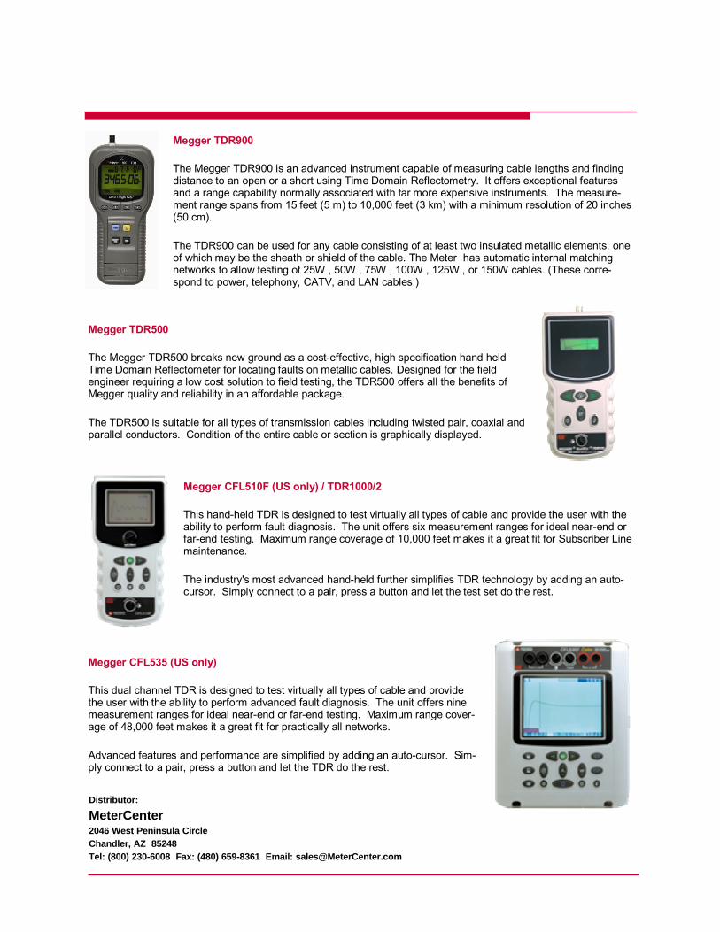
Megger TDR900
The Megger TDR900 is an advanced instrument capable of measuring cable lengths and finding distance to an open or a short using Time Domain Reflectometry. It offers exceptional features and a range capability normally associated with far more expensive instruments. The measure-ment range spans from 15 feet (5 m) to 10,000 feet (3 km) with a minimum resolution of 20 inches (50 cm).
The TDR900 can be used for any cable consisting of at least two insulated metallic elements, one of which may be the sheath or shield of the cable. The Meter has automatic internal matching networks to allow testing of 25W , 50W , 75W , 100W , 125W , or 150W cables. (These corre-spond to power, telephony, CATV, and LAN cables.)
Megger TDR500
The Megger TDR500 breaks new ground as a cost-effective, high specification hand held Time Domain Reflectometer for locating faults on metallic cables. Designed for the field engineer requiring a low cost solution to field testing, the TDR500 offers all the benefits of Megger quality and reliability in an affordable package.
The TDR500 is suitable for all types of transmission cables including twisted pair, coaxial and parallel conductors. Condition of the entire cable or section is graphically displayed.
Megger CFL510F (US only) / TDR1000/2
This hand-held TDR is designed to test virtually all types of cable and provide the user with the ability to perform fault diagnosis. The unit offers six measurement ranges for ideal near-end or far-end testing. Maximum range coverage of 10,000 feet makes it a great fit for Subscriber Line maintenance.
The industry's most advanced hand-held further simplifies TDR technology by adding an auto-cursor. Simply connect to a pair, press a button and let the test set do the rest.
Megger CFL535 (US only)
This dual channel TDR is designed to test virtually all types of cable and provide the user with the ability to perform advanced fault diagnosis. The unit offers nine measurement ranges for ideal near-end or far-end testing. Maximum range cover-age of 48,000 feet makes it a great fit for practically all networks.
Advanced features and performance are simplified by adding an auto-cursor. Sim-ply connect to a pair, press a button and let the TDR do the rest.
Distributor:
MeterCenter 2046 West Peninsula Circle Chandler, AZ 85248 Tel: (800) 230-6008 Fax: (480) 659-8361 Email: [email protected]


