22
EN Instruction Manual Fusion Plate Heat Exchangers AlfaNova 76 AlfaNova 400 Part number 34562191-01 0903

EN
Instruction ManualFusion Plate Heat Exchangers
AlfaNova 76AlfaNova 400
Part number 34562191-010903


Table of contents English
Fusion Plate Heat Exchanger EN
EN
Table of contents
Description ........................................................................................ 1Definitions .................................................................................. 1Main components ...................................................................... 2Name plate ................................................................................ 3Function ..................................................................................... 5AlfaFusion technology ............................................................... 6
Installation ......................................................................................... 7Requirements ............................................................................ 7Installation as evaporator........................................................... 8Installation, welding aspects ...................................................... 8Lifting ......................................................................................... 9
Operation ......................................................................................... 10Start-up .................................................................................... 10Unit in operation....................................................................... 11Shut-down................................................................................ 12
Maintenance .................................................................................... 13General guidelines regarding maintenance ............................. 13Cleaning-In-Place (CIP)........................................................... 14
Fault-tracing .................................................................................... 15Pressure drop problems .......................................................... 15Heat transfer problems ............................................................ 16
Except for this Instruction Manual, the following document is also included in this shipment:
– Declaration of Conformity.
How to contact Alfa Laval:
Contact details for all countries are continually updated on our website.
Please visit www.alfalaval.com and contact your local Alfa Laval Representative.

English Environmental compliance
Fusion Plate Heat ExchangerEN
EN
Environmental compliance
AlfaLaval endeavours to perform its own oper-ations as cleanly and efficiently as possible, and to take environmental aspects into con-siderattion when developing, designing, manu-facturing, servicing and marketing its products.
UnpackingPacking material consists of wood, plastics, card-board boxes and in some cases metal straps.
• Wood and cardboard boxes can be reused, recycled or used for energy recovery.
• Plastics should be recycled or burnt at a licensed waste incineration plant.
• Metal straps should be sent for material recycling.
MaintenanceDuring maintenance oil and wear parts in the ma-chine are replaced.
• All metal parts should be sent for material recy-cling.
• Worn out or defective electronic parts should be sent to a licensed handler for material recy-cling.
• Oil and all non metal wear parts must be taken care of in agreement with local regulations.
ScrappingAt end of use, the equipment shall be recycleed according to relevant, local regulations. Beside the equipmnet itself, any hazardous residues from the process liquid must be considered and dealt with in a proper manner. When in doubt, or in absence of local regulations, please contact the local Alfa Laval sales company.

Description English
Plate Heat Exchanger 1EN
EN
Description
Definitions
AlfaFusion™ One-material process that results in an all-stainless steel fusion-bonded plate heat exchanger, gives joints superior to welded joints.
Connection plate Plate used to separate two or more services in one plate heat exchanger. The plate pack performing such a service is called a section.
Fusion plate heat exchanger
A number of corrugated plates and its frame bonded to a plate pack at high temperature. Figure on page 2 shows typical components of a fusion plate heat exchanger.
Heat transfer area The area of the plate, which is in contact with both fluids.
Plate A sheet of 100 % stainless steel plate pressed into a corrugated pattern and equipped with port holes for media inlet and outlet.
Plate pack An assembly of plates bonded together to an unit having internal chan-nels in which two or more fluids can be handled.
Port Inlet or outlet opening in the plates and in the cover plates. Most plates have four ports.
Total heat transfer area The total surface area of all the bonded plates, which are in contact with both fluids.

English Description
2 Plate Heat ExchangerEN
EN
Main components
WARNING! The fusion PHE must not be opened.
Support Can as an option be equipped with earth-ing lugs.
ConnectionsEquipped with carbon steel or stainless steel fittings, permitting the media to enter into the heat exchanger.
Bonded sealKeeping the media within the unit
Lifting deviceFor correct and safe lifts during transportation and installation
Cover platesFront and rear cover plates to protect the chan-nel plates and in-crease the design pressure.

Description English
Plate Heat Exchanger 3EN
EN
Name plate
On the name plate the type of unit, manufacturing number and manufacturing year can be found. Pres-sure vessel details in accordance with the applicable pressure vessel code are also stated. The name plate is fixed to the frame plate, most common, or the pressure plate.
Four nameplates, type 1–4, exist depending on the type of pressure vessel approval.Nameplate type 1, PED Standard
1. Manufacturer’s name.2. Article number.3. Type.4. Manufacturing number.5. Date of manufacture.6. Max. allowed operating temperatures.7. Max. allowed operating pressures.8. Test pressure.9. Volume of each space.
10. Operating area.11. Fluid group.12. Customer unique information.13. Bar code information.14. Space for logotype.15. Locations of connections for each fluid.16. Allowed operating temperatures and
pressures.17. Description of each space.18. *)Possible locations of connections.19. Space for mark of approval.
Nameplate type 2, PED Stainless steel, optional1. Space for logotype.2. Manufacturer's name.3. Type.4. Serial number.5. Manufacturing year.6. Fluid group.7. Locations of connections for each fluid.8. Volume of each space.9. Max. allowed operating pressures.
10. Max. allowed operating temperatures.11. Test pressure.12. Max. operating temperatures and pressures.13. Date of test pressure.14. Information unique to the customer.15. Space for mark of approval.
– CE-409 BHE Manufacturing, Ronneby, Sweden– CE-036 Alfa Laval (Jiangyin)
Manufacturing Co., Ltd., Jiangyin City, PRC– CE-0948 Alfa Laval S.p.A. Alonte, Italy.
16. *) Possible locations of connections.
*) Sketch on nameplate showing possible locations of connections depending on heat exchanger performance.
Warning!For each unit, the mechanical design pres-sures and temperatures are marked on the name plate. These must not be exceeded.
14
1234 15
6789
16
10
17
11
12 18
13
5
19
1
23456789
10111213
14
15
16

English Description
4 Plate Heat ExchangerEN
EN
Nameplate type 3, ASME1. Space for logotype.2. Space for National Board stamp and serial number3. Space for manufacturer’s name:
– CE-409 BHE Manufacturing, Ronneby, Sweden
– CE-036 Alfa Laval (Jiangyin) Manufacturing Co., Ltd., Jiangyin City, PRC
– CE-0948 Alfa Laval S.p.A. Alonte, Italy.
4. Locations of connections for each fluid.5. Max. allowed working pressures at temperature.6. Max. allowed medium temperature at max. allowed work-
ing pressure.7. Serial number.8. Manufacturing year.9. Test pressure.
10. Volume of each space.11. Type.12. Information unique to the customer.13. *) Possible locations of connections.
Nameplate type 4, PED Customer designed, optional
1. Article number.2. Type.3. Manufacturing number.4. Date of manufacture.5. Max. allowed operating temperatures.6. Max. allowed operating pressures.7. Test pressure.8. Volume of each space.9. Fluid group.
10. Customer unique information.11. Customer unique information.12. Space for logotype.13. Manufacturer’s name.14. Locations of connections for each fluid.15. Customer unique information.16. Space for mark of approval.
*) Sketch on nameplate showing possible locations of connections depending on heat exchanger execution.
12
3
45
6
7
89
1011
12 13
1234
56789
10
11
12
13
14
15
16

Description English
Plate Heat Exchanger 5EN
EN
Function
The fusion plate heat exchangers consist of a pack of bonded corrugated metal plates with ports for the passage of the two fluids between which heat trans-fer will take place.
The media in the heat transfer are led into the bond-ed plate pack through portholes at the corners and are distributed into the passages between the bond-ed, corrugated plates.
The heating surface consists of thin corrugated plates stacked on top of each other. In the fusion process at high temperature channels are formed between the plates and corner ports are arranged so that the two media flow through alternate chan-nels, always in counter-current flow. The contact points are also bonded to withstand the pressure of the media handled.
The fusion plate heat exchanger is typically used for heating or cooling media with low to medium viscosity. A specific fusion plate heat exchanger is dimensioned for a specific duty, set out in the product documentation, and should not be used in any other way without consulting the supplier.
Bonded sealKeeping the media within the unit.Bonded corrugated
plates for media flow in alternate channels.
Cover platesFront and rear cover plates to protect the channel plates and increase the design pressure.

English Description
6 Plate Heat ExchangerEN
EN
AlfaFusion technology
Fusion-bonded plate heat exchangers represent a new class of plate heat exchangers made of 100 % stainless steel.
AlfaNova comprises a number of thin corrugated stainless steel plates. The process uses a stain-less steel filler as activator to bond the plates to-gether in a high temperature furnace. At contact points between the corrugated plates the filler re-acts with the plate surface. The filler has a very good capability to wet surfaces and fill crevices.
It has almost full interaction with the plates and a fu-sion zone is created. This zone is in consequence also of stainless steel and has similar properties to the plates in terms of corrosion resistance and dura-bility.
AlfaFusion technology enables the production of reli-able heat plate exchangers with higher mechanical and termal resistance than those of conventional technology.
Cover plate
Corrugated plates bonded together with stainless steel filler forming chan-nels between the plates.
Cover plate

Installation English
Plate Heat Exchanger 7EN
EN
InstallationRequirements
WARNING! The fusion PHE must not be opened.
Installation in general
The installation must be provided with equipment that protects the heat exchanger against pressures and temperatures outside the approved minimum and maximum values shown on the nameplate.
For best possible heat transfer performance, the heat exchanger should be connected so that the me-dia flow through the heat exchanger in opposite di-rections (in counter-flow). Take into account the risk of fire during the installation work, i.e. bear in mind the distance to flammable substances.
Warning!The heat exchanger must be installed and operated in such a manner that no risk of injury to personnel and damage to proper-ty will be incurred.
Note!Unless otherwise specified, product data for normal refrigerants, i.e. HFC and HCFC, are applicable to refrigeration applications. The manufacturer must be specifically con-sulted before the heat exchanger is used for flammable, toxic or dangerous liquids (e.g. hydrocarbons). The use must follow the relevant safety rules for handling such liquids. For further information, please refer to the Internet site of the supplier.
Warning!Safety valves should be installed according to pressure vessel regulations.
Note!Before connecting any piping, make sure all foreign objects have been flushed out of the system.
FoundationInstall on a flat foun-dation giving enough support to the unit.
Protection against pipe forcesFit the pipes so that no tension is transferred to the heat exchanger.
Protection against overheatingProtect the heat ex-changer by using a heat-sink (welding paste or tape) around the connection before welding operation.

English Installation
8 Plate Heat ExchangerEN
EN
Installation as evaporatorFor refrigeration applications – figure A below shows the installation of an evaporator, for which the connections may be either on the front or on the rear. In evaporator applications and in applica-tions in which a phase change of media occurs, the heat exchanger should be installed vertically. Figure B shows a condenser.
• Use an anti-freeze thermostat and flow monitor to ensure a constant water flow before, during and after the compressor has been running.
• Avoid “pump-down”, i.e. emptying the evapora-tor by running the compressor after shut-down until a preset refrigerant pressure is reached. The temperature could then drop below the brine freezing point, which could damage the evaporator.
• Use a flow switch and a low-pressure switch.
Installation, welding aspectsFor installation of AlfaNova equipped with welding connections, TIG or MIG welding method must be used for installation of the heat exchanger to min-imize heat impact of the heat exchanger.
A
B
Note!To avoid damage due to freezing, the medium used must include an anti-freeze agent at operating conditions be-low 5 °C/41 °F and/or when the evapo-rating temperature is below 1 °C/34 °F.
Note!Protect the heat exchanger by using a heat-sink (welding paste or tape) around the connection before welding opera-tion.

Installation English
Plate Heat Exchanger 9EN
EN
Lifting
Warning!Never lift by the connections or the studs around them. Straps should be used when lifting. Place straps according to picture.
AlfaNova 76
AlfaNova 400

English Operation
10 Plate Heat ExchangerEN
EN
OperationStart-up
Check that the valve is closed between the pump and the unit controlling the system flow rate.
If there is a valve at the exit make sure that it is fully open.
Open the vent and start the pump.
Open the valve slowly.
When all air is expelled, close the vent.
Repeat steps 1–5 for the second medium.
Note!If several pumps are included in the sys-tem, make sure you know which one should be activated first.
Note!Adjustments of flow rates should be made slowly in order to avoid the risk of water hammer.Water hammer is a short-lasting pres-sure peak that can appear during start-up or shut-down of a system, causing liquids to travel along a pipe as a wave at the speed of sound. This can cause considerable damage to the equipment.
1
Closed
Open
Closed
Open Closed
2
3Open
4
Openslowly
5Close
6

Operation English
Plate Heat Exchanger 11EN
EN
Unit in operation
During operation, check that
media temperatures and pressures are within the limits stated on the name plate
no leakages appear due to faulty tightening of the connections.
Protection against freezingBear in mind the risk of freezing at low temperatures. Heat exchangers that are not in operation should be emptied and blown dry whenever there is risk of freezing.
Protection against cloggingUse a filter as protection against the possible occur-rence of foreign particles. If you have any doubt con-cerning the maximum particle size, consult your nearest representative of the supplier or look under Product information at the supplier's Internet site.
Protection against thermal or/and pressure fatigueSudden temperature and pressure changes could cause fatigue damage to the heat exchanger. There-fore, following must be taken into consideration to ensure that the heat exchanger operates without swinging pressures/temperatures.
• Locate the temperature sensor as close as possi-ble to the outlet from the heat exchanger.
• Choose valves and regulation equipment which give stable temperatures/pressures for the heat exchanger.
• To avoid water hammer, quick-closing valves must not be used, e.g. on/off valves.
• In automated installations, the stopping and start-ing of pumps and actuation of valves should be programmed so that the resulting amplitude and frequency of the pressure variation will be as low as possible.
Protection against corrosionAll components in contact with media are manufac-tured in stainless steel grade AISI 316.
Media causing corrosion to AISI 316 must not be ex-posed to the heat exchanger.
InsulationHeating and cooling insulations are available as ac-cessories.
Note!Adjustments of flow rates should be made slowly in order to protect the system against sudden and extreme variations of tempera-ture and pressure.
Note!To avoid damage due to freezing, the medium used must include an anti-freeze agent at operating conditions be-low 5 °C/41 °F and/or when the evapo-rating temperature is below 1 °C/34 °F.

English Operation
12 Plate Heat ExchangerEN
EN
Shut-down
Slowly reduce the flow rate in order to avoid water hammer.
When the valve is closed, stop the pump.
Repeat steps 1–2 for the other medium/media.
If the fusion plate heat exchanger is shut down for a longer period, it should be drained.
Draining should also be done if the pro-cess is shut down and the ambient temperature is below freezing temperature of the media.
Depending on the media processed, it is also recommended to rinse and dry the heat exchanger and its connections.
Note!If several pumps are included in the sys-tem, make sure you know which one should be stopped first.
1
2
3
4

Maintenance English
Plate Heat Exchanger 13EN
EN
Maintenance
General guidelines regarding maintenance
Plate Sheet material
Also stainless steel can corrode. Chlorine ions are hazardous.
Avoid cooling brines containing chloride salts as NaCI and, most harmful, CaCI2.
Chlorine as a growth inhibitor
In every case where chlorination of AlfaNova heat exchanger cannot be avoided, your local representa-tive must be consulted.
Note!Rinse well!
Note!Under no circumstances should Hydrochlo-ric acid be used with stainless steel plates.
Water of more than 300 ppm Cl ions may not be used for preparation of cleaning solutions.
Note!Chlorine, commonly used as growth inhibi-tor in cooling water systems, reduces the corrosion resistance of stainless steels.
Chlorine weakens the protection layer of these steels making them more susceptible to corrosion attacks than they otherwise should be. It is a matter of time of exposure and concentration.

English Maintenance
14 Plate Heat ExchangerEN
EN
Cleaning-In-Place (CIP)
The Cleaning-In-Place (CIP) equipment permits cleaning of the plate heat exchanger.
CIP performs
• cleaning of fouling and descaling of lime deposits
• passivation of cleaned surfaces to reduce sus-ceptibility to corrosion
• neutralization of cleaning liquids before drain-ing.
Follow the instructions of the CIP equipment.
The following CIP models can be used: CIP200L, CIP400L and CIP800L.
Cleaning liquid Description
AlfaCaus A strong alkaline liquid, for removing paint, fat, oil and biological depos-its.
AlfaPhos An acid cleaning liquid for removing metallic oxides, rust, lime and other inorganic scale. Includes an inhibitor for passivation.
AlfaNeutra A strong alkaline liquid for neutralization of AlfaPhos before drainage.
Kalklöser P An acidic cleaning powder with a corrosion inhibitor particularly effective for removing of calcium carbonate and other inorganic scale.
Neutra P An alkaline powder for neutralization of used Kalklöser P prior to dis-posal.
AlfaAdd A neutral cleaning strengthener to be used with AlfaPhos, AlfaCaus and Kalklöser P. Provides better cleaning results on oily, fatty surfaces and where biological growth occurs. AlfaAdd also reduces any foaming.
Alpacon Descalant An acidic, water based, non-hazardous cleaning agent designed for removal of scale, magnetite, algae, humus, mussels, shellfish, lime and rust. Containing BIOGEN ACTIVE, a biological mixture made from renewable materials, as an active ingredient.
Alpacon Degreaser A neutral degreaser to be used with Alpacon Descalant. Effectively removes oil, fat or grease layers, but also reduces foaming. Containing BIOGEN ACTIVE, a biological mixture made from renewable materials, as an active ingredient.
Fault-tracing English
Plate Heat Exchanger 15EN
EN
Fault-tracingPressure drop problems
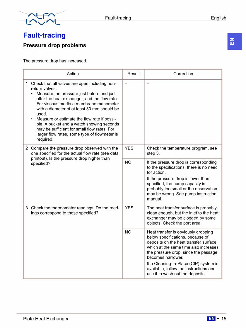
The pressure drop has increased.
Action Result Correction
1 Check that all valves are open including non-return valves.• Measure the pressure just before and just
after the heat exchanger, and the flow rate. For viscous media a membrane manometer with a diameter of at least 30 mm should be used.
• Measure or estimate the flow rate if possi-ble. A bucket and a watch showing seconds may be sufficient for small flow rates. For larger flow rates, some type of flowmeter is required.
– –
2 Compare the pressure drop observed with the one specified for the actual flow rate (see data printout). Is the pressure drop higher than specified?
YES Check the temperature program, see step 3.
NO If the pressure drop is corresponding to the specifications, there is no need for action.If the pressure drop is lower than specified, the pump capacity is probably too small or the observation may be wrong. See pump instruction manual.
3 Check the thermometer readings. Do the read-ings correspond to those specified?
YES The heat transfer surface is probably clean enough, but the inlet to the heat exchanger may be clogged by some objects. Check the port area.
NO Heat transfer is obviously dropping below specifications, because of deposits on the heat transfer surface, which at the same time also increases the pressure drop, since the passage becomes narrower.If a Cleaning-In-Place (CIP) system is available, follow the instructions and use it to wash out the deposits.

English Fault-tracing
16 Plate Heat ExchangerEN
EN
Heat transfer problems
The heat transfer capacity is dropping.
Action Result Correction
Measure temperatures at inlets and outlets. Also measure flow rates on both media, if possible. At least on one of the media, both temperatures and the flow rate must be measured.
• Check to see if the transferred amount of heat energy corresponds to the specifica-tions.
• If great precision is important, it will be necessary to use laboratory thermometers with an accuracy of 0.1 °C, and also to use the best equipment available for flow measurement.
Has the heat transfer capacity of the unit dropped below specified values?
YES Clean the heat transfer surface. Use the Cleaning-In-Place (CIP) system.
NO –


![Alfa Laval Culturefuge 400 B · Alfa Laval is a trademark registered and owned by Alfa Laval Corporate AB. [Product name] is a trademark owned by Alfa Laval Corporate AB. PCHS00142EN](https://static.documents.pub/doc/80x56/5e71a377bc5a292f26773958/alfa-laval-culturefuge-400-b-alfa-laval-is-a-trademark-registered-and-owned-by-alfa.jpg)


