80


INSTRUCTION MANUALNotes on Tuning and Maintenance of Ibis Bicycles : Rev. I
Reprinting Permitted if Source Quoted

2
This Set-Up Guide will help you with assembly tips, get you started on adjusting the suspension, maintaining your frame and explain how to perform basic mechanical jobs.
This guide does not attempt to address full bike assembly, fitting, brake and shifting set-up, riding techniques etc. Please utilize a professional level service for these items to get the best performance and enjoyment from your Ibis.
This Set-Up Guide is also available online with enhanced functions and additional information: https://www.ibiscycles.com/support/ set-up_guide
Information on legacy Ibis models available at: http://www.ibiscycles.com/bikes/ past_models
SALUTATIONSIN
TRO
DU
CTIO
N

3
CONTENTS
INTRODUCTION 2
BUILD Geometry / Quick Specs 4-6 Frame Sizing Guide 8-9 Bike Set-Up Tips and Tricks 10-37
RIDE Fork Set-Up 38-45Fork Air Pressure Charts 44Rear Shock Set-Up 46-51Rear Shock Air Pressure Charts 50-51
MAINTAIN Bearing Maintenance and Replacement 52-53 Frame Hardware 54-57 (Part Numbers and Exploded Views) Torque Specs 58-59Swingarm Removal 60-67
WARRANTY/REGISTRATION Warranty 68Serial Number 68Documentation 69
EXTRAS Chuck’s Recipe 70Contact Info 71 Index with Video Links 72-73
INTRO
DU
CTION

4
GEOMETRY / QUICK SPECS
C
SIZE SMALL MEDIUM LARGE X-LARGE
SEATTUBE A 14.5” 14.5” 16.5 18.5”TOPTUBE B 573mm 602mm 632mm 655mmHEADTUBE C 90mm 100mm 110mm 120mmCHAINSTAY D 435mm 435mm 435mm 435mmSEAT ANGLE E 77° 76° 76° 76°HEAD ANGLE F 65.9° 65.9° 65.9° 65.9°WHEELBASE G 1177mm 1197mm 1228mm 1256mmSTACK 613mm 623mm 632mm 641mmREACH 431mm 447mm 471mm 495mm
SIZE SMALL MEDIUM LARGE X-LARGE
SEATTUBE A 15.2” 16.5” 18.5” 20.5”TOPTUBE B 546mm 600mm 619mm 640mmHEADTUBE C 77.5mm 93mm 102mm 107mmCHAINSTAY D 17.5” 17.5” 17.5” 17.5”SEAT ANGLE E 75° 73° 73° 73°HEAD ANGLE F 67.5° 67.5° 67.5° 67.5°WHEELBASE G 1144mm 1140mm 1167mm 1187mmSTACK 605mm 619mm 625mm 632mmREACH 383mm 411mm 428mm 448mm
RIPMO RIPLEY LS
• 29” wheels• 145mm rear wheel dw-link travel• Approved for 160mm forks, 44mm rake
is STRONGLY recommended• 65.9º head angle with a 160mm fork• Cable routing through continuous internal tubes• Chainstay length: 17.1”• Threaded bottom bracket (73mm English thread)• ISCG 05 compatible with optional removable adapter • Tapered headtube and steerer: ZS44 upper, ZS56 lower• 12 x 148mm BOOST rear axle • 160mm post mount
• 29” wheels• 120mm rear wheel dw-link travel• Approved for 120-140mm forks, 51mm rake
is STRONGLY recommended• 67.5º head angle with a 130mm fork• Super versatile internal cable routing• Chainstay length: 17.5”• Threaded bottom bracket (73mm English thread)• Shimano side swing front derailleur compatible• Tapered headtube and steerer: ZS44 upper, EC49 lower• 12 x 148mm BOOST rear axle • 160mm post mount
BU
ILD
5
GEOMETRY / QUICK SPECS
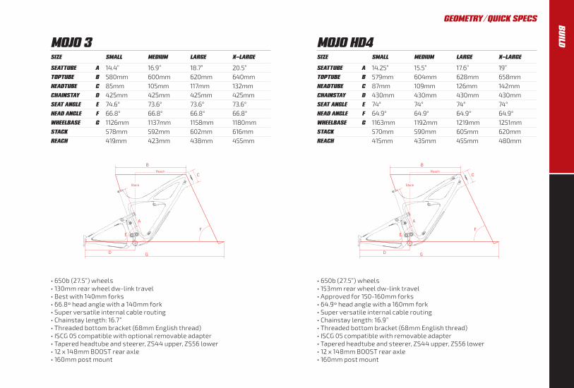
MOJO HD4SIZE SMALL MEDIUM LARGE X-LARGE
SEATTUBE A 14.25” 15.5” 17.6” 19”TOPTUBE B 579mm 604mm 628mm 658mmHEADTUBE C 87mm 109mm 126mm 142mmCHAINSTAY D 430mm 430mm 430mm 430mmSEAT ANGLE E 74° 74° 74° 74°HEAD ANGLE F 64.9° 64.9° 64.9° 64.9°WHEELBASE G 1163mm 1192mm 1219mm 1251mmSTACK 570mm 590mm 605mm 620mmREACH 415mm 435mm 455mm 480mm
• 650b (27.5”) wheels• 153mm rear wheel dw-link travel• Approved for 150-160mm forks• 64.9º head angle with a 160mm fork• Super versatile internal cable routing• Chainstay length: 16.9”• Threaded bottom bracket (68mm English thread)• ISCG 05 compatible with removable adapter• Tapered headtube and steerer, ZS44 upper, ZS56 lower• 12 x 148mm BOOST rear axle• 160mm post mount
MOJO 3SIZE SMALL MEDIUM LARGE X-LARGE
SEATTUBE A 14.4” 16.9” 18.7” 20.5”TOPTUBE B 580mm 600mm 620mm 640mmHEADTUBE C 85mm 105mm 117mm 132mmCHAINSTAY D 425mm 425mm 425mm 425mmSEAT ANGLE E 74.6° 73.6° 73.6° 73.6°HEAD ANGLE F 66.8° 66.8° 66.8° 66.8°WHEELBASE G 1126mm 1137mm 1158mm 1180mmSTACK 578mm 592mm 602mm 616mmREACH 419mm 423mm 438mm 455mm
• 650b (27.5”) wheels • 130mm rear wheel dw-link travel • Best with 140mm forks • 66.8º head angle with a 140mm fork• Super versatile internal cable routing • Chainstay length: 16.7” • Threaded bottom bracket (68mm English thread) • ISCG 05 compatible with optional removable adapter • Tapered headtube and steerer, ZS44 upper, ZS56 lower • 12 x 148mm BOOST rear axle • 160mm post mount
BU
ILD

6
SIZE 49 53 55 58 61
SEATTUBE A 455mm 525mm 550mm 575mm 605mmTOPTUBE B 520mm 540mm 550mm 570mm 590mmHEADTUBE C 110mm 135mm 155mm 175mm 195mmCHAINSTAY D 430mm 430mm 430mm 430mm 430mmSEAT ANGLE E 74.5° 73.5° 73.5° 73.5° 73.5°HEAD ANGLE F 70.5° 71.5° 72° 72° 72°WHEELBASE G 1007mm 1011mm 1021mm 1037mm 1057mmSTACK 532mm 560mm 580mm 599mm 616mmREACH 370mm 373mm 382mm 391mm 406mmSTANDOVER 729mm 785mm 802mm 827mm 853mm
HAKKA MX
• 700c or 650b (27.5”) wheels• Trail: 67mm @ 71.5º head angle, 70mm @ 71º and 73mm @ 70.5º• Super versatile internal cable routing, Di2 compatible• T47 bottom bracket• 70mm bottom bracket drop• 700x40c BB Height: 283mm• 700x33c or 27.5x2.1” BB Height: 277mm• 34.9mm bottom pull front derailleur• Tapered headtube: IS41 upper, IS52 lower• 142x12mm rear dropout spacing• 140mm flat mount rear (160mm max rotor)
GEOMETRY / QUICK SPECSB
UIL
D

7
BU
ILD

8
MOUNTAIN BIKE SIZING GUIDE
FRAME SIZE HEIGHT / IN HEIGHT / CM
SMALL 5’0” – 5’5” 152 – 165
MEDIUM 5’4” – 5’9” 163 – 175
LARGE 5’9” – 6’2” 175 – 188
X-LARGE 6’0” – 6’6” 183 – 198
FRAME SIZING GUIDEB
UIL
D

9
HAKKA MX SIZING GUIDE
FRAME SIZE HEIGHT / IN HEIGHT / CM
49 5’0” – 5’4” 152 – 163
53 5’3” – 5’8” 160 – 173
55 5’7” – 5’11” 170 – 180
58 5’10” – 6’2” 178 – 188
61 6’1” – 6’6” 185 – 198
FRAME SIZING GUIDE BU
ILD
10
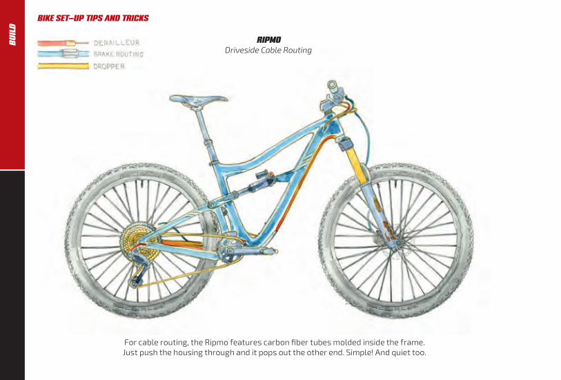
RIPMODriveside Cable Routing
BIKE SET-UP TIPS AND TRICKS
For cable routing, the Ripmo features carbon fiber tubes molded inside the frame. Just push the housing through and it pops out the other end. Simple! And quiet too.
BU
ILD

11
RIPMONon-Driveside Cable Routing
BIKE SET-UP TIPS & TRICKS
IMPORTANT: Before riding, check the saddle to tire clearance with the dropper post fully dropped and the air out of the shock with frame compressed to bottom out.
BU
ILD
12
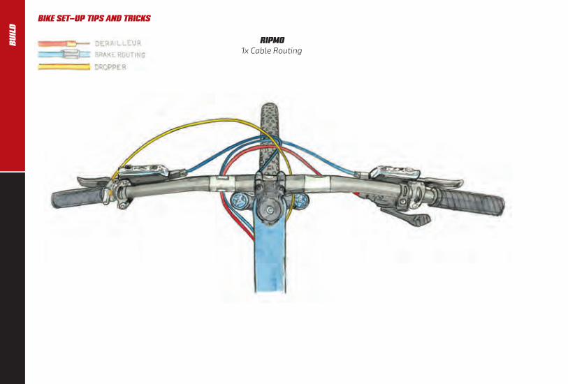
RIPMO 1x Cable Routing
BIKE SET-UP TIPS AND TRICKSB
UIL
D

13
RIPMO Front Cable Routing
BIKE SET-UP TIPS AND TRICKS BU
ILD

14
BIKE SET-UP TIPS AND TRICKS
RIPMO Driveside Cable Routing
BU
ILD

15
BIKE SET-UP TIPS AND TRICKS
RIPMO Non-Driveside Cable Routing
BU
ILD

16
BIKE SET-UP TIPS AND TRICKS
RIPMO Brake Cable Routing
BU
ILD

17
BIKE SET-UP TIPS AND TRICKS BU
ILD

18
RIPLEY LSDriveside Cable Routing
BIKE SET-UP TIPS AND TRICKSB
UIL
D

19
RIPLEY LSNon-Driveside Cable Routing
BIKE SET-UP TIPS & TRICKS BU
ILD
20
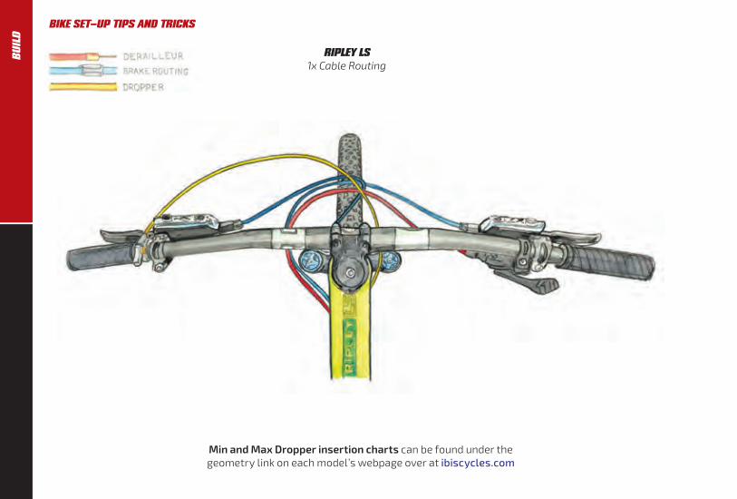
RIPLEY LS 1x Cable Routing
BIKE SET-UP TIPS AND TRICKS
Min and Max Dropper insertion charts can be found under the geometry link on each model’s webpage over at ibiscycles.com
BU
ILD
21
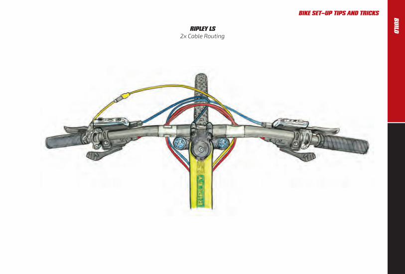
RIPLEY LS 2x Cable Routing
BIKE SET-UP TIPS AND TRICKS BU
ILD

22
A NOTE ON ROUTING RIPLEY LS AND MOJO 3 WITH TOP PULL DERAILLEURS We have made the Ripley LS, and Mojo 3 compatible with the new Shimano side swing front derailleurs. Should you be retrofitting an older style top pull derailleur to any of these frames, it is possible and here’s the recommended routing (Ripley shown, and Mojo 3, would be done similarly).
We also recommend you run both the front and rear derailleur housing a little lower between the frame and swingarm to make room for a water bottle cage.
BIKE SET-UP TIPS AND TRICKSB
UIL
D

23
CABLE ROUTING PORTS We now have plastic ports that play nicer with your cable housing. They include the most popular ones: single stop and single port, double port and double port/stop. Parts that will remain metal are single blank, single Di2, double Di2, and single Reverb port.
A NOTE FOR UK/AU/NZ/ZA FOLK AND SOME MOTORCYCLE RIDERS…
Your brake levers are most likely set up opposite to the rest of the world i.e. front brake on the right-hand side of the handlebars, and rear brake on the left-hand side.
For you folks, we recommend you route the rear brake line directly from the lever on the left-hand side of the handlebar to the left side of the down tube, attaching it using existing guides. (or cable tunnel in the case of the Ripmo). The line will have a slightly tighter radius than it would otherwise but that is OK. Be sure to leave sufficient line so the handlebars can rotate in the event of a crash. If necessary, use clear adhesive dots to prevent the line rubbing on the headtube.
Depending on the configuration of your bike, a second more complicated option may be possible if you’re not using either a front derailleur or internally routed dropper post. Route the rear brake line inside the down tube. The line enters the frame at the port on the top right of the down tube, and exits at the port on the lower left. Walk this DIY path alone, and be prepared to bleed your brakes after the cables are routed. You will also need to use our hydro line port.
BIKE SET-UP TIPS AND TRICKS
There are dozens of possible port/routing combinations on our bikes. For the latest port availability, go to our online store and search for port.http://store.ibiscycles.com
BU
ILD

24
The Mojo HD4 and Mojo 3 uses our new versatile cable port system for cable routing. We have several port styles available, depending on your drivetrain and dropper configuration.
MOJO HD4 / MOJO 3 Driveside Cable Routing
BIKE SET-UP TIPS AND TRICKSB
UIL
D

25
The most common set-up these days is a 1X drivetrain with an internally mounted dropper. We spec the Fox Transfer. We generally recommend you run your brake on the exterior, along the left side of the down tube.
MOJO HD4 / MOJO 3 Non-Driveside Cable Routing
BIKE SET-UP TIPS AND TRICKS BU
ILD
26
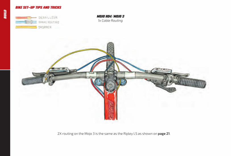
MOJO HD4 / MOJO 31x Cable Routing
2X routing on the Mojo 3 is the same as the Ripley LS as shown on page 21.
BIKE SET-UP TIPS AND TRICKSB
UIL
D

27
MOJO HD4 / MOJO 3Derailleur Cable Routing
A NOTE ON MOJO 3 ROUTING WITH TOP PULL DERAILLEURS We have made the Mojo 3 compatible with the new Shimano side swing front derailleurs. Should you be retrofitting an older style top pull derailleur refer to Ripley Routing on page 22.
BIKE SET-UP TIPS AND TRICKS BU
ILD

28
MOJO HD4 / MOJO 3Dropper Cable Routing
A NOTE ON REVERB DROPPER ROUTING
The Reverb dropper routing we prefer is not illustrated, but we’ll describe it for you. You need three of our hydro cable stops. Route the Reverb into the left side of the down tube (it’s a single port) using our hydro port. Use two other hydro ports at the bottom left side of the down tube and seattube, and fish the dropper tubing through to the seattube. Connect as normal.
If you’re using Shimano’s new side pull front derailleur, route it through the drive side of the down tube and then out at the bottom of the drive side. For top mount front derailleurs use the toptube for entry and exit for the derailleur cable. Note that you have the choice of full housing or interrupted derailleur housing with our versatile port configurations.
For droppers that use cable and housing, such as the KS LEV, route the housing according to the illustrations.
Min and Max Dropper insertion charts can be found under the geometry link on each model’s webpage over at ibiscycles.com
BIKE SET-UP TIPS AND TRICKSB
UIL
D

29
MOJO HD4 / MOJO 3Brake Cable Routing
BIKE SET-UP TIPS AND TRICKS BU
ILD

30
MOJO HD4 AND RIPMO CHAIN GUIDE For the HD4 and Ripmo we manufacture a removable ISCG 05 mount which mounts on the splines on the drive side of the bottom bracket. Standard procedures apply to mounting an ISCG 05 compatible chain guide or bash guard.
If you need an ISCG 05 adapter, it’s available in our online store: http://store.ibiscycles.com and search ISCG.
CHAIN LENGTH To determine the correct chain length: shift into the large chainring and largest cog and let all the air out of your shock (on suspension bikes only, duh).
Thread the chain through the gears and derailleurs, compress the suspension all the way to bottom out, and cut the chain at the minimum length needed with the rear derailleur stretched out.
BIKE SET-UP TIPS AND TRICKSB
UIL
D
31
BIKE SET-UP TIPS AND TRICKS BU
ILD

YES
NO
32
BIKE SET-UP TIPS AND TRICKS
NOTE ON BOOST MOJO HD4 / MOJO 3 BOTTOM BRACKET INSTALLATION The profile of the carbon swingarm on the BOOST Mojo HD4 and Mojo 3 rear triangle is wider so it interferes with the bottom bracket (BB) tool when the swingarm is in the top out position.
The BB cup on the non-drive side of the rear triangle is very close to the swingarm. When installing the BB care should be given to not scratch up or otherwise damage the frame.
We recommend using only a socket type BB installation tool from your preferred bike tool manufacturer.
On the Mojo 3, you can gain some extra room by deflating the shock and moving the swingarm to the bottom out position.
WIDE RIMS In 2014, we introduced our line of wide carbon fiber rims and wheels.
Wide rims support the tire’s sidewalls better, allowing lower pressures without the tires folding over or burping. This dramatically increases stability and traction. This shows up as faster cornering and braking, better grip in all conditions.
The low system weight of the wheels with these rims and tires combined with the monstrous traction advantage have been a revelation for those who have ridden them.
Our carbon wheels now come with the excellent Industry Nine Torch hubs. The durable hubs are made in the USA in Industry Nine’s Asheville machine shop, and feature a 60t ratchet with 6 out of phase pawls that results in a 3º engagement. They are equipped with Enduro bearings and come with either Shimano or SRAM XD drivers.
You can read all about our new rim and wheel technology at: http://www.ibiscycles.com/wheels/
PLUS TIRES The Mojo 3 and now the Mojo HD4 are compatible with the new breed of Plus tires, up to 2.8”. Combined with our ultra wide aluminum and carbon fiber rims, these tires are proving to be game-changing to those who ride them.
If you take a straw poll of the folks at Ibis, we’ve settled on 2.6” as being the sweet spot for overall performance and traction in the 27.5 and 29” wheel platforms.
The 742/942/738/938 rims are ideal for the ultra low pressures (10-18 psi) that we like to run with 2.6 and 2.8 Plus tires (or 18-25psi for 2.25” - 2.5” tires). Any of our 35mm internal width rims work incredibly well with the new Plus rubber we’ve been riding from Schwalbe, Maxxis and others.
BU
ILD

33
BIKE SET-UP TIPS AND TRICKS BU
ILD
34
BIKE SET-UP TIPS AND TRICKS
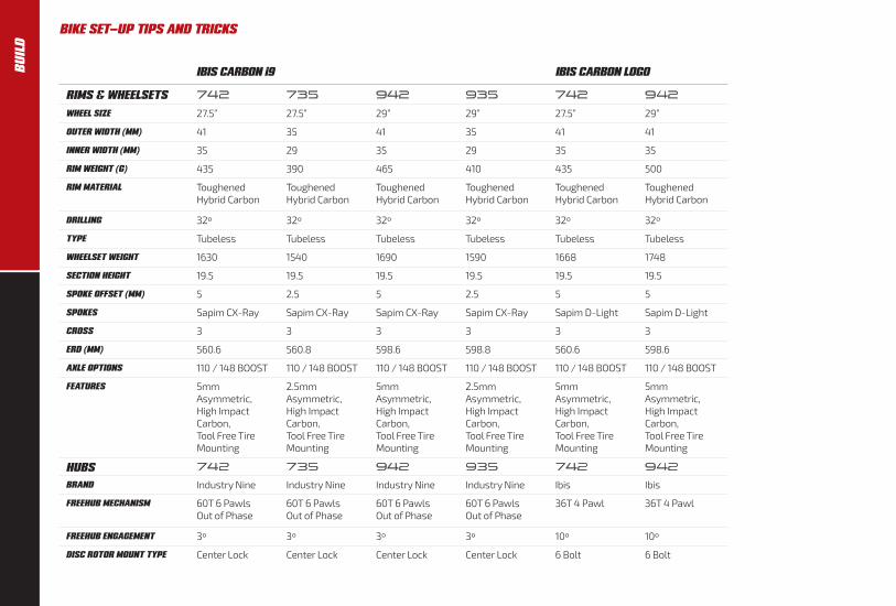
IBIS CARBON i9 IBIS CARBON LOGO
RIMS & WHEELSETS 742 735 942 935 742 942
WHEEL SIZE 27.5” 27.5” 29” 29” 27.5” 29”
OUTER WIDTH (MM) 41 35 41 35 41 41
INNER WIDTH (MM) 35 29 35 29 35 35
RIM WEIGHT (G) 435 390 465 410 435 500
RIM MATERIAL Toughened Hybrid Carbon
Toughened Hybrid Carbon
Toughened Hybrid Carbon
Toughened Hybrid Carbon
Toughened Hybrid Carbon
Toughened Hybrid Carbon
DRILLING 32º 32º 32º 32º 32º 32º
TYPE Tubeless Tubeless Tubeless Tubeless Tubeless Tubeless
WHEELSET WEIGHT 1630 1540 1690 1590 1668 1748
SECTION HEIGHT 19.5 19.5 19.5 19.5 19.5 19.5
SPOKE OFFSET (MM) 5 2.5 5 2.5 5 5
SPOKES Sapim CX-Ray Sapim CX-Ray Sapim CX-Ray Sapim CX-Ray Sapim D-Light Sapim D-Light
CROSS 3 3 3 3 3 3
ERD (MM) 560.6 560.8 598.6 598.8 560.6 598.6
AXLE OPTIONS 110 / 148 BOOST 110 / 148 BOOST 110 / 148 BOOST 110 / 148 BOOST 110 / 148 BOOST 110 / 148 BOOST
FEATURES 5mm Asymmetric, High Impact Carbon, Tool Free Tire Mounting
2.5mm Asymmetric, High Impact Carbon, Tool Free Tire Mounting
5mm Asymmetric, High Impact Carbon, Tool Free Tire Mounting
2.5mm Asymmetric, High Impact Carbon, Tool Free Tire Mounting
5mm Asymmetric, High Impact Carbon, Tool Free Tire Mounting
5mm Asymmetric, High Impact Carbon, Tool Free Tire Mounting
HUBS 742 735 942 935 742 942
BRAND Industry Nine Industry Nine Industry Nine Industry Nine Ibis Ibis
FREEHUB MECHANISM 60T 6 Pawls Out of Phase
60T 6 Pawls Out of Phase
60T 6 Pawls Out of Phase
60T 6 Pawls Out of Phase
36T 4 Pawl 36T 4 Pawl
FREEHUB ENGAGEMENT 3º 3º 3º 3º 10º 10º
DISC ROTOR MOUNT TYPE Center Lock Center Lock Center Lock Center Lock 6 Bolt 6 Bolt
BU
ILD

35
BIKE SET-UP TIPS AND TRICKS
IBIS ALUMINUM
RIMS & WHEELSETS 733 738 938 638 (Rim only)
WHEEL SIZE 27.5” 27.5” 29” 26”
OUTER WIDTH (MM) 33 38 38 38
INNER WIDTH (MM) 29 34 34 34
RIM WEIGHT (G) 475 526 565 500
RIM MATERIAL 6066 Aluminum 6066 Aluminum 6066 Aluminum 6066 Aluminum
DRILLING 32º 32º 32º 32º
TYPE Tubeless Tubeless Tubeless Tubeless
WHEELSET WEIGHT 1730 1880 1935 N/A
SECTION HEIGHT 19.5 19.5 19.5 19.5
SPOKE OFFSET (MM) 5 5 5 5
SPOKES Pillar DB 14/15 Pillar DB 14/15 Pillar DB 14/15 N/A
CROSS 3 3 3 3
ERD (MM) 559.4 559.4 597.4 534
AXLE OPTIONS 100 / 142 110 / 148 BOOST 110 / 148 BOOST N/A
FEATURES 5mm Asymmetric Welded, Black Ano / Laser Engraved,Tool Free Tire Mounting
5mm Asymmetric Welded, Black Ano / Laser Engraved,Tool Free Tire Mounting
5mm Asymmetric Welded, Black Ano / Laser Engraved,Tool Free Tire Mounting
5mm Asymmetric Welded, Black Ano / Laser Engraved,Tool Free Tire Mounting
HUBS 733 738 938 638
BRAND Ibis Ibis Ibis N/A
FREEHUB MECHANISM 36T 4 Pawl 36T 4 Pawl 36T 4 Pawl N/A
FREEHUB ENGAGEMENT 10º 10º 10º N/A
DISC ROTOR MOUNT TYPE 6 Bolt 6 Bolt 6 Bolt N/A
BU
ILD

36
HEADSETS The headset on the Ripmo, Mojo HD4, and Mojo 3 is a ZS44/ZS56. This standard is compatible with both the Chris King InSet 2 and certain Cane Creek headsets (see our webstore for the offerings).
Headset on the Ripley is the ZS44/EC49.This standard is compatible with both the Chris King InSet 3 and certain Cane Creek headsets.
The Hakka MX uses an IS41/IS52.
To learn more about these various headset standards, visit: www.bicycleheadsets.com.
REAR DROPOUTS AND DISC BRAKE MOUNTS All of our suspension bikes use the boost standard and our own Hexle axles.
They use a post–mount standard caliper mounted directly to the frame for a 160mm rotor or utilizing a post mount adapter for 180mm/185mm/200mm/203mm rotors.
BOTTLE CAGE The Ripley works best with a side loading cage, we like the Arundel side loader.
There are two sets of holes in the cage, use the ones that position it away from
the seattube. When using any other cage, let the air out of your shock to check clearance between the swingarm and bottle.
There are two heavy duty Riv–Nut inserts on the underside of the down tube of many of our bikes, to allow the mounting of a bottle cage. We’ve put them there primarily for a spare water bottle, a tool kit or for a battery if you’re night riding. Do not put a large bottle under the down tube of a small Ripley, the front tire will hit it at bottom out.
Please do not attempt to retrieve a water bottle from this cage location during riding!
GENERAL FRAME INFORMATION CARE FOR CARBON The carbon fiber monocoque frame is extremely strong, and should provide years of trouble–free use, provided you care for it properly and don’t overly huck every 50 foot gap you see.
Keep your bike clean and inspect it often. Although each and every bike gets tested at the factory for strength, it never hurts to look at the areas where the tubes join, where the shocks and dropouts mount and any other areas that may receive stress during usage.
Check for loose bearings, headsets, shocks and forks and such. Visually inspect the bike before each ride and also during each cleaning.
CARBON ASSEMBLY COMPOUND This stuff is grease, but with a bunch of tiny plastic beads added. This increases friction between components, great for holding your carbon seat post or handlebars in place without excessive clamping force. While grease won’t hurt any of our seattubes, carbon assembly paste works even better. Do not use the carbon assembly compound when installing the headset, bottom bracket, shock, water bottle cage, or anything that has bearings.
BIKE SET-UP TIPS AND TRICKSB
UIL
D

37
PAINT AND DECALS Should you need to touch up areas of the frame where the paint has been compromised, we have touch up paint in our online store for several of our bikes: http://store.ibiscycles.com and search paint.
For colors not found in our store, we recommend either a hobby shop, myperfectcolor.com or testors.com as a good source of enamel touch up paint.
We try to make our frame finishes as durable as possible, but it is impossible to test in all conditions and against all chemicals. Be aware that use of certain cleaners, lubricants, or foodstuffs, including Simple Green and Pedro’s Bike Lust, may damage the paint. Please note that paint damage is not covered under the warranty. Clean any of our frames with mild soap and water only.
BIKE SET-UP TIPS AND TRICKS BU
ILD
38
IMPORTANT NOTE ABOUT RIPLEY FORKS For the best possible performance, be sure you are using a 51mm offset fork on the Ripley. All the Ripley forks we supply have 51mm offsets, so if you (or your retailer) got the fork from Ibis, it’s got the right offset.
FORK SET-UP INFORMATION Read this first for a general understanding of fork set-up or skip straight to the air pressure charts (page 44) if you just want to go ride.
POSITIVE PRESSURE This is the main air spring that supports your weight. Adjust the air pressure so that you come close to using all the travel on a typical ride. Usually you can mimic your maximum impacts by grabbing the front brake and pushing down HARD on the bars. If you are getting 80–90% of the fork’s travel doing this, your positive air spring is in the right range. Actual riding will often push the fork a little further than this test.
LOW SPEED COMPRESSION DAMPING Low speed compression damping is used to reduce unwanted movement and over travel due to low speed changes like out of the saddle pedaling and subtle variations in the trail that can cause wallowing etc. Adjust to your preference.
LOCKOUT As the name implies this turns the fork rigid (or close to it) for out of the saddle efforts or riding on the road. Most forks have a “blowoff” so that the fork will move if a large enough impact is felt. The threshold or “blowoff” when the lockout lets the fork start to move is often adjustable. It’s called Gate in Rock Shox parlance and Blowoff Threshold in Fox’s language. Usually the goal is to have the lockout at the minimum setting needed to stop the fork movement while pedaling out of the saddle, but allowing it to still move fairly easily when an impact is felt.
HIGH SPEED COMPRESSION DAMPING If your fork has a high speed compression damping control, this would usually be used to slow things down during big hits to avoid bottoming. It would usually be set at the lowest level needed to avoid bottoming out.
REBOUND Adjust the rebound so that the front end does not bounce off the ground after a drop off or large bump. If adjusted too slow, the fork may “pack down” and feel sluggish. In order to conserve momentum and remain compliant the suspension needs to recover fairly quickly and push off the back side of bumps and holes. If the rebound is adjusted too slow, rolling energy is lost to damping and vibration. If it is adjusted too fast the bike will bounce after bumps and drops. Adjust to your preference.
FOX 36 REBOUND The rebound adjustment is dependent on the air pressure setting. For example, higher air pressures require lower rebound settings. Use your air pressure to find your rebound setting.
Turn your rebound knob to the closed position (full clockwise) until it stops. Then back it out (counter-clockwise) to the number of clicks shown in the table on page 41.
FORKS We offer both Fox Factory and Performance forks for our various parts packages.
FORK SET-UPR
IDE

39
The Performance series fork share much of the Factory fork’s DNA. You can distinguish a Performance by the black anodized stanchions, rather than the Kashima coat. The Performance series forks utilize Fox’s GRIP damping system, a single lever that adjusts both slow and high speed compression through a wide range from open to firm.
Pressure charts can be found on page 44.
A NOTE ON TUNING GUIDES Tuning Guides for current and legacy Fox forks and shocks can be found at ridefox.com While our info here is thorough, Fox has even more detail on their support pages. We recommend you check it out.
As an FYI, here’s the GRIP info http://www.ridefox.com/help.php?m=bike&id=690#adjustinggripcompressiondamping
RID
EFORK SET-UP

40
FORK SET-UP
FOX FACTORY SERIES GRIP2 COMPRESSION ADUSTERS
Use this diagram as a starting point for your compression adjusters.
Turn your compression adjusters to the closed position (full clockwise) until they stop. Then back them out (counter-clockwise) to the number of clicks shown below.
FOX PERFOMANCE SERIES GRIP MICRO ADJUST
The Performance Series 36 has a Grip damper with 3-position micro adjust. The lever has a full range of compression adjustment that increases as you turn the lever clockwise, combining low and high speed damping adjustment. As the lever is rotated clockwise from fully open, the damper adds low speed compression damping, then starts adding high speed compression damping and finally goes into lockout. You can access the full range on the fly. Start in the open position and adjust clockwise from there to counteract bob or increase damping control.
FOX 36 COMPRESSION DAMPING SETTINGS
CLOSED(FULL CLOCKWISE)
CLOSED(FULL CLOCKWISE)
OPEN12 CLICKS
LEAST AMOUNTOF COMPRESSION
DAMPING; FORKCOMPRESSION
LIGHTEST
MOST AMOUNTOF COMPRESSIONDAMPING; FORKCOMPRESSIONFIRMEST
16 CLICKSOPEN
HSC (HIGH-SPEED COMPRESSION)
10CLICKSOUT
LSC (LOW-SPEED COMPRESSION)
6CLICKSOUT
RID
E

41
FOX 36 : 27.5 / 29 REBOUND SETTINGS FOX 34 : 27.5 / 29 REBOUND SETTINGS
FLOAT & RHYTHMPRESSURE (PSI)
RECOMMENDREBOUND SETTINGS
FIT4
RECOMMENDREBOUND SETTINGS
GRIP
58 8 13
63 8 12
68 7 11
72 7 10
77 6 9
82 6 8
86 5 7
91 5 6
96 4 5
100 4 4
105 3 3
110 2 2
114 1 1
RIDER WEIGHT(LBS)
RECOMMENDREBOUND SETTINGS
FIT4
RECOMMENDREBOUND SETTINGS
GRIP
120-130 13 13
130-140 12 12
140-150 11 11
150-160 10 10
160-170 9 9
170-180 8 8
180-190 7 7
190-200 6 6
200-210 5 5
210-220 4 4
220-230 3 3
230-240 2 2
240-250 1 1
RID
EFORK SET-UP
42
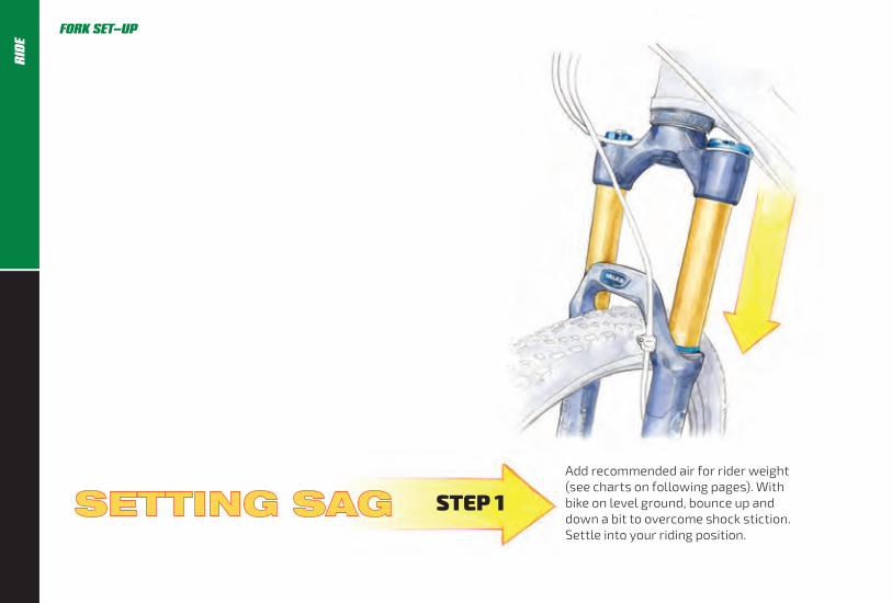
Add recommended air for rider weight (see charts on following pages). With bike on level ground, bounce up and down a bit to overcome shock stiction. Settle into your riding position.
STEP 1
FORK SET-UPR
IDE

43
Slide o-ring until it rests on wiper, then dismount without disturbing o-ring’s position.
Measure sag–the distance from o-ring to wiper. Start with sag of 15–20% of travel and adjust to your preference.
STEP 2 STEP 3
FORK SET-UP RID
E

44
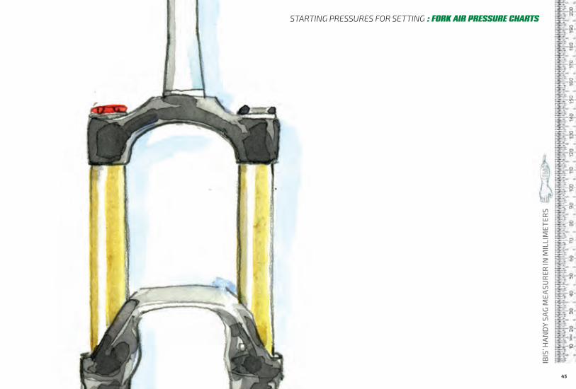
FORK AIR PRESSURE CHARTS : STARTING PRESSURES FOR SETTING SAG
DO NOT EXCEED MAXIMUM AIR PRESSURES
FOX FLOAT 36 : 27.5 / 29*RIDER WEIGHT 160MM
LB KG PSI
120-130 54-59 55
130-140 59-64 59
140-150 64-68 63
150-160 68-73 67
160-170 73-77 75
170-180 77-82 76
180-190 82-86 80
190-200 86-91 85
200-210 91-95 89
210-220 95-100 93
220-230 100-104 97
230-240 104-109 102
240-250 109-113 106
MAX 120
FOX FLOAT 34 : 27.5 / 29*RIDER WEIGHT 140MM
LB KG PSI
120-130 54-59 58
130-140 59-64 63
140-150 64-68 68
150-160 68-73 72
160-170 73-77 77
170-180 77-82 82
180-190 82-86 86
190-200 86-91 91
200-210 91-95 96
210-220 95-100 100
220-230 100-104 105
230-240 104-109 110
240-250 109-113 114
MAX 120
*Air pressures above are for both Factory and Performance forks from Fox.
RID
E
45
IBIS
’ HA
ND
Y SA
G M
EASU
RER
IN M
ILLI
MET
ERS
STARTING PRESSURES FOR SETTING : FORK AIR PRESSURE CHARTS

46
SETTING SAG Recommended beginning pressures can be found on pages 50-51. Set the pressure and follow the instructions on this page for setting the sag.
Less pressure gives a slacker seat angle and overall smoother ride. More pressure gives a firmer suspension feel and steeper seat angle and more over the pedals riding position.
Ripmo / Mojo HD4 Shoot for .55” (~14mm) of sag.
Ripley LS Shoot for .45” ( (~11mm) of sag.
Mojo 3 Shoot for .47” (~12mm) of sag.
CHECK THE SAG With the shock in open mode (or ProPedal turned off for earlier shocks), sit on your bike in a normal riding position. Reach down and slide the o–ring up the shock shaft against the wiper seal. Next, gently step off of the bike taking care not to further compress the suspension.
For the Ripley, the distance from the o–ring to the wiper seal should be about 11mm.
On the Mojo HD4 and Ripmo, sag should
be about 14mm for XC and 17–19mm for gravity rides. Experiment and see what works best for your trails and riding style.
FOX FLOAT DPS The Float DPS has totally new internals over prior Float shocks, and is a huge improvement. There is a wider range of compression adjustment when you change positions using the blue lever. The shock has the new EVOL air sleeve that gives both better small bump compliance AND more support though the mid stroke. It also gives increased bottoming resistance.
There’s a 3 position on-the-fly (lever) adjustment like before. They control low speed compression damping. They’re called Open-Medium-Firm. The Open mode is the tunable one (instead of the middle mode being tunable like last year). That enables you to adjust the mode that you use most often, then have the preset Medium and Firm modes if you want to firm things up for fire road climbing or pavement (we rarely use these settings on our bikes).
ADJUSTING REBOUND The Float DPS has adjustable rebound damping. It’s adjusted by turning the red dial on the inside of the lever. Generally you want it as fast as you can set it
REAR SHOCK SET-UPR
IDE

47
without getting bounced off the saddle after a bump or drop (like riding off a curb in the saddle.) If the rebound setting is too slow the shock will be partially compressed when you hit the next bump resulting in “packing down”. Too fast and the bike will bounce you up in the air after bumps and drops. Adjust to your preference.
Our suspension bikes have the following shock and shock hardware specifications:
Ripley Shock • Upper: 21.8mm wide with an 8mm bore• Lower: Bushing removed, 15mm bore• 7.25” (184mm) eye to eye • 1.75” (44mm) shaft travel
Rimpo Shock • Upper: 25mm wide with an 8mm bore• Lower: 15mm wide with an 8mm bore• 210mm eye to eye • 55mm shaft travel
Mojo HD4 Shock: • Upper: 21.8mm wide with an 8mm bore• Lower: 15mm wide with an 8mm bore• 7.875” (200mm) eye to eye • 2.25” (57mm) shaft travel
Mojo 3 Shock: • Upper: 21.8mm wide with an 8mm bore• Lower: Bushing removed, 15mm bore
• 7.875” (200mm) eye to eye • 2” (51mm) shaft travel
SETTING AIR PRESSURE FOR THE FIRST TIME WITH THE EVOL SLEEVE It is critically important to add or remove air from the EVOL sleeve as detailed below to experience the best possible performance.
IMPORTANT NOTE: When adding air to the air chamber, it is crucial to equalize the positive and negative air chambers by slowly compressing the shock through 25% of its travel 10-20 times after every 50psi addition.
Adding air to the shock without periodically equalizing the air chambers can lead to a condition in which the shock has more pressure in the positive chamber than the negative. In this condition the shock will be very stiff and can top-out. You can equalize the air chambers by slowly compressing the shock until you feel and hear a transfer of air. Hold the shock at this point for a few seconds to allow the air to transfer from the positive to the negative chamber.
When releasing air from the air chamber, it is important to do this
slowly so the shock can transfer air from the negative to positive chamber and then be released through the Schrader valve.
Releasing the air pressure too quickly can induce a condition in which the negative chamber has more pressure than the positive chamber. In this condition the shock will compress into its travel and not fully extend. You can remedy this by adding air pressure until the shock extends, then slowly compressing the shock through 25% of its travel 10-20 times. For a more detailed explanation, go to: http://www.ridefox.com\help.php?m=bike&id=555# usingtheevolairsleeve
REAR SHOCK SET-UP RID
E

48
REAR SHOCK SET-UP
AFTERMARKET SUSPENSION We work closely with the engineers at Fox to custom tune the shocks on each of our bikes. If you are looking to update your Ibis to the latest 2019 Fox suspension, here is all the information you will need, part numbers, descriptions and what you will need to have a Fox trained technician change on your new shock.
Fork aftermarket part numbers for 2019 are included too. We use stock tunes on all the forks so no modification is needed.
AFTERMARKET FORKS
BIKE MODEL FOX AM P/N DESCRIPTION
Mojo 3 910-20-550 2019, 34, K, FLOAT, 27.5in, F-S, 140, FIT4, 3Pos-Adj, Matte Blk, Orange/Matte Blk Logo, 15QRx110, 1.5 T, 44mm Rake
Mojo HD4 910-20-535 2019, 36, K, FLOAT, 27.5in, F-S, 160, Grip 2, HSC/LSC HSR/LSR, Matte Blk, Orange/Matte Blk Logo, 15QRx110, 1.5 T, 44mm Rake
Ripley 910-20-572 2019, 34, K, FLOAT, 29in, F-S, 130, FIT4, 3Pos-Adj, Matte Blk, Orange/Matte Blk Logo, 15QRx110, 1.5 T, 51mm Rake
Ripmo 910-20-624 2019, 36, K, FLOAT, 29in, F-S, 160, Grip 2, HSC, LSC, HSR, LSR, Matte Blk, Orange/Matte Blk Logo, 15QRx110, 1.5 T, 44mm Rake, AM
RID
E

49
AFTERMARKET SHOCKS
BIKE MODEL FOX AM P/N DESCRIPTIONNOTES FOR CONVERTING AFTERMARKET DAMPER TO IBIS OEM SPECIFICATION
Mojo 3 Float DPS 972-01-383 2019, FLOAT DPS, F-S, K, 3pos-Adj, Evol LV, FOX, AM, 7.875, 2.0, 0.6 Spacer, LCM, LRM, CMF, Orange Logo
Revalve damper to DCL, DRM, CMF. Install 0.8 cu in air volume reducer.
Mojo 3 Float DPS (Roxy Tune)
972-01-383 2019, FLOAT DPS, F-S, K, 3pos-Adj, Evol LV, FOX, AM, 7.875, 2.0, 0.6 Spacer, LCM, LRM, CMF, Orange Logo
Revalve damper to DCXL, DRL, CMF. Install 0.8 cu in air volume reducer.
Mojo 3 Float X2 973-01-210 2019, FLOAT X2, F-S, K, 2pos-Adj, FOX, AM, 7.875, 2.0, 0.3 Spacer x2, CM, Orange, Gray Logo
Remove 1 air volume reducer.
Mojo HD4 Float X2 973-01-209 2019, FLOAT X2, F-S, K, 2pos-Adj, FOX, AM, 7.875, 2.25, 0.3 Spacer x2, CM, Orange, Gray Logo
Revalve damper to CL. Remove all air volume reducers.
Mojo HD4 Float DPX2 973-01-222 2019, FLOAT DPX2, F-S, K, 3pos-Adj, Evol LV, FOX, AM, 7.875, 2.25, 0.2 Spacer, CM, DRM, Rezi A F F, Orange Logo
Remove air volume reducer.
Ripley Float DPS 972-01-386 2019, FLOAT DPS, F-S, K, 3pos-Adj, Evol SV, FOX, AM, 7.25, 1.75, LCM, LRM, CMF, Orange Logo
Revalve damper to DCL, DRM, CMF. Install 0.2 cu in air volume reducer.
Ripmo Float X2 N/A N/A 210x55 Float X2 is currently OEM only.
Ripmo Float DPX2 973-01-219 2019, FLOAT DPX2, F-S, K, 3pos-Adj Evol LV, FOX, AM, 210, 55, 0.2 Spacer, CM, DRM, Rezi A F M+, Orange Logo
Revalve damper to CEC001, RLA014, AFM. Install 0.4 cu in air volume reducer.
RID
EREAR SHOCK SET-UP

50
FOX DPS EVOL : RIPLEY LS
25% SAG
RIDER WEIGHT PRESSURE
LB PSI
100 120
120 140
140 160
160 200
180 200
200 230
220 260
250 300
FOX X2 : MOJO HD4
25% SAG
RIDER WEIGHT PRESSURE
LB PSI
125 135
140 160
165 180
190 210
220 240
250 MAX 250PSI!
FOX X2 : RIPMO
25% SAG
RIDER WEIGHT PRESSURE
LB PSI
125 135
140 170
165 190
190 220
220 250 MAX!
FOX DPS EVOL : MOJO 3
25% SAG
RIDER WEIGHT PRESSURE
LB PSI
100 120
120 140
140 160
160 200
180 200
200 230
220 260
250 300
FOX DPX2 : MOJO HD4
25% SAG
RIDER WEIGHT PRESSURE
LB PSI
125 165
140 200
165 220
190 250
220 280
250 310
FOX DPX2 : RIPMO
25% SAG
RIDER WEIGHT PRESSURE
LB PSI
125 145
140 190
165 215
190 255
220 300
240 350 MAX!
REAR SHOCK AIR PRESSURE CHARTS : STARTING PRESSURES FOR SETTING SAG
IMPORTANT NOTE ABOUT FOX DPS EVOL SHOCKS: We valve the shocks so that they give a very plush feeling at 25% and more sag is not needed to increase traction.
To set the sag, the general rule of thumb is:• For rider weight under 180lbs.
Shock pressure = rider weight + 20.• For rider weight 180-240lbs.
Shock pressure = rider weight + 30.• For rider weight above 240lbs.
Shock pressure = rider weight + 50.• For riders under 120lbs on the Mojo 3,
we offer the Roxy Tune shock (but it is not required!).
RID
E

51
STARTING BASE SETTINGS : REAR SHOCK AIR PRESSURE CHARTS
FOX FLOAT X2 BASE SETTINGS *COUNT CLICKS FROM CLOSED: 0 CLICKS = CLOSED*
AIR SPRINGPRESSURE
RECOMMENDEDLSR SETTING
RECOMMENDEDHSR SETTING
RECOMMENDEDLSC SETTING
RECOMMENDEDHSC SETTING
130 21 14 22 23
140 20 13 22 23
150 19 13 21 23
160 18 12 21 23
170 17 12 20 23
180 16 11 19 23
190 15 11 19 23
200 14 10 18 22
210 13 10 17 21
220 12 9 17 20
230 11 9 16 19
240 10 8 15 18
250 9 8 15 17
FOX DP X2 REBOUND SETTINGS
AIR SPRINGPRESSURE
STARTING REBOUND SETTING
<120 Open (counter-clockwise)
120-140 13
140-160 12
160-180 11
180-200 10
200-220 8
220-240 7
240-260 5
260-280 3
280-300 2
Rebound Compression
All settings above are +/-1
RID
E

52
WORKING ON THE RIPLEY This information is shown in a video:
http://tinyurl.com/n8f9o4p
Should you find it necessary to replace any of the bearings on the Ripley eccentric linkages, you will need to remove the swingarm. For that, you will need the following tools:
• 12mm open end wrench • 2 x 6mm Allen wrench • 1 x 5mm Allen wrench • 2 x 4mm Allen wrenches
BEARING REPLACEMENT Please refer to the section on Ripley Swingarm Removal on pages 62-65. Complete instructions can be found on this video:
http://tinyurl.com/n8f9o4p or on our website at http://www.ibiscycles.com/support/technical_articles/ ripley_bearing_replacement/
RIPLEY BEARING SPECS Eccentric Core Inner Bearings: • 6806-2RS (30 x 42 x 7)
These are the same as BB30 bearings.
Lower Outer Bearings: • 608-RS 8x22x7
These mount in the swingarm and can be found in skate shops.
Upper Outerbearing: • 698-RS 8x19x6
These mount in the swingarm and can be found in skate shops.
BEARING MAINTENANCE AND REPLACEMENTM
AIN
TAIN
53
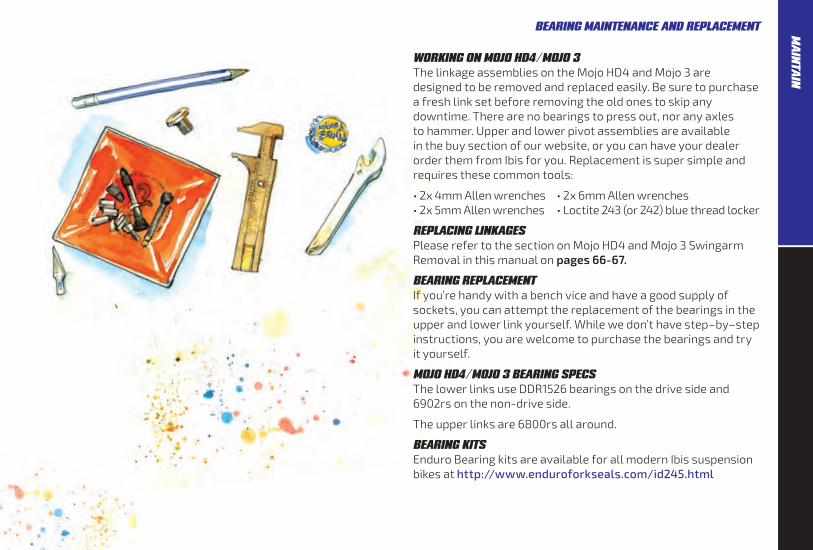
WORKING ON MOJO HD4 / MOJO 3 The linkage assemblies on the Mojo HD4 and Mojo 3 are designed to be removed and replaced easily. Be sure to purchase a fresh link set before removing the old ones to skip any downtime. There are no bearings to press out, nor any axles to hammer. Upper and lower pivot assemblies are available in the buy section of our website, or you can have your dealer order them from Ibis for you. Replacement is super simple and requires these common tools:
• 2x 4mm Allen wrenches • 2x 6mm Allen wrenches • 2x 5mm Allen wrenches • Loctite 243 (or 242) blue thread locker
REPLACING LINKAGES Please refer to the section on Mojo HD4 and Mojo 3 Swingarm Removal in this manual on pages 66-67.
BEARING REPLACEMENT If you’re handy with a bench vice and have a good supply of sockets, you can attempt the replacement of the bearings in the upper and lower link yourself. While we don’t have step–by–step instructions, you are welcome to purchase the bearings and try it yourself.
MOJO HD4 / MOJO 3 BEARING SPECS The lower links use DDR1526 bearings on the drive side and 6902rs on the non-drive side.
The upper links are 6800rs all around.
BEARING KITS Enduro Bearing kits are available for all modern Ibis suspension bikes at http://www.enduroforkseals.com/id245.html
BEARING MAINTENANCE AND REPLACEMENT MA
INTAIN

iscg adapter
shock mount bolt
m4x12 bolt
m2.2x6 phillips screw
headbadge and bolts
seat binder
upper link bolt
lower link
lower pivot bolt1/16x7/8 o-ring
1x18 o-ring
bushing washer
igus bushing
igus bushing
clevis sa bolt
upper link
m6x16 bolt
shock mount bolt
clevis nut
seat binder bolt
derailleur hanger
derailleur hanger bolt
clevis reducer
seatstay guard
chainstay guard chainstay plate
rock gaurd
m4 rivnut
m5 rivnut
54
RIPMO : FRAME HARDWAREM
AIN
TAIN

eccentric cap nut
lower eccentric shaft bolt
lower shock nut
clevis
clevis reducer
clevis bushing
lower shock bolt
single stop
derailleur hanger
single stop
derailleur hanger boltchainsuck plate
lower swingarm bearing
eccentric cap bolt
double port/stop
upper pivot shaft nut
lower eccentric core
upper swingarm bearing
lower eccentric spacer
upper eccentric shaft bolt
upper eccentric core
outer eccentric bearings
outer eccentric bearings
upper and lower eccentric caps
upper eccentric spacer
forward shock mount bolt
double port/stop
m4x8 flat head bolt
single ports
clevis pivot nut
clevis pivot bolts
seatstay guard
clevis bushing o-ring
chainstay guard
55
RIPLEY LS : FRAME HARDWARE MA
INTAIN

optional iscg-05 mount
derailleur hanger
derailleur hanger bolt
single stop
chain suck stainless steel plate
chain stay rubber guard
lower pivot shaft nuts
lower link
clevis bolt
clevis
shock mount bolt
rock guard
clevis reducers
clevis bushing
lower link pivot shafts
single port
single stop
single port
upper link
upper link bolts
forward shock mount bolt
56
FRAME HARDWARE : MOJO HD4M
AIN
TAIN

single port
double port/stop
single port
double stop
upper link
cable guard
forward shock mount bolt
lower link shaft bolts
lower link shaft
chain suck stainless steel plate
upper link bolt
lower link
chain stay rubber guard
derailleur hanger
derailleur hanger bolt
bushing reducer
boost front derailleur mount
clevis
clevis nut
igus bushing
clevis shock bolt
clevis shock nut
clevis mounting bolt
single stop
optional iscg-05 mount
57
MOJO 3 : FRAME HARDWARE MA
INTAIN

58
TORQUE SPECS
MOJO 3 Note on 243 Loctite: Shake the bottle well before applying!
HARDWARE TORQUE SPEC. THREAD TREATMENT
Cable Port 2 Nm Grease
Clevis to Swingarm Bolts 8 Nm Titanium Bolts: Loctite 243 on thread, Ti anti-seize under head of bolt
Lower Links 24 Nm Loctite 243
Lower Shock to Clevis Bolts 20 Nm Titanium Bolts: Loctite 243 on thread, Ti anti-seize under head of bolt
Rear Brake Caliper 6 Nm Loctite 243
Upper Link Bolts 10 Nm Loctite 243
Upper Shock Mount Bolts 10 Nm Loctite 243 on thread, grease under head of bolt or mylar washer
Seat Binder 5 Nm Ti anti-seize
Derailleur Hanger Bolt 5 Nm Grease
MOJO HD4
HARDWARE TORQUE SPEC. THREAD TREATMENT
Cable Port 2 Nm Grease
Clevis to Swingarm Bolts 15 Nm Titanium Bolts: Loctite 243 on thread, Ti anti-seize under head of bolt
Lower Links 24 Nm Loctite 243
Lower Shock to Clevis Bolts 20 Nm Titanium Bolts: Loctite 243 on thread, Ti anti-seize under head of bolt
Rear Brake Caliper 6 Nm Loctite 243
Upper Link Bolts 10 Nm Loctite 243
Upper Shock Mount Bolts 10 Nm Loctite 243 on thread, grease under head of bolt or mylar washer
Seat Binder 5 Nm Ti anti-seize
Derailleur Hanger Bolt 5 Nm Grease
NOTE: If you have a Mojo 3 or newer HD4 with the black anodized upper shock mount bolt, be sure to use copious amounts of grease under the bolt head if you don’t have the mylar washer under the bolt head. Or we’d be happy to send you a washer if you don’t have one.
BUSHINGS On all models, apply Slick Honey (grease) to all bushings during reassembly.
HEXLE REAR AXLE
There is not a numerical torque figure for the Hexle. We recommend tightening the 5mm with your multi tool that you carry with you. This way you’ll be able to remove it in case of a flat out on a ride.
MA
INTA
IN

59
MOJO HD4 : FRAME HARDWARE
RIPMO
HARDWARE TORQUE SPEC. THREAD TREATMENT
Lower Link 6mm Preload Bolts 2 Nm Loctite 243 on thread, grease on flange
Lower Link 5mm pinch bolts 10 Nm Loctite 243
Swingarm to Clevis pivot bolts 5 Nm Loctite 243
Lower shock clevis bolt 20 Nm Ti anti-seize
Upper link bolts 10 Nm Loctite 243
Forward shock mount bolt 10 Nm Loctite 243
Seat Binder 5 Nm Ti anti-seize
Derailleur Hanger Bolt 5 Nm Grease
HAKKA MX
HARDWARE TORQUE SPEC. THREAD TREATMENT
Seat Binder 5 Nm Ti anti-seize
Derailleur Hanger Bolt 5 Nm Grease
RIPLEY LS Note on 243 Loctite: Shake the bottle well before applying!
HARDWARE TORQUE SPEC. THREAD TREATMENT
Clevis to Swingarm Bolts 8 Nm Grease
Lower Shock to Clevis Bolts 24 Nm Loctite 243
Eccentric Shaft Bolts 8 Nm Titanium Bolts: Loctite 243 on thread, Ti anti-seize under head of bolt
Upper and Lower Eccentric Core Bolts 8 Nm Loctite 243
Upper Shock Mount Bolts 10 Nm Loctite 243
Seat Binder 5 Nm Ti anti-seize
Derailleur Hanger Bolt 5 Nm Grease
MA
INTAIN
60
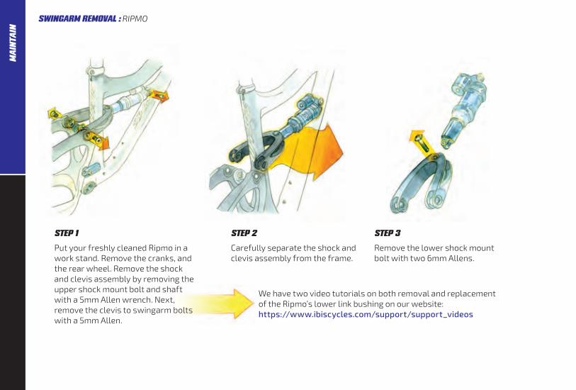
STEP 1
Put your freshly cleaned Ripmo in a work stand. Remove the cranks, and the rear wheel. Remove the shock and clevis assembly by removing the upper shock mount bolt and shaft with a 5mm Allen wrench. Next, remove the clevis to swingarm bolts with a 5mm Allen.
STEP 3
Remove the lower shock mount bolt with two 6mm Allens.
We have two video tutorials on both removal and replacement of the Ripmo’s lower link bushing on our website: https://www.ibiscycles.com/support/support_videos
STEP 2
Carefully separate the shock and clevis assembly from the frame.
SWINGARM REMOVAL : RIPMOM
AIN
TAIN

61
STEP 4
Remove 4 upper link bolts.
STEP 5
Remove upper link from swingarm and front triangle.
STEP 6
Loosen pinch bolts, remove preload bolts. Link is two pieces, to remove pull two sides of link apart while supporting the swingarm.
* To reassemble your bike, follow the steps in reverse order. Remember to use a little Loctite blue thread locker (we prefer Loctite 243) on all steel and aluminum fasteners, and to use anti–seize on all titanium fasteners. Ripmo shock and clevis reassembly: Use Ti anti-seize on the shock mount bolt. On the upper shock mount, be careful not to lose the thin black washers that go on the outside of the shock eyelet. Refer to the torque chart on page 59.
RIPMO : SWINGARM REMOVAL MA
INTAIN
62
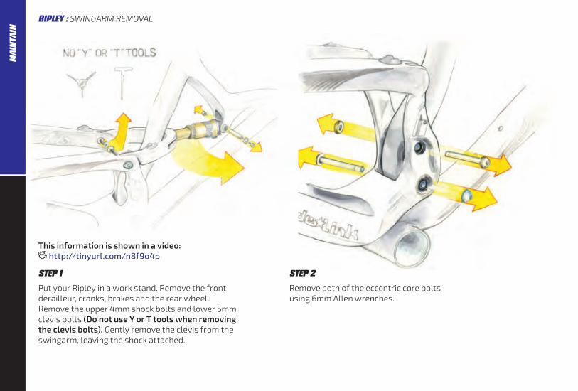
This information is shown in a video: http://tinyurl.com/n8f9o4p
STEP 1
Put your Ripley in a work stand. Remove the front derailleur, cranks, brakes and the rear wheel. Remove the upper 4mm shock bolts and lower 5mm clevis bolts (Do not use Y or T tools when removing the clevis bolts). Gently remove the clevis from the swingarm, leaving the shock attached.
STEP 2
Remove both of the eccentric core bolts using 6mm Allen wrenches.
RIPLEY : SWINGARM REMOVALM
AIN
TAIN

63
STEP 3
Remove the countersunk bolt from each eccentric core cap. You might need to use a 12mm open end wrench to prevent the eccentric from rotating. Do not use a crescent wrench, cave man!
STEP 4
Gently remove the cap, and then you will be able to push the eccentric core out of the frame.
SWINGARM REMOVAL : RIPLEY MA
INTAIN

64
NOTE Special tools are needed to remove and replace the Ripley bearings in the seattube and in the swingarm. Please do not attempt to remove and replace these bearings without the tool.
Instructions on removal and re-installation of the bearings using the Ibis Clemens Tool (drawing to the right) can be found in the video above and on the Ibis website under Support>Technical Articles>Ripley Bearing Replacement. You can purchase the tool at our online store: http://store.ibiscycles.com and search Clemens bearing tool.
To reinstall the swingarm, work in the reverse order. If you are replacing the eccentric bearings, be sure to clean the bearing surfaces in the frame and the bearings themselves, making sure the press surfaces are free of any contamination such as grease or oil. Apply a thin layer of Loctite 680 retaining compound and use the Clemens tool to
This information is shown in a video: http://tinyurl.com/mfttd8o
press in the bearings. Let the bearing retainer dry overnight before riding the bike again. Add grease to the core when reinstalling, and a lightly grease the inner lip of the eccentric cap. Don’t forget the two spacers that go between the BB30 bearings in the seattube. The chamfered hole on the cap aligns with the threaded hole on the eccentric core. Use blue Loctite on the bolt.
Use a 12mm open end wrench to align the eccentrics so that the flats are horizontal and at the 9 o’clock position when the frame is parallel with the ground. Gently slide the swingarm onto the eccentrics. Insert the swingarm bolts, lower bolt from the non drive side, upper from the drive side.
The conehead nut goes on the lower bolt, on the drive side. Ride it and weep (with joy).
SWINGARM REMOVAL : RIPLEYM
AIN
TAIN
65
RIPLEY : SWINGARM REMOVAL
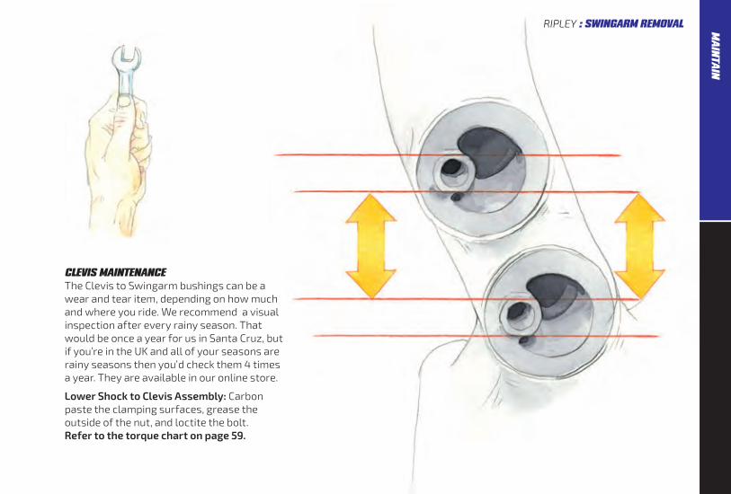
CLEVIS MAINTENANCE The Clevis to Swingarm bushings can be a wear and tear item, depending on how much and where you ride. We recommend a visual inspection after every rainy season. That would be once a year for us in Santa Cruz, but if you’re in the UK and all of your seasons are rainy seasons then you’d check them 4 times a year. They are available in our online store.
Lower Shock to Clevis Assembly: Carbon paste the clamping surfaces, grease the outside of the nut, and loctite the bolt. Refer to the torque chart on page 59.
MA
INTAIN

66
STEP 1
Put your freshly cleaned Mojo in a work stand. Remove the front derailleur, cranks, and the rear wheel. Remove the shock and clevis assembly by removing the upper shock mount bolt and shaft with two 4mm Allen wrenches. Next, remove the clevis to swingarm bolts with a 5mm Allen.
STEP 3
Remove the lower shock mount bolt with two 6mm Allens.
Mojo 3 lower shock mount to clevis bolt assembly: Loctite 243 on the thread, carbon paste on the clevis where it contacts the shock eyelet, grease on the shaft of the nut.
Mojo HD4 shock and clevis reassembly: Use Ti anti-seize on the shock mount bolt. On the upper shock mount, be careful not to lose the thin black washers that go on the outside of the shock eyelet.
STEP 2
Carefully separate the shock and clevis assembly from the frame.
SWINGARM REMOVAL : MOJO HD4 / MOJO 3M
AIN
TAIN

67
STEP 4
Remove front lower link shaft and the two forward upper link bolts.
STEP 5
Pull the swingarm with the linkages still attached away from the front triangle.
STEP 6
Remove the axle in the lower link that passes through the swingarm and separate the link from the swingarm. Also remove the upper link from the swingarm.
MOJO HD4 / MOJO 3 : SWINGARM REMOVAL
* To reassemble your bike, follow the steps in reverse order. Remember to use a little Loctite blue thread locker (we prefer Loctite 243) on all steel and aluminum fasteners, and to use anti–seize on all titanium fasteners. Refer to the torque chart on page 58.
MA
INTAIN

68
Ibis Cycles warrants Ibis frames to be free from defects in materials and workmanship for a period of 7 years from date of sale. This limited warranty applies to the original owner and is nontransferable. Ibis will, at its sole discretion, repair or replace any frame or frame component that it determines to be defective. This warranty does not cover normal wear and tear, nor does it apply to damage that is the result of abuse, neglect, improper assembly, improper maintenance, alteration, misuse or massive hucking. The costs of disassembly, reassembly or repair of any attached components are not covered by this warranty and are the responsibility of the original owner. Under no circumstance are the costs of shipping to or from Ibis covered by this limited warranty.
This warranty applies exclusively to Ibis bicycles manufactured after January 1, 2016.
NO FAULT REPLACEMENT Should your Ibis be involved in a crash or other non–warranty situation, Ibis Cycles will make replacement parts available at a minimum charge to the original owner. Ibis Cycles does this
at its sole discretion and reserves the right to refuse this offer, so don‘t go crashing your bike. Unless otherwise provided, the sole remedy under the above warranty, or any implied warranty, is limited to the replacement of defective parts with those of equal or greater value at the sole discretion of Ibis Cycles.
In no event shall Ibis Cycles be held responsible for direct, incidental or consequential damages, including, without limitation, damages for personal injury, property damage, or economic losses, whether based on contract, warranty, negligence, product liability, or any other theory.
WARRANTY REGISTRATION Don’t forget to register your warranty online at: http://www.ibiscycles.com/support/warranty/warranty_registration/
The Fox forks and shocks we use on our bikes are warrantied for one year. For USA Warranty Service: (800) FOX-SHOX / 369-7469 [email protected]
For International Warranty Service: Contact a Fox service center:
http://www.ridefox.com/fox17/contact.php? r=worldwide&ref=service
PARTS Find these online at the buy portion our website or get them directly from your Ibis dealer. Contact us or your dealer for more info. We recommend you always ride with one or two spare derailleur hangers.
SERIAL NUMBER We recommend you write down your serial number for future reference. The serial number is located under the bottom bracket.
Note that if you have a Mojo HD4 with a cable guard installed, you will need to remove the cable guard to obtain the serial number. We want you to register the serial numbers on the front triangle, not the swingarm.
WARRANTYW
AR
RA
NTY
/ REG
ISTR
ATIO
N

69
Specifications and construction details given are not binding. We reserve the right to carry out modifications without prior notice. RIDE MORE, WORK LESS.
DOCUMENTATION
BIKE INFO
MODEL :
PAINT COLOR :
FRONT TRIANGLE SERIAL NO.
SWINGARM SERIAL NO.
NEAREST IBIS DEALER
NAME :
ADDRESS :
SERVICE MANAGER :
PHONE :
RIDER INFO
NAME :
ADDRESS:
PHONE :
EMAIL :
FORK SETTINGS
PSI :
CLICKS REBOUND:
CLICKS COMPRESSION:
TUNING NOTES:
SHOCK SETTINGS
PSI :
CLICKS REBOUND:
CLICKS COMPRESSION:
TUNING NOTES:
FIRST RIDE ON THE NEW RIG
ROUTE :
CREW:
VERDICT:
WA
RR
ANTY / R
EGISTR
ATION

70
IMPRESS YOUR RIDING BUDDIES WITH CHUCK’S HOMEMADE ENERGY BARS
INGREDIENTS • 1/2 cup salted almonds
• 1/2 cup roasted sunflower seeds, or other chopped nuts
• 2 cups raisins, or other chopped dried fruit
• 2 cups rolled or instant oats
• 2 cups toasted rice cereal, such as Rice Krispies
• 1/4 cup toasted wheat germ, (optional)
• 1/2 cup creamy or crunchy natural almond butter
• 1/2 cup packed brown sugar
• 1/2 cup honey (or agave sweetener)
• 1 teaspoon vanilla extract
PREPARATION 1. Coat a 9–by–13–inch baking pan
with cooking spray.
2. Combine the almonds, sunflower seeds (or other nuts), raisins (or other dried fruit), oats, rice cereal and wheat germ (if using) in a large bowl.
3. Combine almond butter, brown sugar and corn syrup (or honey) in a large microwaveable bowl; microwave on High until bubbling, 1 to 2 minutes. Add vanilla and stir until blended. Pour the almond butter mixture over the dry ingredients and stir until coated.
4. Transfer the mixture to the prepared pan. Press down firmly. (It helps to coat your fingers with cooking spray.) Let stand for about 1 hour to harden. Cut into bars.
TIPS AND NOTES Make Ahead Tip: Individually wrap and keep at room temperature for up to 1 week or freeze for up to 1 month. Thaw at room temperature. Makes 16 Bars, better than Method Man in his prime.
NUTRITION Per serving: 255 calories; 9g fat (1g sat., 2g mono); 0 mg cholesterol; 42g carbohydrates; 5g protein; 3g fiber; 95mg sodium; 242mg potassium.
CHUCK’S RECIPEEX
TRA
S

71
TOLL FREE (formerly called an 800 number but all 800’s are used up we guess)1–866–424–7635 (1–866–IBIS–635)
NOT TOLL FREE (unless maybe you’re at work)1–831–461–1435 (Or if you’re all fancy and internationally savvy: +1–831–461–1435)
ELECTRONIC MAIL (sometimes referred to as “email”)[email protected]
FAX (remember those?) 1-831-461-1475
REALLY OLD FASHIONED SNAIL MAIL2240 Delaware Ave. Santa Cruz, CA 95060.
IBISCYCLES.COM
EXTRA
SCONTACT INFORMATION

72
ALPHABETICAL INDEX
Airstream 2–3Bearing Specs, Mojo 53Bottle Cage 36Cable Routing 10-29Cannoli 23Chuck’s Recipe 70Fork Set-up 39-45Fox Grip2 Settings 41Frame Care 36-37Frame Hardware Drawings 54-57Torque Specs 58-59Geometry 4-6Hand Job 75
Introduction 2ISCG 05 30Method Man 70Peanut Butter Wrench 71Rear Shock Air Pressure Chart 50-51Rear Shock Tuning 46-51Rebounding from a bad relationship 38Ride and weep with joy 64Serial Number 68Snail Mail 71Stack and Reach 4-6Swingarm Removal 60-67Warranty 68
ALPHABETICAL INDEXEX
TRA
S

73
52 Ripley: Replacing the Eccentric Link Bearings
http://tinyurl.com/n8f9o4p
62 Ripley: Swingarm Removal
http://tinyurl.com/n8f9o4p
64 Ripley: Bearing Tool
http://tinyurl.com/mfttd8o
EXTRA
SVIDEO INDEX

74
EXTR
AS
NOTES

75


