Thank you for purchasing our product, an ideal radio system for beginners or experienced users alike.
Read this manual carefully before operation in order to ensure your safety, and the safety of others or the safe operation of your system.
If you encounter any problem during use, refer to this manual first. If the problem persists, contact your local dealer or visit our service and support website for help:
www.flysky-cn.com/service.asp
2
FS-l6SDigital proportional radio control system
Table of contents1. Safety ................................................................................................................................................4
2.4 USB Simulator Mode ...................................................................................................................................... 93. Getting Started ..............................................................................................................................10
3.1 Transmitter Battery Installation .................................................................................................................103.2 Connecting the Receiver and Servos .....................................................................................................10
4. Operation Instructions .................................................................................................................114.1 Power On ..........................................................................................................................................................114.2 Binding...............................................................................................................................................................114.3 Pre-use Check .................................................................................................................................................114.4 Power Off .........................................................................................................................................................12
5. Home Screen ..................................................................................................................................135.1 Fly Mode ...........................................................................................................................................................14
6. Function Settings............................................................................................................................156.1 Reverse Function ............................................................................................................................................156.2 End Points Function ......................................................................................................................................156.3 Subtrim Function ..........................................................................................................................................156.4 Aux Channels ...................................................................................................................................................166.5 Mix.......................................................................................................................................................................166.6 Bright ./Sound .................................................................................................................................................176.7 Output Mode ...................................................................................................................................................186.8 Sticks Mode ......................................................................................................................................................186.9 Factory Reset ...................................................................................................................................................186.10 Firmware Update .........................................................................................................................................186.11 Receiver Update ...........................................................................................................................................186.12 About FS-i6S..................................................................................................................................................196.13 Timers ..............................................................................................................................................................19
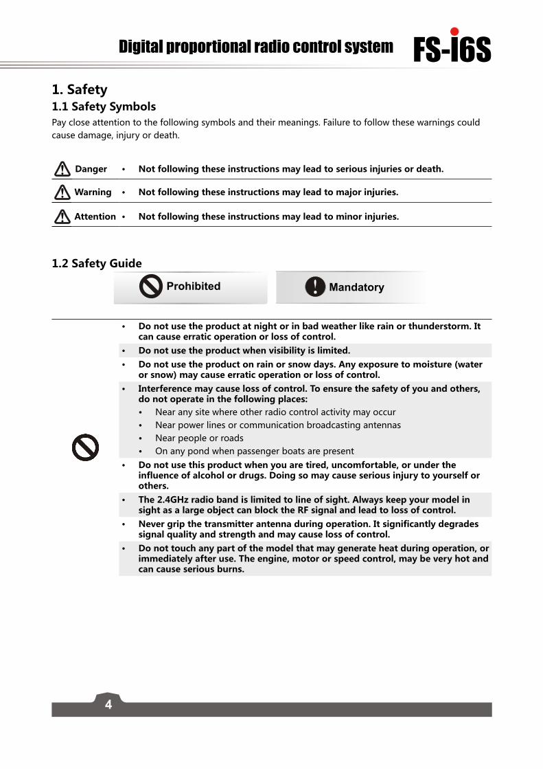
1. Safety 1.1 Safety Symbols Pay close attention to the following symbols and their meanings. Failure to follow these warnings could cause damage, injury or death.
Danger • Not following these instructions may lead to serious injuries or death.
Warning • Not following these instructions may lead to major injuries.
Attention • Not following these instructions may lead to minor injuries.
1.2 Safety Guide
Prohibited Mandatory
• Do not use the product at night or in bad weather like rain or thunderstorm. It can cause erratic operation or loss of control.
• Do not use the product when visibility is limited. • Do not use the product on rain or snow days. Any exposure to moisture (water
or snow) may cause erratic operation or loss of control.• Interference may cause loss of control. To ensure the safety of you and others,
do not operate in the following places:• Near any site where other radio control activity may occur• Near power lines or communication broadcasting antennas• Near people or roads• On any pond when passenger boats are present
• Do not use this product when you are tired, uncomfortable, or under the influence of alcohol or drugs. Doing so may cause serious injury to yourself or others.
• The 2.4GHz radio band is limited to line of sight. Always keep your model in sight as a large object can block the RF signal and lead to loss of control.
• Never grip the transmitter antenna during operation. It significantly degrades signal quality and strength and may cause loss of control.
• Do not touch any part of the model that may generate heat during operation, or immediately after use. The engine, motor or speed control, may be very hot and can cause serious burns.
5
• Misuse of this product may lead to serious injury or death. To ensure the safety of you and your equipment, read this manual and follow the instructions.
• Make sure the product is properly installed in your model. Failure to do so may result in serious injury.
• Make sure to disconnect the receiver battery before turning off the transmitter. Failure to do so may lead to unintended operation and cause an accident.
• Ensure that all motors operate in the correct direction. If not, adjust the direction first.
• Make sure the model flies within a certain distance. Otherwise, it would cause loss of control.
6
FS-l6SDigital proportional radio control system
2. Introduction The FS-i6S transmitter and FS-iA6B receiver constitute a 10 channel 2.4GHz AFHDS 2A digital proportional computerized R/C system. This system supports quadcopters.
2.1 System FeaturesThe AFHDS 2A (Automatic Frequency Hopping Digital System Second Generation) developed and patented by FLYSKY is specially developed for all radio control models. Offering superior protection against interference while maintaining lower power consumption and high reliable receiver sensitivity, FLYSKY's AFHDS technology is considered to be one of the leaders in the RC market today.
Bidirectional CommunicationCapable of sending and receiving data, each transmitter is capable of receiving data from temperature, altitude and many other types of sensors, servo calibration and i-BUS Support.Multi-channel Hopping FrequencyThis systems bandwidth ranges from 2.4055GHz to 2.475GHz. This band is divided in 140 channels. Each transmitter hops between 16 channels (32 for Japanese and Korean versions) in order to reduce interference from other transmitters. Omni-directional Gain AntennaThe high efficiency Omni-directional high gain antenna cuts down on interference, while using less power and maintaining a strong reliable connection.Unique ID Recognition SystemEach transmitter and receiver has it's own unique ID. Once the transmitter and receiver have been paired, they will only communicate with each other, preventing other systems accidentally connecting to or interfering with the systems operation.Low Power ConsumptionThe system is built using highly sensitive low power consumption components, maintaining high receiver sensitivity, while consuming as little as one tenth the power of a standard FM system, dramatically extending battery life.
7
2.2 Transmitter Overview
Left Gimbal Right Gimbal
Power ButtonPower Button
SwD SwA
SwC SwB
Neck Strap Eye
Handle
Key 1Key 2
Battery Cover
USB Port PS/2 Port
VrA VrB
Phone Holder Mounting Point
Capacitive Touch Screen
8
FS-l6SDigital proportional radio control system
2.2.1 Transmitter Antenna Precautions:
• For best signal quality, make sure that the antenna is at about a 90 degree angle to the model. Do not point the antenna directly at the receiver.
• Never grip the transmitter antenna during operation. It significantly degrades the RF signal quality and strength and may cause loss of control.
2.2.2 Status IndicatorThe status indicator is used to indicate the power and working status of the transmitter.
• Off: the transmitter is powered off. • Blue light: the transmitter is on and working.• Flashing: low battery or low signal alarm.
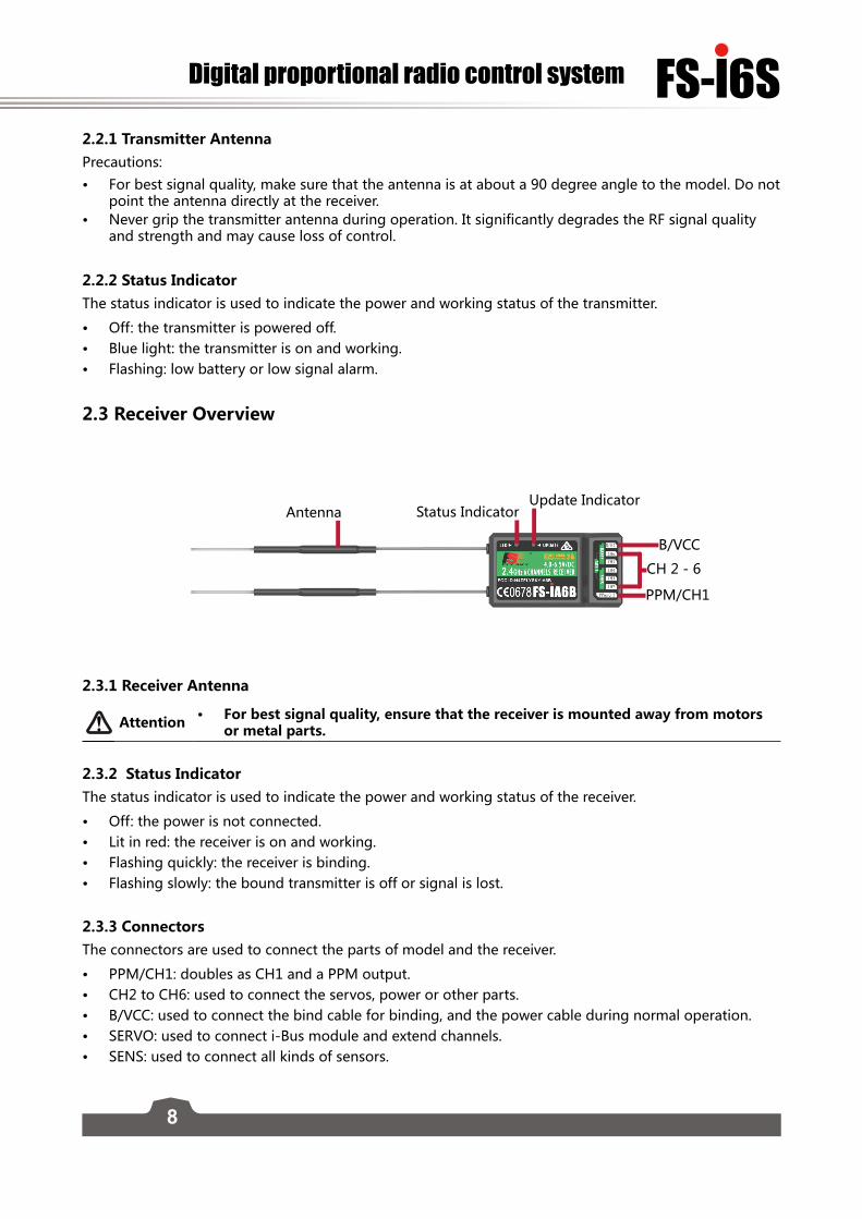
2.3 Receiver Overview
Antenna Status IndicatorUpdate Indicator
CH 2 - 6
B/VCC
PPM/CH1
2.3.1 Receiver Antenna
Attention • For best signal quality, ensure that the receiver is mounted away from motors or metal parts.
2.3.2 Status Indicator The status indicator is used to indicate the power and working status of the receiver.
• Off: the power is not connected. • Lit in red: the receiver is on and working.• Flashing quickly: the receiver is binding.• Flashing slowly: the bound transmitter is off or signal is lost.
2.3.3 Connectors The connectors are used to connect the parts of model and the receiver.
• PPM/CH1: doubles as CH1 and a PPM output. • CH2 to CH6: used to connect the servos, power or other parts.• B/VCC: used to connect the bind cable for binding, and the power cable during normal operation. • SERVO: used to connect i-Bus module and extend channels.• SENS: used to connect all kinds of sensors.
9
2.4 USB Simulator ModeThe system may be used as a HID controller when connected to a computer via USB. When connected to a computer the function is activated automatically and will be recognized by windows as a game controller.
To calibrate or test the system in windows:
• 1. Type "RUN" into the search bar and select the program.• 2. Type "joy.exe" into the "Open:" box and press enter. • 3. Select the system and open properties within the game controller menu.
• Note: any changes made to trims within the system will take effect in the USB mode. If the system is not responding as expected, reset to factory settings in the system menu.
2.5 PS/2 PortThe PS/2 Port can be used to interface with UART devices such as GPS, WIFI or Bluetooth.
10
FS-l6SDigital proportional radio control system
3. Getting Started Before operation, install the battery and connect the system as instructed below.
3.1 Transmitter Battery Installation
Danger • Only use specified battery.
Danger • Do not open, disassemble, or attempt to repair the battery.
Danger • Do not crush/puncture the battery, or short the external contacts.
Danger • Do not expose to excessive heat or liquids.
Danger • Do not drop the battery or expose to strong shocks or vibrations.
Danger • Always store the battery in a cool, dry place.
Danger • Do not use the battery if damaged.
Follow the steps to install the transmitter battery:
1. Open the battery compartment.2. Insert 4 fully-charged AA batteries into the compartment. Make sure that the batteries are inserted in
the correct polarity and make good contact with the battery compartment's contacts. 3. Replace the battery compartment cover.
3.2 Connecting the Receiver and Servos Connect the receiver and the servos as indicated below:
11
4. Operation Instructions After setting up, follow the instructions below to operate the system.
4.1 Power OnFollow the steps below to turn on the system:
1. Check the system and make sure that:• The batteries are fully charged and installed properly. • The receiver is off and correctly installed.
2. Hold the power buttons until screen lights up. 3. Connect the receiver power supply to the B/VCC port on the receiver.
The system is now powerd on. Operate with caution, or serious injury could result.
4.2 BindingThe transmitter and receiver have been pre-bound before delivery. If you are using another transmitter or receiver, follow the steps below to bind the transmitter and receiver:
1. Turn the transmitter on, press , and scroll down and then select [RX bind].
2. Connect the bind cable to the B/VCC port of the receiver.3. Connect the power to any other port. The indicator will start to flash, indicating that the receiver is in
bind mode.
4. Remove the bind and power cable from the receiver. Then connect the power cable to the B/VCC port. 5. Check the servos' operation. If anything does not work as expected, restart this procedure from the
beginning.
4.3 Pre-use CheckBefore operation, perform the following steps to check the system:
1. Check to make sure that all servos and motors are working as expected.2. Check operating distance: one operator holds the transmitter, and another one moves the model
away from the transmitter. Check the model and mark the distance from where the model starts to lose control.
Danger • Stop operation if any abnormal activity is observed.
Danger • Make sure the model does not go out of range.
Attention • Sources of interference may affect signal quality.
12
FS-l6SDigital proportional radio control system
4.4 Power Off Follow the steps below to turn off the system:
1. Disconnect the receiver power.2. Hold the transmitter's power buttons to turn off the transmitter.
Danger • Make sure to disconnect the receiver power before turning off the transmitter. Failure to do so may lead to damage or serious injury.
13
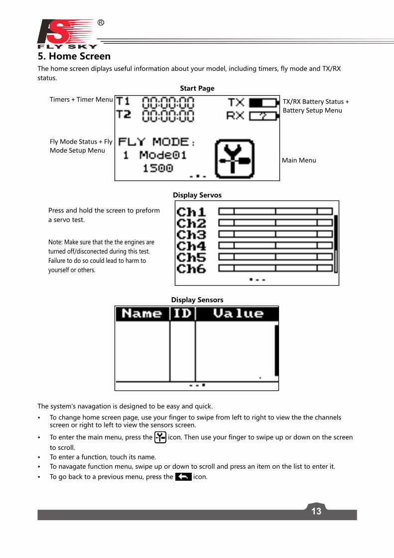
5. Home Screen The home screen diplays useful information about your model, including timers, fly mode and TX/RX status.
Start Page
Main Menu
Timers + Timer Menu TX/RX Battery Status + Battery Setup Menu
Fly Mode Status + Fly Mode Setup Menu
Display Servos
Display Sensors
The system's navagation is designed to be easy and quick.
• To change home screen page, use your finger to swipe from left to right to view the the channels screen or right to left to view the sensors screen.
• To enter the main menu, press the icon. Then use your finger to swipe up or down on the screen
to scroll. • To enter a function, touch its name. • To navagate function menu, swipe up or down to scroll and press an item on the list to enter it.
• To go back to a previous menu, press the icon.
Press and hold the screen to preform a servo test.
Note: Make sure that the the engines are turned off/disconected during this test. Failure to do so could lead to harm to yourself or others.
14
FS-l6SDigital proportional radio control system
5.1 Fly Mode This mode can store settings that can be recalled by toggling a switch.
There are several options available:
• A: Stores the channel used by the flight controller.• 1. Touch the box to the right of the desired channel. • 2. Select the correct decimal and use the up and down arrow keys.• 3. Press the or to confirm or cancel changes.
• B: Stores the first selected activation switch.• C: Stores the second selected activation switch.• D: This number represents the currently selected mode. The name beside the mode number can be
changed. • 1. Touch the box. • 2. Use the onscreen keyboard to enter a new name.
• 3. Select the icon to save and return to the previous menu.
• E: Changes the sensitivity or range of throttle available for each motor. • 1. Touch the box to the right of the desired channel. • 2. Select the correct decimal and use the up and down arrow keys.• 3. Press the or to confirm or cancel changes.
A
B
D
C
E
Assigning modes to switches.
Which modes are available are determined by which switches are assigned. If assigned to a single 2 position switch you will have access to modes 1 and 2 but if assigned to two 2 position switches you will have access to 4 modes. To have access to all 9 modes use the two 3 position switches together.
To cycles through all 9 modes sequencaly see the table below:
6. Function Settings6.1 Reverse FunctionThe reverse function changes a channels direction of movement in relation to its input. For example, if the blades are spinning in the wrong direction, pushing the model into the ground instead of taking off, this function can be used to correct this.
Setup:
To change between normal and reverse touch the box to the right side of the desired channel.
Nor = Normal, Rev = Reverse.
Select the icon to save and return to the previous menu.
6.2 Endpoints FunctionThe endpoint function changes the range of movement available to a channel. This can be used to limit the tilt of the model, so that it is easier to control.
The left box is the low endpoint, the right box is the high endpoint, marked below as low being blue and red being high.
To change an endpoint:1. Touch the low or high endpoint box.
2. Touch the desired decimal to change then use the onscreen up and down arrows to change the value.
3. Press the or to confirm or cancel changes.
4. Select the icon to save and return to the previous menu.
6.3 Subtrim Function Subtrim changes the center point of the channel. For example, if a model is always drifting to one side, the sub trim can be used to fix this.
To set the subtrim function:
To change the subtrim: 1. Touch the box to the right of the desired channel.
2. Select the correct decimal and use the up and down arrow keys.
3. Press the or to confirm or cancel changes.
4. Select the icon to save and return to the previous menu.
16
FS-l6SDigital proportional radio control system
6.4 Aux Channels The auxiliary channels can be used to control additional part of a model such as landing gear or lights.
1. Select channels using the left or right arrow keys on the screen on either side of the channel name.
2. The left box below the channel name allows the user to pick the type of control for that channel, Nul, VRx, MRx, KEY and SWx.
3. Select the icon to save and return to the previous menu.
Note: • If the channel is in use for a fly mode, the system will inform the user and prevent any changes
to that channel.
6.5 MixThe mix function creates a mix between 2 different channels. For example, it is possible to make a mix between rudder and ailerons, so whenever the model rolls, the rudder will move automatically to perform a turn.
Note: In order to make changes to the mix it must first be disabled.
• Master: This channel will control the slave.
• Slave: This channel is controlled by the master.
• offset: Offset works like trim or sub trim allowing for the centre position of the slave channel to be changed.
• Pos: Changes how much the slave will move in relation to the master in a positive movement. At 50% when the master moves to 100% of its positive motion, the slave will move to positive 50%.
• Neg Changes how much the slave will move in relation to the master in a negative movement. At 50% when the master moves to 100% of its negative motion, the slave will move to negative 50%.
17
Setup:
1. If the mix is not already disabled turn it off by touching the box labeled "on". 2. Select a master by touching the box to the right of the master channel and choose a channel from the
list. 3. Select a slave by touching the box to the right of the slave channel, then choose a channel from the
list. 4. If needed, set an offset on the slave channel. Select the box to the right of the offset function, select
the correct decimal and use the up and down arrow keys to change the value. Press the or to confirm or cancel changes.
5. Set the positive ratio using the box to the right of "pos", select the correct decimal and use the up and down arrow keys to change the value. Press the or to confirm or cancel changes.
6. Set the negitive ratio using the box to the rigt of "neg", select the correct decimal and use the up and down arrow keys to change the value. Press the or to confirm or cancel changes.
7. Once all changes have been made toggle the function to on by touching the box to the right of "Mix".
8. Select the icon to save and return to the previous menu.
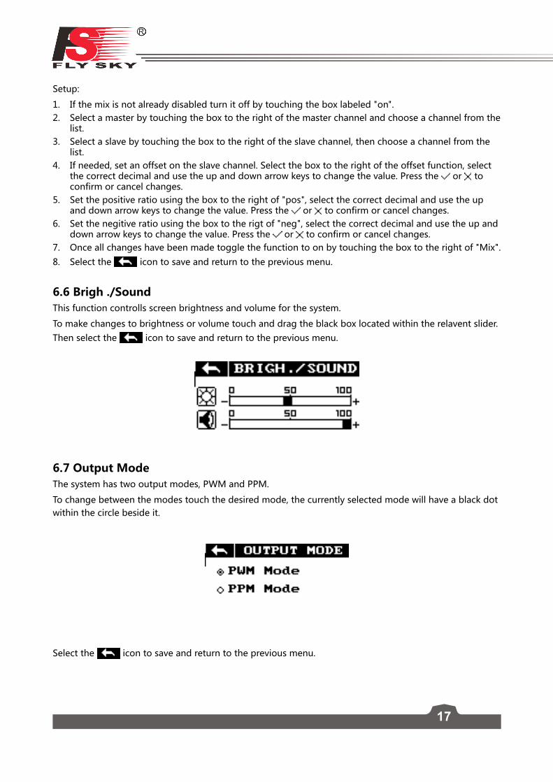
6.6 Brigh ./SoundThis function controlls screen brightness and volume for the system.
To make changes to brightness or volume touch and drag the black box located within the relavent slider. Then select the icon to save and return to the previous menu.
6.7 Output ModeThe system has two output modes, PWM and PPM.
To change between the modes touch the desired mode, the currently selected mode will have a black dot within the circle beside it.
Select the icon to save and return to the previous menu.
18
FS-l6SDigital proportional radio control system
6.8 Sticks ModeThe system has 4 stick modes to change from, to change the mode touch M1, 2, 3 or 4 on the right hand side of the screen. The currently selected mode is highlighted in black.
Left stick• Left/Right: Aileron• Up/Down: ThrottleRight stick• Left/Right: Rudder• Up/Down: Elevator
6.9 Factory Reset This function resets all settings back to default. To reset the system touch "Factory Reset" in the main menu then when prompted touch "Y" for yes.
Note: Once reset all user settings will be lost.
6.10 Firmware UpdateTo update the systems firmware:
1. Download the latest firmware from www.flysky-cn.com.2. Open the firmware update on a computer and connect the system via usb cable. 3. Select "Firmware Update" from the systems function menu. The system will show a prompt, "This will
enter firmware update mode and halt other functions" with an option to continue, select "Y". When in update mode the screen will turn off.
4. Once the system has been recognised by the computer select the update button at the bottom of the firmware update software.
Once the system has been updated it will restart. Once the system has restarted it is safe to remove the USB cable.
6.11 Receiver updateIf no receiver is connected it will wait for the receiver to connect. Once a receiver is connected select yes to update receiver. When the receiver is connected select "Y" to continue. After the update the receiver will restart and connect.
19
6.12 About FS-i6SThis menu shows the product name, firmware version, firmware release date, hardware version and the transmitter ID.
6.13 TimersTo enter the timer function touch T1/T2 on the main screen. The system has 2 timers available, both can be assigned to a switch and have 3 different settings.
Setup:
1. Select a mode. Modes:
• Up: The up timer starts from zero and counts up.• Down: The down timer starts from a pre selected time and counts down.• D/U(Down then up): The D/U timer starts from the set time, and counts down to 0, then counts
back up.
2. If nessesary set up the pre defined time by selecting the "Setup" option. Select the correct decimal and use the onscreen arrow keys to change the value.
Channels 10Model type QuadcopterRF range 2.4055 ~ 2.475GHzBandwidth 500 KHzBand 140RF power Less then 20 dBm2.4G system AFHDS 2ACode type GFSKSensitivity 4096Low voltage alarm Yes (lower than 4.2V)PS2/USB Port Yes
Power input 4.2V - 6.0V
Antenna length 26 mm*2
Weight 410g
Dimension (Length x Width x Height) 179mm x 81mm x 161mmColor White/BlackCertificate CE0678, FCC
7.2 Receiver Specification (FS-iA6B)
Channels 6Model type Quadcopter/Fixed-wing/Helicopter RF range 2.4055 ~ 2.475 GHzBand 140RX sensitivity -105dBm2.4G system AFHDS 2ACode type GFSKPower input 4.0V - 6.5 V DCWeight 10 gAntenna length 26 mm*2Dimension (Length x Width x Height) 47mm x 26.2mm x 15 mmColor BlackCertificate CE0678, FCCi-Bus port YesData acquisition port Yes
21
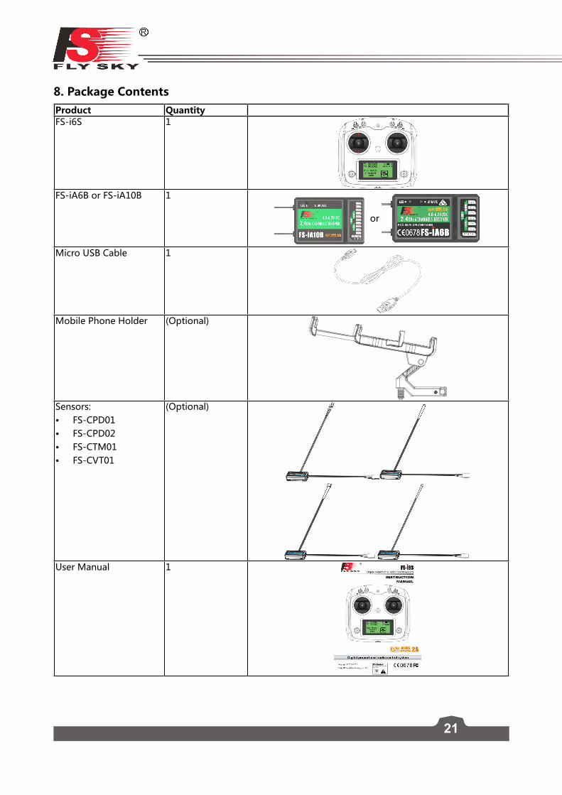
8. Package Contents Product Quantity FS-i6S 1
FS-iA6B or FS-iA10B 1
or
Micro USB Cable 1
Mobile Phone Holder (Optional)
Sensors:• FS-CPD01• FS-CPD02• FS-CTM01• FS-CVT01
(Optional)
User Manual 1
22
FS-l6SDigital proportional radio control system
9. Appendix 1 FCC Statement This equipment has been tested and found to comply with the limits for a Class B digital device pursuant to part 15 of theFCC rules. These limits are designed to provide reasonable protection against harmful interference in a residential installation. This equipment generates, uses and can radiate radio frequency energy and, if not installed and used in accordance with the instructions, may cause harmful interference to radio communications. However, there is no guarantee that interference will not occur in a particular installation. If this equipment does cause harmful interference to radio or televison reception, which can be determined by turning the equipment off and on, the user is encouraged to try to correct the interference by one or more of the following measures:
• Reorient or relocate the receiving antenna.• Increase the separation between the equipment and receiver.• Connect the equipment into an outlet on a circuit different from that to which the receiver is
connected.• Consult the dealer or an experienced radio/TV technician for help.
To assure continued compliance, any changes or modifications not expressly approved by the party responsible for compliance could void the user’s authority to operate this equipment. (Example use only shielded interface cables when connecting to computer or peripheral devices).
This equipment complies with Part 15 of the FCC Rules. Operation is subject to the following two conditions:
(1) This device may not cause harmful interference, and(2) This device must accept any interference received, including interference that may cause undesired
operation.
Caution!
The manufacturer is not responsible for any radio or TV interference caused by unauthorized modifications to this equipment. Such modifications could void the user authority to operate the equipment.