29
INSTRUCTIONS FOR OPERATIONS AND MAINTENANCE MANUALS (O&MM) FOR DEFENCE FACILITIES & INFRASTRUCTURE

INSTRUCTIONS
FOR
OPERATIONS AND MAINTENANCE MANUALS (O&MM)
FOR DEFENCE FACILITIES & INFRASTRUCTURE
DOCUMENT PROPERTIES Author Gavin Nicholls
Document Version 1.0
Status Final version
Classification OFFICIAL
Date of Issue October 2020 Document Approval
Revision History
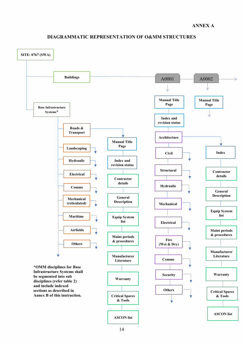
Revision Date Author Version No. Description
16.03.21 Lesley Godfrey 1.1 Amend Paragraph 32. O&MM File Naming Convention. The requirement for Infrastructure System to be included in file name now removed due to allowable character limitations.
14.05.21 Lesley Godfrey 1.2 Amend B-2 Index and Revision History, Paragraph 1b. The requirement for Infrastructure Systems O&MM to include appropriate indexation.

TABLE OF CONTENTS
GLOSSARY ............................................................................................................................... 1 INTRODUCTION ...................................................................................................................... 2 AIM OF O&MM INSTRUCTIONS .......................................................................................... 2 PURPOSE OF O&MM INSTRUCTIONS ................................................................................ 2 WHEN O&MM ARE REQUIRED............................................................................................ 2
New Buildings and Infrastructure Systems. ..................................................................... 3 Refurbishing or Changing Existing Facilities. .................................................................. 3
O&MM STRUCTURE AND CONTENT ................................................................................. 4 O&M Manual Section Headings ....................................................................................... 6 Determining O&MM Content Requirements ................................................................... 8 Resolving Disputes about Acceptable O&MM Quality ................................................... 9
O&MM FORMAT AND FEATURES ...................................................................................... 9 Format for O&MM ......................................................................................................... 10 O&MM Features and Presentation ................................................................................. 10 O&MM File Naming Convention. .................................................................................. 11 Metadata Files ................................................................................................................. 11 Multimedia Storage Devices ........................................................................................... 12
RELATED DOCUMENTS ...................................................................................................... 12 FEEDBACK ON INSTRUCTIONS ........................................................................................ 13 ANNEX A DIAGRAMMATIC REPRESENTATION OF O&MM STRUCTURES .............................. A1 ANNEX B TITLE INFORMATION ........................................................................................................ B-1 INDEX AND REVISION HISTORY .................................................................................... B-2 INSTALLER AND SUPPLIER CONTACT DIRECTORY ................................................. B-3 GENERAL DESCRIPTION AND OPERATION OF FACILITY AND EQUIPMENT ...... B-4 EQUIPMENT SYSTEMS LIST ............................................................................................ B-5 MAINTENANCE AND PERIODS AND PROCEDURES................................................... B-6 MANUFACTURER LITERATURE ..................................................................................... B-7 WARRANTY INFORMATION ............................................................................................ B-8 CRITICAL SPARE PARTS AND SPECIALIST TOOLS .................................................... B-9 AS-CONSTRUCTED DRAWINGS .................................................................................... B-10
1
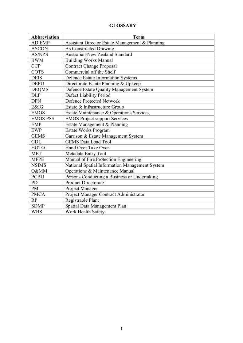
GLOSSARY Abbreviation Term AD EMP Assistant Director Estate Management & Planning ASCON As Constructed Drawing AS/NZS Australian/New Zealand Standard BWM Building Works Manual CCP Contract Change Proposal COTS Commercial off the Shelf DEIS Defence Estate Information Systems DEPU Directorate Estate Planning & Upkeep DEQMS Defence Estate Quality Management System DLP Defect Liability Period DPN Defence Protected Network E&IG Estate & Infrastructure Group EMOS Estate Maintenance & Operations Services EMOS PSS EMOS Project support Services EMP Estate Management & Planning EWP Estate Works Program GEMS Garrison & Estate Management System GDL GEMS Data Load Tool HOTO Hand Over Take Over MET Metadata Entry Tool MFPE Manual of Fire Protection Engineering NSIMS National Spatial Information Management System O&MM Operations & Maintenance Manual PCBU Persons Conducting a Business or Undertaking PD Product Directorate PM Project Manager PMCA Project Manager Contract Administrator RP Registrable Plant SDMP Spatial Data Management Plan WHS Work Health Safety
2
INTRODUCTION 1. These Instructions for Operations & Maintenance Manuals for Defence Facilities (O&MM Instructions) are provided to Defence and contracted personnel for development and regular update of the Operations & Maintenance Manuals (O&MM).
AIM OF O&MM INSTRUCTIONS 2. The O&MM Instructions provide contractors and project stakeholders with sufficient guidance and clarity to consistently and economically provide Defence with concise, simple and useful O&MMs that can be stored and accessed on Defence Estate Information Systems. 3. The O&MM Instructions also seek to ensure contractors provide Defence with WHS information necessary for Defence to discharge its duties as a person conducting a business or undertaking (PCBU) to workers and other persons under the Work Health and Safety Act 2011 (Cth) and its associated regulations (collectively WHS Legislation). 4. WHS Information for the purposes of these instructions includes manufacturer, designer, importer supplier, installer, commissioner or constructor literature and information required to be provided by the WHS Legislation and other health and safety information as required to be provided by any project contract.
PURPOSE OF O&MM INSTRUCTIONS 5. The Estate & Infrastructure Group (E&IG) O&MM Instructions apply for the development and supply of all O&MM required for operating and maintaining Defence buildings, facilities, base infrastructure systems, equipment systems and equipment. Estate works projects will generally specify the supply of new and/or updating of existing O&MMs as a project deliverable. 6. The O&MM Instructions will assist estate works contractors, Project Directors (PD), Project Manager Contract Administrators (PMCAs), Project Managers (PM) and Estate Maintenance & Operations Services (EMOS) to manage and create the required O&MM content, layout, updates and storage. For ease of information collection, reducing duplication and storage demands and improve the ongoing efficient use of O&MM information; the intention is to maximise references to applicable information available in the Defence Garrison & Estate Management Systems (GEMS), the National Spatial Information Management System (NSIMS) and manufacturer websites where applicable. 7. To improve access and ongoing administration of O&MMs, Defence only requires electronic copies of an O&MM.
WHEN O&MM ARE REQUIRED 8. All Defence buildings, facilities and infrastructure systems must have an associated O&MM. When constructing new or refurbishing existing buildings, facilities and infrastructure; an O&MM must be created or updated by the works contractor. The size and complexity of the works and status of existing manuals will significantly influence what O&MM products must be produced and supplied to Defence by a project. To determine a project’s O&MM supply requirements, the following guidelines are provided:
3
a. New Buildings and Base Infrastructure Systems. When constructing a new building or base infrastructure system, an O&MM must be produced for each building, facility and base infrastructure system (systems external to the building / facility). This will result in some O&MMs only consisting of several pages (e.g. for simple and/or small facilities) and other O&MMs comprising of several volumes (e.g. for large and complex facilities or base infrastructure systems). Further information about O&MM structure and use of volumes is detailed at paragraphs 11 to 15.
b. Refurbishing or Changing Existing Facilities. When refurbishing, replacing, upgrading or changing existing buildings and/or infrastructure systems; contractors are to check with EMOS Project Support Services (PSS) for existing O&MMs and must apply the following requirements:
(1) Where no O&MM exists, projects only need to provide an O&MM for the
buildings, base infrastructure systems and/or components relating to the project scope. This may result in the supply of an initial O&MM that only provides information for a small number of O&MM disciplines and sections. In these situations, the project must provide an O&MM document shell comprising of the manual title and index & revision pages (refer to table 1), and only the applicable discipline pages (refer to Tables 2a & 2b for a list of primary disciplines). For each applicable discipline, the sections listed in Table 3 must be used. Where the project has no applicable information for Table 3 sections, these pages are annotated as “intentionally left blank”. This enables later updating and recording of additional information associated with future projects or works. All O&MMs delivered by a project or works must comply with this instruction.
(2) Where an O&MM exists, however, it is not structured in the layout and
format specified in this instruction, projects must follow the instructions at paragraph 8b (1) above and create a new O&MM that covers the items relating to the project scope.
(3) Where an O&MM exists and it is structured in the layout and format
specified in this instruction, projects must update the existing O&MM with the information applicable to the project scope, which includes updating the index and revision status pages. This action incrementally accumulates O&MM information into one manual for each building, facility or base infrastructure system.
9. When EMOS (Project Support Service) PSS issue existing O&MMs for projects to update the contents, there will be infrequent occasions where buildings and base infrastructure systems have different projects simultaneously conducting works on the same facility or infrastructure system. EMOS PSS is to monitor the issue of manuals and project delivery schedules to coordinate the merging of updated sections, establish an oversight of version control and minimise information conflicts. 10. In addition to the requirement to produce O&MMs in accordance with this instruction, contractors must also comply, and ensure O&MMs comply, with relevant contractual, statutory and other Defence policy requirements. In particular, contractors should be aware that they maybe also required to develop other separate specialised maintenance and operation manuals or procedures in accordance with their contract, Defence policy, and other Defence manuals
4
such as the MIEE and/or statutory requirements. Examples include: Verification dossiers, High Voltage System Configuration Manual, Aeronautical Ground Lighting Configuration Manual, and Bulk Fuel Installation Consolidated Maintenance Manual etc. Where applicable, other specialised maintenance and operation manuals should be referenced in the general building and Base infrastructure system O&MMs produced in accordance with these O&MM Instructions.
O&MM STRUCTURE AND CONTENT 11. Required O&MM structure and content has been established for a number of purposes, including to require compliance with WHS and other legislative requirements, align with best industry practices, Defence and AS/NZS 1388: 1994 requirements; while reducing content that is low risk and unnecessary for facility sustainment and maintenance. Another key aim is to eliminate duplication of information that is unnecessary and/or readily available on other Defence and manufacturers' information systems e.g. GEMS, NSIMS, DEQMS, websites, or project & Estate Management (EM) folders in Objective. This means that, subject to the provision of any WHS Information, copies of commissioning test results, design & completion certificates and as-constructed drawings etc. are not required in the O&MM as they are provided as HOTO deliverables, stored in other Defence information systems in accordance with HOTO instructions and can be readily accessed by the EMOS and Defence staff when required. For example, Certificate of Completion (building occupancy certificate) will be stored in the Objective EM folder structure for each specific building. 12. To produce O&MMs that are highly suited for their intended purpose, an O&MM is to be created for each Building, Facility and Base Infrastructure System on a Defence Base or Establishment, for circumstances described in paragraph 8. Note that Base Infrastructure Systems requiring their own O&MM are those external to a building / facility e.g. the Base electrical or water networks, airfields, roads etc. Details of equipment systems internal to a building will be included in the building O&MM. Other separate but minor supporting structures associated with a major building (same design solution) can also be incorporated in the building O&MM, e.g. list the ASCONs for shelters or BBQ areas etc. How this is completed for each project requires a decision in the early stages of construction and done in consultation with the EMOS PSS and in some cases, the Resident Unit (user). All O&MMs must follow the structured layout depicted at Annex A and use the headings detailed in Tables 1 to 3 below. These sections are explained in more detail in Annex B of this instruction. 13. To ensure each O&MM section displays information with a consistent and manageable layout where later retrieval of information is intuitive and easily achieved, each manual is structured by discipline (trade) and then by section information. Tables 2a & 2b list a majority of the recognised disciplines that must be used for the O&MM. There is provision to include other applicable disciplines if they are not listed for buildings and base infrastructure systems. 14. An O&MM will comprise of Word document and other supporting information and documents saved in a folder-set that are all compressed into a “zip file”. Where all required information cannot be compiled into a single O&MM file (compressed zip file) due to file size limitations and a large amount of information, the O&MM is to be segmented into two or more clearly labelled volumes that are saved as individual O&MM files. For Building O&MMs, each volume may comprise of one or more table 2a disciplines, depending on the amount of information. Whereas for all Base Infrastructure Systems, one or more O&MM files must be used for each discipline or sub-discipline as applicable in table 2b e.g. multiple disciples are not to be documented in the same O&MM file for Base Infrastructure Systems.
5
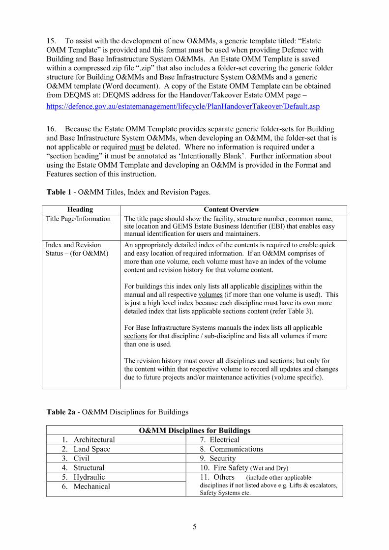
15. To assist with the development of new O&MMs, a generic template titled: “Estate OMM Template” is provided and this format must be used when providing Defence with Building and Base Infrastructure System O&MMs. An Estate OMM Template is saved within a compressed zip file “.zip” that also includes a folder-set covering the generic folder structure for Building O&MMs and Base Infrastructure System O&MMs and a generic O&MM template (Word document). A copy of the Estate OMM Template can be obtained from DEQMS at: DEQMS address for the Handover/Takeover Estate OMM page – https://defence.gov.au/estatemanagement/lifecycle/PlanHandoverTakeover/Default.asp 16. Because the Estate OMM Template provides separate generic folder-sets for Building and Base Infrastructure System O&MMs, when developing an O&MM, the folder-set that is not applicable or required must be deleted. Where no information is required under a “section heading” it must be annotated as ‘Intentionally Blank’. Further information about using the Estate OMM Template and developing an O&MM is provided in the Format and Features section of this instruction. Table 1 - O&MM Titles, Index and Revision Pages.
Heading Content Overview Title Page/Information The title page should show the facility, structure number, common name,
site location and GEMS Estate Business Identifier (EBI) that enables easy manual identification for users and maintainers.
Index and Revision Status – (for O&MM)
An appropriately detailed index of the contents is required to enable quick and easy location of required information. If an O&MM comprises of more than one volume, each volume must have an index of the volume content and revision history for that volume content. For buildings this index only lists all applicable disciplines within the manual and all respective volumes (if more than one volume is used). This is just a high level index because each discipline must have its own more detailed index that lists applicable sections content (refer Table 3). For Base Infrastructure Systems manuals the index lists all applicable sections for that discipline / sub-discipline and lists all volumes if more than one is used. The revision history must cover all disciplines and sections; but only for the content within that respective volume to record all updates and changes due to future projects and/or maintenance activities (volume specific).
Table 2a - O&MM Disciplines for Buildings
O&MM Disciplines for Buildings 1. Architectural 7. Electrical 2. Land Space 8. Communications 3. Civil 9. Security 4. Structural 10. Fire Safety (Wet and Dry) 5. Hydraulic 11. Others (include other applicable
disciplines if not listed above e.g. Lifts & escalators, Safety Systems etc.
6. Mechanical

6
Table 2b - O&MM Disciplines for Base Infrastructure Systems
O&MM Disciplines for Base Infrastructure Systems 1. Roads & Transport - Road Networks
- Car Parks - Hardstands - Walkways
5. Communications - Pit and Pipe
- Voice and Data - Engineering Services
2. Land Space - Natural Landscape
- Training Area - Buffer Zone
6. Mechanical (reticulated) - Air
- Gas - Fuel
3. Hydraulic - Potable
- Irrigation - Fire - Sewage - Stormwater
7. Maritime - Wharf & Dry-dock
- Breakwater - Beacons / Markers
8. Airfields - Runway / Taxiway
- Apron - Airfield Lighting
4. Electrical - Distribution Network
- Public Area Lighting
9. Other - (include other applicable disciplines if
not listed above) O&M Manual Section Headings Table 3 - O&MM Section Headings and Summary Content Description.
Heading Content Overview Sections Index – (For Building Discipline sections)
An appropriately detailed index of the contents is required to enable quick and easy location of required Information. For buildings this index must list applicable discipline sections as listed in Table 3. No revision history is required after this index because this requirement is covered by Table 1. For Base Infrastructure System manuals all index requirements are covered by Table 1 index, which lists all sections in Table 3 for that discipline / sub-discipline.
Installer and Supplier Contact Directory
Details the company name, trade or item supplied, company contact names (both emergency and management), phone number, email and address. This includes applicable sub-contractors.
Section 1
General Description and Operation of Facility and Equipment
For the applicable discipline, provide a general description of the facility and/or major infrastructure & equipment systems; their location, purpose and operation; while ensuring there is specific detail for any critical & unique equipment. Operation descriptions must be sufficiently detailed to enable maintenance staff to operate essential equipment and systems, where a reasonably competent person would require instructions.
Section 2
Equipment Systems List Used to record information listing all the equipment systems delivered in each building.
Section 3

7
Maintenance Periods and Procedures (including WHS Information)
Detail maintenance periods and procedures for specified equipment, fixtures and the facility fabric installed by the project. Maintenance details for all installed registerable plant and safety systems must be included in this section. Where standard maintenance requirements and periods are influenced by local environmental conditions and/or planned operating cycles, applicable changes and requirements are to be specified. All maintenance requirements and schedules specific to the design, environment and use of the facility and/or equipment, including information regarding unusual /project specific design features/features specific to use, handling or storage, should be included in Section 4.
Section 4
Manufacturer Literature (including WHS Information)
Manufacturer's literature (including WHS Information) regarding the safe and proper use, handling and storage of plant, structures and substances under the WHS Legislation and any other WHS Information required to be provided by the Contractor under the WHS Legislation or a project contract (where this information is not provided in Section 4). The provision of this information and the information in Section 4, will ensure Defence and the EMOS facilitate the safe, use, handling and storage of installed equipment and built facilities (plant and structures), including their maintenance in accordance with manufactures instructions and the appropriate use, handling and storage of substances supplied or incorporated into the installed equipment and built facilities. This is standard supporting material for the purpose of ongoing maintenance, operation and replacement of equipment and facilities. This information may include, but is not limited to, standard issue instruction booklets, maintenance and care procedures and drawings etc.
Section 5
Warranty Information Used to record copies of all collateral warranty certificates / details and specific manufacturers, installer, supplier warranty certificates.
Section 6
Critical Spare Parts and Specialist Tools
List relevant critical spare parts and specialist tools for the assets installed as part of the project. It should concentrate on spare parts that would allow Defence to operate and maintain the facility and equipment with minimum “down time”. It may also include information on spare parts suppliers.
Section 7
As Constructed Drawings This section must list all ‘As Constructed’ drawings associated with the facility / Base infrastructure system and delivered by projects, to the standard specified in the SDMP.
Section 8

8
Determining O&MM Content Requirements 17. To determine the required content for each O&MM section, the guidelines below have been established, to the maximum extent possible, to eliminate the provision of information in the O&MM that is unnecessary and/or readily available to Defence from other information systems. 18. Contractors must provide adequate maintenance and WHS information (in Sections 4 and 5, as relevant) to discharge their obligations under the WHS Legislation (and to ensure Defence can discharge its WHS duties to workers and other persons once the installed equipment and facilities are operational); including information required to be provided by designers, manufacturers, importers, suppliers, constructors, commissioners and installer under the WHS Legislation and any other WHS information the contractor is obligated to provide by its project contract. These instructions and principles underpin the additional guidance provided in Annexes A and B. 19. As a general guideline for contractors to apply when determining O&MM content (and its inclusion in Sections 4 or 5 (as relevant)), detailed maintenance information provided in an O&MM for equipment, fixtures and/or conditions includes all:
a. licenced and registerable plant, where there is a statutory requirement for
provision of operating & maintenance instructions, as per Defence Registrable Plant (RP) Technical instructions on DEQMS: https://defence.gov.au/estatemanagement/governance/Policy/EngineeringMaintenance/RegistrablePlant.asp;
b. structures and equipment relating to Defence Fuel Installations (DFI) which is
also directed by the DFI Maintenance Instructions (DFIMI); c. equipment that forms part of safety systems where there is a statutory requirement
for provision of operating & maintenance instructions, including fire safety systems, electrical, hazardous areas information;
d. any unique equipment and/or system components (including design information
specific to the equipment/system or facility); e. environmental conditions and/or planned operating cycles that necessitate a
deviation from manufacturers or supplier maintenance specification; and f. web addresses are to be provided in full for the supplier’s maintenance periods,
procedures and products relating to other low risk, general assets and fixtures, including where that information is not supplied as WHS Information (no hyper-links are to be embedded in key words).
Contractors may seek guidance from EMOS PSS if they are in doubt regarding O&MM content to be included.

9
20. The sequence for determining project O&MM requirements is depicted in Figure 1 and described in the paragraphs below.
Figure 1. Determining project O&MM requirements. 21. Design Phase. Throughout the design phase the EMOS PSS must be consulted and provide their input about facility maintenance and sustainment requirements to inform optimal design outcomes. PMCAs and PMs should leverage off this consultation to also identify if EMOS have any unique or explicit O&MM requirements for delivery in the construction phases. It is expected that these requirements can be achieved by 90% design. 22. Pre-construction. At the pre-construction phase the contractor must provide a list of the proposed O&MMs (at Building and Base Infrastructure system level) and confirm with EMOS PSS, the principles used to determine O&MM content. Additionally, the Estate Information Provision Plan must be developed for the construction contract and provide a schedule for review and feedback of O&MM deliverables (that accord to these instructions) for the project and/or associated project phase. The Contractor and/or PMCA must request, and EMOS PSS are to provide, any applicable existing O&MMs for use and/or updating if O&MMs are in a format that aligns with this instruction and specified layout. 23. Construction. Ongoing consultation between the Contractor and EMOS PSS must continue throughout the construction phase to identify opportunities to optimise the amount of provided O&MM information to a level most practical and efficient for future maintenance and sustainment; while still meeting necessary compliance and WHS requirements. The Contractor must also notify EMOS PSS when there are any variations from the approved tender design, for equipment / infrastructure systems and/or equipment (if applicable). EMOS PSS can then confirm with the contractor and PMCA / PM, any revised O&MM requirements in accordance with the O&MM Instructions (including any WHS Information required to be provided as result of the varied design). In accordance with the Defence suite of facilities contracts and HOTO requirements, draft O&MMs are to be provided to the PMCA and EMOS PSS for review by 28 day notice of completion for CFI projects or by 90% construction stage for Estate Works Program (EWP) projects. Resolving Disputes about Acceptable O&MM Quality 24. Where a disagreement about the acceptability and compliance of drafted O&MM content and structure cannot be resolved between Contractors, Project Managers, PMCAs, EMOS PSS and Zone EMP Representative; the matter is to be escalated to AD EMP for a decision about the acceptable standard. AD EMPs can seek guidance from DEPU if they have any uncertainty about the requirements detailed in these instructions.
O&MM FORMAT AND FEATURES 25. This section describes the format and features required for electronic O&MM. The required format is consistent with Australian/New Zealand Standard (AS/NZS) 1388: Guidelines for technical information for building and construction products.
90% Design Approval
Requirements agreed, if required tender documents amended
Requirements reviewed at pre-construction & baseline agreed
Review & agree changes during construction as required
EMOS liaison to inform any unique OMM requirements

10
Format for O&MM 26. The format specified in this instruction for O&MMs is consistent with best industry practices and aims to eliminate unnecessary content and/or duplicated information that is readily available from other Defence, supplier or manufacturer information systems e.g. information found on GEMS, NSIMS and/or supplier and manufacturer web-sites etc. 27. The supply of “hard copy” O&MMs are not required. This does not exclude the requirement to provide other hard copy documents where there is legislative and/or WHS requirement. These include but are not limited to: Verification Dossiers for Hazardous Areas and record files for Registrable Plant (RP) etc. (Refer to Chapter E – Technical Instruction for Management of Registrable Plant). 28. All O&MMs must be provided in word.doc format within a compressed zip file using the Estate OMM Template located on DEQMS. 29. The maximum size of an O&MM compressed zip file must not exceed 200MB in size. The O&MM must be a self-contained word document with text entries, tables and images only as necessary. Other O&MM supporting information or documents that cannot be included in the word document, such as copies of warranty certificates or Manufacturer literature documents are to be stored as individual pdf documents in the appropriate “folder-set” location within the O&MM compressed zip file and linked to the applicable section in the Word document. When referencing or linking information saved in the folder-set to the Word document O&MM, hyperlinks can be used but they must have a relative address path to the O&MM file. For documents saved in the “folder-set”, formats other than PDF are acceptable but must comply with the SDMP, e.g. formats such as Word, DWG and XLS may be used where applicable. 30. Where an O&MM compressed zip file is likely to exceed 200MB, the O&MM must be segmented into logical volumes as described in paragraphs 11 to 15 of this instruction. O&MM Features and Presentation 31. The following features for O&MM shall apply:
a. The O&MM must be in a readable and easily accessible format and presentation. The Defence standard for text is Times New Roman font, colour – black and text size - 12 pt.
b. The use of photos and inclusion of relevant reference material is encouraged to
ensure the user/reader is able to adequately understand the requirements for safe and proper operation and maintenance of the works (and to ensure, where relevant WHS Information is supplied as required by the WHS Legislation and/or any project contract). Photos must be reduced in size to <1MB and videos are not acceptable.
c. The use of manufacturer product marketing material must not occur. If necessary
contractors can provide an address to the manufacturer’s web-site for further details required by the operator or maintainer.
d. The language used in the document should be appropriate to the user or intended
audience and not contain slang.

11
e. All documents should be sized in the international A4 paper size (210 mm × 297
mm). Other larger material should be sized A3 paper size (297 mm x 420 mm). If other paper sizes are used, they should conform to the standard ISO paper sizes.
f. Every page should carry a page number. The title of the document (abbreviated,
if necessary) should appear on each page as well as the date of issue. Page numbering of attached separate documents e.g. a product booklet is not required.
g. Each section should be indicated by a heading centred on the page. h. Page margins should be: Top 20 mm, Bottom 20 mm and Sides 25mm. i. All illustrations, technical drawings, tables and charts should be clear, self-
explanatory, have descriptive titles that clearly position and correlate to referring text, instructions and notes.
j. Technical drawings should be drawn to the stated ratio scales and comply with
AS/NZS 1100: Technical Drawings. Symbols and other graphic conventions should comply with AS 1101: Graphical Symbols for General Engineering.
k. Metric (SI) units and international unit symbols should be used in technical data
and comply with AS 1000: International Systems of Units and AS 1155: Metric Units for use in the Construction Industry, except where legislation states otherwise.
l. Technical terms should be consistent with SAA HB25 and SAA HB50 or NZMP
4212. Where Defence terms, abbreviations, acronyms or initialisms are used, a glossary should be included explaining each term.
32. O&MM File Naming Convention. The following file naming convention must be used for all O&MMs to ensure nationally consistent practices (as per Defence Standards) that enable easy document storage and retrieval. The follow conventions apply:
Building: OMM_PropertyNo_PropertyName_BldingNo_BldingName_VolumeNo Example: OMM_0908_RAAF Base Williamtown_A0548_EngineRunUp_Volume1 Base Infrastructure System: OMM_PropertyNo_PropertyName_Discipline_VolumeNo Example: OMM_0908_RAAF Base Williamtown_Hydraulic_Sewage_Volume1
Handy Tip: At times, Windows may not allow the extraction of the zip folder due to a file name pathway being too long. To enable extraction of the zip folder, rename the folder before attempting a further extraction. Metadata Files 33. Each O&MM must be accompanied by a metadata file so manuals can be uploaded into NSIMS or other Defence estate information systems. The Defence Metadata Entry Tool (MET) standard is specified in the E&IG SDMP Section 5. The SDMP can be found on DEQMS or the link above. Using the MET will ensure Meta data file names are aligned to their applicable O&MM.
12
34. For MET use on the Defence Protected Network (DPN) ‘Log a Job via the ICT Self Service Portal or Helpdesk’. If the program will not install and has warnings for use on DPN the only way to address this issue is via an ICT request. 35. For MET use external to the Defence Protected Network (DPN), the tool can be accessed via the internet at: https://defence.gov.au/estatemanagement/Support/MET/Default.asp Note: Refer to the SDMP Metadata Specification Section 10.4.2. The MET tool supporting schema must be regularly updated to ensure the correct reflection of the estate. The software will automatically seek to update these, however, if required can be manually updated. See the MET tool supporting documentation on how to manually update the supporting schema.
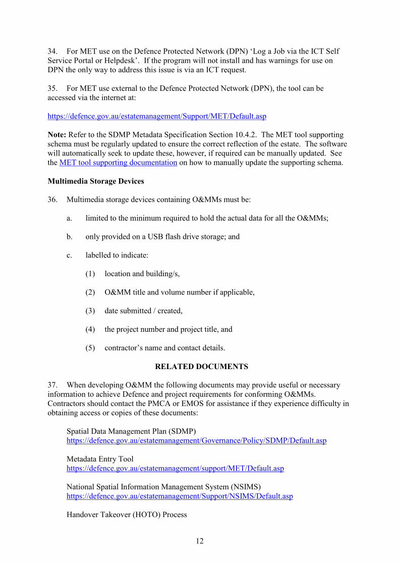
Multimedia Storage Devices 36. Multimedia storage devices containing O&MMs must be:
a. limited to the minimum required to hold the actual data for all the O&MMs; b. only provided on a USB flash drive storage; and
c. labelled to indicate:
(1) location and building/s, (2) O&MM title and volume number if applicable, (3) date submitted / created, (4) the project number and project title, and (5) contractor’s name and contact details.
RELATED DOCUMENTS
37. When developing O&MM the following documents may provide useful or necessary information to achieve Defence and project requirements for conforming O&MMs. Contractors should contact the PMCA or EMOS for assistance if they experience difficulty in obtaining access or copies of these documents:
Spatial Data Management Plan (SDMP) https://defence.gov.au/estatemanagement/Governance/Policy/SDMP/Default.asp Metadata Entry Tool https://defence.gov.au/estatemanagement/support/MET/Default.asp National Spatial Information Management System (NSIMS) https://defence.gov.au/estatemanagement/Support/NSIMS/Default.asp Handover Takeover (HOTO) Process

13
https://defence.gov.au/estatemanagement/lifecycle/PlanHandoverTakeover/Default.asp Registerable Plant – Technical Instructions (DEQMS) https://defence.gov.au/estatemanagement/governance/Policy/EngineeringMaintenance/RegistrablePlant.asp Estate Data Information website – DEQMS https://defence.gov.au/estatemanagement/lifecycle/EstateDataInformation/Default.asp Manual of Fire Protection Engineering (MFPE) https://defence.gov.au/estatemanagement/governance/Policy/EngineeringMaintenance/FireProtection/MFPE/MFPE2000.pdf Building Works Manual (BWM) https://www.defence.gov.au/estatemanagement/governance/Policy/EngineeringMaintenance/Building/Policy/BuildingWorksManual.pdf Mechanical Engineering & Maintenance – DEQMS https://defence.gov.au/estatemanagement/governance/Policy/EngineeringMaintenance/Mechanical.asp Electrical Engineering and Maintenance – DEQMS https://defence.gov.au/estatemanagement/Governance/Policy/EngineeringMaintenance/Electrical.asp GEMS Handbook - DEQMS https://defence.gov.au/estatemanagement/lifecycle/EstateDataInformation/Default.asp
FEEDBACK ON INSTRUCTIONS
38. Where incorrect information and/or suggested improvements of this instruction are identified, details should be sent to the Directorate Estate Planning & Upkeep (DEPU) using the following email address: [email protected]
14
ANNEX A
DIAGRAMMATIC REPRESENTATION OF O&MM STRUCTURES
Architecture
Civil
Structural
Hydraulic
Mechanical
Electrical
SITE: 0767 (SWA)
Buildings
Base Infrastructure Systems*
Landscaping
Roads & Transport
Electrical
Hydraulic
Fire (Wet & Dry)
Index and revision status
Manual Title Page
Comms
Mechanical (reticulated)
Comms
Security
Others
Contractor details
General Description
Equip System list
Maint periods & procedures
Manufacturer Literature
Warranty
Critical Spares & Tools
ASCON list
Maritime
A0001 A0002
Manual Title Page
Contractor details
General Description
Equip System list
Maint periods & procedures
Manufacturer Literature
Warranty
Critical Spares & Tools
ASCON list
Index and revision status
Manual Title Page
Index
Airfields
Others
*OMM disciplines for Base Infrastructure Systems shall be segmented into sub disciplines (refer table 2) and include indexed sections as described in Annex B of this instruction.

ANNEX B TO OM&M INSTRUCTIONS
TITLE INFORMATION
1. Each O&MM shall have the following title information:
a. Building Number and Functional Name. The assigned building number and name by which the facility, system and/or structure is commonly known and easily identified: e.g. Building 22 – 1st Brigade Headquarters.
b. Location Name. The name of the Defence base or establishment on which the
facility, system and/or structure is located: e.g. Robertson Barracks, Northern Territory.
c. GEMS EBI. GEMS Estate Business Identifier, e.g. 12000/B0101
d. O&MM Initial Author. The author or organisation responsible for creation
of the Initial O&MM: e.g. Builder and or sub-contractor. e. Date. The date when the initial O&MM was created. f. Other Information. Other relevant information that will assist the reader to
use the O&MM and may also include appropriate photograph, and the like such that the key information above is clear, readable and able to be understood.

B-2
INDEX AND REVISION HISTORY
1. All O&MMs must have a detailed index of the contents to enable quick and easy location of information. This requirement (outlined below) is most critical where a large O&MM comprises of several volumes due to file size limitation and an extensive amount of information:
a. Building O&MM. This index must list applicable disciplines within the manual and each discipline must then have its own index to list the applicable sections.
b. Base Infrastructure Systems O&MM. This index must list all applicable sub-disciplines and each sub-discipline must then have its own index/table of contents to list all applicable sections
2. The revision history is to record O&MM updates and changes that may occur due to other future projects and/or major maintenance activities. It is important to record any project title and number details in this section to readily identify and locate other complementary information e.g. HOTO related information. A sample revision status table is provided below. Revision History
Revision Date
Author
(company name) Project Name & Number Description of Revision
Dec 18 Builder 1 HMAS Stirling Redevelopment Project – 3A
Initial version
Nov 19 EMOS Security System Extension – EST20079
Security Vol 4, Amendments to Sections 1, 2, 3, 4, 6 & 8.
B-3
SECTION ONE
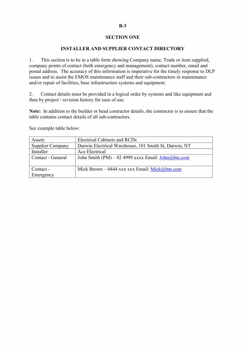
INSTALLER AND SUPPLIER CONTACT DIRECTORY 1. This section is to be in a table form showing Company name, Trade or item supplied, company points of contact (both emergency and management), contact number, email and postal address. The accuracy of this information is imperative for the timely response to DLP issues and to assist the EMOS maintenance staff and their sub-contractors in maintenance and/or repair of facilities, base infrastructure systems and equipment. 2. Contact details must be provided in a logical order by systems and like equipment and then by project / revision history for ease of use. Note: In addition to the builder or head contractor details, the contractor is to ensure that the table contains contact details of all sub-contractors. See example table below: Assets Electrical Cabinets and RCDs Supplier Company Darwin Electrical Warehouse, 101 Smith St, Darwin, NT Installer Ace Electrical Contact - General John Smith (PM) – 02 4999 xxxx Email: [email protected]
Contact - Emergency
Mick Brown – 0444 xxx xxx Email: [email protected]

B-4
SECTION TWO
GENERAL DESCRIPTION AND OPERATION OF FACILITY AND EQUIPMENT Related Maintenance Manuals 1. A list of other related manuals must be referenced in the general description to aid in the safe and compliant operation, maintenance and repair of a facility e.g. Verification dossiers, HV System Configuration Manual, Aeronautical Ground Lighting Configuration Manual, and Defence Fuel Installation Consolidated Maintenance Manual etc, as applicable. General Description 2. The general description is exactly that, a general description of the total integrated facility, infrastructure and equipment systems, their location, purpose and operation; while ensuring there is specific detail for any critical and unique equipment and reference is made to other related manuals that provide key maintenance, operation and safety information. The aim is to assist maintenance staff with safe and compliant operation, maintenance and repair of a facility. This is not to be a substitute or replication of the “Facility User Guide”, which is aimed to assist facility occupants with simple day to day operation of equipment and the facility. An example is:
Potable Water Supply
The Potable water supply is reticulated through Building “xyz” using a series of Table “B” Copper piping. The connection into the main supply has been made via a tapping band directly in front of the Fire Sprinkler room. The valve for this connection has been marked by a cast iron valve cover set in the concrete. This supply then runs to the fire sprinkler room where a second isolation (gate valve), and pressure limiting valve and strainer are located. Termination of potable water at all hospitality and industrial equipment has been made via a lever arm ball valve of pre-nominated size located on the wall behind each appliance. Termination at domestic appliances is via a half inch mini ball-o-fix valve located directly below each fixture location.
Operation Description 3. A description of facility, systems and equipment operation are only required for:
a. unique and/or intricate equipment and systems;
b. where variations to a standard build / installation would not be readily identified or understood by competent or licenced maintenance personnel;
c. enabling facility maintainers to operate essential facility fixtures and systems,
where a reasonably competent person would require instructions;
d. where the relevant WHS Information does not contain the facility, systems and equipment operation description; and
e. where special safety and/or licencing requirements exist for systems and
equipment operation (e.g. over-head gantry crane).

4. Operation descriptions should include diagrams and examples of graphics to assist the maintainer whilst operating the system and/or equipment and could make reference to applicable ASCON drawings, training material, safety & isolation devices and their locations. Descriptions should also include safety and trouble-shooting instructions to assist in solving problems to prevent expensive call outs. 5. Contractors can liaise with the EMOS throughout the construction phase to assist in determining and optimise what items require an operation description to be detailed in this section.

B-5
SECTION THREE
EQUIPMENT SYSTEMS LIST 1. The Section is a reference guide for all equipment systems installed in the building / facility. Information provided in this section shall be in table form for easy reference and overview of the various equipment systems installed in each building / facility. The listed equipment systems must have Estate Class Identifier (ECID) and Estate Business Identifier (EBI) information as this provides the maintainer sufficient information to check GEMS for more detailed physical and functional information and related equipment. 2. Further information about the different types of equipment systems and applicable GEMS ECIDs can be found in the Estate Register Information Model (ERIM). Assistance can also be obtained from the EMOS project support staff.
Equipment Systems List Estate Class Identifier
(ECID) Estate Business Identifier
(EBI) Item Description and Location
ES.EL.D 1200/B0101-GF Electrical Distribution System, Ground Floor ES.EL.D 1200/B0101-01 Electrical Distribution System, Level 1
.
B-6
SECTION FOUR
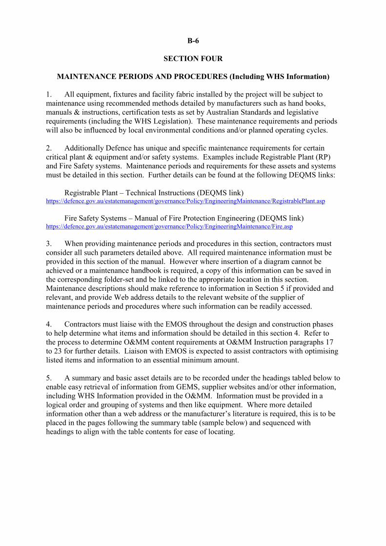
MAINTENANCE PERIODS AND PROCEDURES (Including WHS Information) 1. All equipment, fixtures and facility fabric installed by the project will be subject to maintenance using recommended methods detailed by manufacturers such as hand books, manuals & instructions, certification tests as set by Australian Standards and legislative requirements (including the WHS Legislation). These maintenance requirements and periods will also be influenced by local environmental conditions and/or planned operating cycles. 2. Additionally Defence has unique and specific maintenance requirements for certain critical plant & equipment and/or safety systems. Examples include Registrable Plant (RP) and Fire Safety systems. Maintenance periods and requirements for these assets and systems must be detailed in this section. Further details can be found at the following DEQMS links:
Registrable Plant – Technical Instructions (DEQMS link) https://defence.gov.au/estatemanagement/governance/Policy/EngineeringMaintenance/RegistrablePlant.asp
Fire Safety Systems – Manual of Fire Protection Engineering (DEQMS link)
https://defence.gov.au/estatemanagement/governance/Policy/EngineeringMaintenance/Fire.asp 3. When providing maintenance periods and procedures in this section, contractors must consider all such parameters detailed above. All required maintenance information must be provided in this section of the manual. However where insertion of a diagram cannot be achieved or a maintenance handbook is required, a copy of this information can be saved in the corresponding folder-set and be linked to the appropriate location in this section. Maintenance descriptions should make reference to information in Section 5 if provided and relevant, and provide Web address details to the relevant website of the supplier of maintenance periods and procedures where such information can be readily accessed. 4. Contractors must liaise with the EMOS throughout the design and construction phases to help determine what items and information should be detailed in this section 4. Refer to the process to determine O&MM content requirements at O&MM Instruction paragraphs 17 to 23 for further details. Liaison with EMOS is expected to assist contractors with optimising listed items and information to an essential minimum amount. 5. A summary and basic asset details are to be recorded under the headings tabled below to enable easy retrieval of information from GEMS, supplier websites and/or other information, including WHS Information provided in the O&MM. Information must be provided in a logical order and grouping of systems and then like equipment. Where more detailed information other than a web address or the manufacturer’s literature is required, this is to be placed in the pages following the summary table (sample below) and sequenced with headings to align with the table contents for ease of locating.

Summary of Maintenance Information Estate Class
Identifier (ECID) Estate Business Identifier (EBI)
Item Description Manufacturer Maintenance Information Location
ES.EL.D 1200/B0101-GF Electrical Distribution System
Maintenance information described in Section 4 below
ES.EL.EE 1200/B0101-GF Emergency and Exit Lighting System
Manufacturer literature Section 5

B-7
SECTION FIVE
MANUFACTURER LITERATURE (Including WHS Information)
1. Copies of manufacturer literature that is required to assist Defence with the ongoing maintenance and operation of installed equipment and built facilities, including that required to be supplied under the WHS Legislation and Defence Contracts (WHS Information), is to be referenced in this section of the manual (which is not supplied in Section 4). 2. The type of information and literature includes, but is not limited to, standard instruction booklets, maintenance and care procedures and drawings. Technical data required for maintenance should be referred to through the maintenance plan or accessed through a separate library or web-site. 3. Where applicable all literature and information (including WHS Information) must be detailed either in this section after the summary list of manufacturer literature or provided as a pdf document in the dedicated manufacturer literature folder-set and/or referenced with a web address to the relevant location in the manufacturer’s web-site where applicable. 4. To reduce over-sizing O&MMs, literature and/or booklets, including WHS Information, must be exported to pdf (not colour scanned) and saved in a folder titled “manufacturer literature” within the O&MM folder-set. 5. Copies of literature and information (including WHS Information) provided in the following pages or referenced to a manufacturer web-site must be preceded by summary list of manufacturer literate covered by this manual. Listed items must be provided in a logical order and grouping of systems and then like equipment. The table below provides an example summary item list. 6. Contractors must liaise with the EMOS throughout the design and construction phases to help determine what information should be detailed in Sections 4 and 5. Note: Warranty details and certificates are not to be placed in this section 5 as literature or information.
Summary list of Manufacturer Literature (including WHS Information) Estate Class
Identifier (ECID)
Estate Business Identifier (EBI)
Item Description Manufacturer Literature
ES.EL.D 1200/B0101-GF Electrical Distribution System, ABC123
Document title / description. Link to folder-set.
ES.EL.EE 1200/B0101 Emergency and Exit Lighting System
ACDC Emergency and Exit Lighting – Maintenance Hand Book, 2019 edition. Link to folder-set.
Web address

B-8
SECTION SIX
WARRANTY INFORMATION 1. A copy of all manufacturers, installer, supplier and collateral warranty certificates / details for the built and installed assets must be inserted in this section. This includes a copy of Project Collateral Warranty notifications supplied in accordance with Annexure 1 – Estate Information, of the suite of Defence facilities contracts. (Head construction contract). 2. This includes warranties for all structures, plant and equipment, fixtures and fittings. Copies of certificates must be logically grouped by systems and then like equipment, and this section must be preceded with a summary list of inserted warranty certificates for ease of locating. 3. Note that only a copy of the warranty certificates and excerpt of the applicable discipline project collateral warranty notification (sample below) is required because other basic warranty data is also recorded in GEMS via the GEMS Data Load (GDL) tool. Refer to the GEMS handbook for details about submission of warranty data via GDL. 4. Copies of warranty certificates are to be preceded by a summary list of certificates provided in the manual.
DEQMS link to GEMS Handbook: https://defence.gov.au/estatemanagement/lifecycle/EstateDataInformation/Default.asp
Sample of Project Collateral Warranty Notification Description Minimum Warranty Period (from the date
of completion of the works or the stage) Access Floor [INSERT] years Aircraft Aprons, Flexible and Rigid Pavements and Seals
[INSERT] years
Benches and Cupboards and Associated Joinery
[INSERT] years
Carpentry [INSERT] years Carpet [INSERT] years Communications Systems [INSERT] years Concrete Toppings and Repairs [INSERT] years Drainage [INSERT] years Doors [INSERT] years Electrical Services [INSERT] years
Summary List of Warranty Certificates Asset or Item, Model or Serial number Warranty Provider Electrical distribution Cabinet, XX-AB 134 Electrical Warehouse 100A Circuit Breaker, CB-415V-100A ABC Industries

B-9
SECTION SEVEN
CRITICAL SPARE PARTS AND SPECIALIST TOOLS 1. Some contracts specify that a certain number of critical spare parts and specialist tools are to be supplied by the subcontractor. All of these parts as well as a recommendation of other parts that should be kept for business continuity and breakdown service response are to be tabled in this section e.g. long supply lead-times. Provide as much detail as possible for spare parts for ease of future ordering. If necessary there may also be a need to include a paragraph for specific items regarding storage to maintain the life of spare parts e.g. disposable pleat filters for air plant need to be stored in a dry environment etc. 2. Contractors must liaise with the EMOS PSS throughout the construction phase to help determine what items should be detailed in this section and to determine if further instructions are required in the O&MM for the use and operation of specialist tools. Listed spare parts and tools must be provided in a logical order and grouping of systems and the like equipment. Examples are provided below:
Spare Parts List Estate Class
Identifier (ECID) Estate Business Identifier (EBI)
Description Equipment Manufacturer / Supplier Manufacturer Part Number
ES.HV.AD 1200/B0101-GF AHU – preliminary filters AHU Maker F64023 ES.HV.Es 1200/B0101-GF AHU – Fan belts AHU Maker B18024
Tools List Estate Class
Identifier (ECID) Estate Business Identifier (EBI)
Description Manufacturer / Supplier Product Number
ES.HV.AD 1200/B0101 AHU Filter extractor AHU Maker T98732

B-10
SECTION EIGHT
AS-CONSTRUCTED DRAWINGS 1. All As-Constructed (ASCON) drawings for Defence buildings, facilities and/or base infrastructure systems must comply with the SDMP and be saved in NSIMS. Consequently, there is no requirement to provide duplicate copies of ASCONs in the O&MM. An O&MM only needs to provide clearly identifiable references to ASCONs and Metadata files stored in NSIMS to enable easy retrieval and/or viewing when required. 2. The table below provides examples of the minimum applicable ASCON drawing information to be detailed in an O&MM. 3. ASCON and Metadata file naming conventions must comply with SDMP. Typically file names must succinctly summarise the information to allow users to quickly understand the drawing content. File names must include the subject of information and locality, spaces must not be used and under-scores must be used to separate text. Refer to the Specialised Data Specification sections of the SDMP for further guidance.
Required ASCON File Formats 4. All ASCON drawings must comply with the SDMP. Basic requirements for acceptance and saving ASCONs on NSIMS include: drawings are to be marked as “As Constructed” and must not include hand written or drawn content e.g. “red pen mark-ups”. Where multiple drawings/sheets are stored in a single AutoCAD window, each separate drawing shall be saved in either drawing or pdf format, and supplied in addition to the original AutoCAD drawing. 5. Further details can be found in the SDMP at the following DEQMS link: https://defence.gov.au/estatemanagement/governance/Policy/SDMP/Default.asp
Building or Asset ID
File (drawings) name NSIMS name (Metadata Title)
0703/A0020 0703_A0020_Electrical_Single Line Diagram.dwg 0703 Leeuwin Barracks - A0020 Contractor Centre – Electrical Single Line diagram,
0089/A0012 CCN_AR_E25_1311_2_0089_A0012_Room Layouts.dwg 0089 HMAS Stirling - A0012 Squash Courts and Weight Training Room – Room Layouts
0767/A5041 0767_A5041_Arch001.dwg 0767 Campbell Barracks – A5041 Battery Store – Arch Floor Plan
0967/A0222 0967_A0222_Arch_Elevations.dwg 0967 RAAF Pearce – A0222 Health Centre – Arch Elevations


