Instructor: Erol Sahin Y86 Instruction Set Architecture – SEQ processor CENG331: Introduction to Computer Systems 8 th Lecture Acknowledgement: Most of the slides are adapted from the ones prepared by R.E. Bryant, D.R. O’Hallaron of Carnegie-Mellon Univ.
Transcript
Instructor:
Erol Sahin
Y86 Instruction Set Architecture – SEQ processorCENG331: Introduction to Computer Systems8th Lecture
Acknowledgement: Most of the slides are adapted from the ones prepared by R.E. Bryant, D.R. O’Hallaron of Carnegie-Mellon Univ.
– 2 –
Instruction Set ArchitectureAssembly Language View
Processor state Registers, memory, …
Instructionsaddl, movl, leal, … How instructions are encoded as
bytes
Layer of Abstraction Above: how to program machine
Processor executes instructions in a sequence
Below: what needs to be built Use variety of tricks to make it run
fast E.g., execute multiple instructions
simultaneously
ISA
Compiler OS
CPUDesign
CircuitDesign
ChipLayout
ApplicationProgram
– 3 –
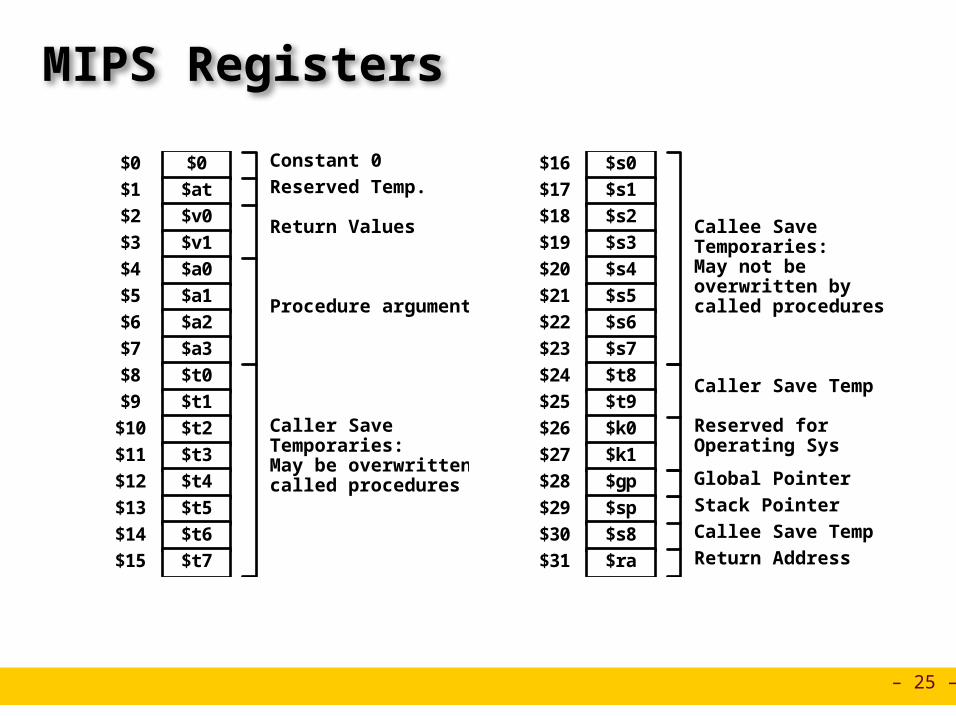
%eax%ecx%edx%ebx
%esi%edi%esp%ebp
Y86 Processor State
Program Registers Same 8 as with IA32. Each 32 bits
Condition Codes Single-bit flags set by arithmetic or logical instructions
» OF: Overflow ZF: Zero SF:Negative Program Counter
Indicates address of instruction Memory
Byte-addressable storage array Words stored in little-endian byte order
Program registers Condition
codes
PC
Memory
OF ZF SF
– 4 –
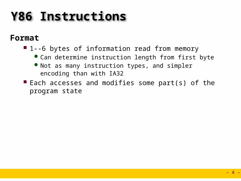
Y86 Instructions
Format 1--6 bytes of information read from memory
Can determine instruction length from first byte Not as many instruction types, and simpler encoding than with IA32
Each accesses and modifies some part(s) of the program state
– 5 –
Encoding RegistersEach register has 4-bit ID
Same encoding as in IA32
Register ID 8 indicates “no register” Will use this in our hardware design in multiple places
%eax%ecx%edx%ebx
%esi%edi%esp%ebp
0123
6745
– 6 –
Instruction ExampleAddition Instruction
Add value in register rA to that in register rB Store result in register rB Note that Y86 only allows addition to be applied to register data
Set condition codes based on result e.g., addl %eax,%esi Encoding: 60 06 Two-byte encoding
First indicates instruction type Second gives source and destination registers
addl rA, rB 6 0 rA rB
Encoded Representation
Generic Form
%eax%ecx%edx%ebx
%esi%edi%esp%ebp
0123
6745
– 7 –
Arithmetic and Logical Operations Refer to generically as “OPl” Encodings differ only by
“function code” Low-order 4 bytes in first
instruction word Set condition codes as side
effect
addl rA, rB 6 0 rA rB
subl rA, rB 6 1 rA rB
andl rA, rB 6 2 rA rB
xorl rA, rB 6 3 rA rB
Add
Subtract (rA from rB)
And
Exclusive-Or
Instruction Code Function Code
– 8 –
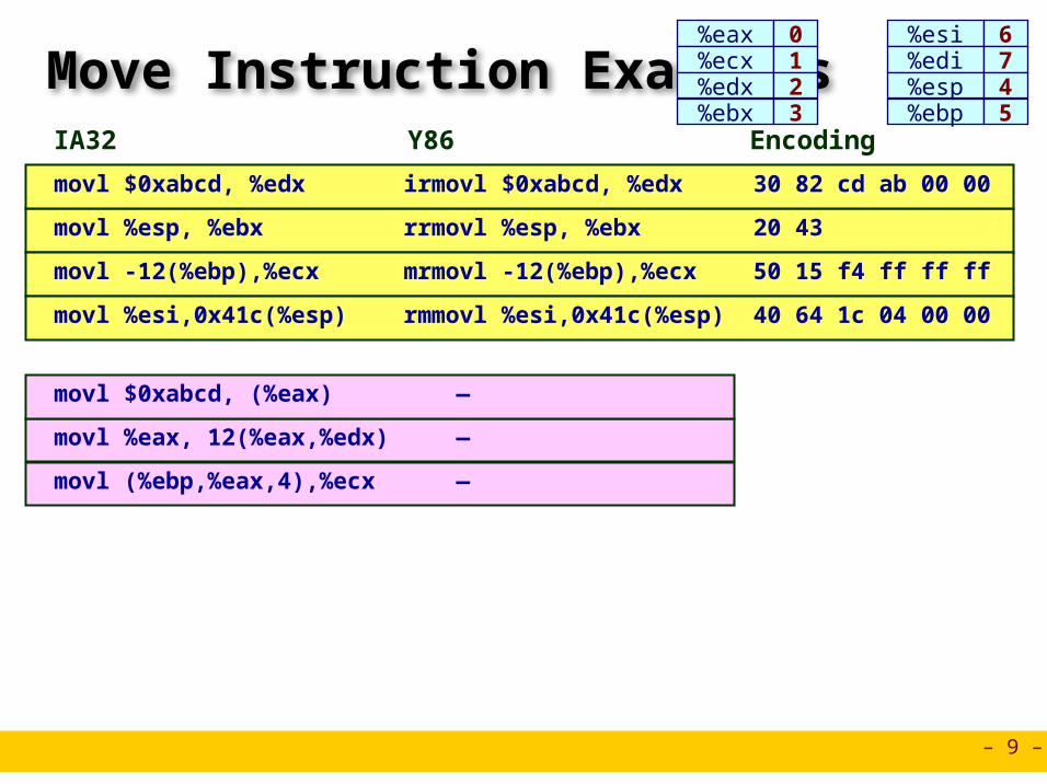
Move Operations
Like the IA32 movl instruction Simpler format for memory addresses Give different names to keep them distinct
rrmovl rA, rB 2 0 rA rB Register --> Register
Immediate --> Registerirmovl V, rB 3 0 8 rB V
Register --> Memoryrmmovl rA, D(rB) 4 0 rA rB D
Memory --> Registermrmovl D(rB), rA 5 0 rA rB D
– 9 –
Move Instruction Examples
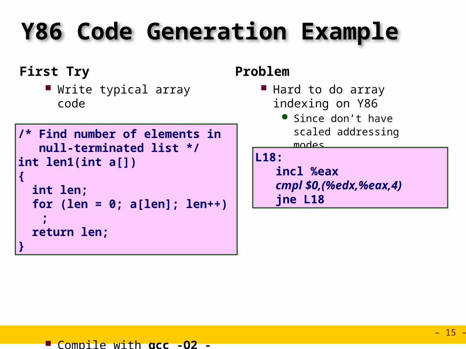
irmovl $0xabcd, %edx movl $0xabcd, %edx 30 82 cd ab 00 00
len2:pushl %ebp # Save %ebpxorl %ecx,%ecx # len = 0rrmovl %esp,%ebp # Set framemrmovl 8(%ebp),%edx# Get amrmovl (%edx),%eax # Get *ajmp L26 # Goto entry
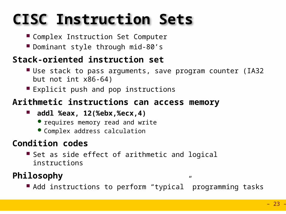
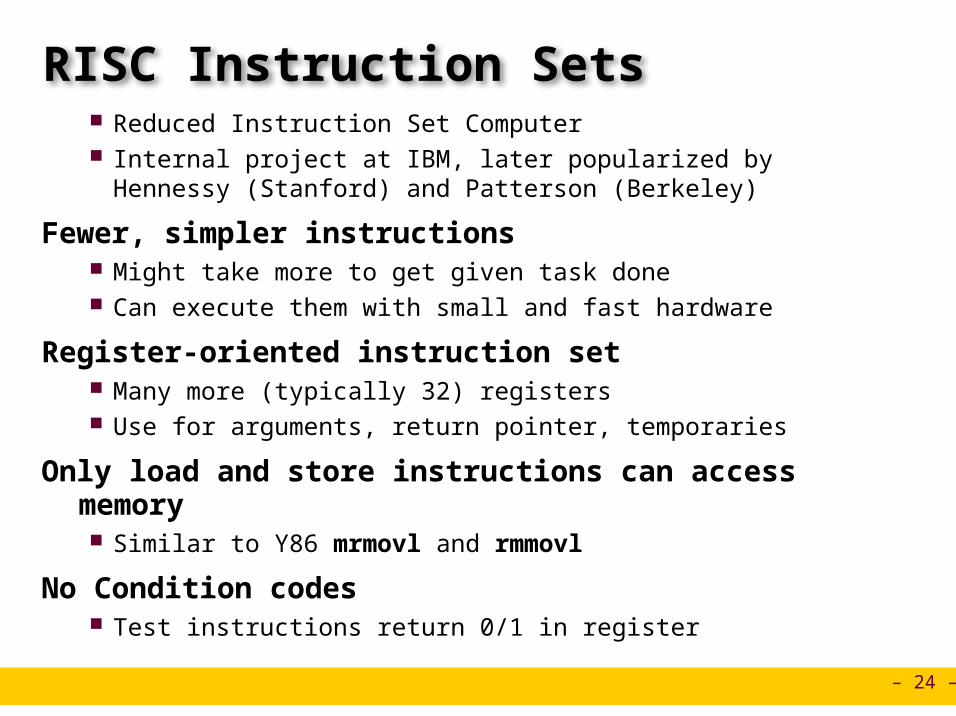
Original Debate Strong opinions! CISC proponents---easy for compiler, fewer code bytes RISC proponents---better for optimizing compilers, can make run fast
with simple chip design
Current Status For desktop processors, choice of ISA not a technical issue
With enough hardware, can make anything run fast Code compatibility more important
For embedded processors, RISC makes sense Smaller, cheaper, less power
– 28 –
Summary
Y86 Instruction Set Architecture Similar state and instructions as IA32 Simpler encodings Somewhere between CISC and RISC
How Important is ISA Design? Less now than before
With enough hardware, can make almost anything go fast AMD/Intel moved away from IA32
Does not allow enough parallel execution x86-64
» 64-bit word sizes (overcome address space limitations)» Radically different style of instruction set with explicit parallelism» Requires sophisticated compilers
Instructor:
Erol Sahin
Logic Design and HCLCENG331: Introduction to Computer Systems8th Lecture
Acknowledgement: Most of the slides are adapted from the ones prepared by R.E. Bryant, D.R. O’Hallaron of Carnegie-Mellon Univ.
– 30 –
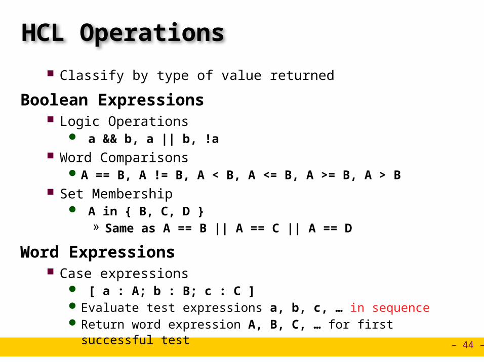
Computing with Logic Gates
Outputs are Boolean functions of inputs Respond continuously to changes in inputs
With some, small delay
ab out
ab out a out
out = a && b out = a || b out = !a
And Or Not
Voltage
Time
a
ba && b
Rising Delay Falling Delay
– 31 –
Combinational Circuits
Acyclic Network of Logic Gates Continously responds to changes on primary inputs Primary outputs become (after some delay) Boolean functions of
primary inputs
Acyclic Network
PrimaryInputs
PrimaryOutputs
– 32 –
Bit Equality
Generate 1 if a and b are equal
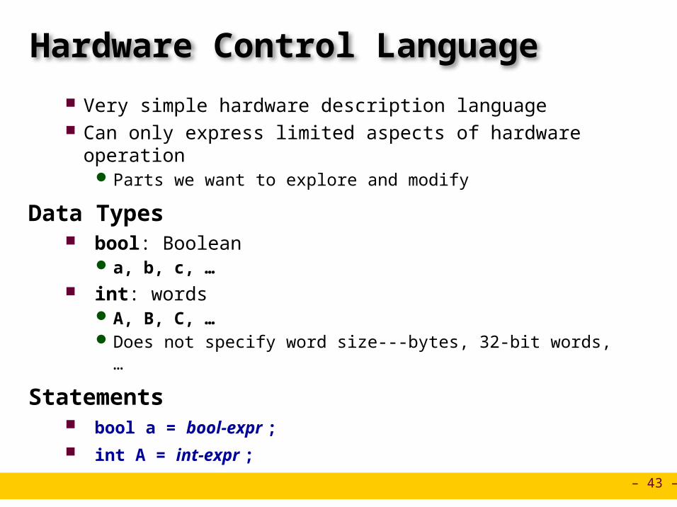
Hardware Control Language (HCL) Very simple hardware description language
Boolean operations have syntax similar to C logical operations We’ll use it to describe control logic for processors
Bit equala
b
eqbool eq = (a&&b)||(!a&&!b)
HCL Expression
– 33 –
Word Equality
32-bit word size HCL representation
Equality operation Generates Boolean value
b31Bit equal
a31
eq31
b30Bit equal
a30
eq30
b1Bit equal
a1
eq1
b0Bit equal
a0
eq0
Eq
=B
A
Eq
Word-Level Representation
bool Eq = (A == B)
HCL Representation
– 34 –
Bit-Level Multiplexor
Control signal s Data signals a and b Output a when s=1, b when s=0
Bit MUX
b
s
a
out
bool out = (s&&a)||(!s&&b)
HCL Expression
– 35 –
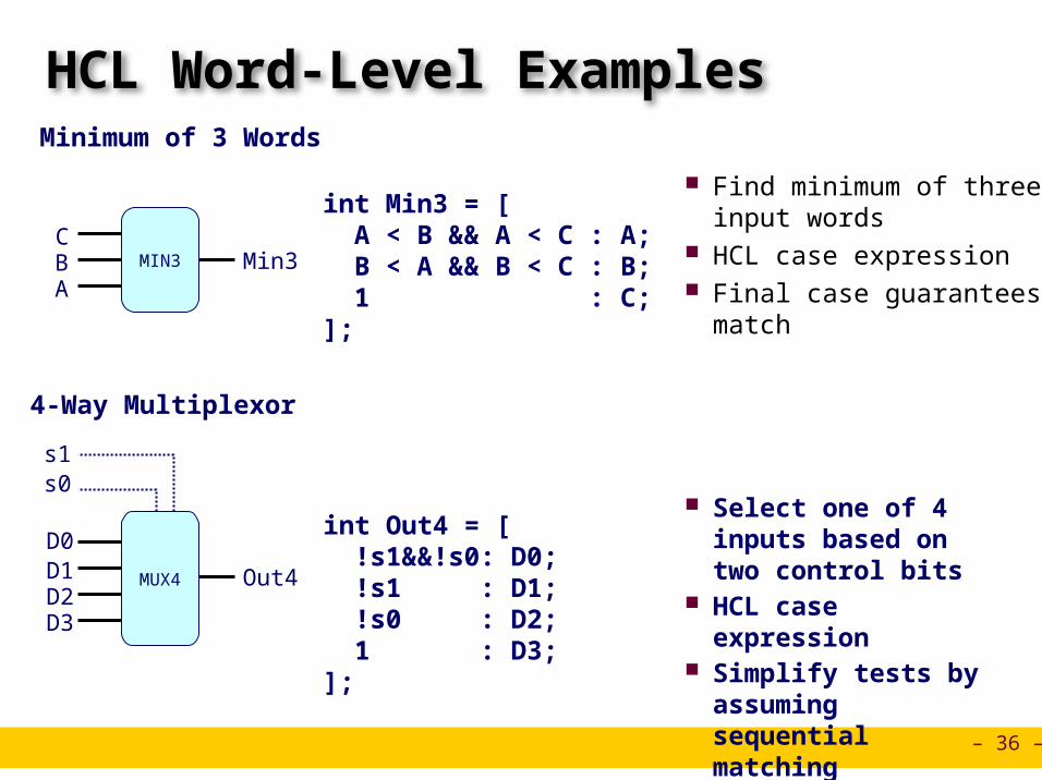
Word Multiplexor
Select input word A or B depending on control signal s
HCL representation Case expression Series of test : value pairs Output value for first successful test
Word-Level Representation
HCL Representation
b31
s
a31
out31
b30
a30
out30
b0
a0
out0
int Out = [ s : A; 1 : B;];
s
B
AOutMUX
– 36 –
HCL Word-Level Examples
Find minimum of three input words
HCL case expression Final case guarantees matchA
Min3MIN3BC
int Min3 = [ A < B && A < C : A; B < A && B < C : B; 1 : C;];
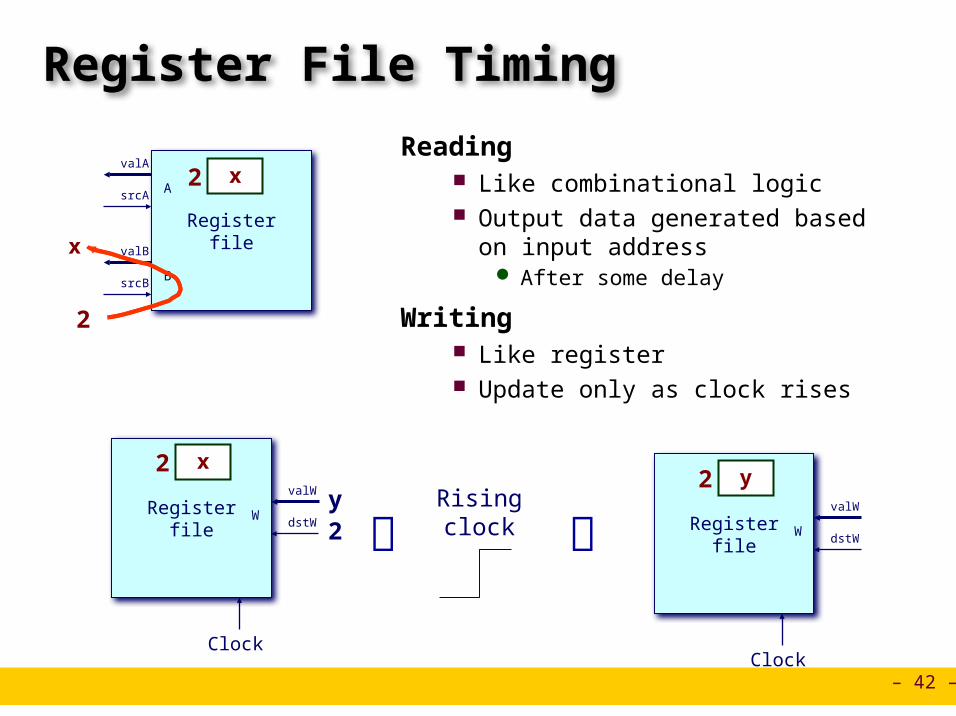
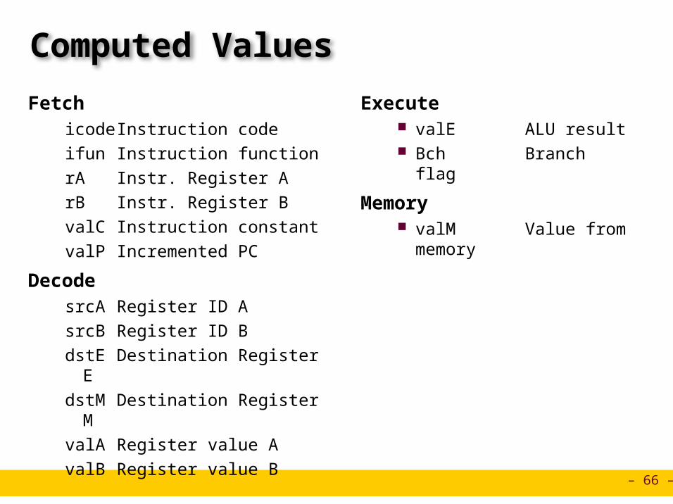
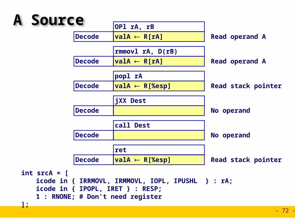
DecodesrcA Register ID AsrcB Register ID BdstE Destination Register EdstM Destination Register MvalA Register value AvalB Register value B
Execute valE ALU result Bch Branch flag
Memory valM Value from
memory
– 67 –
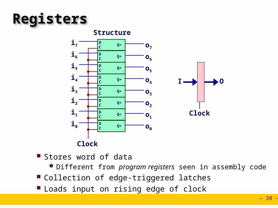
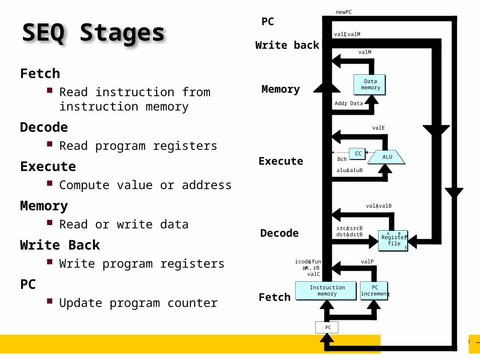
SEQ Hardware
Key Blue boxes: predesigned
hardware blocks E.g., memories, ALU
Gray boxes: control logic Describe in HCL
White ovals: labels for signals
Thick lines: 32-bit word values
Thin lines: 4-8 bit values
Dotted lines: 1-bit values
Instructionmemory
Instructionmemory
PCincrement
PCincrement
CCCC ALUALU
Datamemory
Datamemory
NewPC
rB
dstE dstM
ALUA
ALUB
Mem.control
Addr
srcA srcB
read
write
ALUfun.
Fetch
Decode
Execute
Memory
Write back
data out
Registerfile
Registerfile
A BM
E
Registerfile
Registerfile
A BM
E
Bch
dstE dstM srcA srcB
icode ifun rA
PC
valC valP
valBvalA
Data
valE
valM
PC
newPC
– 68 –
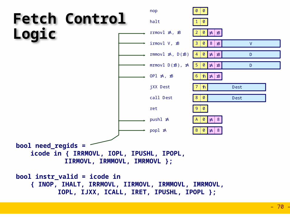
Fetch Logic
Predefined Blocks PC: Register containing PC Instruction memory: Read 6 bytes (PC to PC+5) Split: Divide instruction byte into icode and ifun Align: Get fields for rA, rB, and valC
Instructionmemory
Instructionmemory
PCincrement
PCincrement
rBicode ifun rA
PC
valC valP
Needregids
NeedvalC
Instrvalid
AlignAlignSplitSplit
Bytes 1-5Byte 0
– 69 –
Fetch Logic
Control Logic Instr. Valid: Is this instruction valid? Need regids: Does this instruction have a register bytes? Need valC: Does this instruction have a constant word?
Instructionmemory
Instructionmemory
PCincrement
PCincrement
rBicode ifun rA
PC
valC valP
Needregids
NeedvalC
Instrvalid
AlignAlignSplitSplit
Bytes 1-5Byte 0
– 70 –
Fetch Control Logic
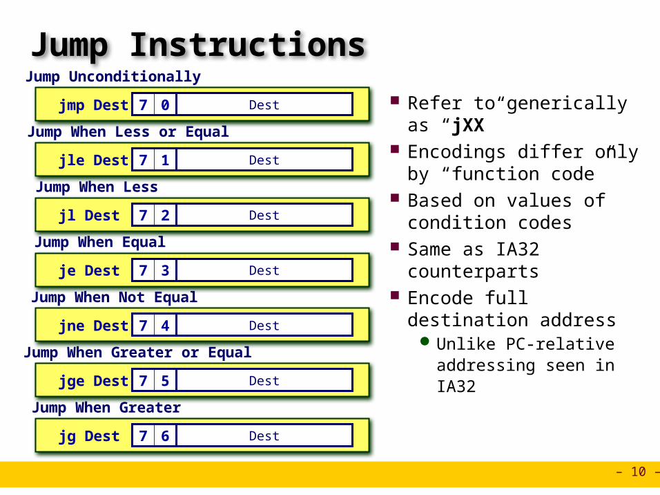
pushl rA A 0 rA 8
jXX Dest 7 fn Dest
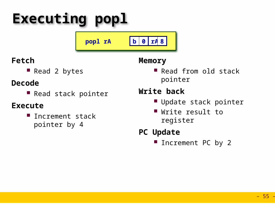
popl rA B 0 rA 8
call Dest 8 0 Dest
rrmovl rA, rB 2 0 rA rB
irmovl V, rB 3 0 8 rB V
rmmovl rA, D(rB) 4 0 rA rB D
mrmovl D(rB), rA 5 0 rA rB D
OPl rA, rB 6 fn rA rB
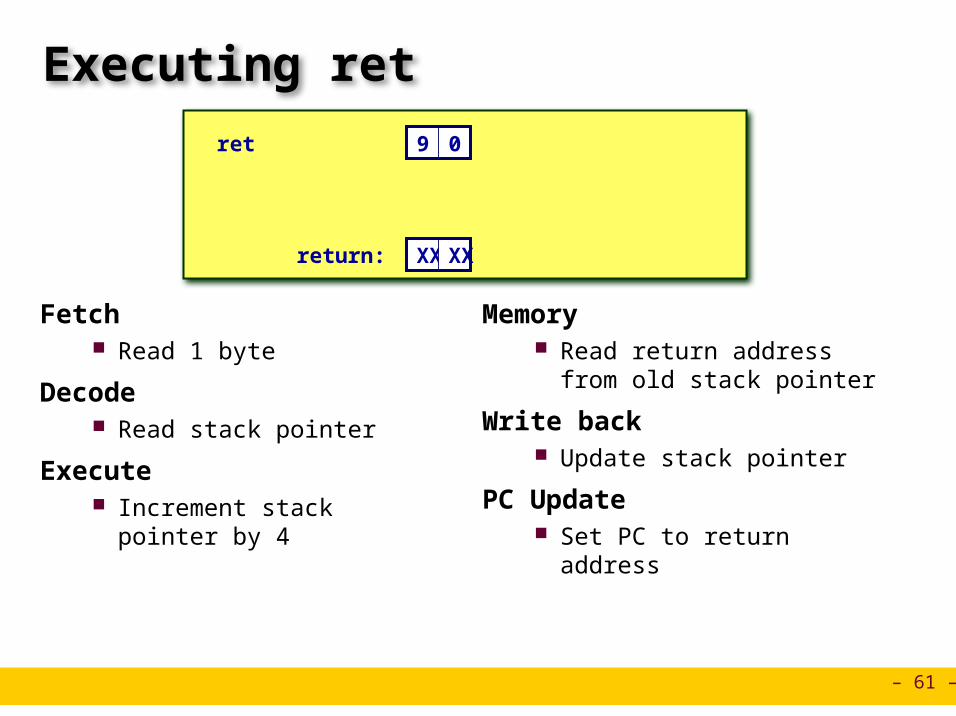
ret 9 0
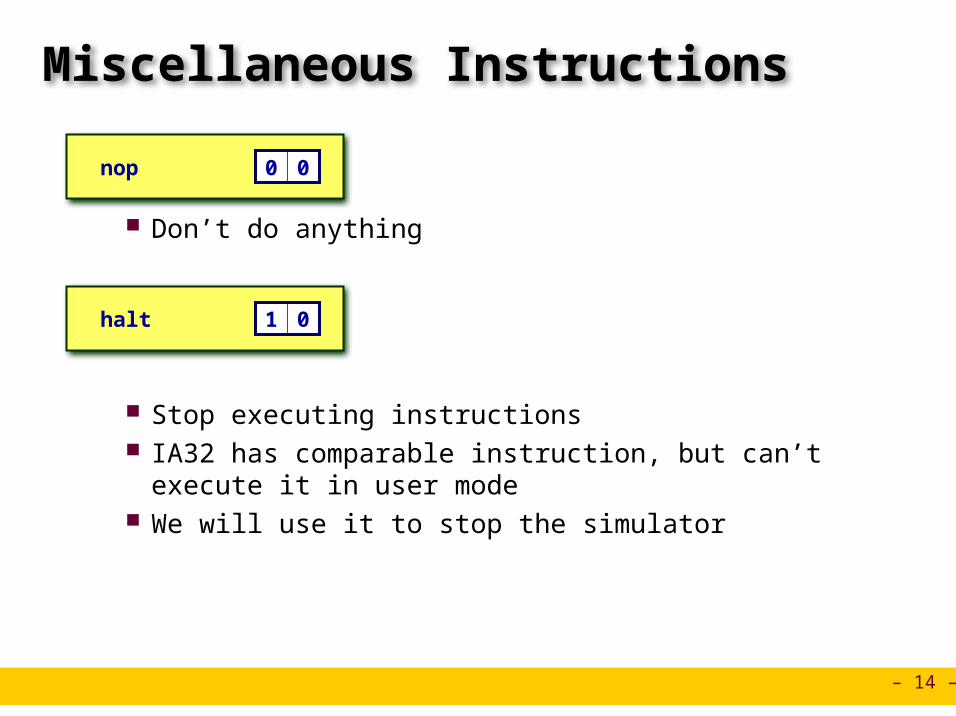
nop 0 0
halt 1 0
pushl rA A 0 rA 8pushl rA A 0A 0 rA 8rA 8
jXX Dest 7 fn DestjXX Dest 7 fn7 fn Dest
popl rA B 0 rA 8popl rA B 0B 0 rA 8rA 8
call Dest 8 0 Destcall Dest 8 08 0 Dest
rrmovl rA, rB 2 0 rA rBrrmovl rA, rB 2 02 0 rA rBrA rB
Control Logic Set CC: Should condition code register
be loaded? ALU A: Input A to ALU ALU B: Input B to ALU ALU fun: What function should ALU
compute?
CCCC ALUALU
ALUA
ALUB
ALUfun.
Bch
icode ifun valC valBvalA
valE
SetCC
bcondbcond
– 75 –
ALU A Input
valE valB + –4 Decrement stack pointer
No operation
valE valB + 4 Increment stack pointer
valE valB + valC Compute effective address
valE valB OP valA Perform ALU operation
OPl rA, rB
Execute
rmmovl rA, D(rB)
popl rA
jXX Dest
call Dest
ret
Execute
Execute
Execute
Execute
Execute valE valB + 4 Increment stack pointer
int aluA = [icode in { IRRMOVL, IOPL } : valA;icode in { IIRMOVL, IRMMOVL, IMRMOVL } : valC;icode in { ICALL, IPUSHL } : -4;icode in { IRET, IPOPL } : 4;# Other instructions don't need ALU
];
– 76 –
ALU Operation
valE valB + –4 Decrement stack pointer
No operation
valE valB + 4 Increment stack pointer
valE valB + valC Compute effective address
valE valB OP valA Perform ALU operation
OPl rA, rB
Execute
rmmovl rA, D(rB)
popl rA
jXX Dest
call Dest
ret
Execute
Execute
Execute
Execute
Execute valE valB + 4 Increment stack pointer
int alufun = [icode == IOPL : ifun;1 : ALUADD;
];
– 77 –
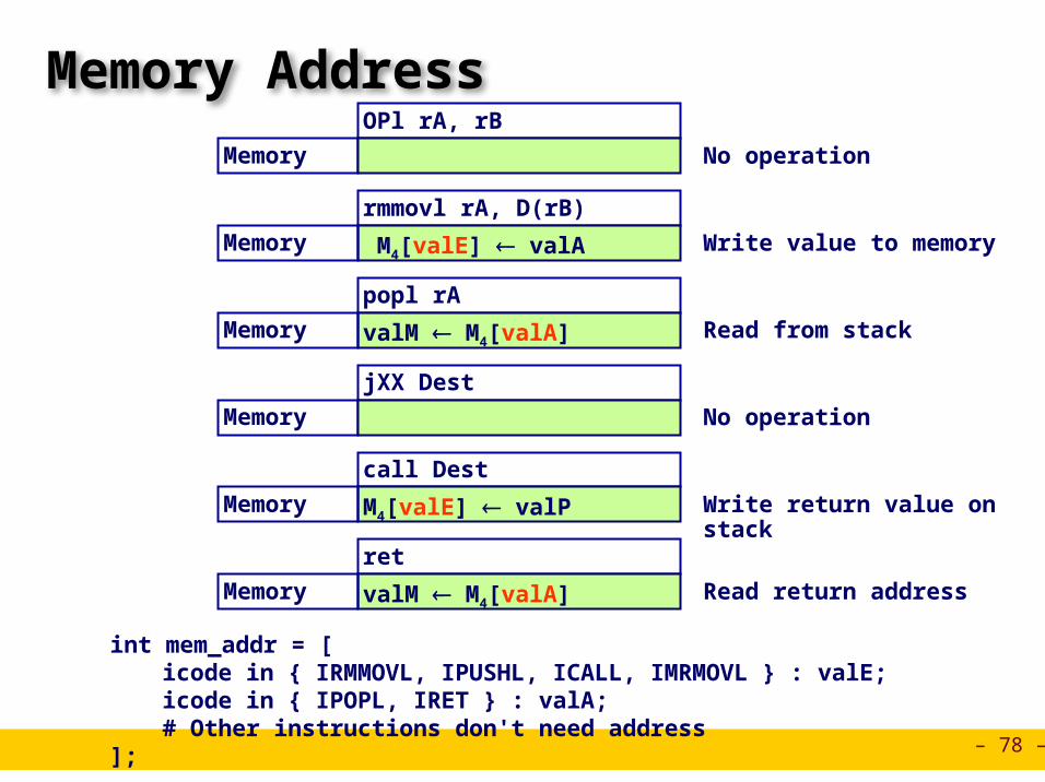
Memory Logic
Memory Reads or writes memory word
Control Logic Mem. read: should word be
read? Mem. write: should word be
written? Mem. addr.: Select address Mem. data.: Select data
Datamemory
Datamemory
Mem.read
Memaddr
read
write
data out
Memdata
valE
valM
valA valP
Mem.write
data in
icode
– 78 –
Memory AddressOPl rA, rB
Memory
rmmovl rA, D(rB)
popl rA
jXX Dest
call Dest
ret
No operation
M4[valE] valAMemory Write value to memory
valM M4[valA]Memory Read from stack
M4[valE] valP Memory Write return value on stack
valM M4[valA] Memory Read return address
Memory No operation
int mem_addr = [icode in { IRMMOVL, IPUSHL, ICALL, IMRMOVL } : valE;icode in { IPOPL, IRET } : valA;# Other instructions don't need address
];
– 79 –
Memory Read
OPl rA, rB
Memory
rmmovl rA, D(rB)
popl rA
jXX Dest
call Dest
ret
No operation
M4[valE] valAMemory Write value to memory
valM M4[valA]Memory Read from stack
M4[valE] valP Memory Write return value on stack
valM M4[valA] Memory Read return address
Memory No operation
bool mem_read = icode in { IMRMOVL, IPOPL, IRET };
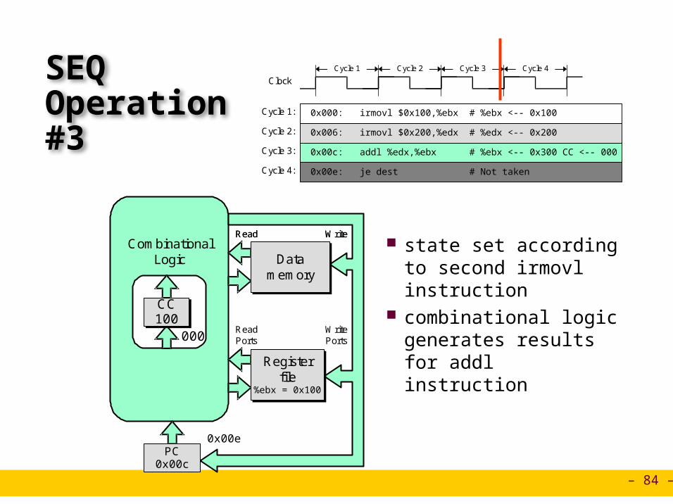
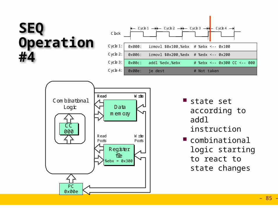
combinational logic generates results for je instruction
CombinationalLogic Data
memoryData
memory
Registerfile
%ebx = 0x300
Registerfile
%ebx = 0x300
PC0x00e
CC000CC000
ReadPorts
WritePorts
0x013
CombinationalLogic Data
memoryData
memory
Registerfile
%ebx = 0x300
Registerfile
%ebx = 0x300
PC0x00e
CC000CC000
ReadPorts
WritePorts
0x013
Read WriteRead Write
– 87 –
SEQ Summary
Implementation Express every instruction as series of simple steps Follow same general flow for each instruction type Assemble registers, memories, predesigned combinational blocks Connect with control logic
Limitations Too slow to be practical In one cycle, must propagate through instruction memory, register file,
ALU, and data memory Would need to run clock very slowly Hardware units only active for fraction of clock cycle