DOCUMENT RESUME ED 050 577 88 008 937 AUTHOR Stifle, Jack TITLE A Plasma Display Terminal. INSTWUTION Illinois Univ., Urbana. Computer-Dased Education Lab. SPON3 AGENCY Joint Services Electronics Program, Fort Monmouth, N.J. REPORT NO CERL-X-15 PUB DATE Mar 71 NOTE 33p. EDRS PRICE DESCRIPTORS EDRS Price MF-$0.65 HC-$3.29 Audio Equipment, Computer Assisted Instruction, *Computer Graphics, *Computers, *Display Systems, Electronic Equipment, *Input Output Devices, Projection Equipment ABSTRACT A graphics terminal designed for use as a remote computer input/output terminal is described. Although the terminal is intended for use in teaching applications, it has several features which make it 'iseful in many other computer tersinal applications. These features includy: a 10-inch square plasma display panel, permanent storage of information on the display screen without flicker, self-contained character and line generators, an optional random- access audio response unit, and a random-access slide projector. The terminal can send mad receive data on voice grade telephone circuits. The unit has a character-writing speed of 189 characters per second and the capability of displaying up to 2048 characters on the screen. It has a line-drasing speed of more than 600 inches per second and a character repertoire of 256 characters. The operating modes of the terminal, including commands, are explained, as are possible sources of and the output word format for terminal,generated data. (JR)
Transcript
DOCUMENT RESUME
ED 050 577 88 008 937
AUTHOR Stifle, JackTITLE A Plasma Display Terminal.INSTWUTION Illinois Univ., Urbana. Computer-Dased Education Lab.SPON3 AGENCY Joint Services Electronics Program, Fort Monmouth,
ABSTRACTA graphics terminal designed for use as a remote
computer input/output terminal is described. Although the terminal isintended for use in teaching applications, it has several featureswhich make it 'iseful in many other computer tersinal applications.These features includy: a 10-inch square plasma display panel,permanent storage of information on the display screen withoutflicker, self-contained character and line generators, an optionalrandom- access audio response unit, and a random-access slideprojector. The terminal can send mad receive data on voice gradetelephone circuits. The unit has a character-writing speed of 189characters per second and the capability of displaying up to 2048characters on the screen. It has a line-drasing speed of more than600 inches per second and a character repertoire of 256 characters.The operating modes of the terminal, including commands, areexplained, as are possible sources of and the output word format forterminal,generated data. (JR)
This work was supported in part by the Joirt Services ElectronicsProgram (U.S. Army, U.S. Navy, and U.S. Air Force) under ContractDAAB 07-67-C-0199; in"part by National Science Foundation GrantUSNSF GJ 81; is part by the Advanced Research Projects Agencyunder grant ONR Non: 3985(08); in part by Project Grant NPG-188under the Nurse TraiLing Act of 1964, Division of Nursing,Public Health Service, U.S. Dept. ci Health, Education andWelfare; cnd in dart ty th(3 State of Illinois.
Reproduction in whole or in part is permitted for any purpose :fhe United States Government.
Distribution or this report iti unlimited.
2
A PLASMA DISPLAY TERMINAL*
Jack Stifle
Coordinated Science Laboratory
and
Computer-Based Education Research Laboratory
University of Illinois, Urbana, Illinois 61801
U.S, DEPARTMENT OF HEALTH. EDUCATIONWELFARE
OFFICE OF EDUCATIONTHIS DOCUMENT HAS BEEN REPRODUCEDEXACTLY AS RECEIVED FROM THE P..RSON OAORGAPIIZAVON ORIGINATING IT POINTS OFNEW OR OPINIONS STATED DO NOT %IMESSAEULY REPRESENT OFFICIAL OfFK E 0 F EDU.CATION PCLaJTOON OR POLICY.
ABSTR1.CT
This report describes a graphics terminal designed for use as
a remote computer input-output terminal. The terminal features a
plasma display panel, self-contained character and line generators
a.d the ability to communicate over voice grade telephone circuits.
This work was supported in part by the Joint Services ElectronicsProgram (U.S. Aray, U.S. Navy, and U.S. Air Force) under ContractDAA8-07-67-C-0199; and in part by National Science Foundation GrantUSNSF GJ 81.
ACKNOWLEDGM3NTS
Several people contributed their talents to the development
of this terminal. To Ray Trogdon goes the credit for the
development of the very important panel decoding and driving
circuits. He was assisted by Jim Knoke who was responsible for
construction of these circuits.
Frank Propst and Gerrie Burr were responsible for the slide
projector and the design of the terminal enclosure.
Leonard Hedges supervised the fabrication of the terminal
electronics and was assisted in tie actual construction by George
Crawford, Fred Holy, and Rich Slr'ens.
Thanks are due Sandra Bowie, J.:!An Ciesa, and Terry Gabrielse
for their help with the publication.
TABLE OF CONTENTS iii
CHAPTER 1 - DESCRIPTION Page
1.0 INTRODUCTION 1
1.1 TERMINAL DESCRIPTION 2
1.2 AUXILIARY EQUIPMENT 5
CHAPTER 2 - OPERATING MODES
2.0 WORD FORMAT 7
2.1 CONTROL WORD 7
2.2 MODE WORD 10
2.3 MODE 0 .1
2.4 MODE 1 11
2.5 MODE 2 12
2.6 MODE 3 13
2.7 CONTROL CHARACTERS 16
2.8 ERROR CONTROL 19
CHAPTER 3 - TERMINAL GENERATED DATA
3.0 DATA SOURCES 20
3.1 OUTPUT WGAD FORMAT 20
CHAPTER 1 - DESCRIPTION
1.0 Introduction
This report describes the proposed student, terminal (remote computer
terminal), designed for use in the PLATO IV computer-based-education
system. Although the terminal is 4ntended for use in teaching applications,
it has many features which make it usefni in many other computer termthal
applications. These features include:
1. A 10-inch square plasma display panel that is readable in abrightly lighted room without e7ultrain.
2. Permanent storage of information on the display screen withoutflicker, Absolutely no refreshing of the display panel by thecomputer is required.
3. Self-contained character and line generators.
4. A character writing speed of 180 characters per second and thecapability of displaying up to 2048 characters on the screen.
5. A line drawing speed in excess of 600 inches per second.
6. A character repertoire of 256 characters, 128 of which arealterable via the computer program.
7. The ability to transmit and receive data on voice grade tele-phone circuits.
8. A random acces. elide projector for rear projection of staticinformation on the display screen.
9. Additional input-output channels for the control of auxiliaryequipment.
10. An optional random-access audio response unit.
The single most expensive item in any cathode-ray tube (CR1) display system
is the memory needed to tetresh or "hold up" on image on the face of the CRT.
As many as 4K 18-bit words of memory (1 vs) may be required to "hold up" an
image occupying as little as 2% of the available space on a display with 512
2
line resolution. a cost of 5c per bit such a memory becomes a $3600
item. Even lefore including the coats of the CRT, the digital to analog
(DA) converters, and the deflection amplifiers, all of which can easily
add up to an additional $1000, a cost level has been reached that is
prohibitive for most large users of graphic display terminals.
Fortunately, the plasma display pane11,2 with its inherent capability
storing information on the display screen eliminates entirely the costly
items mentioned above. This inherent memory and the digital nature of
the plasma panel offers for the first time the promise of !ow cost
graphical display terminale. Preliminary estimates indicate, for example,
that the terminal desctibed in this report can be produced in cuantity
for less than $2500. This terminal cost is almost 1/3 leas than the
cyst of just the memory required to operate a comparable graphical CRT display.
/I"
1.1 Terminal Description
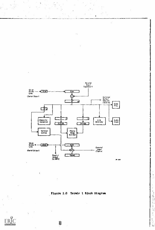
A block diagram of the prototype terminal is shown in Figure 1,0. The
terminal input section contains both a parallel and a serial input port. The
parallel port is an optional feature used mainly for engineering purposes.
At present, this port is designed to interface with a CDC 1604 Computer. The
serial input port is designed to accept data arriving at a rate of 1200
bits/second in the form of a frequency-modulated (fm) signal, which permits
1D. L. Bitzer, and H. G. Slottow, "The Plasma Display Panel - A Digitally
Addressable Display with Inherent Hemore, Proceedings, Fall Joint ComputerConterence, San Francisco, California, November 1966, p. 541.
2B. M. Arora, D. L. Bitzer, H. G. Slottow, and R. H. Willson, "The Plasma
Display Panels A New Device for Information Display and Stortte",Proceedings 8th National Symposium of the Society for Information Display,Nay 1967, p. 1.
7
VoiceGrads 14 DEM1-----Line
(Serial Input)
SIR
iVesta e ter122.1o1 or
rracode 1 1 Decode
RarollerInput
(Optional )
J
Ter= I
VolaGrade 4 ____Fron.-------t
(Serial Outps,t) I ---e4o-Lim
Pistol h1 1=CaL"alot 1Output(10 MRX)
1, --Miasma
---P POCNi512.512
EstemotOotpulChaim,(15 bit )
SlideProt.
[Line 0.644Genetcdoel Sofa
Ester rotinput
("Artist
Figura 1.0 Texan 1 Black Diagram
M. lilt
4
the terminal to operate on voice grade (Schedule 4) telephone circuits.
The terminal word size is 20 bits and therefore the terminal word rate
is 60 words per second. The terminal word format is discussed in Chapter 2.
The demodulator recovers the data from the fm signal and shifts the
data into the serial input register (SIR). Atter a full wurd has been
assembled in the SIR it is transferred to the Data (D) Rectiste.
The 20-bit D register is the distribution center of the terminal.
From this register data may be transferred to all internal sections of
the terminal as well as any external equipment connected to the terminal.
The 6 bit mode register (M) is analogous to the instruction register
in a digital computer. This register directs the Terminal. Control section
in the processing of incoming data. Terminal Control povides the
and control signals for controlling thl flLl of data within the terminal.
Four modes of operation are available and are discussed in Chapter 2.
The data it; displayed on a Digivue* Plasma Display Panel. This panel
is a 10-inch square panel containing 512 addressable points along each axis
or a total of 262,144 points. The address of any point on the panel is
specified by the contents of the 9 bit X and Y registers. The outputs of
these registers are sent to the decoding and driving circuits which drive
the display panel.
The line generator contains the circuits used in plotting lines on the
panel. Lines of any length may be drawn at the rate of 60 lines per second.
The character generator contains four 4eLories each containing the
points for plotting 64 characters or a total of 256 characters. Two of the
memories are read-only memories (ROM) and two are random access (RAH).
*Trade-mark of Owens-Illinois, Inc.
5
In the latter case the memories are loaded by the computer with special
character or graphical data as required by the terminal user. Characters
are plotted at a rate of 180 per second.
A 64 character keyboard provides the terminal operator with an input
link to the computer center. Data from the keyboard is entered into the
serial output register (SOR). From the SOR data is shifted into the
modulator where it is encoded as an fm signal for trarnuission to the
computer center.
Two additional inputs to the SOR are provided. One port permits
Terminal Control to transmit terminal condition information to the computer
while the other port provides access to the computer center for externally
connected equipment.
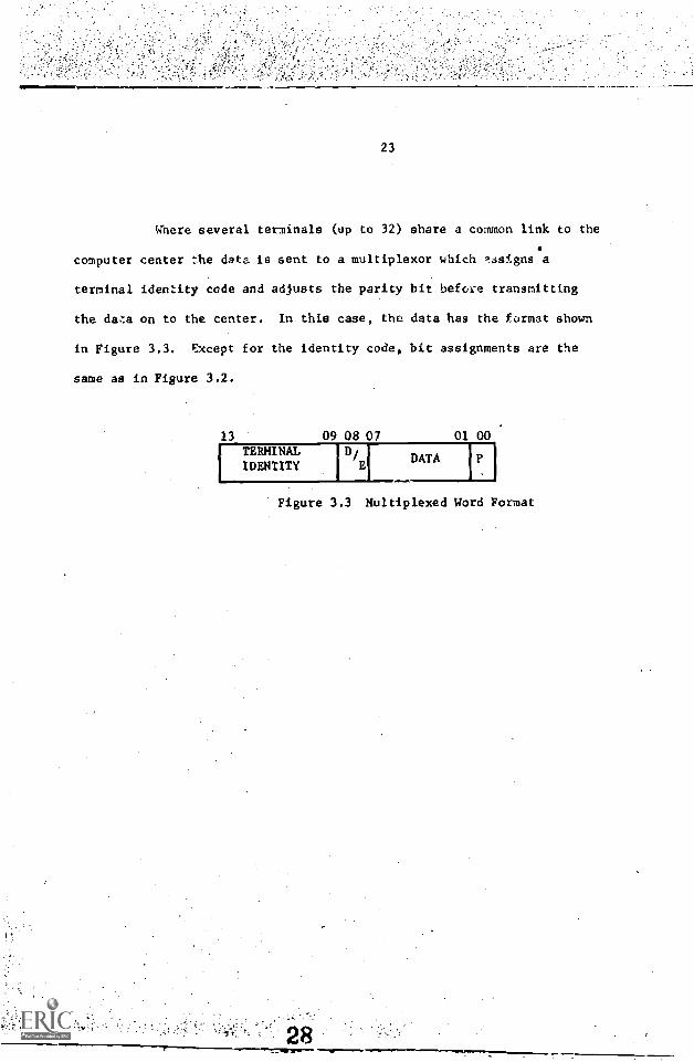
In many installations several terminals may be grouped together and
share a common link with the computer center. In such cases, data is taken
from the parallel output port on the SOR and transferred to a multiplexor
where it is encoded and transmitted to the center.
1.2 Auxiliary Equipment
Three 15 bit output channels are provided to permit operation of
external equipment.
One channel is used to transmit data to a random access slide projector
which can project slides on the rear of the plasma display panel. The slide
projector will contain a 256 slide memory with an access time of .2 second.
A second channel may be used to address an audio response unit. The
audio unit will, upon command from the computer center, play back a message
to the terminal operator. Up to 15 minutes of prereccrded audio messages
10
may be available with an average access time of .5 second. 3
Other types of equipment which might be attached to the terminal
include printers, or other hard copy devices and various types of data
acquisition and recording equipment.
3D. L. Bitter and D. Skapardas, "A Random Access Audio Device", CERL
Report X-13 (Computer -Based Bducction Research Laboratory, Universityof Illinois), (in preparation).-
7
4M1110111aMMIINIM
CHAPTER 2 - OPERATING MODES
2,0 Word Foralat
The data to be processed by the terminal consists of 20 bit words
with the format shown in Figure 2.0.
19 18 01 00
C DATA
Figure 2.0 Terminal Word Format
Bit 00 Parity bir - odd parity
Bits 01 - 18 Data
Bit 19 Control bit - 0 control word- 1 data word
Terminal words may be of two types; control words and/or data words. Data
words (C 1) contain the data to be processed by the terminal while control
words (c 0) are instructions use6 to establish certain conditions within
the terminal.
2.1 Contkol Word
The control word format is shown in Figure 2.1.
19 18 17 16 1501 00
DATA
Figure 2.1 Control Word Format
Bits ol - 15
Bits 16 - 18
12
Data
Destination of data within theterminal
8
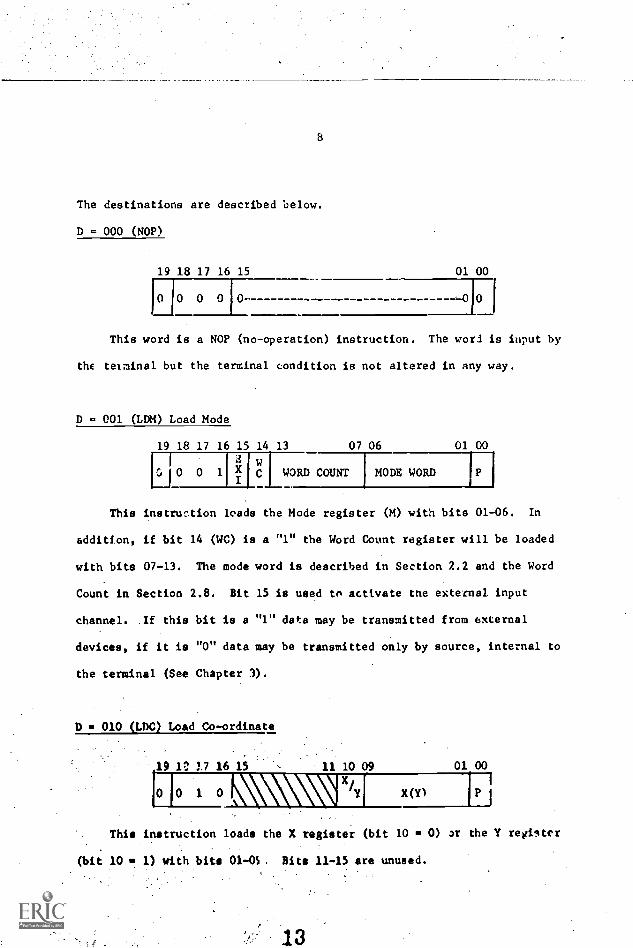
The destinations are described below.
D = 000 (NOP)
19 18 17 16 15 01 00
HO 0 0 10- 0
This word is a NOP (no-operation) instruction. The word is input by
the terminal but the terminal condition is not altered in any way.
D = 001 (LDM) Load Mode
19 18 17 16 15 14 13 07 06 01 00E w
G001XC WORD COUNT MODE WORD
This instruction loads the Mode register (M) with bits 01-06. In
addition, if bit 14 (WC) is a "1" the Word Count register will be loaded
with bits 07-13. The mode word is described in Section 2.2 and the Word
Count in Section 2.8. Bit 15 is used to activate tne external input
channel. If this bit is a "1" data may be transmitted from external
devices, if it is "0" data may be transmitted only by source, internal to
the terminal (See Chapter 3).
D 0 010 (LTA) Load Co-ordinate
19 1:: 17 16 15 11 10 09 01 00
)(Ai'Ho 1 0 x(Y)
This instruction loads the X register (bit 10 0) ar the Y register
(bit 10 1) with bite 01-05. Bits 11-15 are unused.
13
9
D = 011 (LDE) Load Echo
19 18 17 16 15 08 07 01 00r
ECHO P
This instruction loads the terminal output register (SOR) with bits
01-07. This word le then transmitted back to the computer center.
2rogramming N-Dte: This instruction should not be sent to the terminal
at a rate greater than once every 32 words. (Once every 64 words if external
J,.nput devices ar.. present at the terminal.) Exceeding this rate may cause
erroneous data to be returned to the computer center.
D - 100 (LDA) Load Me-,-.ry Address
1916 i7 .1615
1 0 0
11 10 01 00
MEMORY ADDRESS
This instruction loads the Memory Address Register (MAR) with bits
01-10. Bits 11-15 are unused. This data word specifies thn first otorage
address to be used upon entry into a Mode 2 operation. See Section 2.5.
D = 101 (SSL) Load Slide
19 18 17 16 15 01 00
0 1 0 1 SLIDE ADDRESS
This instruction is used to display a slide on the please panel. Bits
01 - 15 ere sent to the slide projector when they are used for slide addressing
ot other projector control operations.
10
D = 110 (AUD) Load Audio
19 18 17 16 15 01 00
0 1 1 0 AUDIO DATA P
This instruction is used to control the audio response unit. Bits
01 - 15 are sent to the audio unit where they may be used for message
addressing or other control operation.
D Ill (EXT) Load External Channel
19 18 17 16 15 01 00
C 11 1 1 EXTERNAL DATA
This instruction transfers bits 01 - 15 to any equipment attached to
the external output channel of the terminal.
2.2 Mode Word
For each mode of terminal operation there is an associated mode word
which directs the terminal processing of incoming data. Once placed in
any given mode the terminal remains In than: mode until receipt of a new
LDM instrucaon. The mode word format is s.iown in Figure 2.1.
06 05 04 03 02 01
M1 MO WiglW E
0
Figure 2.2 Mode Word Format
11
Bit 01 Screen Command. If this bit isa "1", the entire display panelis erased it the time the ModeWord is loaded into the M register.
Bits 02 - 03
W /E1 W /E0
X
0
Select write or erase function asfollows:
0 Erase
1 Write
1 1 Write; suppress all background eraseoperations. This operPtion is describedin more detail in Section 2.6.
Bits 04 - 05 Specify operating mode
Bit 06 This bit is unused.
2.3 Mode 00
Mode 0 is a point plotting mode. Each mode 0 data word (Figure 2.3)
specifies the address of a point on the panel to be written or erased. The
W/E bit in the mode word determines which operation is perforw2d.0
19 18 10 09 01 00
1 X Y 1P1
Figure 2.3 Mode 0 Data Word
2.4 Mode 01
Mode 1 is a line drawing mode. Each data word, Figure 2.4, specifies
the terminal coordinates of a line, the origin of which is contained in the
X and Y registers.
3.111
19 18 10 09 01 00
71-1L
Xi
Yi 1-711
Figure 2.4 Mode 01 Data Format
The terminal point of a given line is also interpreted as the origin
of the next line. Line origins may be relocated, however, by the use of
the LDC command without exiting from Mode 01.
An example of a Mode 01 operation is shown in Figure 2.5
2.5 Mode 10
Mode 2 is a load terminal memory mode. Each mode 2 data word (Figure
2.6) contains a 16 bit word to be stored in the memory location specified
by the present contents of the memory address register (MAR). Up to 1024
16 bit words may be stored in the the terminal. After the data has been stored
19 18 17 16 01 00
MEMORY DATA WORD
1:71
Figure 2.6 Mode 2 Data Word
the MAR is automatically incremented by 1. Thus, data may be stored
sequentially in memory by transmitting only Mode 2 data words. The contents
of the MAR may be changed at any time via the LDA instruction.
'The data, when displayed on the panel, appears as a vertical column
with bit 01 at the bottom and bit 16 at the top. The stored data is
displayed via Mode 3 which is described in the next section.
17
13
2.6 Mode 011
Mode 3 is a character plotting mode. The data words in this mode
contain 3-6 bit character codes as shown in Figure 2.?.
19 18 13 12 07 06
CHAR 1 CHAR 2 CHAR 3
Figure 2.1 Mode 3 Data Word
01 00
Four 64 character memories are provided in the terminal. Memories
M0 and MI are read-only memories (ROM) which contain the characters shown
in Table 2.1. Memories M2 and M3 each contain 512 words, 16 bits, the
contents of which may be loaded via Mode 2. The contents of M2 and M3
are interpreted by Mode 3 as 64 arrays of 8 x 16 bits each. Thus, a
character called from 142 or M3actually causes the contents of 8 succeeding
memory locations to be displayed on the panel.
Characters from M0
and M1are also plotted within an 8 x 16 array which
includes character and line spacing. Sea Figure 2.8.
No11usbIlIssMOOndma
Of limoBEEMI
8111.111,11111,MMMMMMMMMMessw11111
Figure 2.8 Chlracter Matrix
18
14
LDC
LDC 1 Y0
1 X1
Y1
1 X2
Y2
P
X3
Y3
x0
Y0
0 LDC 0 X4
F1
0 LDC 111 Y4
H X Y5 5 Li
0 X6
Y6
P
X4
Y4 (p
DATA
Figure 2.5 Mode 01 Example
19
X1Y1
X Y00
DISPLAY
15
BCD
CodeMO M1 M2 M3
on SPACE SPACE
01 A #
02 B $
03 C %
1'4 D ft
05 E
06 F .1-
07 G f
10 H
1.1 I -12 J
1
13 K 11
14 L
15 11 ,I.
16 N
17 0
20 P co
21 Q o
22 R -..
23 S
24 T a
25 U 13
26 V 3
27 W U
30 X 1
31 Y a
32 Z w
33
34 }
35 IA
36 ? 9
37 i. E
BCD
CodeM
0 --'M
1M2
40 0
41 a 1
42 b 2
43 c 3
44 d 4
45 e 5
46 f 6
47 g i
50 h 8
51 1 9
52 j =-
53 k =
54 1
55 m e,
56
57 0
60 p <
61 q
62 r <
63 a x
64 t *
65 u /66 v
67 w -70 x
71 y . o
72 z i
73 (
74
75
76 .
; 77 UNCOVER UNCOVER UNCOVER UNCOVER
Table 2.1 Character Codes
20
16
Character write/erase is controlled by the write/erase bite in the
mode word. If W/E0
= 1, characters are written; if W/E0
= 0, characters are
erased. If W/E1= 0, the background or normally unfilled portion of each
character matrix will be erased, if W/E1 = 1 the background remains unaltered.
Up to 32 lines of 64 characters aach may be plotted for a total of
2048 characters. In comparison, a typical page of double spaced '-Ype
consists of 27 lines of /2 characters or a total of 1944 characters.
2.7 Control Characters
The "uncover" code (77) is used to gain access to 12 r.:ntrol characters.
These characters are useful in controlling display format in Mode 3 operations.
Upon receipt of a 77 code, the terminal interprets the next character
code as a control character rather than 3 memory address. Following execution
of the control character normal Mode 3 operations are resumed. A description
of each control function is given below.
Uncover (77)
This code instructs the terminal to obey the next character address
as a control function. If several uncover codes are sent in seque.ce, the
first non-uncover code will be treated as the control character.
Backspace (101
This character decreases by 8 the panel x Address, i.e., moves one
character position to the left. A backspace over a displayed character
does not erase the character.
21
17
Tab (11)
This character increases by 8 the panel x address, i.e., moves one
character position to the right. A tab over a displayed character does
not erase the character.
Line Feed (12)
This character decreases by 16 the panel y address, i.e., moves down
one character position. A line feed over a displayed character does not
erase the character.
Vertical Tab (13)
This character increases by 16 the panel y address, i.e., moves up
one character position. A vertical tab over a displayed character does
not erase the character.
Form Feed (14)
This character sets the panel address to the upper left corner (x a 0,
y 496). This is the first character position on the top line of the
display. No displayed data is erased in this operation.
Carriage Return _(15)
This character clears (sets to 0) the panel x address and decreases
by 16 the y address. The screen address is thus set to the first character
position on the line immediately below the present line. No displayed
data is erased in this operation.
superscript ila
This character increases the panel y address by 5. All characters
received following this code appear as shoWn in Figure 2.9. This selection
nay be removed by receipt of a subscript (17) code. No data is erased in a
I libraryBoat Electronic", Laboratory CornerSu Diego, California 91132
I Trchnicel LibraryNewel Undersea Warfare Grater3201 E, Foothill BoulevardPasadena, Californle 91107
I Dr. Ruse L, Morgan (+HT)Turning lasaarch DivisionMMUS Resources LaboratoryWrietatterfion Air For." Rue1163* 46433
311 08
I Headquarters, Air Training Coana.ndRandolph Air Force Base, Tema-
78148Attu: ATRTD (Or. Neyer)
I Mr. Michael Macdonald -RossInternational Training and Education
Comf any Unite"IT-1C douse29-10 Ely PlaceLondon EC1
ENGLAND
Commanding OfficerU. S. SIVA Schools CommandHare IslandVallejo, California 90552
1 Dr. Pon C. Coombs, Assts tent DirectorERIC ClearinghouseStanton' UniversityPalo Alto. California 94305
1 CDR H. J. Connery. 051Scientific Advisory Team (Code 71)Staff, COniASSFORLItNTNorfolk, Virginia 23511
I ERIC ClearinghouseEducational Media and TechnologyStanford UniversityStanford, California
I ERIC ClearinghouseVocational and Technical EducationOhio State UniversityColumbus, Ohio 43211
1 Dr. Benton J. UnderwoodDepartment of Psychologybdrthveste re UniversityEvanston, gllinols 60291
SocurtIT.Clamsification.....--..,
,,:.-..,.-,-;..-::')':..,'- :. DOCUMENT CONTROL DATA R & DSre,roti. I fur sif iciaiIn of tithe. toady .f .h: ',A. I 0,,,I IpthAme .4,, ,/ / thy, ,,,,..t be VIM, d al,. 7, the 0 f ,...1),,.r,,,,, i . ,,,,,..111,..1,
I c.. f.:%A.,NG ac7IvItv rrorporate author) . .., .s. :.- ,.,,, - 'University of Illinois, Board of Trustees '
Computer-based Education Research LaboratoryUrbana, Illinois 61801 , i- -'