2 nd International Balkans Conference on Challenges of Civil Engineering, BCCCE, 23-25 May 2013, Epoka University, Tirana, Albania 983 Water intake structures for hydropower Dritan Bratko 1 , Alban Doko 2 1 Department of Hydraulic and Hydrotechnic, Universiteti Politeknik i Tiranes, Albania 2 Department of Hydraulic and Hydrotechnic, Universiteti Politeknik i Tiranes, Albania Abstract In the age of industrial development, lakes, rivers and canals have been exploited to an ever increasing extent, and dams and weirs for the diversion of river water have been constructed on flowing waterways for various purposes. Likewise, river intakes have been developed even further for agriculture and the generation of hydroelectric power. Now, when in the industrialized countries, particularly in Europe, this development has practically come to an end. In Albania a very big number of sites for large-scale and small-scale river water intakes are developing in the field of energy production. The exploitation of rivers and streams requires thorough planning, irrespective of whether large- scale or small-scale projects are concerned. The ecological aspects, the compatibility of a project with the environment and the minimization of subsequent damage caused by any measure taken are important planning criteria. For large-scale and small-scale projects, experienced planning engineers and experts are normally appointed. In addition to the individual types of intake structures, the necessary hydraulic and static calculation methods are given and explained. The prerequisites to be met by the intake structure are different for each river and stream, and therefore only the basics can be described here. The operativeness of an installation depends largely upon the planning and, thus, upon the experience of the planning engineer. In just such a sensitive field as the intervention in a river or stream with a view to tapping water for general purposes, a great number of criteria are to be considered, and it is these which rare given in this planning guide. Introduction Which is the most adequate layout plan for an intake structure? The most adequate layout plan is the one which allows the intake structure to function in the most effective manner while allowing the necessary amount of water at the required elevation. In this section, the design and analysis of the intake structure elements, which influence the effectiveness of conveying water to the turbine, have been treated. The purpose of hydraulic calculation for all the elements of the intake structures with or without pressure is that the designers have the possibility for optimization of the hydraulic scheme of a small hydropower plant, and water to be conveyed to the turbine with lower costs and high efficiency. Traditionaly, the intake structures for the hydropower plants were the structures conveying water from a system without pressure to one with pressure. In this study the definition of “intake structure” includes not only the traditional ones but the ones which serve to the systems without pressure as well. Intake structures can be categorized as: • Intake structures which take water directly from the water flow and pass it to the penstock.
Transcript
2nd International Balkans Conference on Challenges of Civil Engineering, BCCCE, 23-25 May 2013, Epoka University, Tirana, Albania
983
Water intake structures for hydropower
Dritan Bratko1, Alban Doko2
1Department of Hydraulic and Hydrotechnic, Universiteti Politeknik i Tiranes, Albania2Department of Hydraulic and Hydrotechnic, Universiteti Politeknik i Tiranes, Albania
Abstract
In the age of industrial development, lakes, rivers and canals have been exploited to an everincreasing extent, and dams and weirs for the diversion of river water have been constructed onflowing waterways for various purposes. Likewise, river intakes have been developed evenfurther for agriculture and the generation of hydroelectric power. Now, when in theindustrialized countries, particularly in Europe, this development has practically come to an end.In Albania a very big number of sites for large-scale and small-scale river water intakes aredeveloping in the field of energy production.The exploitation of rivers and streams requires thorough planning, irrespective of whether large-scale or small-scale projects are concerned. The ecological aspects, the compatibility of a projectwith the environment and the minimization of subsequent damage caused by any measure takenare important planning criteria. For large-scale and small-scale projects, experienced planningengineers and experts are normally appointed. In addition to the individual types of intakestructures, the necessary hydraulic and static calculation methods are given and explained. Theprerequisites to be met by the intake structure are different for each river and stream, andtherefore only the basics can be described here. The operativeness of an installation dependslargely upon the planning and, thus, upon the experience of the planning engineer. In just such asensitive field as the intervention in a river or stream with a view to tapping water for generalpurposes, a great number of criteria are to be considered, and it is these which rare given in thisplanning guide.
IntroductionWhich is the most adequate layout plan for an intake structure?The most adequate layout plan is the one which allows the intake structure to function in themost effective manner while allowing the necessary amount of water at the required elevation.In this section, the design and analysis of the intake structure elements, which influence theeffectiveness of conveying water to the turbine, have been treated. The purpose of hydrauliccalculation for all the elements of the intake structures with or without pressure is that thedesigners have the possibility for optimization of the hydraulic scheme of a small hydropowerplant, and water to be conveyed to the turbine with lower costs and high efficiency.Traditionaly, the intake structures for the hydropower plants were the structures conveying waterfrom a system without pressure to one with pressure. In this study the definition of “intakestructure” includes not only the traditional ones but the ones which serve to the systems withoutpressure as well.Intake structures can be categorized as:
• Intake structures which take water directly from the water flow and pass it to thepenstock.
2nd International Balkans Conference on Challenges of Civil Engineering, BCCCE, 23-25 May 2013, Epoka University, Tirana, Albania
984
• Intake structures which take the water through an auxiliary structure which diverts theflow• Intake structures placed on reservoirs
Design criteriaThe effectiveness of a hydropower plant is directly dependent on the location, orientation, andthe water level at the intake structure. In order to have satisfactory and correct results, thehydraulic structures should be adapted to the site. Factors that are considered include:
Water levels
In most of the cases the intake structures should be designed in order to function for differentwater levels.For the intake structures placed on reservoirs, studies should be conducted in order to determinethe fluctuations of the water level. The efficiency of the structure should be checked for thenormal and extreme levels. It can be accepted that the effectiveness of the structure may belower in the case of maximal levels if they have short time span.The intake structures placed in rivers or streams should be determined from the water level ofthe flow, which is determined by hydraulic studies. The influence of the intake structure or thediversion structure on the water levels in the river or stream, the erosion and deposition, the iceblockage etc., should be evaluated. The narrowing or widening of the river at the intake structureshould be evaluated as well.
Placement distance
The distance between the intake structure and the powerhouse influences the hydraulic losses aswell as the cost of the conveyance structures. Most of the powerhouses should be constructednear dams or diversion structures in order to profit as much as possible in water head, while theintake structures should be placed on the lowest point of the reservoirs. In the cases when thepowerhouse is at a considerable distance from the intake structure: should be done an evaluationof the whole diversion system in order to have as few losses as possible.
Geological composition
Bank stability is important, and the intake should be located in a reach of river where the bank isstable because an unstable bank is likely to adversely affect intake performance. Foundationconditions also may affect design. If possible, the intake should be located at a site possessingfavorable foundation conditions because overcoming adverse foundation conditions may requirecostly treatment.
Diverted flow
While placing the intake structure, the diverted flow should be taken into consideration. Intakesare generally oriented to minimize separation of flow which causes portions of the intake to beineffective and can result in swirl, eddies, and vorticity which may entrain air. Where the rate ofwithdrawal is small and the intake relatively deeply submerged, flow separation, vorticity, andair entrainment are less likely to occur. Higher withdrawal rates are more conducive to flowseparation than lower rates.
Sediment
2nd International Balkans Conference on Challenges of Civil Engineering, BCCCE, 23-25 May 2013, Epoka University, Tirana, Albania
985
The intake structures should be placed in such a way to minimize the accumulation of finematerials. The intake structures in reservoirs are placed over the calculated alluvial accumulationlevel for the lifetime of the structure. Sediment accumulation in the intake approach, result inhigher approach velocities, increased head losses, and potentially flow separation. Where theaccumulation is severe, removal may be required at periodic intervals. The passage of sedimentthrough the unit may result in undesirable wear of the turbine runner and this should beminimized.Ice
Ice is a major hazard for intake structures as in cases of: trash rack blockage, increase inhydraulic losses, reduction of the diverted flow, and additional measures for its cleanup. Theplacement of the intake structures in order to minimize the problem of ice requires a detailedstudy of the annual ice regime. The general principles are to locate the intake where ice flowsare minimal and to provide facilities for passing ice through the project such as ice sluices andoverflow sections or gates.
Power intake
Vertical intake
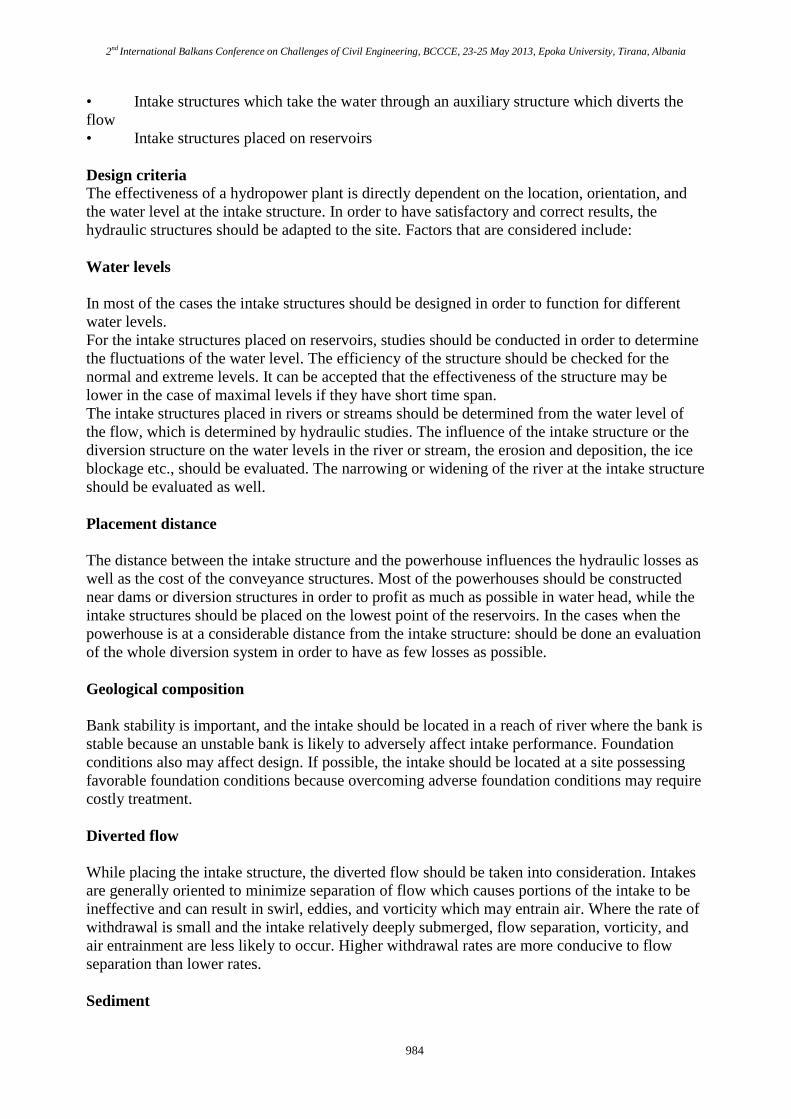
Vertical intakes are commonly used where there is a great difference in elevation between thereservoir bottom at the intake and the turbine, and where the penstock or power tunnel is verticalfor some distance to the level of the powerhouse.The dimensions of the vertical intake are conditioned from the penstock diameter or the powertunnel diameter. This diameter is determined from the comparison of the energy proficiency tothe construction cost. The main criteria for the structural dimensioning should be theminimization of the hydraulic losses and the avoidance of eddies.
a) b)
Figure 1 Vertical intake [Ref. 3]
Hydraulic losses caused by the vertical intakes:
2nd International Balkans Conference on Challenges of Civil Engineering, BCCCE, 23-25 May 2013, Epoka University, Tirana, Albania
986
2
2L
VH K
g (1)
LH hydraulic losses from the water surface level to the diametric constant of the intake (m),
V velocity in the penstock (m/s), K the loss coefficient which varies from 0.1 up to 0.3
The adequate shape of the vertical intake is as shown in the figure 1. b):The equation for the entrance shape which is derived from laboratory tests is:
1
2
1
4
0.204
a
QR
H
[Ref. 3] (2)
Q discharge (m³/s), aH distance between the water surface and the plan where we want to
determine the radius (m)
A special care should be provided in determining if trash racks will be used or not. The racks areusually placed on the outter perimeter of the structure where the flow velocity is low. Thecleanup of the trash racks is very difficult when the water depth is very high. But in these cases,problems with their blockage are not expected to occur.The hydraulic losses from the trash racks depend on the thickness of the rods, the depth and thedistance between them.
Lh trashrack head loss (m)
2
2n
L t
vh K
g (3)
nv velocity through the net trashrack area (m/s), tK trashrack loss coefficient
2
1.45 0.45 n nt
g g
a aK
a a
(4)
na net area through rack bars (m²), ga gross area of the racks and supports (m²)
An important criteria in the functionality of vertical intakes is the submerged depth whichusually is grater compared to horizontal intakes. To avoid the formation of eddies, at theentrance of the intake structure are placed some piles which reduce the velocity and disperse theeddies.
Horizontal intakeThe great majority of hydroelectric project intakes are horizontal. Even in cases where a largeelevation difference exists between the intake and the powerhouse, the intake is normallyhorizontal, followed by a curve to an inclined or vertical power tunnel or penstock.The advantage of horizontal intakes consists in the possibility to easily place gates, trash racksand stoplogs. Horizontal intakes are categorized in two groups:
2nd International Balkans Conference on Challenges of Civil Engineering, BCCCE, 23-25 May 2013, Epoka University, Tirana, Albania
987
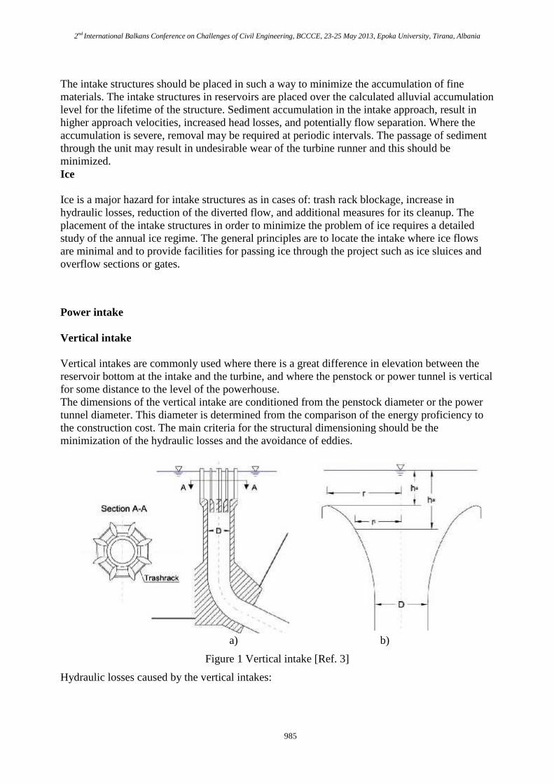
High head intakes H>15m.
These structures are usually placed in reservoirs or in the body of arch, gravity, earth dams. Inthis case the intake structure is placed directly in the resirvoir, and water is conveyed throughdiversion systems to the forebay from where it passes through the intake to the penstock orpressure tunnel.In high head intakes, the hydraulic losses are relatively small compared to the head and the costsfor increasing the dimensions of the intake to decrease the velocity are not neccesary.
Figure 2 Horizontal intakes [Ref. ICE designe]
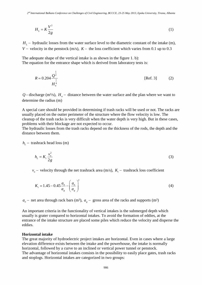
Low head intakes H<15m.
These structures are usually placed in rivers, where the intake is integrated in the body of thedam together with the turbines.
Figure 3 Low head horizontal intake [Ref. 1]
In low head intakes, the hydraulic losses have a great impact on energy production. In thesestructures, an increase in dimensions in order to decrease the velocity is required.
Components of horizontal intakes
Trashrack location and designDepending on the working process of the trashrack they will have an automatic cleanup deviceor will be cleaned manually. The cleanup method depends on the amount of waste expected toaccumulate. For an easy cleanup the trashracks are placed with an inclination 1H:4V. In highhead intakes the trashracks are installed just before the entrance. It is recommended that the flow
2nd International Balkans Conference on Challenges of Civil Engineering, BCCCE, 23-25 May 2013, Epoka University, Tirana, Albania
988
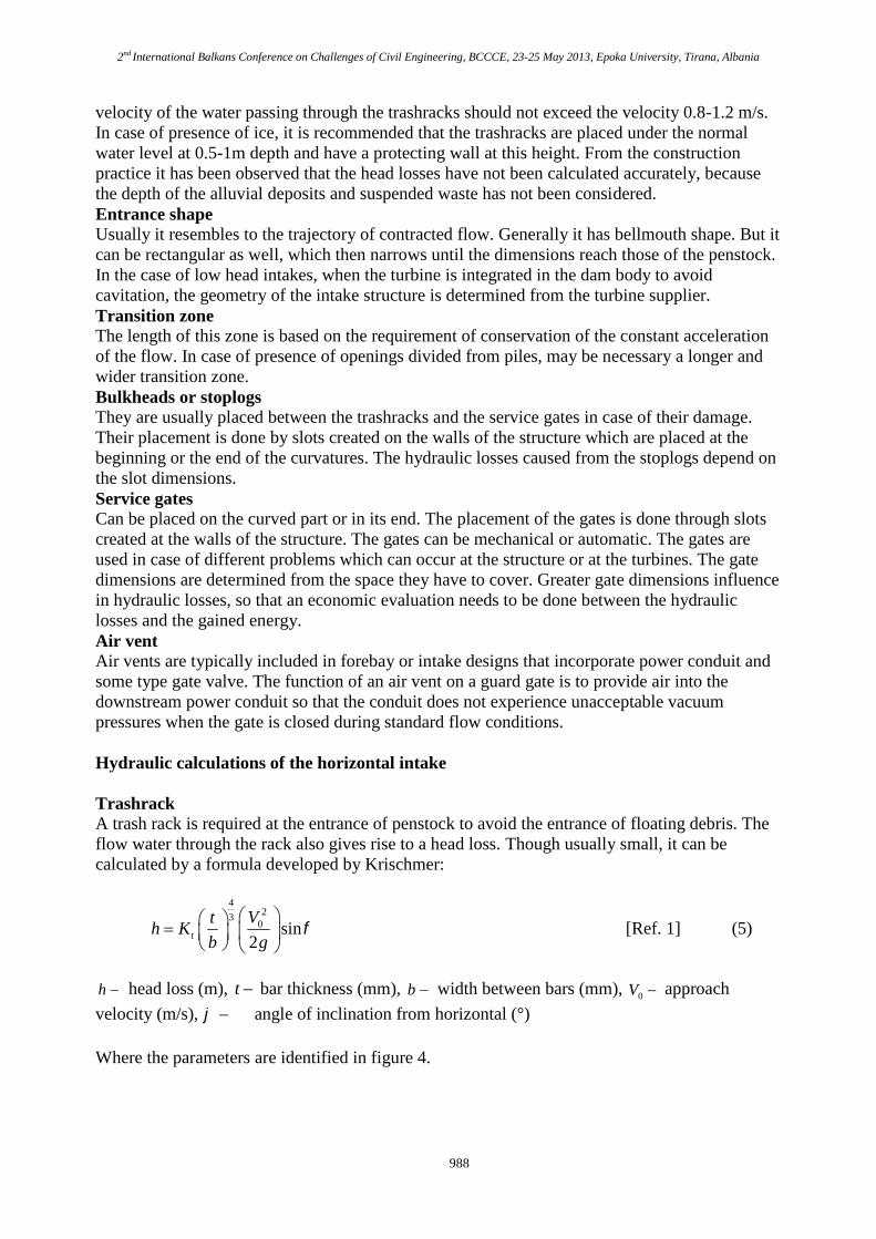
velocity of the water passing through the trashracks should not exceed the velocity 0.8-1.2 m/s.In case of presence of ice, it is recommended that the trashracks are placed under the normalwater level at 0.5-1m depth and have a protecting wall at this height. From the constructionpractice it has been observed that the head losses have not been calculated accurately, becausethe depth of the alluvial deposits and suspended waste has not been considered.Entrance shapeUsually it resembles to the trajectory of contracted flow. Generally it has bellmouth shape. But itcan be rectangular as well, which then narrows until the dimensions reach those of the penstock.In the case of low head intakes, when the turbine is integrated in the dam body to avoidcavitation, the geometry of the intake structure is determined from the turbine supplier.Transition zoneThe length of this zone is based on the requirement of conservation of the constant accelerationof the flow. In case of presence of openings divided from piles, may be necessary a longer andwider transition zone.Bulkheads or stoplogsThey are usually placed between the trashracks and the service gates in case of their damage.Their placement is done by slots created on the walls of the structure which are placed at thebeginning or the end of the curvatures. The hydraulic losses caused from the stoplogs depend onthe slot dimensions.Service gatesCan be placed on the curved part or in its end. The placement of the gates is done through slotscreated at the walls of the structure. The gates can be mechanical or automatic. The gates areused in case of different problems which can occur at the structure or at the turbines. The gatedimensions are determined from the space they have to cover. Greater gate dimensions influencein hydraulic losses, so that an economic evaluation needs to be done between the hydrauliclosses and the gained energy.Air ventAir vents are typically included in forebay or intake designs that incorporate power conduit andsome type gate valve. The function of an air vent on a guard gate is to provide air into thedownstream power conduit so that the conduit does not experience unacceptable vacuumpressures when the gate is closed during standard flow conditions.
Hydraulic calculations of the horizontal intake
TrashrackA trash rack is required at the entrance of penstock to avoid the entrance of floating debris. Theflow water through the rack also gives rise to a head loss. Though usually small, it can becalculated by a formula developed by Krischmer:
423
0 sin2t
Vth K
b g
[Ref. 1] (5)
h head loss (m), t bar thickness (mm), b width between bars (mm), 0V approach
velocity (m/s), angle of inclination from horizontal (°)
Where the parameters are identified in figure 4.
2nd International Balkans Conference on Challenges of Civil Engineering, BCCCE, 23-25 May 2013, Epoka University, Tirana, Albania
989
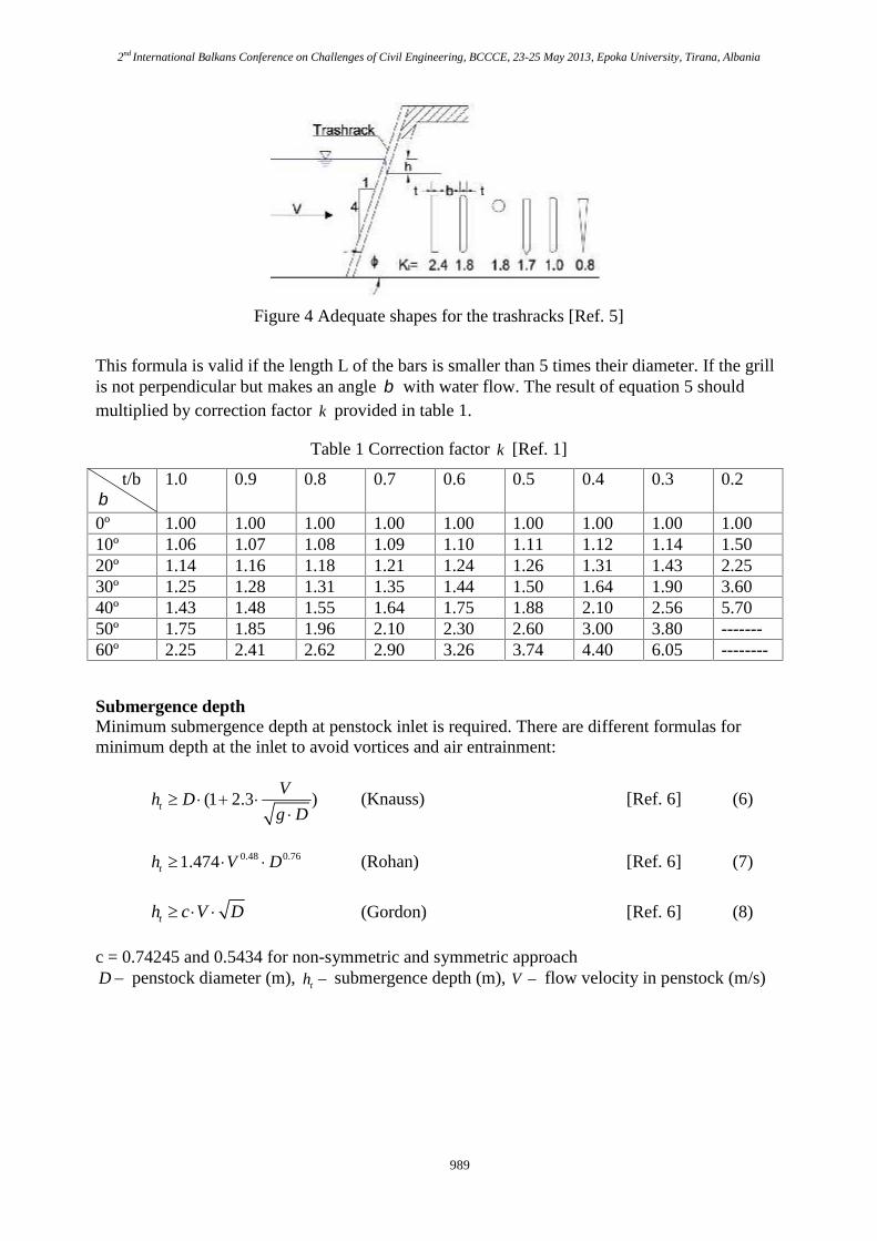
Figure 4 Adequate shapes for the trashracks [Ref. 5]
This formula is valid if the length L of the bars is smaller than 5 times their diameter. If the grillis not perpendicular but makes an angle with water flow. The result of equation 5 shouldmultiplied by correction factor k provided in table 1.
Submergence depthMinimum submergence depth at penstock inlet is required. There are different formulas forminimum depth at the inlet to avoid vortices and air entrainment:
(1 2.3 )t
Vh D
g D
(Knauss) [Ref. 6] (6)
0.48 0.761.474th V D (Rohan) [Ref. 6] (7)
th c V D (Gordon) [Ref. 6] (8)
c = 0.74245 and 0.5434 for non-symmetric and symmetric approachD penstock diameter (m), th submergence depth (m), V flow velocity in penstock (m/s)
2nd International Balkans Conference on Challenges of Civil Engineering, BCCCE, 23-25 May 2013, Epoka University, Tirana, Albania
990
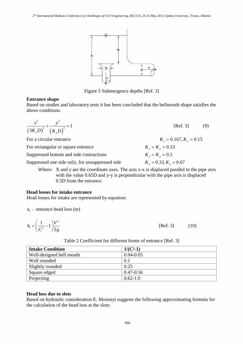
Figure 5 Submergence depths [Ref. 3]
Entrance shapeBased on studies and laboratory tests it has been concluded that the bellmouth shape satisfies theabove conditions.
2 2
2 2 13 x y
x y
K D K D [Ref. 3] (9)
For a circular entrance 0.167, 0.15x yK K
For rectangular or square entrance 0.33x yK K
Suppressed bottom and side contractions 0.5x yK K
Suppressed one side only, for unsuppressed side 0.33, 0.67x yK K Where: X and y are the coordinate axes. The axis x-x is displaced parallel to the pipe axis
with the value 0.65D and y-y is perpendicular with the pipe axis is displaced0.5D from the entrance.
Head losses for intake entranceHead losses for intake are represented by equation:
lh entrance head loss (m)
2
2
11
2l
Vh
C g
[Ref. 3] (10)
Table 2 Coefficient for different forms of entrance [Ref. 3]
Head loss due to slotsBased on hydraulic consideration E. Mosonyi suggests the following approximating formula forthe calculation of the head loss at the slots:
2nd International Balkans Conference on Challenges of Civil Engineering, BCCCE, 23-25 May 2013, Epoka University, Tirana, Albania
991
sh head loss due to slots (m)
22
2 11.2 1
2s
vh
g
[Ref. 1] (11)
cross-section coefficient
2 *
Bh
Bh y h yB
(12)
Weisbach coefficient
30.63 0.37 (13)
v velocity in the entrance flume, just before the slots (m/s), B width of entrance flume(m), h depth of entrance flume (m), e width of slot (m), d depth of slot (m), If
0.2d e then * 0.2y e , If 0.2d e then *y d
The disturbing effect of the opening necessary for the hoisting of the gate is accounted for bydimension
0.2y e (14)
Representing the widening yB of the cross-section.
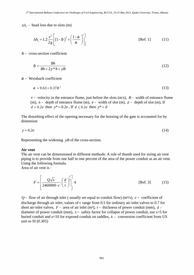
Air ventThe air vent can be dimensioned in different methods: A rule of thumb used for sizing air ventpiping is to provide from one half to one percent of the area of the power conduit as an air vent.Using the following formula.Area of air vent is :
3
2
2460000
Q s dF k
c t
[Ref. 3] (15)
Q flow of air through inlet ( usually set equal to conduit flow) (m³/s), c coefficient ofdischarge through air inlet, values of c range from 0.5 for ordinary air-inlet valves to 0.7 forshort air-inlet valves, F area of air inlet (m²), t thickness of power conduit (mm), d diameter of power conduit (mm), s safety factor for collapse of power conduit, use s=5 forburied conduit and s=10 for exposed conduit on saddles, k conversion coefficient from USunit to SI (0.305)
2nd International Balkans Conference on Challenges of Civil Engineering, BCCCE, 23-25 May 2013, Epoka University, Tirana, Albania
992
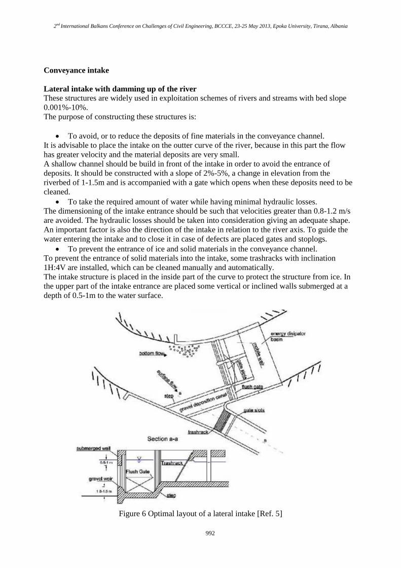
Conveyance intake
Lateral intake with damming up of the riverThese structures are widely used in exploitation schemes of rivers and streams with bed slope0.001%-10%.The purpose of constructing these structures is:
To avoid, or to reduce the deposits of fine materials in the conveyance channel.It is advisable to place the intake on the outter curve of the river, because in this part the flowhas greater velocity and the material deposits are very small.A shallow channel should be build in front of the intake in order to avoid the entrance ofdeposits. It should be constructed with a slope of 2%-5%, a change in elevation from theriverbed of 1-1.5m and is accompanied with a gate which opens when these deposits need to becleaned. To take the required amount of water while having minimal hydraulic losses.
The dimensioning of the intake entrance should be such that velocities greater than 0.8-1.2 m/sare avoided. The hydraulic losses should be taken into consideration giving an adequate shape.An important factor is also the direction of the intake in relation to the river axis. To guide thewater entering the intake and to close it in case of defects are placed gates and stoplogs. To prevent the entrance of ice and solid materials in the conveyance channel.
To prevent the entrance of solid materials into the intake, some trashracks with inclination1H:4V are installed, which can be cleaned manually and automatically.The intake structure is placed in the inside part of the curve to protect the structure from ice. Inthe upper part of the intake entrance are placed some vertical or inclined walls submerged at adepth of 0.5-1m to the water surface.
Figure 6 Optimal layout of a lateral intake [Ref. 5]
2nd International Balkans Conference on Challenges of Civil Engineering, BCCCE, 23-25 May 2013, Epoka University, Tirana, Albania
993
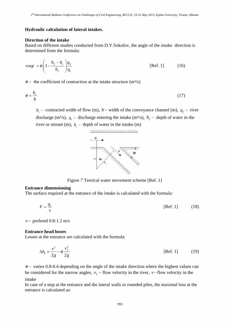
Hydraulic calculation of lateral intakes.
Direction of the intakeBased on different studies conducted from D.Y.Sokolov, the angle of the intake direction isdetermined from the formula:
cos 1 f c f
f c
h h q
h q
[Ref. 1] (16)
the coefficient of contraction at the intake structure (m³/s)
cb
b (17)
cb contracted width of flow (m), b width of the conveyance channel (m), fq river
discharge (m³/s), cq discharge entering the intake (m³/s), fh depth of water in the
river or stream (m), ch depth of water in the intake (m)
Figure 7 Teorical water movement scheme [Ref. 1]
Entrance dimensioningThe surface required at the entrance of the intake is calculated with the formula:
cqF
v [Ref. 1] (18)
v prefered 0.8-1.2 m/s
Entrance head lossesLosses at the entrance are calculated with the formula:
22
2 2f
e
vvh
g g [Ref. 1] (19)
varies 0.8-0.4 depending on the angle of the intake direction where the highest values canbe considered for the narrow angles, fv flow velocity in the river, v flow velocity in the
intakeIn case of a step at the entrance and the lateral walls or rounded piles, the maximal loss at theentrance is calculated as:
2nd International Balkans Conference on Challenges of Civil Engineering, BCCCE, 23-25 May 2013, Epoka University, Tirana, Albania
994
22
1.32 2
fe
vvh
g g [Ref. 1] (20)
Hydraulic losses as a result of trashracks, gate slots are treated at the pressure intakes.
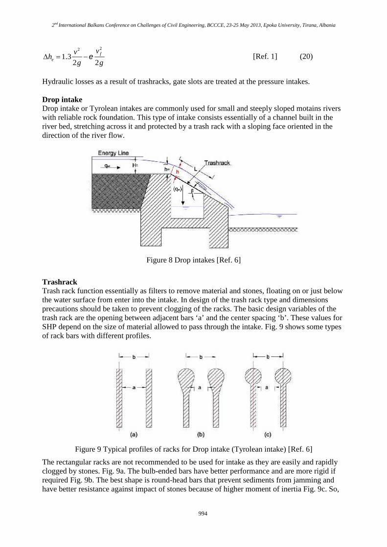
Drop intakeDrop intake or Tyrolean intakes are commonly used for small and steeply sloped motains riverswith reliable rock foundation. This type of intake consists essentially of a channel built in theriver bed, stretching across it and protected by a trash rack with a sloping face oriented in thedirection of the river flow.
Figure 8 Drop intakes [Ref. 6]
TrashrackTrash rack function essentially as filters to remove material and stones, floating on or just belowthe water surface from enter into the intake. In design of the trash rack type and dimensionsprecautions should be taken to prevent clogging of the racks. The basic design variables of thetrash rack are the opening between adjacent bars ‘a’ and the center spacing ‘b’. These values forSHP depend on the size of material allowed to pass through the intake. Fig. 9 shows some typesof rack bars with different profiles.
Figure 9 Typical profiles of racks for Drop intake (Tyrolean intake) [Ref. 6]
The rectangular racks are not recommended to be used for intake as they are easily and rapidlyclogged by stones. Fig. 9a. The bulb-ended bars have better performance and are more rigid ifrequired Fig. 9b. The best shape is round-head bars that prevent sediments from jamming andhave better resistance against impact of stones because of higher moment of inertia Fig. 9c. So,
2nd International Balkans Conference on Challenges of Civil Engineering, BCCCE, 23-25 May 2013, Epoka University, Tirana, Albania
995
this last type of bars should be used systematically for Tyrolean intake. The recommendedopening rack bars for this type is 20 to 40 mm.The racks have to be inspected and cleaned at regular time intervals to prevent potentialobstruction by debris.
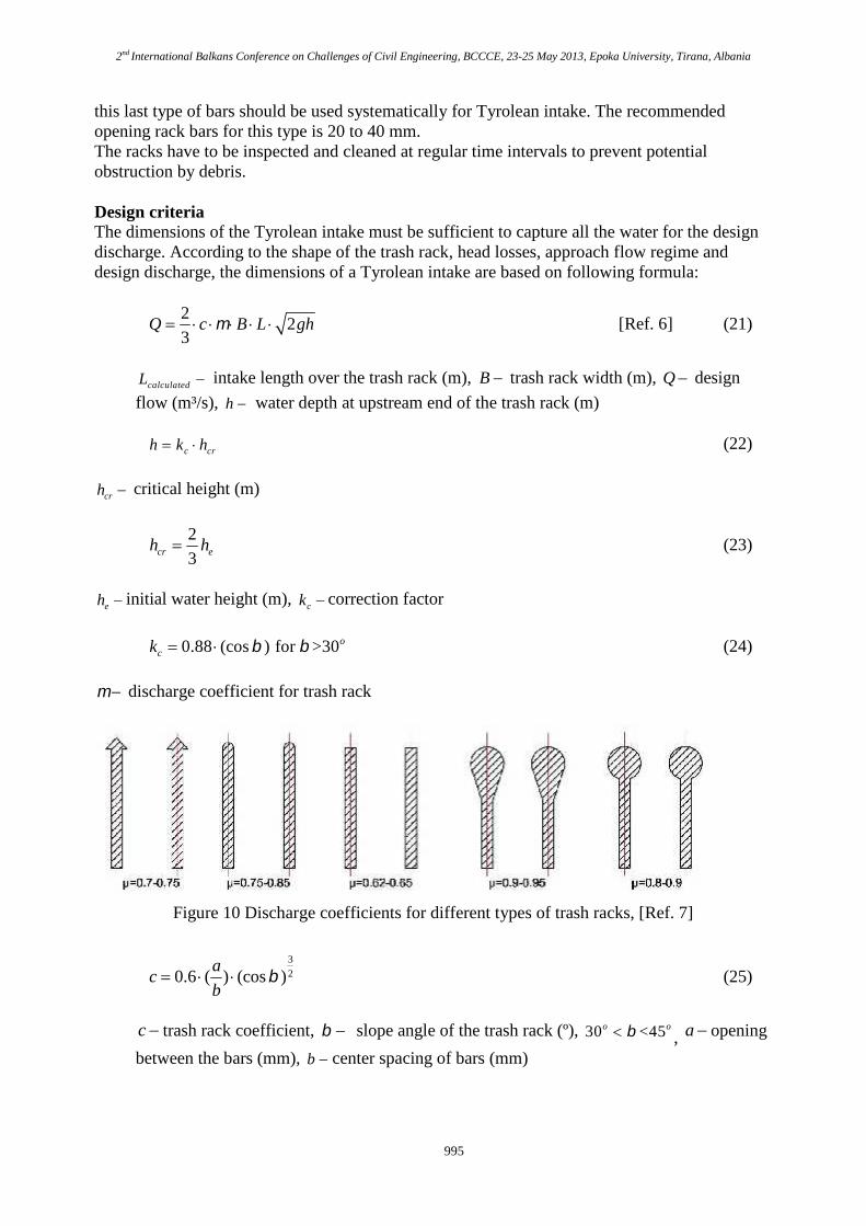
Design criteriaThe dimensions of the Tyrolean intake must be sufficient to capture all the water for the designdischarge. According to the shape of the trash rack, head losses, approach flow regime anddesign discharge, the dimensions of a Tyrolean intake are based on following formula:
22
3Q c B L gh [Ref. 6] (21)
calculatedL intake length over the trash rack (m), B trash rack width (m), Q design
flow (m³/s), h water depth at upstream end of the trash rack (m)
c crh k h (22)
crh critical height (m)
2
3cr eh h (23)
eh initial water height (m), ck correction factor
0.88 (cos ) for >30ock (24)
discharge coefficient for trash rack
Figure 10 Discharge coefficients for different types of trash racks, [Ref. 7]
3
20.6 ( ) (cos )a
cb
(25)
c trash rack coefficient, slope angle of the trash rack (º), 30 <45o o , a opening
between the bars (mm), b center spacing of bars (mm)
2nd International Balkans Conference on Challenges of Civil Engineering, BCCCE, 23-25 May 2013, Epoka University, Tirana, Albania
996
In order to guarantee the diversion of the minimum amount of water when stones becomewedged in the trash rack, or branches and leaves remain on the trash rack at low water levels, thetrash rack should be selected:
1.2 calculatedL L (26)
ConclusionThe most important factors that should be evaluated for the choice of an intake structure are theclimatic, geological, topographic and flow conditions. For the determination of the final designof a hydropower plant, it is very important that all the possible intake structures are analysed andthe most optimal structure is chosen.From the construction practice of intake structures in Albania, it must be emphasized that acertain reserve should be taken into consideration while dimensioning the intake structure. Thisreserve accounts for the depth of the alluvial deposits accumulated at the bottom of the trashrackand the suspended waste on the water surface during the operational phase of the structure.
References
[25] Emil Mosonyi, (1987) Low-Head Power Plant., Akademia Kiado, Budapest.
[26] Emil MosonyI, (1991) High-Head Power Plant, Volume IIA., Akademia Kiado, Budapest.
[27] American Society of Civil Engineers,(1995) Guidelines for Design of Intakes forHydroelectric Plants
[28] American Society of Civil Engineers,(1969) Civil Engineering Guidelines for Planningand Designing Hydro Developments Volume 4 Small Scale Hydro
[29] European Small Hydropower Association 2004, Guide on How to Develop a SmallHydropower Plant
[30] Mohammadreza Andaroodi,(2006) Standardization of Civil Engineering Works of SmallHigh-head Hydropower Plants and Developments of an Optimixation Tool
[31] Helmut Lauterjung & Gangolf Schmidt,(1989) Planning of Water Intake Structures forIrrigation or Hydropower. A Publication of GTZ-Postharvest Project in: DeutscheGesellschaft für Technische Zusammenarbeit (GTZ) GmbH.