International Energy Agency (IEA) Heat Pump Programme – Annex 32 – Workshop in Kyoto, Japan – December 6th, 2007 1 INTEGRATED CO 2 HEAT PUMP SYSTEMS FOR SPACE HEATING AND HOT WATER HEATING IN LOW-ENERGY HOUSES AND PASSIVE HOUSES J. STENE SINTEF Energy Research, Kolbjørn Hejes vei 1D, 7465 Trondheim, Norway, Fax: +47 73593950 [email protected]ABSTRACT Low-energy and passive houses are superinsulated and air-tight buildings where the space heating demand is considerably lower than that of buildings constructed in accordance with common buildings codes. Due to the low space heating demand, the annual heating demand for domestic hot water (DHW) typically consti- tutes 50 to 85% of the total annual heating demand in the residence. A heat pump system can be used to cover the heating demands in low-energy houses and passive houses. The heat pump system can be designed as stand-alone systems, i.e. a heat pump water heater (HPWH) in combination with separate units for space heating, or be an integrated unit for combined space heating and hot water heating (IHPS). Due to compact design, the latter system is most likely to achieve the lowest investment and installation costs and with that the best profitability. Integrated residential heat pump systems using carbon dioxide (CO 2 , R744) as a working fluid can achieve high Coefficient of Performance (COP) due to the unique characteristics of the transcritical cycle with heat rejection in a gas cooler at a gliding CO 2 temperature. Integrated CO 2 heat pumps for space heating and hot water heating can be designed to utilize different heat sources such as bedrock, ground, exhaust ventilation air, ambient air or a combination of exhaust ventilation air and ambient air. Different integrated CO 2 heat pump systems have been investigated, focusing on the design of the gas cooler and the DHW system. It was found that a counter-flow tripartite CO 2 gas cooler in combination with an external single-shell hot water tank and a low-temperature heat distribution system, would enable production of DHW in the required temperature range from 60 to 85ºC and contribute to the highest possible COP for the CO 2 heat pump system. The Seasonal Performance Factor (SPF) for a prototype brine-to-water CO 2 heat pump was calculated on the basis of laboratory measurements and compared with the performance of a high- efficiency HFC brine-to-water heat pump unit. At DHW heating demand ratios above approximately 50%, the CO 2 heat pump system outperformed the HFC heat pump system. Consequently, integrated CO 2 heat pump systems equipped with a tripartite gas cooler represent a very promising, high-efficiency system for combined space heating and DHW heating in low-energy and passive houses. The results presupposes the use of a low-temperature space heating system and optimized design of the DHW tank in order to minimize thermodynamic losses caused by mixing of hot and cold water and conductive heat transfer inside the tank. 1. HEATING DEMANDS IN LOW-ENERGY HOUSES AND PASSIVE HOUSES In low-energy houses and passive houses the space heating demand and the ventilation loss have been greatly reduced compared to houses constructed in accordance with standard building codes. This has been made possible by better insulated and more air-tight building envelopes, advanced ventilation systems with high-efficiency heat recovery and utilization of passive solar heating. Since the DHW demand is more or less the same, the annual heating demand for DHW typically constitutes 50 to 85% of the total annual heating demand in Scandinavian residences – i.e. an annual DHW heating demand ratio of 0.50 to 0.85 (Dokka and Hermstad, 2006). Figure 1.1 shows, as an example, the development of the various heating demands [kWh/(m 2 a)] in single-family houses in Germany (Breembroek, Dieleman, 2001).
Transcript
International Energy Agency (IEA) Heat Pump Programme – Annex 32 – Workshop in Kyoto, Japan – December 6th, 2007 1
INTEGRATED CO2 HEAT PUMP SYSTEMS FOR SPACE HEATING AND HOT WATER HEATING IN
LOW-ENERGY HOUSES AND PASSIVE HOUSES
J. STENE
SINTEF Energy Research, Kolbjørn Hejes vei 1D, 7465 Trondheim, Norway, Fax: +47 73593950
ABSTRACT Low-energy and passive houses are superinsulated and air-tight buildings where the space heating demand is considerably lower than that of buildings constructed in accordance with common buildings codes. Due to the low space heating demand, the annual heating demand for domestic hot water (DHW) typically consti-tutes 50 to 85% of the total annual heating demand in the residence. A heat pump system can be used to cover the heating demands in low-energy houses and passive houses. The heat pump system can be designed as stand-alone systems, i.e. a heat pump water heater (HPWH) in combination with separate units for space heating, or be an integrated unit for combined space heating and hot water heating (IHPS). Due to compact design, the latter system is most likely to achieve the lowest investment and installation costs and with that the best profitability. Integrated residential heat pump systems using carbon dioxide (CO2, R744) as a working fluid can achieve high Coefficient of Performance (COP) due to the unique characteristics of the transcritical cycle with heat rejection in a gas cooler at a gliding CO2 temperature. Integrated CO2 heat pumps for space heating and hot water heating can be designed to utilize different heat sources such as bedrock, ground, exhaust ventilation air, ambient air or a combination of exhaust ventilation air and ambient air. Different integrated CO2 heat pump systems have been investigated, focusing on the design of the gas cooler and the DHW system. It was found that a counter-flow tripartite CO2 gas cooler in combination with an external single-shell hot water tank and a low-temperature heat distribution system, would enable production of DHW in the required temperature range from 60 to 85ºC and contribute to the highest possible COP for the CO2 heat pump system. The Seasonal Performance Factor (SPF) for a prototype brine-to-water CO2 heat pump was calculated on the basis of laboratory measurements and compared with the performance of a high-efficiency HFC brine-to-water heat pump unit. At DHW heating demand ratios above approximately 50%, the CO2 heat pump system outperformed the HFC heat pump system. Consequently, integrated CO2 heat pump systems equipped with a tripartite gas cooler represent a very promising, high-efficiency system for combined space heating and DHW heating in low-energy and passive houses. The results presupposes the use of a low-temperature space heating system and optimized design of the DHW tank in order to minimize thermodynamic losses caused by mixing of hot and cold water and conductive heat transfer inside the tank.
1. HEATING DEMANDS IN LOW-ENERGY HOUSES AND PASSIVE HOUSES In low-energy houses and passive houses the space heating demand and the ventilation loss have been greatly reduced compared to houses constructed in accordance with standard building codes. This has been made possible by better insulated and more air-tight building envelopes, advanced ventilation systems with high-efficiency heat recovery and utilization of passive solar heating. Since the DHW demand is more or less the same, the annual heating demand for DHW typically constitutes 50 to 85% of the total annual heating demand in Scandinavian residences – i.e. an annual DHW heating demand ratio of 0.50 to 0.85 (Dokka and Hermstad, 2006). Figure 1.1 shows, as an example, the development of the various heating demands [kWh/(m2a)] in single-family houses in Germany (Breembroek, Dieleman, 2001).
International Energy Agency (IEA) Heat Pump Programme – Annex 32 – Workshop in Kyoto, Japan – December 6th, 2007 2
Figure 1.1 Development of the annual heating demand [kWh/(m2a)] for German single-family houses
with 150 m2 heated area and 3-4 residents (Breembroek and Dieleman, 2001). Figure 1.2 shows, as an example, the calculated monthly space heating demand [kWh/month] and DHW heating demand for a 100 m2 semi-detached house of different standards in Oslo, Norway. The different standards of the building envelope correspond to a house constructed according the Norwegian building codes of 1997 (BF97), a low-energy house (Energy rating B), a passive house (Energy rating A) and a passive house + (Energy rating A+) (Dokka and Hermstad, 2006). The average monthly DWH heating demand is about 335 kWh/month, which corresponds to an annual DHW heating demand of 4,000 kWh/year. This is the average value for Norwegian residences (Breembroek and Dieleman, 2001). Figure 1.2 Calculated monthly space and DHW heating demand [kWh/month] for a 100 m2 semi-
detached house in Oslo, Norway constructed according to different building standards. The semi-detached house constructed according to BF97 has an annual space heating period of roughly 9 month/year, while the space heating periods for the low-energy house (B), the passive house (A) and the passive house+ (A+) are about 7, 6 and 5 months, respectively. The monthly heating demand for DHW is equal to or higher than the monthly space heating demands during the entire year for the passive houses (A and A+), whereas the monthly space heating demand is higher than the average DHW heating demand during roughly 4 month per year for a low-energy house. Consequently, it is important that integrated heat pump systems for low-energy houses and passive houses are designed for high energy efficiency in DHW heating mode, and that they are able to cover the entire demand without any electric reheating.
International Energy Agency (IEA) Heat Pump Programme – Annex 32 – Workshop in Kyoto, Japan – December 6th, 2007 3
2. INTEGRATED HEAT PUMPS FOR SPACE HEATING AND DHW HEATING A heat pump system can be used to cover the heating demands in low-energy houses and passive houses. The heat pump system can be designed as stand-alone systems, i.e. a heat pump water heater (HPWH) in combination with a separate unit for space heating, or be an integrated unit for combined space heating and hot water heating (IHPS). Due to compact design, the latter system is most likely to achieve the lowest investment and installation costs and with that the best profitability. There exists a large number of different designs for integrated heat pump systems with conventional working fluids, and the main differences are related to the design and operation of the DHW system, including:
• Double-shell tank system – heating of DHW by condenser heat only – the heat pump must have an average supply water temperature above 60ºC in order to cover the entire DHW heating demand – at lower supply temperatures from the heat pump electric reheating of DHW is required – this is not a recommended system design for heat pumps in low-energy houses and passive houses
• Desuperheater system – DHW heating by desuperheat only – the space heating demand is covered by condenser heat, and the compressor is switched on/off according to this demand – the system will only cover the DHW heating demand when there is a space heating demand in the house – this is not a recommended system design for heat pumps low-energy houses and passive houses
• Shuttle-valve system – space heating and DHW heating by condenser heat only – intermittent opera-tion with either space heating or DHW heating – the condensation temperature adjusts to the actual temperature requirement in the space heating and DHW systems – the heat pump is able to cover the entire DHW heating demand if R134a or R290 (propane) is used as a working fluid due to the high maximum condensation temperature – this is a suitable system for low-energy houses and passive houses when the heat pump unit is charged with R134a or R290
• Two-stage DHW system – preheating of DHW with condenser heat and reheating of DHW with desuperheat (one or two storage tanks) – the heat pump may achieve a higher Seasonal Performance Factor than shuttle-valve systems since the utilization of desuperheat for reheating of DHW lowers the average condensation temperature for the heat pump – this is a suitable system for low-energy houses and passive houses. Figure 2.1 shows principle example of a two-stage heat pump DHW system.
• Other combined designs – including utilization of heat from subcooling of the working fluid Figure 2.1 Principle of a residential heat pump system for combined space heating and DHW heating.
DHW is preheated and reheated by means of heat from the condenser and a desuperheater.
International Energy Agency (IEA) Heat Pump Programme – Annex 32 – Workshop in Kyoto, Japan – December 6th, 2007 4
Virtually all residential heat pump systems use HFC as the working fluid, i.e. R404A, R407C, R410A or R134a. Since the HFCs are relatively strong greenhouses gases with GWP values ranging from about 1300 to 2000, they are regulated by the Kyoto Protocol. Although the HFC leakages from residential heat pump units are relatively small, it is regarded a better long-term solution to utilize working fluids that do not have any negative impact on the global environment, such as the non-synthetic (natural) working fluids propane, propylene and carbon dioxide (CO2). CO2 is one of the few non-toxic and non-flammable working fluids that neither contributes to ozone depletion nor global warming, and CO2 therefore represents an interesting long-term alternative to the HFCs. CO2 has excellent thermophysical properties, and by utilizing these properties by means of optimized component and system design for the heat pump unit, the DHW system and the heat distribution system, high energy efficiency can be achieved.
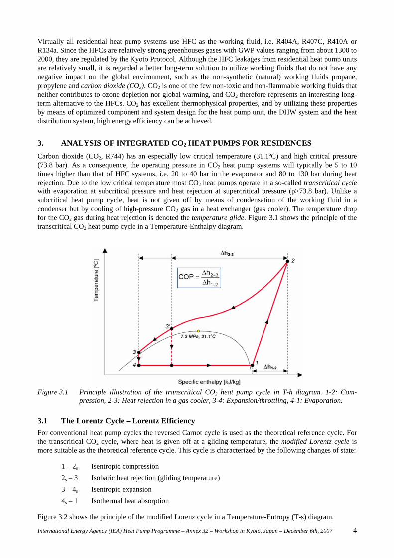
3. ANALYSIS OF INTEGRATED CO2 HEAT PUMPS FOR RESIDENCES Carbon dioxide (CO2, R744) has an especially low critical temperature (31.1ºC) and high critical pressure (73.8 bar). As a consequence, the operating pressure in CO2 heat pump systems will typically be 5 to 10 times higher than that of HFC systems, i.e. 20 to 40 bar in the evaporator and 80 to 130 bar during heat rejection. Due to the low critical temperature most CO2 heat pumps operate in a so-called transcritical cycle with evaporation at subcritical pressure and heat rejection at supercritical pressure (p>73.8 bar). Unlike a subcritical heat pump cycle, heat is not given off by means of condensation of the working fluid in a condenser but by cooling of high-pressure CO2 gas in a heat exchanger (gas cooler). The temperature drop for the CO2 gas during heat rejection is denoted the temperature glide. Figure 3.1 shows the principle of the transcritical CO2 heat pump cycle in a Temperature-Enthalpy diagram.
Figure 3.1 Principle illustration of the transcritical CO2 heat pump cycle in T-h diagram. 1-2: Com-pression, 2-3: Heat rejection in a gas cooler, 3-4: Expansion/throttling, 4-1: Evaporation.
3.1 The Lorentz Cycle – Lorentz Efficiency For conventional heat pump cycles the reversed Carnot cycle is used as the theoretical reference cycle. For the transcritical CO2 cycle, where heat is given off at a gliding temperature, the modified Lorentz cycle is more suitable as the theoretical reference cycle. This cycle is characterized by the following changes of state: 1 – 2s Isentropic compression 2s – 3 Isobaric heat rejection (gliding temperature) 3 – 4s Isentropic expansion 4s – 1 Isothermal heat absorption Figure 3.2 shows the principle of the modified Lorenz cycle in a Temperature-Entropy (T-s) diagram.
International Energy Agency (IEA) Heat Pump Programme – Annex 32 – Workshop in Kyoto, Japan – December 6th, 2007 5
Figure 3.2 Illustration of the modified Lorenz cycle which is used as reference cycle for CO2 heat pumps.
The COP of the modified Lorentz cycle is defined as: (3.1) which gives
(3.2)
where the subscripts 2s and 3 refer to the inlet and outlet temperature of the heated fluid (heat sink), T0 is the temperature of the heat source and Tm is the thermodynamic average temperature during heat rejection. While the Carnot efficiency is used as a measure for the thermodynamic efficiency of a conventional heat pump cycles, the Lorentz efficiency (ηLZ) is used for the transcritical CO2 cycles – defined as: (3.2) where the subscript HP refers to the real CO2 heat pump cycle. Table 3.1 shows, as an example, the measured COP of a residential CO2 heat pump unit for low-temperature space heating and domestic hot water (DHW) heating (COPHP), the Lorentz COP (COPLZ) and the Lorentz efficiency (ηLZ) for the units (Stene, 2004). The COP for the reversed Carnot cycle (COPC) is also shown. Table 3.1 Measured COP (COPHP) and calculated Lorentz COP, Carnot COP and Lorentz efficiency for
residential CO2 heat pumps for floor heating and heating of DHW (Stene, 2004).
Table 3.1 shows that the thermodynamic efficiency for a CO2 heat pump water heater is about 25% higher than that of a CO2 heat pump system for low-temperature space heating due to the better temperature fit between the cooling and heating curves of CO2 and water in the gas cooler. Consequently, integrated CO2 heat pumps are regarded as promising heating systems in low-energy houses and passive houses, since the annual heating demand for DHW typically constitutes 50 to 85% of the total annual heating demand.
LZ
HPLZ COP
COP=η
⎟⎟⎠
⎞⎜⎜⎝
⎛−
=−
=
3
s2
3s2m
0m
mLZ
TTln
TTTandTT
TCOP
( ) ⎟⎟⎠
⎞⎜⎜⎝
⎛⋅−−
−=
3
s203s2
3s2LZ
TTlnTTT
TTCOP
International Energy Agency (IEA) Heat Pump Programme – Annex 32 – Workshop in Kyoto, Japan – December 6th, 2007 6
3.2 Maximum Achievable COP The main factors that determine the Coefficient of Performance (COP) for a single-stage CO2 heat pump are:
• Evaporator – the evaporation temperature (te)
• Compressor – the overall isentropic efficiency (ηis)
• Gas cooler – the mean temperature during heat rejection (tm) o The optimum gas cooler pressure (pgc) o The CO2 outlet temperature (t3)
• Possible recovery of expansion energy o Ejector o Expander
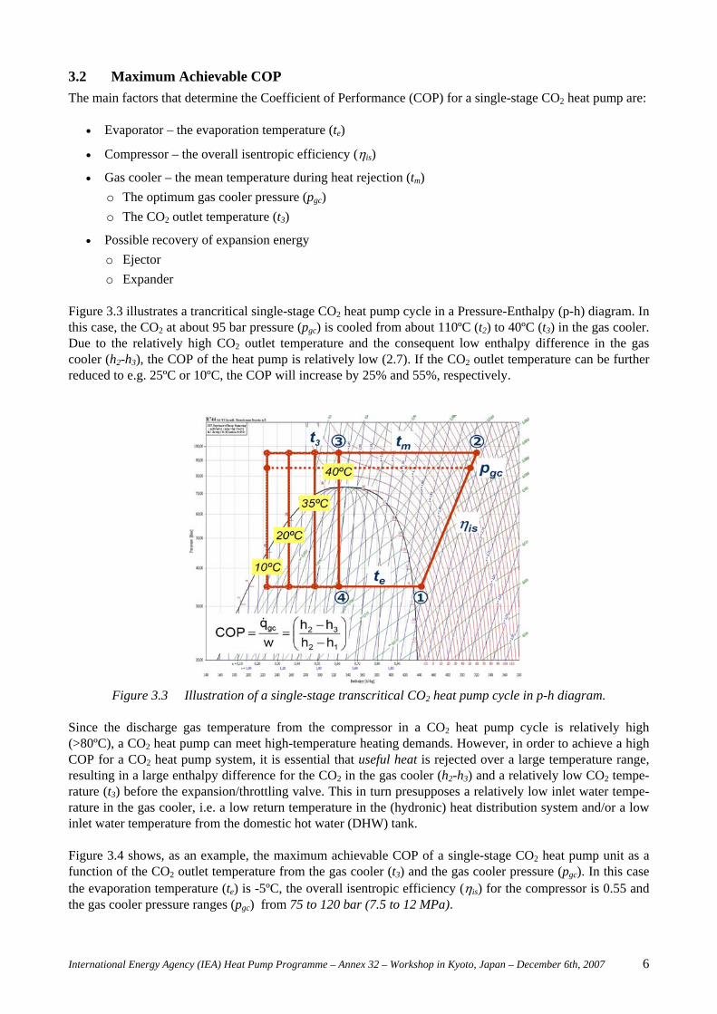
Figure 3.3 illustrates a trancritical single-stage CO2 heat pump cycle in a Pressure-Enthalpy (p-h) diagram. In this case, the CO2 at about 95 bar pressure (pgc) is cooled from about 110ºC (t2) to 40ºC (t3) in the gas cooler. Due to the relatively high CO2 outlet temperature and the consequent low enthalpy difference in the gas cooler (h2-h3), the COP of the heat pump is relatively low (2.7). If the CO2 outlet temperature can be further reduced to e.g. 25ºC or 10ºC, the COP will increase by 25% and 55%, respectively.
Figure 3.3 Illustration of a single-stage transcritical CO2 heat pump cycle in p-h diagram. Since the discharge gas temperature from the compressor in a CO2 heat pump cycle is relatively high (>80ºC), a CO2 heat pump can meet high-temperature heating demands. However, in order to achieve a high COP for a CO2 heat pump system, it is essential that useful heat is rejected over a large temperature range, resulting in a large enthalpy difference for the CO2 in the gas cooler (h2-h3) and a relatively low CO2 tempe-rature (t3) before the expansion/throttling valve. This in turn presupposes a relatively low inlet water tempe-rature in the gas cooler, i.e. a low return temperature in the (hydronic) heat distribution system and/or a low inlet water temperature from the domestic hot water (DHW) tank. Figure 3.4 shows, as an example, the maximum achievable COP of a single-stage CO2 heat pump unit as a function of the CO2 outlet temperature from the gas cooler (t3) and the gas cooler pressure (pgc). In this case the evaporation temperature (te) is -5ºC, the overall isentropic efficiency (ηis) for the compressor is 0.55 and the gas cooler pressure ranges (pgc) from 75 to 120 bar (7.5 to 12 MPa).
International Energy Agency (IEA) Heat Pump Programme – Annex 32 – Workshop in Kyoto, Japan – December 6th, 2007 7
Figure 3.4 The maximum achievable COP for a single-stage CO2 heat pump cycle at -5ºC evaporation
temperature, 55% isentropic compressor efficiency and 75 to 120 gas cooler pressure. It should also be noted that the input power to the compressor is more or less proportional to the gas cooler pressure (pgc), i.e. the higher the gas cooler pressure, the lower the COP. Consequently, CO2 heat pumps should preferably be designed for a moderate optimum gas cooler pressure.
3.3 Optimum Design of the Gas Cooler and the DHW System Integrated (combined) heat pump systems (IHPS) provide both space heating and hot water heating, and the heat is normally rejected to a hydronic heat distribution system. An integrated heat pump system can be designed for high energy efficiency, but in the design process there will always be a trade-off between technical solutions, that reduce the thermodynamic losses in the system, and first costs. The main operating modes of an integrated CO2 heat pump system are: • DHW mode – heating of domestic hot water (DHW) • SH mode – space heating • Combined mode – simultaneous space heating and DHW heating
The CO2 outlet temperature from the gas cooler is determined by: • DHW storage tank and heat distribution system
o The design and temperature characteristics
• Gas cooler unit(s) o The design and heat exchanger configuration
• The compressor discharge temperature (t2) o The evaporation temperature (te) o Possible superheating by a suction gas heat exchanger o The optimum gas cooler (high-side) pressure (pgc)
o The isentropic efficiency of the compressor (ηis)
• Mass flow rates through the counter-flow gas cooler o CO2 (mCO2) o Water (mW)
International Energy Agency (IEA) Heat Pump Programme – Annex 32 – Workshop in Kyoto, Japan – December 6th, 2007 8
The design of an integrated CO2 heat pump system can be classified as follows: External CO2 gas cooler – The gas cooler is connected to a single-shell DHW storage tank by means of a closed water loop. An inverter controlled pump circulates the water from the bottom of the tank through the gas cooler and back to the top of the tank. The heat pump can be equipped with:
• A single gas cooler unit
• A bipartite gas cooler, i.e. two gas cooler units with serial or parallel connection on the CO2 side
• A tripartite gas cooler, i.e. three gas cooler units with serial connection on the CO2 side Integrated CO2 gas cooler and DHW storage tank – The gas cooler can be designed as a tube coil, multi-port extruded (MPE) tube etc., and mounted inside the tank, at the tank surface or in a thermosyphon unit. The heat exchanger for the space heating system can be located:
• Inside the DHW tank
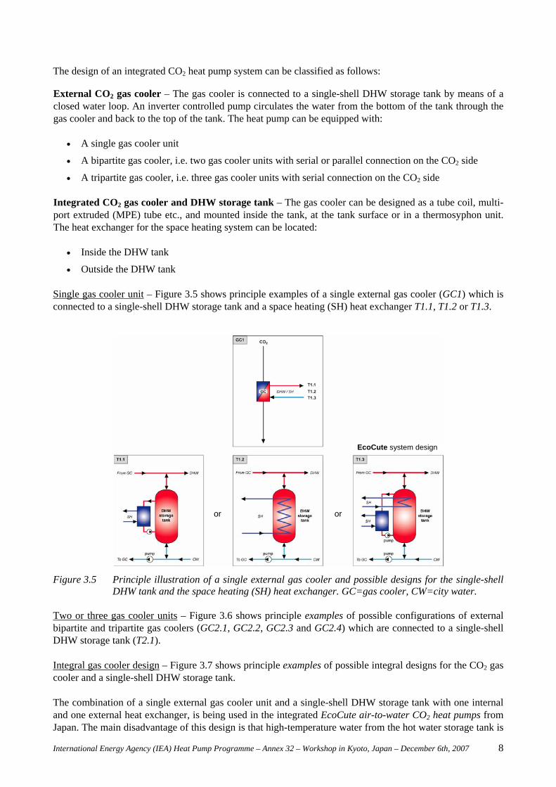
• Outside the DHW tank Single gas cooler unit – Figure 3.5 shows principle examples of a single external gas cooler (GC1) which is connected to a single-shell DHW storage tank and a space heating (SH) heat exchanger T1.1, T1.2 or T1.3.
Figure 3.5 Principle illustration of a single external gas cooler and possible designs for the single-shell
DHW tank and the space heating (SH) heat exchanger. GC=gas cooler, CW=city water. Two or three gas cooler units – Figure 3.6 shows principle examples of possible configurations of external bipartite and tripartite gas coolers (GC2.1, GC2.2, GC2.3 and GC2.4) which are connected to a single-shell DHW storage tank (T2.1). Integral gas cooler design – Figure 3.7 shows principle examples of possible integral designs for the CO2 gas cooler and a single-shell DHW storage tank. The combination of a single external gas cooler unit and a single-shell DHW storage tank with one internal and one external heat exchanger, is being used in the integrated EcoCute air-to-water CO2 heat pumps from Japan. The main disadvantage of this design is that high-temperature water from the hot water storage tank is
or or
EcoCute system design
International Energy Agency (IEA) Heat Pump Programme – Annex 32 – Workshop in Kyoto, Japan – December 6th, 2007 9
being used for space heating. The relatively high return temperature from the space heating heat exchanger will have a major impact on the average inlet water temperature to the CO2 gas cooler. The higher the average inlet water temperature, the lower the COP of the CO2 heat pump unit.
Figure 3.6 Principle examples of possible configurations of bipartite and tripartite gas coolers which are connected to a single-shell DHW storage tank. GC=gas cooler, CW = city water.
Figure 3.7 Principle examples of different design of integral design for the CO2 gas cooler and the single-shell DHW storage tank. INT = integrated, GC= gas cooler, CW = city water.
Table 3.2 presents an overview of the characteristics of the integrated CO2 heat pump systems presented in Figure 3.5 through 3.7. Comprehensive theoretical studies as well as testing of a residential prototype CO2 heat pump system (Stene 2004, 2006) has proved that the CO2 system with a tripartite gas cooler and a single-shell DHW tank (GC2.4 + T2.1) is the most energy efficient design for integrated CO2 heat pumps. This system is presented in detail in the Chapter 3.4.
or or or
Tripartite gas cooler
International Energy Agency (IEA) Heat Pump Programme – Annex 32 – Workshop in Kyoto, Japan – December 6th, 2007 10
Table 3.2 Important characteristics for the gas cooler configurations and DHW storage tank designs
presented in Figure 3.5 through 3.7.
SYSTEM GC1
T1.1 T1.2 T1.3
GC2.1
T2.1
GC2.2
T2.1
GC2.3
T2.1
GC2.4
T2.1
INT
1
INT
2
INT
3
INT
4
INT
5
High-temp. SH 1) Yes Yes No Yes No Yes Yes Yes Yes Yes
1) Capability of providing high-temperature space heating in the Combined mode (tSH>50ºC)
2) Capability of providing high-temperature DHW in the Combined mode (tDHW>60ºC)
3) Technical complexity of the gas cooler units, heat exchangers and DHW storage tank system compared to the baseline CO2 heat pump system: Higher = as baseline system, Lower = simpler than baseline system
4) Requirement of a pump in the DHW circuit – required electric input power to the pump
5) COP in the space heating (SH) mode: Higher = same COP as baseline system, Lower = lower COP than baseline system
6) COP in the domestic hot water (DHW) heating mode: Higher = same COP, Lower = lower COP than the baseline system
7) COP in the Combined heating mode: Higher = same COP, Lower = lower COP than the baseline system
3.4 Evaluation of Integrated CO2 Heat Pump Systems with a Tripartite Gas Cooler A 6.5 kW prototype brine-to-water CO2 heat pump system for combined space heating and hot water heating has been extensively tested and analyzed (Stene, 2004). A number of gas cooler configurations were evaluated, and it was found that a counter-flow tripartite gas cooler for preheating of domestic hot water (DHW), low-temperature space heating and reheating of DHW, would enable production of DHW in the required temperature range from 60 to 85ºC, and contribute to the highest possible COP for the heat pump unit. Figure 3.9 shows the principle of the integrated CO2 heat pump system.
Figure 3.8 The prototype CO2 heat pump unit for space heating and hot water heating (Stene, 2004).
International Energy Agency (IEA) Heat Pump Programme – Annex 32 – Workshop in Kyoto, Japan – December 6th, 2007 11
Figure 3.9 Principle design of the prototype brine-to-water integrated CO2 heat pump system. The prototype CO2 heat pump was equipped with a hermetic rolling piston compressor, a tripartite counter-flow tube-in-tube gas cooler and a counter-flow tube-in-tube suction gas heat exchanger. An expansion valve (back-pressure valve) and a low-pressure liquid receiver (LPR) were used to control the pressure in the tripartite gas cooler. Gas cooler units A and C were connected to an unvented single-shell DHW storage tank and an inverter controlled pump by means of a closed water loop. Gas cooler unit B was connected to a low-temperature hydronic heat distribution system. The integrated CO2 heat pump system was tested in three different operating modes. 1) Simultaneous space heating and DHW heating (Combined mode), 2) Hot water heating (DHW mode) and 3) Space heating (SH mode). During tapping of DHW, hot water was delivered at the tapping site, while cold city water entered the bottom of the DHW tank. During charging of the DHW tank in the Combined and DHW modes, the cold city water from the bottom of the DHW tank was pumped through gas cooler units A and C, heated to the desired temperature level, and returned at the top of the tank. The CO2 system was tested at 40/35ºC, 35/30ºC or 33/28ºC supply/return temperature in the SH system, and 60ºC, 70ºC or 80ºC in the DHW system. The heat rejection process in the three different operating modes is illustrated in temperature-enthalpy diagrams in Figure 3.10 through 3.12. The supply/return temperatures for the floor heating system are 35/30ºC, while the city water temperature and the set-point for the DHW are 6.5 and 70ºC, respectively. In the Combined mode, the so-called DHW heating demand ratio is about 45%, which means that 45% of the total heating capacity of the tripartite gas cooler is used for hot water heating.
Figure 3.10 The heat rejection process for an integrated CO2 heat pump in space heating (SH) mode (35/30ºC) illustrated in a temperature-enthalpy diagram. 85 bar optimum gas cooler pressure.
International Energy Agency (IEA) Heat Pump Programme – Annex 32 – Workshop in Kyoto, Japan – December 6th, 2007 12
Figure 3.11 The heat rejection process for an integrated CO2 heat pump in domestic hot water mode (70ºC) illustrated in a temperature-enthalpy diagram. 100 bar optimum gas cooler pressure.
Figure 3.12 The heat rejection process for an integrated CO2 heat pump in Combined mode (35/30ºC,
70ºC) illustrated in a temperature-enthalpy diagram.85 bar optimum gas cooler pressure. Figure 3.13 shows, as an example, the measured Coefficient of Performance (COP) at optimum gas cooler pressure, 60ºC DHW temperature and various supply/return temperatures for the space heating system. The numbers at the bottom of the Combined mode bars display the DHW heating demand ratio (49-57-69%).
Figure 3.13 The measured maximum COP at 60ºC DHW temperature and various supply/return tempera-tures for the space heating (SH) system for the prototype CO2 heat pump unit (Stene, 2004).
The COP in the Combined mode was about 2 to 10% higher than in the DHW mode due to the moderate optimum gas cooler pressure (85-95 bar) and the relatively low CO2 outlet temperature from the tripartite gas cooler (t3) caused by the excellent temperature fit between the supercritical CO2 and the water.
International Energy Agency (IEA) Heat Pump Programme – Annex 32 – Workshop in Kyoto, Japan – December 6th, 2007 13
The COP in the SH mode was roughly 20 to 30% lower than that of the Combined mode. This was a result of the bad temperature fit between the CO2 and the water, and the fact that the CO2 outlet temperature from the gas cooler (t3) was limited by the relatively high return temperature in the space heating system. The seasonal performance factor (SPF) for the prototype CO2 heat pump and a high-efficiency residential brine-to-water HFC heat pump has been estimated, assuming constant inlet brine temperature for the evapo-rator (0ºC) and constant temperature levels in the space heating system (35/30ºC) and the DHW system (10/60ºC). An improved CO2 heat pump system with 10% higher COP than the prototype system was also investigated in order to demonstrate the future potential of the CO2 system. Higher COP can be achieved by using a more energy efficient compressor, optimizing the tripartite gas cooler or replacing the throttling valve by an ejector. The latter is capable of increasing the COP by typically 10 to 20% (Stene, 2004). For the CO2 heat pump systems, the thermodynamic losses in the DHW tank due to mixing and internal conductive heat transfer were not included when calculating the SPF. The HFC system used a shuttle valve for prioritized DHW heating. Table 3.3 shows the COPs for the heat pump systems at the selected operating conditions.
Table 3.3 The COPs for the brine-to-water CO2 and HFC heat pump systems.
Prototype CO2 heat pump • COP = 3.0 – SH mode at 35/30ºC • COP = 3.8 – DHW mode at 10/60ºC – no electric reheating • COP = 3.9 – Combined mode at 35/30ºC and 10/60ºC
Improved CO2 heat pump • COP = 3.3 – SH mode at 35/30ºC • COP = 4.2 – DHW mode at 10/60ºC – no electric reheating • COP = 4.3 – Combined mode at 35/30ºC and 10/60ºC
HFC heat pump • COP = 4.8 – SH mode at 35/30ºC • COP = 3.0 – DHW mode at 10/60ºC – no electric reheating
Table 3.3 demonstrates that integrated CO2 heat pumps and conventional heat pumps have reversed COP characteristics, i.e. the CO2 units achieve the highest COP during operation in the DHW mode and the Combined mode, whereas the conventional units achieve the highest COP in the SH mode. In Figure 3.14 the calculated SPFs for the three residential heat pump systems during monovalent operation are presented as a function of the seasonal DHW heating demand ratio.
Figure 3.14 The calculated SPF during monovalent operation for a high-efficiency HFC heat pump, the
prototype CO2 heat pump and the improved CO2 heat pump.
3,0
3,5
4,0
4,5
5,0
0 10 20 30 40 50 60 70 80 90 100
DHW Heating Demand Ratio [%]
Sea
sona
l Per
form
ance
Fac
tor
[-]
HFC - High-eff iciency
CO2 - Prototype
CO2 - Improved
3,0
3,5
4,0
4,5
5,0
0 10 20 30 40 50 60 70 80 90 100
DHW Heating Demand Ratio [%]
Sea
sona
l Per
form
ance
Fac
tor
[-]
HFC - High-eff iciency
CO2 - Prototype
CO2 - Improved
International Energy Agency (IEA) Heat Pump Programme – Annex 32 – Workshop in Kyoto, Japan – December 6th, 2007 14
At a low DHW heating demand ratio, the HFC heat pump system was more efficient than the CO2 systems due to their poor COP during operation in the SH mode. At an increasing DHW heating demand ratio, the SPF of the CO2 systems were gradually improved, since an increasing part of the heating demand was covered by operation in the Combined mode and the DHW mode. On the other hand, the SPF for the HFC heat pump system dropped quite rapidly with increasing DHW heating demand, since the COP during operation in the DHW mode was about 38% lower than that of the SH mode. At the actual operating conditions, the break-even for the prototype CO2 system occurred at a DHW heating demand ratio around 60%, whereas the break-even for the improved CO2 system was about 10 percentage points lower. In existing houses where the DHW heating demand ratio typically ranges from 10 to 30%, a high-efficiency HFC heat pump system will be more energy efficient than an integrated singe-stage CO2 heat pump system. However, in low-energy houses and passive houses, where the DHW heating demand ratio typically ranges from 50 to 80%, an integrated CO2 heat pump system will outperform the most energy efficient HFC heat pump system on the market.
4. CONCLUSION Integrated residential heat pump systems using carbon dioxide (CO2, R744) as a working fluid can achieve high Coefficient of Performance (COP) due to the unique characteristics of the transcritical cycle with heat rejection in a gas cooler at a gliding CO2 temperature. Integrated CO2 heat pumps for space heating and hot water heating can be designed to utilize different heat sources such as bedrock, ground, exhaust ventilation air, ambient air or a combination of exhaust ventilation air and ambient air. Different integrated CO2 heat pump systems have been investigated, focusing on the design of the gas cooler and the DHW system. It was found that a counter-flow tripartite CO2 gas cooler in combination with an external single-shell hot water tank and a low-temperature heat distribution system, would enable production of DHW in the required temperature range from 60 to 85ºC and contribute to the highest possible COP for the CO2 heat pump system. The Seasonal Performance Factor (SPF) for a prototype brine-to-water CO2 heat pump was calculated on the basis of laboratory measurements and compared with the performance of a high-efficiency HFC brine-to-water heat pump unit. At DHW heating demand ratios above approximately 50%, the CO2 heat pump system outperformed the HFC heat pump system. Consequently, integrated CO2 heat pump systems equipped with a tripartite gas cooler represent a very promising, high-efficiency system for combined space heating and DHW heating in low-energy and passive houses. The results presupposes the use of a space heating system with a low return temperature as well as optimized design of the DHW tank in order to minimize thermodynamic losses caused by mixing of hot and cold water and conductive heat transfer inside the tank. The tripartite gas cooler design is more complex than traditional gas cooler concepts, and a compact, low-cost tripartite water/CO2 heat exchanger with high performance need to be developed.
5. REFERENCES
Breembroek, G., Dieleman, M., 2001: Domestic Heating and Cooling Distribution and Ventilation Systems and their Use with Residential Heat Pumps. IEA Heat Pump Centre Analysis Report HPC-AR8. ISBN 90-72741-40-8.
Dokka, T.H., Hermstad, K., 2006: Energieffektive boliger for framtiden – en håndbok for planlegging av passivhus og lavenergihus (Energy Efficient Houses for the Future – A Handbook for Planning of Passive Houses and Low-Energy Houses). Norwegian final report from ECBCS Annex 38, Sustainable Solar Housing. SINTEF Building and Infrastructure.
Stene, J., 2004: Residential CO2 Heat Pump System for Combined Space Heating and Hot Water Heating. Doctoral Thesis at the Norwegian University of Technology and Science, Dept. of Energy and Process Engineering, 2004:53. ISBN 82-471-6316-0.
Stene, J., 2006: Residential CO2 Heat Pumps for Combined Space Heating and Hot Water Heating – System Design, Test Procedures and Calculation of SPF. Report no. TR A6102. SINTEF Energy Research, Norway.