50
AIA Pittsburgh A217 Integrated Wall Retrofit Solutions for Existing Masonry Construction for Commercial Buildings Wall_BP16 Amy Wylie & Andre Desjarlais 4-21-2016
| Date post: | 22-Jan-2018 |
| Category: |
Design |
| Upload: | aia-pittsburgh |
| View: | 976 times |
| Download: | 2 times |

AIA PittsburghA217
Integrated Wall Retrofit Solutions
for Existing Masonry Construction
for Commercial BuildingsWall_BP16
Amy Wylie & Andre Desjarlais4-21-2016

Credit(s) earned on completion of
this course will be reported to AIA
CES for AIA members.
Certificates of Completion for both
AIA members and non-AIA
members are available upon
request.
This course is registered with AIA
CES for continuing professional
education. As such, it does not
include content that may be
deemed or construed to be an
approval or endorsement by the
AIA of any material of construction
or any method or manner of
handling, using, distributing, or
dealing in any material or product._______________________________________
____
Questions related to specific materials, methods,
and services will be addressed at the conclusion
of this presentation.

This presentation is protected by US and International Copyright laws.
Reproduction, distribution, display and use of the presentation without written
permission of the speaker is prohibited.
Copyright Materials

Course Description
Join this session to learn about the Integrated Wall Retrofit
Project that aims to identify best-practice recommendations for
an energy-efficient, cost-effective retrofit solution for the interior
of existing masonry walls for commercial buildings in climate
zones 4 & 5, which require insulation on the interior of the
existing façade.
The presenters will review air, thermal, and moisture
performance impacts for a number of integrated retrofit
packages and then discuss the best practice recommendations,
which will be based on evaluation against critical parameters,
simulation results, and laboratory tests, as well as field data
collection.

Learning Objectives
1. Discuss air, thermal and moisture performance impacts for a
number of integrated retrofit packages.
2. Identify best-practice recommendation for an energy efficient, cost-
effective retrofit on the interior of existing masonry wall system.
3. Review and validate the simulation analysis against laboratory test
results performed for thermal performance and air leakage
analysis.
4. Analyze potential energy savings achievable through an integrated
energy efficient retrofit.
At the end of this course, participants will be able to:

Agenda
• Project Background & Description.
• Expert Review & Modeling/Laboratory Results.
• Building Retrofit and Field Data Collection.
• Next Steps.
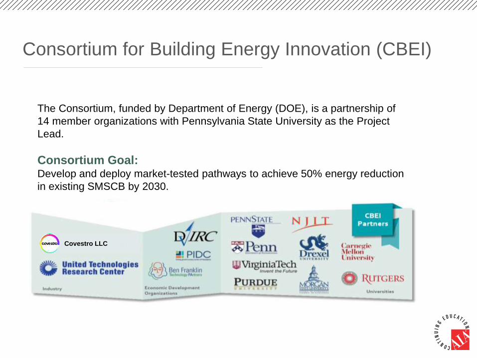
Consortium for Building Energy Innovation (CBEI)
The Consortium, funded by Department of Energy (DOE), is a partnership of
14 member organizations with Pennsylvania State University as the Project
Lead.
Consortium Goal: Develop and deploy market-tested pathways to achieve 50% energy reduction
in existing SMSCB by 2030.
Covestro LLC
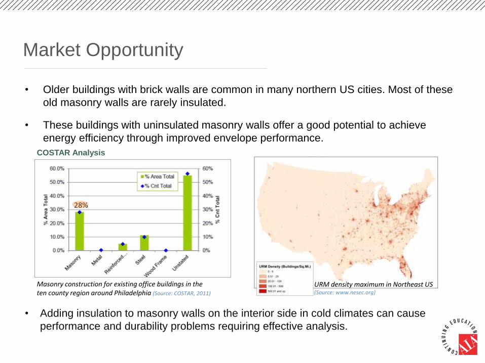
Market Opportunity
• Older buildings with brick walls are common in many northern US cities. Most of these
old masonry walls are rarely insulated.
• These buildings with uninsulated masonry walls offer a good potential to achieve
energy efficiency through improved envelope performance.
28%
URM density maximum in Northeast US (Source: www.nesec.org)
Masonry construction for existing office buildings in the ten county region around Philadelphia (Source: COSTAR, 2011)
• Adding insulation to masonry walls on the interior side in cold climates can cause
performance and durability problems requiring effective analysis.
COSTAR Analysis
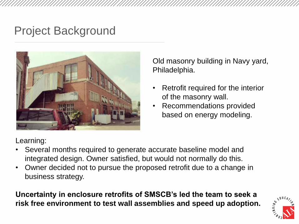
Project Background
Old masonry building in Navy yard,
Philadelphia.
• Retrofit required for the interior
of the masonry wall.
• Recommendations provided
based on energy modeling.
Learning:
• Several months required to generate accurate baseline model and
integrated design. Owner satisfied, but would not normally do this.
• Owner decided not to pursue the proposed retrofit due to a change in
business strategy.
Uncertainty in enclosure retrofits of SMSCB’s led the team to seek a
risk free environment to test wall assemblies and speed up adoption.

Project Objective
Develop a package of wall retrofit solutions that exceeds
ASHRAE 90.1 2010 requirements with a payback of 10-15
years.
Package will be suitable for masonry construction of SMSCB’s and is
presently demonstrated on the 2-story Flexible Research Platform
(FRP) at ORNL.
Target Market:
• Pre-1980s commercial buildings with masonry construction in
climate zones 4 and 5 which require insulation on the interior of the
existing masonry façade.

Project Partners
Market partners:
Technical Advisory Group (TAG):
• Brian Stroik: The Boldt Company.
• Fiona Aldous: Wiss, Janney, Elstner Associates, Inc.
• Pat Conway: International Masonry Institute.

Project Approach
Identified 9 retrofit
scenarios for evaluation
Identified 3 top-
performing scenarios
Identified 2 top-
performing scenarios
To Identify best-
practice scenario
Conducted Industry Expert
Review
(Confirming scenarios to
evaluate)
Evaluated scenarios
against 6 pre-determined evaluation parameters
Constructed mock-ups for 3 top-performing scenarios and evaluated at
ORNL
Demonstrated the 2 top-
performing scenarios on 2-
story FRP
Retrofit scenarios demonstrated on the 2-story Flexible Research
Platform (FRP) at ORNL.
• The 2-story FRP provides opportunity for installing multiple research
cycles so a number of retrofit options can be evaluated.
Current Stage

Initial Proposed Scenarios
Initial 7 retrofit scenarios proposed by the team to be evaluated
Retrofit scenarios were designed to address existing baseline for the FRP.
Baseline Assembly:
• The baseline envelope system for the 2-story
FRP was built to represent the wall systems of
majority of the pre-1980s commercial buildings
in the ten-county region around Philadelphia.
• The data was based on analysis of CBECS and
COSTAR data.

Initial Proposed Scenarios
A. Retain the existing wall (studs+existing insulation+existing drywall)
1. Rigid foam board insulation with taped joints installed over existing insulation
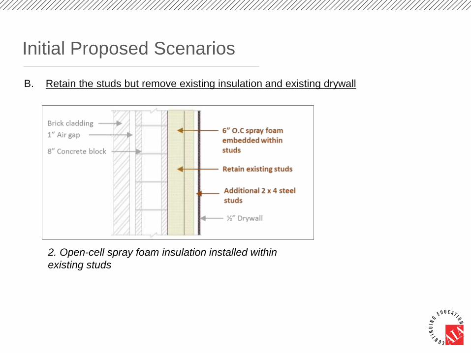
Initial Proposed Scenarios
B. Retain the studs but remove existing insulation and existing drywall
2. Open-cell spray foam insulation installed within
existing studs

Initial Proposed Scenarios
C. Remove existing insulation and steel studs
3. Closed-cell SPF insulation

Initial Proposed Scenarios
C. Remove existing insulation and steel studs
4. Hybrid insulation with 1.5” c.c SPF and
blown-cellulose
5. Hybrid insulation with 2” c.c SPF and
blown-cellulose
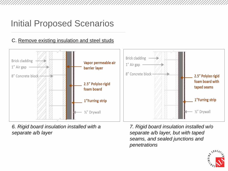
Initial Proposed Scenarios
C. Remove existing insulation and steel studs
6. Rigid board insulation installed with a
separate a/b layer
7. Rigid board insulation installed w/o
separate a/b layer, but with taped
seams, and sealed junctions and
penetrations

Expert Review & Modeling/laboratory Results

Industry Expert Review
Participants:
Occurred August 7th
2014 in Westford, MA
Objectives:
• Get input from industry
experts on proposed
retrofit scenarios and
need for additions.
• Acquire input on
proposed critical
evaluation parameters
and weighted
percentages.
Name Affiliation Building Retrofit Market
Perspective
A. Pat Conway International Masonry Institute Construction Services
Jay H. Crandell Applied Residential Engineering
Services (ARES)
Building Science
Joe Lstiburek Building Science Corporation Building Science
Brian Stroik The Boldt Company Construction Services
B. Valerie Patrick
(Facilitator)
Fulcrum Connection LLC Consortium for Building
Energy Innovation
Tim Wagner United Technologies Research Center Consortium for Building
Energy Innovation
C. Chad Burhman Carlisle Construction Materials Insulation Materials and
Architecture
Laverne Dalgleish Air Barrier Association of America Air Barrier
Andre Desjarlais Oak Ridge National Laboratory Consortium for Building
Energy Innovation
Mike Ducharme Carlisle Construction Materials Roofing System Provider
Jim Lambach Covestro LLC (formerly Bayer
MaterialScience LLC)
Construction Raw Materials
Supplier
Jeff Lear Covestro LLC (formerly Bayer
MaterialScience LLC)
Consortium for Building
Energy Innovation
MacGregor Pierce Hunter Panels LLC Construction Parts Supplier
Amy Wylie Covestro LLC (formerly Bayer
MaterialScience LLC)
Consortium for Building
Energy Innovation
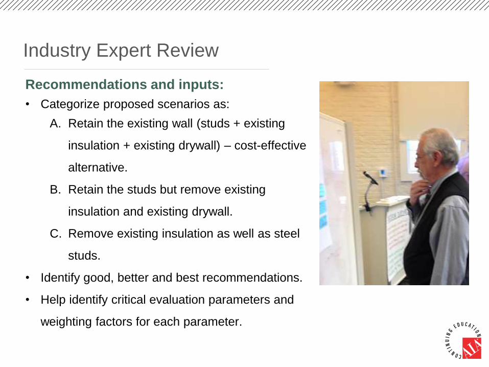
Industry Expert Review
Recommendations and inputs:
• Categorize proposed scenarios as:
A. Retain the existing wall (studs + existing
insulation + existing drywall) – cost-effective
alternative.
B. Retain the studs but remove existing
insulation and existing drywall.
C. Remove existing insulation as well as steel
studs.
• Identify good, better and best recommendations.
• Help identify critical evaluation parameters and
weighting factors for each parameter.
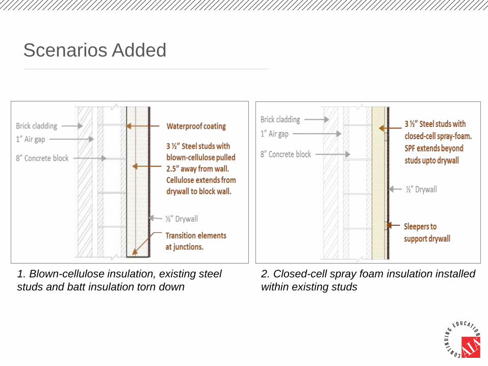
Scenarios Added
1. Blown-cellulose insulation, existing steel
studs and batt insulation torn down
2. Closed-cell spray foam insulation installed
within existing studs
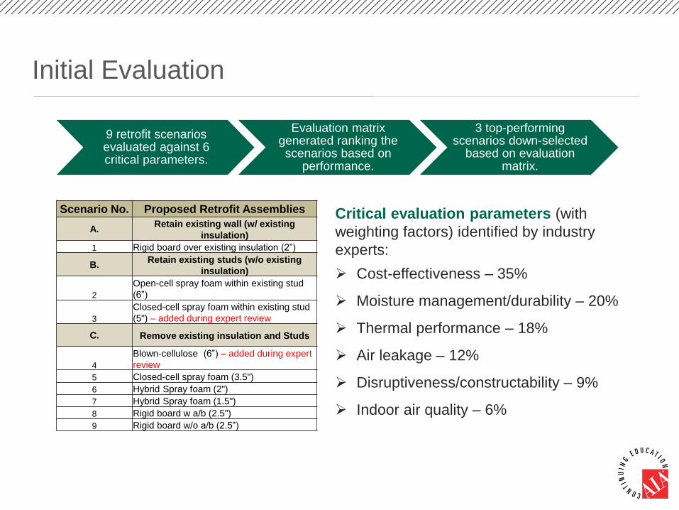
Initial Evaluation
9 retrofit scenarios evaluated against 6 critical parameters.
Evaluation matrix generated ranking the scenarios based on
performance.
3 top-performing scenarios down-selected
based on evaluation matrix.
Scenario No. Proposed Retrofit Assemblies
A.Retain existing wall (w/ existing
insulation)
1 Rigid board over existing insulation (2”)
B.Retain existing studs (w/o existing
insulation)
2
Open-cell spray foam within existing stud
(6”)
3
Closed-cell spray foam within existing stud
(5") – added during expert review
C. Remove existing insulation and Studs
4
Blown-cellulose (6”) – added during expert
review
5 Closed-cell spray foam (3.5")
6 Hybrid Spray foam (2")
7 Hybrid Spray foam (1.5")
8 Rigid board w a/b (2.5")
9 Rigid board w/o a/b (2.5”)
Critical evaluation parameters (with
weighting factors) identified by industry
experts:
Cost-effectiveness – 35%
Moisture management/durability – 20%
Thermal performance – 18%
Air leakage – 12%
Disruptiveness/constructability – 9%
Indoor air quality – 6%
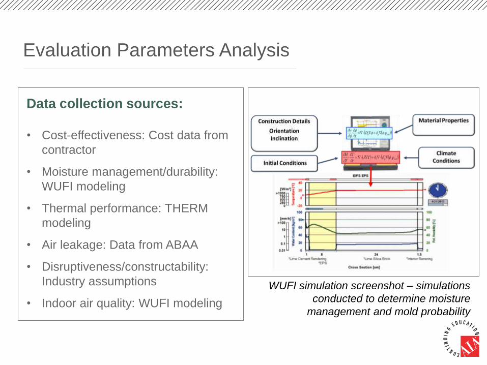
Evaluation Parameters Analysis
Data collection sources:
• Cost-effectiveness: Cost data from
contractor
• Moisture management/durability:
WUFI modeling
• Thermal performance: THERM
modeling
• Air leakage: Data from ABAA
• Disruptiveness/constructability:
Industry assumptions
• Indoor air quality: WUFI modeling
WUFI simulation screenshot – simulations
conducted to determine moisture
management and mold probability

Evaluation Parameters Analysis
• For objective evaluation, all data values under different
evaluation parameters are normalized to range between
0 to 1.
• The normalized data values for each scenario are then
applied with the respective weighted percentages for
each evaluation criteria.
• Final ranking matrix combines the weighted percentages
for all criteria and provides the total weighted percentage
for each scenario.

Evaluation Matrix – Cost-Effectiveness
Cost data for all scenarios provided by Brian Stroik
A. Retain Existing Wall
1
Rigid board over existing
insulation 2" Rigid foam board 4.35 1st
B. Retain Existing Studs
2 Open-cell spray foam 6" o.c spray foam 8.75 5th
3
Closed-cell spray foam
within existing stud (5") 4.5" c.c spray foam 8.65 4th
C. Remove Existing Wall
Completely
4 Blown-cellulose 6.0" 9.75
5 Closed-cell spray foam (3.5") 3.5" 9.40
6 Hybrid Spray foam (2") 2" c.c SPF + 3.5" cellulose 10.10
7 Hybrid Spray foam (1.5") 1.5" c.c SPF + 3.5" cellulose 9.00
8 Rigid board w a/b (2.5") 2.5" 8.05 3rd
9 Rigid board w/o a/b 2.5" 6.55 2nd
No. RankingScenariosInsulation type and
thickness
Cost
($/sq.ft)

Evaluation Matrix – Thermal Performance
Thermal performance for all proposed scenarios analyzed based on THERM software simulation
Assuming existing insulation is in perfect condition
A. Retain Existing Wall
1
Rigid board over existing
insulation * 2" Rigid foam board 25.50 0.039 1st
B. Retain Existing Studs
2 Open-cell spray foam 6" o.c spray foam 19.20 0.052
3
Closed-cell spray foam within
existing stud (5") 4.5" c.c spray foam 15.20 0.066
C. Remove Existing Wall
Completely
4 Blown-cellulose 6.0" 22.10 0.045 3rd
5 Closed-cell spray foam (3.5")3.5" 22.10 0.045 3rd
6 Hybrid Spray foam (2") 2" c.c SPF + 3.5" cellulose 25.00 0.040 2nd
7 Hybrid Spray foam (1.5") 1.5" c.c SPF + 3.5" cellulose 22.00 0.045 4th
8 Rigid board w a/b (2.5") 2.5" 20.80 0.048
9 Rigid board w/o a/b 2.5" 20.80 0.048
No. RankingScenariosInsulation type and
thickness
R-value U-value (1/R)
Thermal Performance

Air Leakage
(l/s.sq.m) @75Pa
A. Retain Existing Wall
1
Rigid board over existing
insulation
2" Rigid foam board with
taped seams 0.039 Good
B. Retain Existing Studs
2 Open-cell spray foam
6" o.c spray foam with taped
drywall 0.038 Good
3
Closed-cell spray foam
within existing stud (5") 4.5" c.c spray foam 0.009 Better
C. Remove Existing Wall
Completely
4 Blown-cellulose
6.0" blown-cellulose with a
separate fluid applied
membrane for air-tightness 0.001 Best
5 Closed-cell spray foam (3.5")3.5" c.cSPF 0.009 Better
6 Hybrid Spray foam (2") 2" c.c SPF + 3.5" cellulose 0.009 Better
7 Hybrid Spray foam (1.5") 1.5" c.c SPF + 3.5" cellulose 0.009 Better
8 Rigid board w a/b (2.5")
2.5" rigid board with
separate fluid applied
membrane for air-tightness 0.001 Best
9 Rigid board w/o a/b
2.5" rigid board with taped
seams 0.039 Good
No. RankingScenarios
Insulation type and
thickness with a/b
material
Air Leakage Rate
Evaluation Matrix – Air Leakage
Air leakage data for proposed scenarios obtained from information on ABAA website for air leakage rate for different buildingassemblies

Evaluation Matrix – Moisture Management
Moisture performance for the proposed scenarios analyzed based on potential for condensation between insulation and concrete block masonry. WUFI simulation utilized to analyze probability of condenstion.
Moisture
Management
A. Retain Existing Wall
1
Rigid board over existing
insulation 2" Rigid foam board No
B. Retain Existing Studs
2 Open-cell spray foam 6" o.c spray foam No
3
Closed-cell spray foam within
existing stud (5") 4.5" c.c spray foam No
C. Remove Existing Wall
Completely
4 Blown-cellulose 6.0" Yes Poor
5 Closed-cell spray foam (3.5") 3.5" No
6 Hybrid Spray foam (2") 2" c.c SPF + 3.5" cellulose No
7 Hybrid Spray foam (1.5") 1.5" c.c SPF + 3.5" cellulose No
8 Rigid board w a/b (2.5") 2.5" No
9 Rigid board w/o a/b 2.5" No
No. RankingScenariosInsulation type and
thickness
Condensation

Evaluation Matrix – Disruptiveness
Space requires
to be vacated
Penalty for
space to be
unoccupied
Interior Space
taken up for
retrofit (in
inches)
A. Retain Existing Wall
1
Rigid board over existing
insulation 2" Rigid foam board Yes 0 Days 7.5 2nd
B. Retain Existing Studs
2 Open-cell spray foam 6" o.c spray foam Yes 1 Day 8.5
3
Closed-cell spray foam
within existing stud (5") 4.5" c.c spray foam Yes 1 Day 5.0 3rdC. Remove Existing Wall
Completely
4 Blown-cellulose 6.0" Yes 1 Day 6.5
5
Closed-cell spray foam
(3.5") 3.5" Yes 1 Day 6.0 4th
6 Hybrid Spray foam (2") 2" c.c SPF + 3.5" cellulose Yes 1 Day 6.5
7 Hybrid Spray foam (1.5") 1.5" c.c SPF + 3.5" cellulose Yes 1 Day 6.0
8 Rigid board w a/b (2.5") 2.5" Yes 0 Days 4.0 1st
9 Rigid board w/o a/b 2.5" Yes 0 Days 4.0 1st
No. RankingScenariosInsulation type and
thickness
Disruptiveness
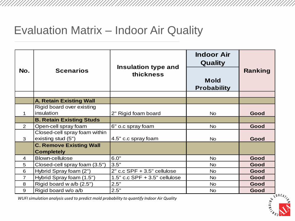
Evaluation Matrix – Indoor Air Quality
WUFI simulation analysis used to predict mold probability to quantify Indoor Air Quality
Indoor Air
Quality
A. Retain Existing Wall
1
Rigid board over existing
insulation 2" Rigid foam board No Good
B. Retain Existing Studs
2 Open-cell spray foam 6" o.c spray foam No Good
3
Closed-cell spray foam within
existing stud (5") 4.5" c.c spray foam No Good
C. Remove Existing Wall
Completely
4 Blown-cellulose 6.0" No Good
5 Closed-cell spray foam (3.5") 3.5" No Good
6 Hybrid Spray foam (2") 2" c.c SPF + 3.5" cellulose No Good
7 Hybrid Spray foam (1.5") 1.5" c.c SPF + 3.5" cellulose No Good
8 Rigid board w a/b (2.5") 2.5" No Good
9 Rigid board w/o a/b 2.5" No Good
No. RankingScenariosInsulation type and
thicknessMold
Probability
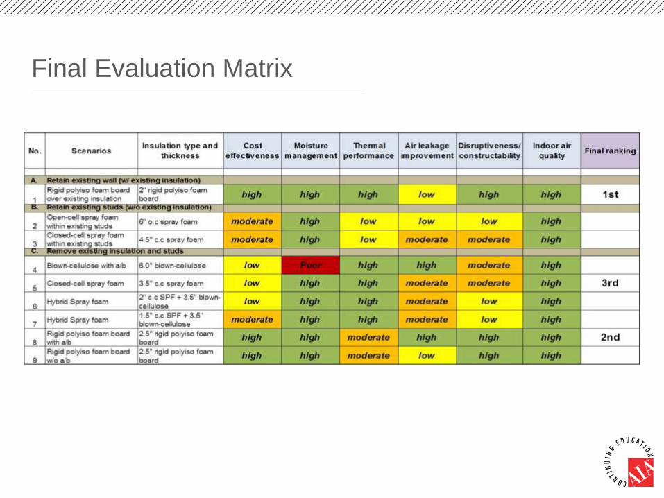
Final Evaluation Matrix

Down-selected Scenarios Based on Evaluation
Matrix
1. Retain existing insulation; install 2” PIR board with taped seams on existing
wall.
2. Demolish existing insulation; install 2.5” PIR board with a separate air barrier
layer on the inner face of the CMU wall.
3. Demolish existing insulation; install 3.5” closed-cell (c.c) SPF with 1.5” c.c
SPF as continuous insulation on the inner face of the CMU wall.
Good solution, but may not be applicable in all situations. Retrofit
dependent on the condition of existing insulation.

Laboratory Evaluation
Mock-up walls constructed for the 3
down-selected scenarios
Conducted laboratory test for thermal
performance and air leakage
Down-selected 2 top-performing scenarios
based on lab test evaluations
ASTM C1363 Hot Box Test Apparatus. ASTM E283/E2357 Air Leakage Test Apparatus.
Thermal performance test in accordance
with ASTM C1363.Air leakage test in accordance with
ASTM E283.

Thermal Performance Test Results
Thermal performance (ASTM C1363) test results
ASHRAE 90.1 2010 requirements (mass walls)
CriteriaClimate Zone 4 max U-value - 0.104
Meets the criteriaClimate Zone 5 max U-value - 0.090
Scenarios
Retain existing insulation + 2” PIR boards
with taped seams.U - 0.048
Demolish existing insulation + 2.5” PIR
board with a separate a/b layer.U – 0.056
Demolish existing insulation + 3.5” c.c
SPF.U – 0.046
1
2
3

Air Leakage Test Results
Air leakage test results (ASTM E283)
Scenario
Air leakage for
building
assembly
ASHRAE
compliance
option
CriteriaBy material
By assembly
Baseline. 2.7 L/ s.m2
Retain existing insulation + 2" PIR board with taped
seams.
1.8 L/s.m2
(0.0005 L/s.m2)by material**
Demolish existing insulation + 2.5" PIR board with a
separate a/b layer.
0.28 L/s.m2***
(0.001 L/s.m2)by material**
Demolish existing insualtion + 3.5" c.c SPF. 0.015 L/s.m2 by assembly*
1
2
3
*ASHRAE 90.1 2010 air barrier installation compliance by assembly requires air leakage < 0.2 L/s.m2.
** ASHRAE 90.1 2010 air barrier installation compliance by material requires material with air permeability < 0.02 L/s.m2.
***Adhesive accompanying the air barrier membrane (to ensure effective adherence) was not used in this scenario in order to facilitate easy
removal of the membrane from the mock-up wall frame for future testing.

Energy Saving and Payback Period
Scenario (R-value of assembly)Baseline 8 L/s.m2 and
existing insulation (R10)
Baseline 8 L/s.m2 and no
existing insulation
Total HVAC
energy savings
Payback
periodCost/sq.ft
Total HVAC
energy
savings
Payback
periodCost/ sq.ft
Retain existing insulation + 2" PIR board
with taped seams (R-20.7).30% 14 yrs $4.35 - - -
Demolish existing insulation + 2.5" PIR
board with a separate a/b layer (R-
17.6).
25% 29 yrs $8.05 31% 17 yrs $6.05
Demolish existing insulation + 3.5" c.c
SPF (R-21.6).36% 25 yrs $9.40 41% 16 yrs $7.40
For baseline with no existing insulation, demolition of existing insulation was not needed, so the cost
of demolition was eliminated from the cost/ft2 for each scenario.
Completed EnergyPlus simulations of the building to determine yearly savings, converted that to
dollars using data from EIA, and computed a simple payback.
1
2
3

Laboratory Tests Performance Summary
MetricASHRAE 90.1 2010 thermal
requirements (mass walls)
ASHRAE 90.1
2010 air leakage
compliance
Payback period
CriteriaClimate Zone 4
max U-value
- 0.104 Meets
criteria
By material
Between 10 - 15 years
Climate Zone 5max U-value
- 0.090By assembly
Scenario Baseline with
no existing
insulation
Baseline with
existing
insulation
Retain existing insulation +
2" PIR board with taped
seams.
U - 0.048 by material N/A 14
Demolish existing insulation
+ 2.5" PIR board with a
separate a/b layer.
U – 0.056 by material 17 29
Demolish existing insulation
+ 3.5" c.c SPF.U – 0.046 by assembly 16 25
Team & TAG Recommendation: Scenario 1 and 3 chosen for
demonstration on Flexible Research Platform at ORNL.
1
2
3

Building Retrofit & Field Data Collection
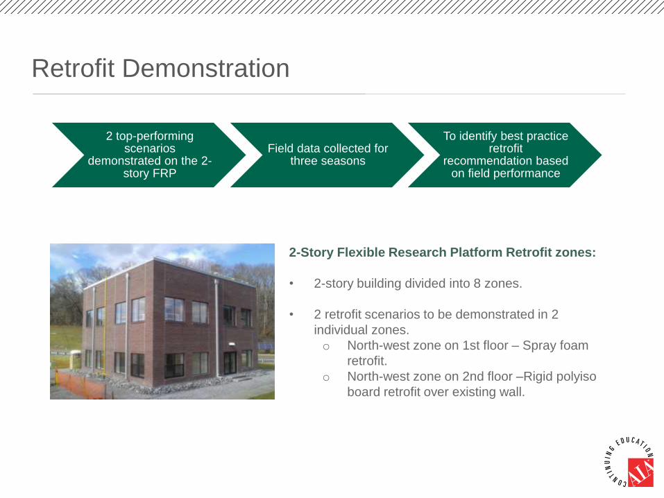
Retrofit Demonstration
2-Story Flexible Research Platform Retrofit zones:
• 2-story building divided into 8 zones.
• 2 retrofit scenarios to be demonstrated in 2
individual zones.
o North-west zone on 1st floor – Spray foam
retrofit.
o North-west zone on 2nd floor –Rigid polyiso
board retrofit over existing wall.
2 top-performing scenarios
demonstrated on the 2-story FRP
Field data collected for three seasons
To identify best practice retrofit
recommendation based on field performance

Constructability Analysis for the Two Demonstrated
Retrofit Scenarios
PIR foam board Closed-cell spray foam
Loss of interior
floorspace
3.5” 1.5”
Installation cost Most cost-effective solution. Installation cost higher than the polyiso board
scenario.
Installation General contractor. Certified spray foam contractor.
Ease of construction Need to maintain effective seal between PIR
board and wall to prevent convective loops.
Spray foam conforms to wall surface due to
spray application.
Seams and junctions Require to be taped and sealed effectively. Applied as monolithic layer effectively sealing
junctions.
Air and moisture
barrier
Achieved by taping boards seams and
sealing junctions.
Spray foam served as air and moisture
barrier.
Inaccessible
areas/junctions
Challenging to maintain air and moisture
seal.
Comparatively easy to spray and seal
inaccessible areas.
Reoccupancy period Permitted after retrofit installation. Permitted 24hrs after retrofit installation.

Field Test Setup
Spray foam retrofit North-west zone – 1st floor: north and west facing walls.
PIR foam board retrofit North-west zone – 2nd floor: north and west facing walls.
RH1: Between
brick and block.
RH2: Between
block and
insulation.
RH3: On
interior wall
surface
Sensor layout within the baseline exterior wall assembly for the two-
story Flexible Research Platform.
Bri
ck
Air
gap
Co
ncr
ete
blo
ck
Insu
lati
on
Dry
wal
l
Retrofit zones:
Sensor location and data collection:
• Data reported at this stage has been collected from west
wall sensors.
• Data analyzed:
- Interior and exterior temperatures.
- Heat flux through the wall assembly.
- Moisture performance for the assembly.
• Data analyzed for a typical week in:
- Sept.: (moderate exterior temperatures).
- Nov.: (slightly lower exterior temperatures).

Initial Field Data Results
Place Holder

Initial Field Data Results
Place Holder
Initial Field Data Results
Place Holder

Next Steps

Next Steps
• Continue collecting field data for the retrofit solutions demonstrated
on the FRP.
• Evaluate field data against initial evaluation results and lab test
results.
• Identify best practice recommendation based on field performance.
• Disseminate best practice recommendations, generated through the
project, to the industry.
• Execute commercialization plan.
Commercialization/ Dissemination Plan
• Utilize regional and annual conferences through industry associations to
disseminate findings to the construction industry.
o CONSTRUCT 2015 – Presented.
o RCI International Convention and Trade Show 2016.
o Air Barrier Association of America (ABAA) Conference and Trade Show
2016 – Will present on March 24th.
• Publish project findings through journal articles/research articles through
various platforms such as:
o Building Research Information Knowledgebase (BRIK).
o Construction Specifier Magazine.
• Potentially organize education webinars through industry association
programs to disseminate project results.

Thank You
The following statements apply to all slides in this presentation:
This presentation may contain forward-looking statements based on current
assumptions and forecasts made by Covestro AG or subgroup management. Various
known and unknown risks, uncertainties and other factors could lead to material
differences between the actual future results, financial situation, development or
performance of the company and the estimates given here. These factors include those
discussed in Covestro’s and Bayer’s public reports which are available on the Covestro
website at www.covestro.com as well as on Bayer AG’s website at www.bayer.com.
Covestro assumes no liability whatsoever to update these forward-looking statements or
to conform them to future events or developments.

This concludes The American Institute of Architects
Continuing Education Systems Course
AIA Pittsburgh
Amy Wylie:
Andre Desjarlais:


