Integration between direct steam generation in linear solar collectors and supercritical carbon dioxide Brayton power cycles L. Coco-Enrı ´ quez * , J. Muñoz-Antón, J.M. Martı ´ nez-Val GIT Universidad Politécnica de Madrid, José Gutiérrez Abascal 2, 28006 Madrid, Spain ARTICLE INFO Article history: Received 22 December 2014 Accepted 2 May 2015 Available online 28 May 2015 Keywords: Direct steam generation Brayton power cycle Supercritical carbon dioxide Parabolic trough Linear Fresnel ABSTRACT Direct Steam Generation in Parabolic Troughs or Linear Fresnel solar collectors is a technology under development since beginning of nineties (1990's) for replacing thermal oils and molten salts as heat transfer fluids in concentrated solar power plants, avoiding environmental impacts. In parallel to the direct steam generation technology development, supercritical Carbon Dioxide Brayton power cycles are maturing as an alternative to traditional Rankine cycles for increasing net plant efficiency and reducing balance of plant equipments dimensions and cots. For gaining synergies between these two innovative technologies, in this paper, Direct Steam Generation and Brayton power cycles are integrated in line focusing solar power plants. Four configurations are studied: Configuration 1 consists on installing a condenser between solar field and power cycle; condensing the heat transfer fluid (steam water) with the balance of plant working fluid (carbon dioxide). The condenser would be a shell & tubes type. Along tubes carbon dioxide flows, and steam water condensates at shell side. Main advantage of the condenser equipment is the high heat transfer coefficient at water condensing side, reducing condenser dimension and weight. The main disadvantage of this configuration is the high operating pressure required in solar field for condensing steam into liquid water. This pressure should be between 150 bar and 175 bar for obtaining 400ºC at turbine inlet. In the Configuration 2, the superheated steam delivered by solar collectors transfers the heat energy in a primary heat exchanger to the balance of plant working fluid. In this configuration the steam not condensate into liquid water, and only reduces the temperature from 550ºC 560ºC to 420ºC. The steam pressure drops in solar field along receivers, headers and heat exchangers are compensated by means of steam compressors. This second solution is compatible with higher turbine inlet temperatures, up to 550º C. The keystones of this second configuration are the steam conditions at compressor inlet, pressure ~175 bars and temperature ~420ºC, for minimizing steam compressor electrical consumption. The third design solution (Configuration 3) includes a solar field with direct steam generation in solar collectors with boiling recirculation mode, but the balance of plant is integrated by two Brayton power cycles in cascade. The first power cycle operating at 550ºC turbine inlet, and the second cycle at 410ºC turbine inlet. Main advantage is the integration between a validated direct steam generation technology (recirculation boiling mode) with the Brayton power cycles avoiding steam compressors, a technology not yet commercially available, and main drawback of this design is the increasing number of balance of plant equipments. The Configuration 4 is very similar to the Configuration 2, with the same direct steam generation solar field with superheated steam without condensing, and a single reheating stage solar field with molten salt as heat transfer fluid. * Corresponding author. Technical University of Madrid. UPM, Spain. Tel.: +34 629 56 17 38. E mail address: [email protected](L. Coco Enrı ´quez).
Transcript
Integration between direct steam generation in linear
solar collectors and supercritical carbon dioxide Brayton power cycles
L Coco-Enrıquez J Muntildeoz-Antoacuten JM Martınez-Val
GIT Universidad Politeacutecnica de Madrid Joseacute Gutieacuterrez Abascal 2 28006 Madrid Spain
ARTICLE INFO
Article history Received 22 December 2014 Accepted 2 May 2015 Available online 28 May 2015
Keywords Direct steam generation Brayton power cycle Supercritical carbon dioxide Parabolic trough Linear Fresnel
ABSTRACT Direct Steam Generation in Parabolic Troughs or Linear Fresnel solar collectors is a technology under development since beginning of nineties (1990s) for replacing thermal oils and molten salts as heat transfer fluids in concentrated solar power plants avoiding environmental impacts In parallel to the direct steam generation technology development supercritical Carbon Dioxide Brayton power cycles are maturing as an alternative to traditional Rankine cycles for increasing net plant efficiency and reducing balance of plant equipments dimensions and cots For gaining synergies between these two innovative technologies in this paper Direct Steam Generation and Brayton power cycles are integrated in line focusing solar power plants Four configurations are studied Configuration 1 consists on installing a condenser between solar field and power cycle condensing the heat transfer fluid (steam water) with the balance of plant working fluid (carbon dioxide) The condenser would be a shell amp tubes type Along tubes carbon dioxide flows and steam water condensates at shell side Main advantage of the condenser equipment is the high heat transfer coefficient at water condensing side reducing condenser dimension and weight The main disadvantage of this configuration is the high operating pressure required in solar field for condensing steam into liquid water This pressure should be between 150 bar and 175 bar for obtaining 400ordmC at turbine inlet In the Configuration 2 the superheated steam delivered by solar collectors transfers the heat energy in a primary heat exchanger to the balance of plant working fluid In this configuration the steam not condensate into liquid water and only reduces the temperature from 550ordmC 560ordmC to 420ordmC The steam pressure drops in solar field along receivers headers and heat exchangers are compensated by means of steam compressors This second solution is compatible with higher turbine inlet temperatures up to 550ordm C The keystones of this second configuration are the steam conditions at compressor inlet pressure ~175 bars and temperature ~420ordmC for minimizing steam compressor electrical consumption The third design solution (Configuration 3) includes a solar field with direct steam generation in solar collectors with boiling recirculation mode but the balance of plant is integrated by two Brayton power cycles in cascade The first power cycle operating at 550ordmC turbine inlet and the second cycle at 410ordmC turbine inlet Main advantage is the integration between a validated direct steam generation technology (recirculation boiling mode) with the Brayton power cycles avoiding steam compressors a technology not yet commercially available and main drawback of this design is the increasing number of balance of plant equipments The Configuration 4 is very similar to the Configuration 2 with the same direct steam generation solar field with superheated steam without condensing and a single reheating stage solar field with molten salt as heat transfer fluid
Corresponding author Technical University of Madrid UPM Spain Tel +34 629 56 17 38 E mail address enriquezluiscocoalumnosupmes (L Coco Enrıquez)
The Configuration 1 provides similar efficiency and net power output for similar solar field effective aperture area as obtained with molten salt solar collectors with supercritical carbon dioxide power cycle (recompression with main compression intercooling cycle provides 366 net efficiency for a maximum 400 o C turbine inlet) The second design solution (Configuration 2) net efficiency is not very much impacted for steam compressor electrical consumption recompression cycle net efficiency is 436 with steam solar field versus 4516 with molten salt solar field in both cases with 550o C turbine inlet The Configuration 3 performance is ~397 with two cascade Brayton power cycles with recompression and main compression intercooling Finally the Configuration 4 optimum plant performance is obtained for the recompression cycle with a net efficiency ~4577 and is constrained by the molten salt drawbacks (material corrosion material cost environmental impact etc)
Nomenclature
s CO2 supercritical carbon dioxide DSG direct steam generation BOP balance of plant CSP concentrating solar power plant DRH Direct ReHeating HP High Pressure Turbine HTF heat transfer fluid IAM incident angle modifier ISCC integrated combined cycle LCOE levelized cost of Energy LF linear Fresnel DNI direct normal irradiance NREL National Renewable Laboratory (USA) OT once through boiling mode in DSG PE 1 Puerto Errado 1 PE 2 Puerto Errado 2 PTC parabolic trough collector RC recirculation Boiling mode in DSG SAM system advisor model SF solar field
TES thermal energy storage system DISS direct solar steam DUKE Durchlaufkonzept e Entwicklung und Erprobung NREL National Renewable Laboratory (in US) TSE 1 Thai Solar Energy Co Ltd PSA Plataforma Solar de Almerıa SB simple sCO2 Brayton power cycle RC recompression sCO2 Brayton cycle PCRC partial cooling with recompression cycle RCMCI recompression with main compression
intercooling cycle LTR Low Temperature Recuperator HTR High Temperature Recuperator PHX primary heat exchanger RHX reheating heat exchanger ACHE air cooled heat exchanger HX heat exchanger TIT turbine inlet temperature HTC heat transfer coefficient U overall heat transfer coefficient A heat transferring area in heat exchanger UA heat exchanger conductance
Introduction
The most common steam boilers technology in conventional fossil power plants are the liquid water recirculation (RC) boilers with steam drums and once through (OT) steam boilers without steam drums the Benson boilers Concentrated Solar Power Plants (CSP) are gaining synergies from these fossil fuel boilers technologies adapting them to solar energy power plants and particularly substituting boiler tubes by solar receivers in Parabolic Troughs (PT) and in Linear Fresnel (LF) solar collectors This is the so called Direct Steam Generation (DSG) technology
The first DSG plant was built in US in 1870s by John Ericsson [1] A larger DSG plant with 1250 m2 of mirror area was built by Frank Shuman in Egypt [2] The plant delivered saturated steam at 10 bar for driving a pumping station Intensive research on DSG systems with the target of generating superheated steam started in the 1990s which finally led to the erection of the DISS test plant [3] at Plataforma Solar de Almerıa (PSA) located in Spain for adapting RC boiling mode in PTC solar collectors The DISS facility was the first test plant for DSG with a 500 m DSG loops based on LS3 solar collectors The main results of this project were a general proof of water boiling modes and evaluation of pressure losses in horizontal
tubes [4]Within the European INDIPET project two additional
Eurotrough 100 collectors were installed for increasing the
thermal power for testing the compact phase separators [5]
Further components tests have been performed in the pro
jects DIVA [6] and Real DISS and latter ones in a small test SF
connected to a coal fired power station in Carboneras Spain
for steam parameters up to 500 C and 110 bar were performed
[7] An integrated storage system composed by a Phase
Change Component (PCM) and a concrete storage systemwere
tested at this facility [89] Recently since 2012 to assess theOT
operation the DISS facility has been extended in the frame of
the DUKE project [10e13] and the equipments and instru
mentation retrofitted for delivering steam up to 110 bar
550 C The research project DUKE aims at the development
and demonstration of a commercially applicable OT boiling
mode in DSG solar collectors
In 2009 Novatec Solar commenced the operation of
14 MWe LF test facility Puerto Errado 1 (PE 1) located in
Clasparra Spain The two collector rows were first used for
demonstrating the Fresnel collector and the saturated steam
process for pressure up to about 50 bar [14] In 2011 an addi
tional superheater loop was erected and successfully tested
for temperatures of about 500 C [15] Also a LF with DSG
demonstration system is operated at the Themis solar energy
RampD platform in the Pyreneans [16] Areva Solar erected the
78 MWth Kimberlina test plant at Bakersfield California in
order to demonstrate its OT compact LF collector technology
[17] A 30 MWe electric plant based on Novatec Solars NOVA 1
LF collectors went into operation in early 2012 in Calasparra
Spain [1819] The same year a small solar boiler of 93 MWth
went into operation at the Liddell coal fired power station in
Australia [20]
Regarding PTC solar collectors with DSG after the DISS
project the most remarkable industrial facility was the Tre
sert PTC plant in Phitsanulok Thailand it went into operation
in 2012 demonstrating the co generation of electricity [21]
The worldsrsquo first large scale DSG plant based on PTC tech
nology went into operation in early 2012 in Kanchanburi
Thailand [2223] The plant delivers steam at 30 bar330 C to a
5 MW steam turbine The first plant experience confirmed the
system operated well even under transient Direct Normal
Irradiance (DNI)
Other recent development related with DSG in line
focusing collectors is the application of this technology to
avoid any intermediate heat exchanger in ReHeating steam
between High Pressure Turbine and Intermediate or Low
Pressure Turbine This technology is called Direct ReHeating
(DRH) see Refs [2425]
In relation to DSG receiver pipes selective coatingmaterial
are being developed for increasing SF steam temperature
delivered to Balance of Plant (BOP) We mention the company
Schott PTR70 solar receiver (4th Generation) operating up to
temperatures around 550 C [26] Also the company Archi
medes Solar developed the HCESHS 12 [27] receivers for DSG
technology The inner steel tube of the HCESHS 12 has ge
ometry and a thermo mechanical strength such as to opti
mize the performance and durability for the purpose of direct
steam generation to high pressure and temperature The
HCESHS 12 has been designed to operate with superheated
steam at pressures higher than 100 bar with a fluid
temperature of 550 C The HCESHS 12 uses pill getter into the
vacuum annulus This getter permits a safe and efficient
operation for the whole expected receiver life absorbing the
residual gases desorbed by the metal
DSG main advantages in relation to other Heat Transfer
Fluid (HTF) are no working fluid degradation a clean tech
nology with no environmental impact no Heat Exchanger
(HX) between Solar Field (SF) and BOP industrial scalable
already validated in commercial plants temperatures and
pressures at turbine inlet only limited by receivers and
headers mechanical stresses low piping corrosion and low
maintenance costs no heat tracing required to avoid HTF
solidification etc
In parallel to DSG technology development supercritical
fluid Brayton power cycles with supercritical Carbon Dioxide
(s CO2) as working fluid are maturing as the most promising
technology for increasing actual steam Rankine power cycles
efficiency and for reducing BOP foot print and costs The
ability of the s CO2 cycle to reach high efficiency comes from
the reduced compressor work as the compressor inlet condi
tions approach the critical point of CO2 The density of the
supercritical fluid increases dramatically The increased
density close to the critical point reduces the compressor
work
In 1997 an investigation of the s CO2 cycle for possible use
in new power plants was conducted at the Czech Technical
University in Prague Czech Republic [Petr et al 1997] The re
compression cycle with re heating gave the best cycle effi
ciency It was found that this type of cycle is mainly suited for
high temperature nuclear reactor application The work about
s CO2 Brayton cycles for power generation continued In the
United States the investigation of the recompression super
critical CO2 cycle was resumed in the year 2000 at MIT under
collaboration with INEEL An indirect supercritical CO2
recompression cycle was designed for a leadebismuth
eutectic cooled reactor [Dostal et al 2001] A net efficiency of
41was calculated for a compressor outlet pressure of 20MPa
and LBE reactor outlet temperature of 555 C At Argonne
National Laboratory the recompression cycle was evaluated
for the STAR LM reactor [Moisseytsev et al 2003] and at
INEEL the CO2 Brayton cycle with multiple inter coolers
operating at temperatures above 900 C is being investigated
for thermal spectrum gas cooled reactors [Oh 2002] both are
NERI projects s CO2 recompression cycles have been inves
tigated at MIT for several years beginning in 2000 Dostal in
2004 published an important reference thesis in this field
titled ldquoA supercritical Carbon Dioxide Cycle for Next Gener
ation Nuclear Reactorsrdquo Since 2007 a biannual Symposium
focus on s CO2 Power Cycle is being organized to advance this
technology The first Symposium was held at the MIT in 2007
and the most recent one in 2014 has just held in Pittsburgh
Pennsylvania US In 2013 was published by NREL in US a
study proposing different sCO2 Brayton power cycles config
urations for Concentrated Solar Power Plants (CSP) Four
Brayton power cycles arrangements were proposed [28e30]
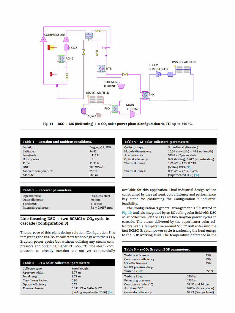
Based on the results obtained for the DSG thorn s CO2 solar power
plantswithout ReHeating (Configuration 2) we designed other
solar power plant layout for decreasing SF and HXs total
capital investment cost and increasing net plant efficiency
The target is introducing a Single ReHeating stage in Config
uration 2 another turbine for maximizing the plant effi
ciency as demonstrated by [MIT Dostal 2004] Also we
maintained the main SF with DSG and the additional
ReHeating SFwill be integrated byMS fieldwith PTC or LF solar
collectors The innovative dual loops plant Configuration 4
layout is illustrated in Fig 11
Results
Net plant efficiency at design-point
In the legacy PTC solar power plants like Andasol 1 (Spain)
the HTF was synthetic oil with an operating limit around
390 C to avoid any oil degradation For this reason the live
steam operating parameters were limited to 380 C and
100 bar at turbine inlet With these conditions and a legacy
Rankine power cycle with Reheating and only 3 low pressure
feed water heater a deareator and 1 high pressure feed water
heater the net plant efficiency was around 35 With latest
Rankine power cycle configurations with same TIT 380 Cand 100 bar with Reheating 4 low pressure feed water
heaters a deareator 3 high pressure feed water heaters the
net plant efficiency is ~375
The state of the art DSG thorn Rankine power cycle with DRH
[24253940] also could provide net plant efficiency up to ~41
for TIT 550 C and two reheating stages at same tempera
ture see Table 10 This configuration could play an important
role in the next generation solar power plants because despite
the higher Brayton s CO2 solar power plants net efficiency the
material and equipment cost in the innovative s CO2 power
cycles should be optimized for being competitive with the
steam Rankine power plants with equipments made of car
bon steel
In this paper we considered as the reference plant the
DSG thorn Rankine technology without reheating as illustrated in
Figs 5 and 6 delivering live steam at 400 C 90 bar to the BOP
This configuration net plant efficiency is ~35 detailed results
are listed in Tables 6 and 7
With the innovative DSG thorn s CO2 (Configuration 1) pro
posed in this paper a net plant efficiency ~3665 is obtained
with same TIT 400 C and also BOP equipments size and
volume is reduced in comparison with legacy steam Rankine
turbines detailed results in Tables 6 and 7
If we increase TIT up to 550 C in DSG thorn Rankine solar
plants the net plant efficiency is increased up to 384 see
detailed results in Tables 8 and 9 If we substitute the Rankine
cycle with an s CO2 Brayton power cycle as in Configuration 2
the net plant efficiency is increased up to ~436 see detailed
results in Tables 8 and 9 The RC s CO2 cycle configuration is
the optimum one providing higher net plant efficiency If we
consider theMSthorn sCO2 solar plant configuration the net plant
efficiency is improved up to ~449 The difference between
MS and DSG sCO2 solar power plants is due to the steam
compressor electrical consumption The target is to optimize
the steam compressors industrial design in order to reduce as
much as possible the parasitic energy losses in the solar power
plant
It is very important to highlight the Configuration 1 and
Configuration 2 not include any Reheating stage after main
HP turbine constituting this issue a handicap in the final plant
performance Configuration 3 integrates a Single Reheating
stage and the plant performance at 550 C TIT is ~397 For
more details about the Configuration 3 performance see
Table 10
As explained in this paper the Configuration 4 was defined
for integrating a Single ReHeating stage in the Configuration
2 This plant design maximum net plant efficiency is for the
RC s CO2 power cycle ~457 much higher than the
maximum DSG thorn s CO2 (RC) solar plant with maximum effi
ciency 4368 see Configuration 4 performance results in
Tables 11 and 12
Solar field effective aperture area
The net plant efficiency is translated in this chapter into SF
aperture area savings For a comparison between different
solar plant configuration we define a parameter called Net
Unitary Power and calculated with the following mathemat
ical expression
[21] Kruger D Kruger J Sukchai S Breitzke P Rahbani MSchenk H et al Solar cogeneration with parabolic troughcollectors in TRESERT In 18th SolarPaces ConferenceMarrakech Morocco 2012
[22] Kruger D Kruger J Pandian Y OConnell B Feldhoff JFKarthikeyan R et al Experience with direct steam generationat the Kanchanaburi Solar Thermal Power Plant In 18thSolarPACES Conference Marrakech Morocco 2012
[23] Khenissi A Return of experience on transient behaviour atthe DSG Solar Thermal Power Plant in KanchanaburiThailand Beijing China SolarPaces 2014
[24] Hirsch T Khenissi A A systematic comparison on powerblock efficiencies for CSP plants with direct steamgeneration Las Vegas US SolarPaces 2013
[25] Coco Enrıquez L Mu~noz Anton J Martınez Val JMInnovations on direct steam generation in linear Fresnelcollectors Las Vegas US SolarPaces 2013
[26] Schoot PTR 70 4th Generation httpwwwschottcomcspenglishschott solar receivershtmlsofrac14ibericaamplangfrac14spanish [accessed on 201214]
[27] Maccari A Archimede Solar Energy Performance of directsteam generation solar receiver laboratory vs real plantBeijing China SolarPaces 2014 httpssolarpaces2014psedeprogram [accessed 200515]
[28] Turchi CS Ma Z Neises TW Wagner MJ Thermodynamicstudy of advanced supercritical carbon dioxide power cyclesfor concentrating solar power systems J Sol Energy EngNovember 2013135041007 1 ASME
[29] Neises T Turchi C A comparison of supercritical carbondioxide power cycle configurations with an emphasis on CSPapplications Las Vegas US SolarPaces 2013
[30] Iverson Brian D Conboy Thomas M Pasch James JKruizenga Alan M Supercritical CO2 Brayton cycles for solarthermal energy J Appl Energy 2013111957 70
[31] Turchi C Bing C Lausten M 10 MW supercritical CO2 turbinetest National Renewable energy Laboratory NREL DEEE0001589 01272014 USA
[32] Halimi Burhanuddin Suh Kune Y Computational analysis ofsupercritical CO2 Brayton cycle power conversion system forfusion reactor Energy Convers Manag 20126338 43Elsevier
[33] Span R Wagner W A new equation of state for carbonedioxide covering temperature to 1100 K at pressure up to 800MPa J Phys Chem Ref Data 199625(No 6)1509 96
[34] Burkholder F Kutscher C Heat loss testing of Schotts 2008PTR70 parabolic trough receiver report NRELTP 550 45633May 2009
[35] Solar Novatec SAM linear Fresnel solar boiler model SAMWebinar In NREL SAM Conference 2013
[36] Wright Steven A Conboy Thomas M Rochau Gary EOverview of supercritical CO2 power cycle development atSandia National Laboratories Columbus Ohio SandiaNational Lab October 25 27 2011
[37] Carlson MD Kruizenga AK Schalansky C Fleming DFSandia progress on advance heat exchangers for sCO2
Brayton cycles In 4th International s CO2 SymposiumPittsburgh Pennsylvania 2014
[38] Dyreby John Klein Sandford Nellis Gregory Reindl DouglasDesign considerations for supercritical carbon dioxidebrayton cycles with recompression J Eng Gas TurbinesPower Jul22 2014136(10)101710
[39] LCoco Enrıquez JMu~noz Anton JM Martınez ValrdquoNewGeneration Line Focusing Solar Power Plants with MoltenSalts and Supercritical Brayton power cyclesrdquo 4thInternational Conference on Nuclear and RenewableResources NURER 214 Turkey
[40] Coco Enrıquez L Mu~noz Anton J Martınez Val JMSupercritical steam power cycle for line focus solar powerplants Turkey NURER 2014
The Configuration 1 provides similar efficiency and net power output for similar solar field effective aperture area as obtained with molten salt solar collectors with supercritical carbon dioxide power cycle (recompression with main compression intercooling cycle provides 366 net efficiency for a maximum 400 o C turbine inlet) The second design solution (Configuration 2) net efficiency is not very much impacted for steam compressor electrical consumption recompression cycle net efficiency is 436 with steam solar field versus 4516 with molten salt solar field in both cases with 550o C turbine inlet The Configuration 3 performance is ~397 with two cascade Brayton power cycles with recompression and main compression intercooling Finally the Configuration 4 optimum plant performance is obtained for the recompression cycle with a net efficiency ~4577 and is constrained by the molten salt drawbacks (material corrosion material cost environmental impact etc)
Nomenclature
s CO2 supercritical carbon dioxide DSG direct steam generation BOP balance of plant CSP concentrating solar power plant DRH Direct ReHeating HP High Pressure Turbine HTF heat transfer fluid IAM incident angle modifier ISCC integrated combined cycle LCOE levelized cost of Energy LF linear Fresnel DNI direct normal irradiance NREL National Renewable Laboratory (USA) OT once through boiling mode in DSG PE 1 Puerto Errado 1 PE 2 Puerto Errado 2 PTC parabolic trough collector RC recirculation Boiling mode in DSG SAM system advisor model SF solar field
TES thermal energy storage system DISS direct solar steam DUKE Durchlaufkonzept e Entwicklung und Erprobung NREL National Renewable Laboratory (in US) TSE 1 Thai Solar Energy Co Ltd PSA Plataforma Solar de Almerıa SB simple sCO2 Brayton power cycle RC recompression sCO2 Brayton cycle PCRC partial cooling with recompression cycle RCMCI recompression with main compression
intercooling cycle LTR Low Temperature Recuperator HTR High Temperature Recuperator PHX primary heat exchanger RHX reheating heat exchanger ACHE air cooled heat exchanger HX heat exchanger TIT turbine inlet temperature HTC heat transfer coefficient U overall heat transfer coefficient A heat transferring area in heat exchanger UA heat exchanger conductance
Introduction
The most common steam boilers technology in conventional fossil power plants are the liquid water recirculation (RC) boilers with steam drums and once through (OT) steam boilers without steam drums the Benson boilers Concentrated Solar Power Plants (CSP) are gaining synergies from these fossil fuel boilers technologies adapting them to solar energy power plants and particularly substituting boiler tubes by solar receivers in Parabolic Troughs (PT) and in Linear Fresnel (LF) solar collectors This is the so called Direct Steam Generation (DSG) technology
The first DSG plant was built in US in 1870s by John Ericsson [1] A larger DSG plant with 1250 m2 of mirror area was built by Frank Shuman in Egypt [2] The plant delivered saturated steam at 10 bar for driving a pumping station Intensive research on DSG systems with the target of generating superheated steam started in the 1990s which finally led to the erection of the DISS test plant [3] at Plataforma Solar de Almerıa (PSA) located in Spain for adapting RC boiling mode in PTC solar collectors The DISS facility was the first test plant for DSG with a 500 m DSG loops based on LS3 solar collectors The main results of this project were a general proof of water boiling modes and evaluation of pressure losses in horizontal
tubes [4]Within the European INDIPET project two additional
Eurotrough 100 collectors were installed for increasing the
thermal power for testing the compact phase separators [5]
Further components tests have been performed in the pro
jects DIVA [6] and Real DISS and latter ones in a small test SF
connected to a coal fired power station in Carboneras Spain
for steam parameters up to 500 C and 110 bar were performed
[7] An integrated storage system composed by a Phase
Change Component (PCM) and a concrete storage systemwere
tested at this facility [89] Recently since 2012 to assess theOT
operation the DISS facility has been extended in the frame of
the DUKE project [10e13] and the equipments and instru
mentation retrofitted for delivering steam up to 110 bar
550 C The research project DUKE aims at the development
and demonstration of a commercially applicable OT boiling
mode in DSG solar collectors
In 2009 Novatec Solar commenced the operation of
14 MWe LF test facility Puerto Errado 1 (PE 1) located in
Clasparra Spain The two collector rows were first used for
demonstrating the Fresnel collector and the saturated steam
process for pressure up to about 50 bar [14] In 2011 an addi
tional superheater loop was erected and successfully tested
for temperatures of about 500 C [15] Also a LF with DSG
demonstration system is operated at the Themis solar energy
RampD platform in the Pyreneans [16] Areva Solar erected the
78 MWth Kimberlina test plant at Bakersfield California in
order to demonstrate its OT compact LF collector technology
[17] A 30 MWe electric plant based on Novatec Solars NOVA 1
LF collectors went into operation in early 2012 in Calasparra
Spain [1819] The same year a small solar boiler of 93 MWth
went into operation at the Liddell coal fired power station in
Australia [20]
Regarding PTC solar collectors with DSG after the DISS
project the most remarkable industrial facility was the Tre
sert PTC plant in Phitsanulok Thailand it went into operation
in 2012 demonstrating the co generation of electricity [21]
The worldsrsquo first large scale DSG plant based on PTC tech
nology went into operation in early 2012 in Kanchanburi
Thailand [2223] The plant delivers steam at 30 bar330 C to a
5 MW steam turbine The first plant experience confirmed the
system operated well even under transient Direct Normal
Irradiance (DNI)
Other recent development related with DSG in line
focusing collectors is the application of this technology to
avoid any intermediate heat exchanger in ReHeating steam
between High Pressure Turbine and Intermediate or Low
Pressure Turbine This technology is called Direct ReHeating
(DRH) see Refs [2425]
In relation to DSG receiver pipes selective coatingmaterial
are being developed for increasing SF steam temperature
delivered to Balance of Plant (BOP) We mention the company
Schott PTR70 solar receiver (4th Generation) operating up to
temperatures around 550 C [26] Also the company Archi
medes Solar developed the HCESHS 12 [27] receivers for DSG
technology The inner steel tube of the HCESHS 12 has ge
ometry and a thermo mechanical strength such as to opti
mize the performance and durability for the purpose of direct
steam generation to high pressure and temperature The
HCESHS 12 has been designed to operate with superheated
steam at pressures higher than 100 bar with a fluid
temperature of 550 C The HCESHS 12 uses pill getter into the
vacuum annulus This getter permits a safe and efficient
operation for the whole expected receiver life absorbing the
residual gases desorbed by the metal
DSG main advantages in relation to other Heat Transfer
Fluid (HTF) are no working fluid degradation a clean tech
nology with no environmental impact no Heat Exchanger
(HX) between Solar Field (SF) and BOP industrial scalable
already validated in commercial plants temperatures and
pressures at turbine inlet only limited by receivers and
headers mechanical stresses low piping corrosion and low
maintenance costs no heat tracing required to avoid HTF
solidification etc
In parallel to DSG technology development supercritical
fluid Brayton power cycles with supercritical Carbon Dioxide
(s CO2) as working fluid are maturing as the most promising
technology for increasing actual steam Rankine power cycles
efficiency and for reducing BOP foot print and costs The
ability of the s CO2 cycle to reach high efficiency comes from
the reduced compressor work as the compressor inlet condi
tions approach the critical point of CO2 The density of the
supercritical fluid increases dramatically The increased
density close to the critical point reduces the compressor
work
In 1997 an investigation of the s CO2 cycle for possible use
in new power plants was conducted at the Czech Technical
University in Prague Czech Republic [Petr et al 1997] The re
compression cycle with re heating gave the best cycle effi
ciency It was found that this type of cycle is mainly suited for
high temperature nuclear reactor application The work about
s CO2 Brayton cycles for power generation continued In the
United States the investigation of the recompression super
critical CO2 cycle was resumed in the year 2000 at MIT under
collaboration with INEEL An indirect supercritical CO2
recompression cycle was designed for a leadebismuth
eutectic cooled reactor [Dostal et al 2001] A net efficiency of
41was calculated for a compressor outlet pressure of 20MPa
and LBE reactor outlet temperature of 555 C At Argonne
National Laboratory the recompression cycle was evaluated
for the STAR LM reactor [Moisseytsev et al 2003] and at
INEEL the CO2 Brayton cycle with multiple inter coolers
operating at temperatures above 900 C is being investigated
for thermal spectrum gas cooled reactors [Oh 2002] both are
NERI projects s CO2 recompression cycles have been inves
tigated at MIT for several years beginning in 2000 Dostal in
2004 published an important reference thesis in this field
titled ldquoA supercritical Carbon Dioxide Cycle for Next Gener
ation Nuclear Reactorsrdquo Since 2007 a biannual Symposium
focus on s CO2 Power Cycle is being organized to advance this
technology The first Symposium was held at the MIT in 2007
and the most recent one in 2014 has just held in Pittsburgh
Pennsylvania US In 2013 was published by NREL in US a
study proposing different sCO2 Brayton power cycles config
urations for Concentrated Solar Power Plants (CSP) Four
Brayton power cycles arrangements were proposed [28e30]
Based on the results obtained for the DSG thorn s CO2 solar power
plantswithout ReHeating (Configuration 2) we designed other
solar power plant layout for decreasing SF and HXs total
capital investment cost and increasing net plant efficiency
The target is introducing a Single ReHeating stage in Config
uration 2 another turbine for maximizing the plant effi
ciency as demonstrated by [MIT Dostal 2004] Also we
maintained the main SF with DSG and the additional
ReHeating SFwill be integrated byMS fieldwith PTC or LF solar
collectors The innovative dual loops plant Configuration 4
layout is illustrated in Fig 11
Results
Net plant efficiency at design-point
In the legacy PTC solar power plants like Andasol 1 (Spain)
the HTF was synthetic oil with an operating limit around
390 C to avoid any oil degradation For this reason the live
steam operating parameters were limited to 380 C and
100 bar at turbine inlet With these conditions and a legacy
Rankine power cycle with Reheating and only 3 low pressure
feed water heater a deareator and 1 high pressure feed water
heater the net plant efficiency was around 35 With latest
Rankine power cycle configurations with same TIT 380 Cand 100 bar with Reheating 4 low pressure feed water
heaters a deareator 3 high pressure feed water heaters the
net plant efficiency is ~375
The state of the art DSG thorn Rankine power cycle with DRH
[24253940] also could provide net plant efficiency up to ~41
for TIT 550 C and two reheating stages at same tempera
ture see Table 10 This configuration could play an important
role in the next generation solar power plants because despite
the higher Brayton s CO2 solar power plants net efficiency the
material and equipment cost in the innovative s CO2 power
cycles should be optimized for being competitive with the
steam Rankine power plants with equipments made of car
bon steel
In this paper we considered as the reference plant the
DSG thorn Rankine technology without reheating as illustrated in
Figs 5 and 6 delivering live steam at 400 C 90 bar to the BOP
This configuration net plant efficiency is ~35 detailed results
are listed in Tables 6 and 7
With the innovative DSG thorn s CO2 (Configuration 1) pro
posed in this paper a net plant efficiency ~3665 is obtained
with same TIT 400 C and also BOP equipments size and
volume is reduced in comparison with legacy steam Rankine
turbines detailed results in Tables 6 and 7
If we increase TIT up to 550 C in DSG thorn Rankine solar
plants the net plant efficiency is increased up to 384 see
detailed results in Tables 8 and 9 If we substitute the Rankine
cycle with an s CO2 Brayton power cycle as in Configuration 2
the net plant efficiency is increased up to ~436 see detailed
results in Tables 8 and 9 The RC s CO2 cycle configuration is
the optimum one providing higher net plant efficiency If we
consider theMSthorn sCO2 solar plant configuration the net plant
efficiency is improved up to ~449 The difference between
MS and DSG sCO2 solar power plants is due to the steam
compressor electrical consumption The target is to optimize
the steam compressors industrial design in order to reduce as
much as possible the parasitic energy losses in the solar power
plant
It is very important to highlight the Configuration 1 and
Configuration 2 not include any Reheating stage after main
HP turbine constituting this issue a handicap in the final plant
performance Configuration 3 integrates a Single Reheating
stage and the plant performance at 550 C TIT is ~397 For
more details about the Configuration 3 performance see
Table 10
As explained in this paper the Configuration 4 was defined
for integrating a Single ReHeating stage in the Configuration
2 This plant design maximum net plant efficiency is for the
RC s CO2 power cycle ~457 much higher than the
maximum DSG thorn s CO2 (RC) solar plant with maximum effi
ciency 4368 see Configuration 4 performance results in
Tables 11 and 12
Solar field effective aperture area
The net plant efficiency is translated in this chapter into SF
aperture area savings For a comparison between different
solar plant configuration we define a parameter called Net
Unitary Power and calculated with the following mathemat
ical expression
[21] Kruger D Kruger J Sukchai S Breitzke P Rahbani MSchenk H et al Solar cogeneration with parabolic troughcollectors in TRESERT In 18th SolarPaces ConferenceMarrakech Morocco 2012
[22] Kruger D Kruger J Pandian Y OConnell B Feldhoff JFKarthikeyan R et al Experience with direct steam generationat the Kanchanaburi Solar Thermal Power Plant In 18thSolarPACES Conference Marrakech Morocco 2012
[23] Khenissi A Return of experience on transient behaviour atthe DSG Solar Thermal Power Plant in KanchanaburiThailand Beijing China SolarPaces 2014
[24] Hirsch T Khenissi A A systematic comparison on powerblock efficiencies for CSP plants with direct steamgeneration Las Vegas US SolarPaces 2013
[25] Coco Enrıquez L Mu~noz Anton J Martınez Val JMInnovations on direct steam generation in linear Fresnelcollectors Las Vegas US SolarPaces 2013
[26] Schoot PTR 70 4th Generation httpwwwschottcomcspenglishschott solar receivershtmlsofrac14ibericaamplangfrac14spanish [accessed on 201214]
[27] Maccari A Archimede Solar Energy Performance of directsteam generation solar receiver laboratory vs real plantBeijing China SolarPaces 2014 httpssolarpaces2014psedeprogram [accessed 200515]
[28] Turchi CS Ma Z Neises TW Wagner MJ Thermodynamicstudy of advanced supercritical carbon dioxide power cyclesfor concentrating solar power systems J Sol Energy EngNovember 2013135041007 1 ASME
[29] Neises T Turchi C A comparison of supercritical carbondioxide power cycle configurations with an emphasis on CSPapplications Las Vegas US SolarPaces 2013
[30] Iverson Brian D Conboy Thomas M Pasch James JKruizenga Alan M Supercritical CO2 Brayton cycles for solarthermal energy J Appl Energy 2013111957 70
[31] Turchi C Bing C Lausten M 10 MW supercritical CO2 turbinetest National Renewable energy Laboratory NREL DEEE0001589 01272014 USA
[32] Halimi Burhanuddin Suh Kune Y Computational analysis ofsupercritical CO2 Brayton cycle power conversion system forfusion reactor Energy Convers Manag 20126338 43Elsevier
[33] Span R Wagner W A new equation of state for carbonedioxide covering temperature to 1100 K at pressure up to 800MPa J Phys Chem Ref Data 199625(No 6)1509 96
[34] Burkholder F Kutscher C Heat loss testing of Schotts 2008PTR70 parabolic trough receiver report NRELTP 550 45633May 2009
[35] Solar Novatec SAM linear Fresnel solar boiler model SAMWebinar In NREL SAM Conference 2013
[36] Wright Steven A Conboy Thomas M Rochau Gary EOverview of supercritical CO2 power cycle development atSandia National Laboratories Columbus Ohio SandiaNational Lab October 25 27 2011
[37] Carlson MD Kruizenga AK Schalansky C Fleming DFSandia progress on advance heat exchangers for sCO2
Brayton cycles In 4th International s CO2 SymposiumPittsburgh Pennsylvania 2014
[38] Dyreby John Klein Sandford Nellis Gregory Reindl DouglasDesign considerations for supercritical carbon dioxidebrayton cycles with recompression J Eng Gas TurbinesPower Jul22 2014136(10)101710
[39] LCoco Enrıquez JMu~noz Anton JM Martınez ValrdquoNewGeneration Line Focusing Solar Power Plants with MoltenSalts and Supercritical Brayton power cyclesrdquo 4thInternational Conference on Nuclear and RenewableResources NURER 214 Turkey
[40] Coco Enrıquez L Mu~noz Anton J Martınez Val JMSupercritical steam power cycle for line focus solar powerplants Turkey NURER 2014
development is headed by NREL in US designing and con
structing a real 10 MWe facility for power generation see
Ref [31]
Adaptation s CO2 Brayton cycles to interface with various
heat sources will be imperative for its adoption as an industry
manufactured technology Interfacing the solar resource with
a s CO2 Brayton cycle requires a receiver to absorb the solar
thermal energy from the incident concentrated flux and
transfer the energy to a transport media This paper is focus
on integrating DSG in linear solar collectors (PTC and LF) with
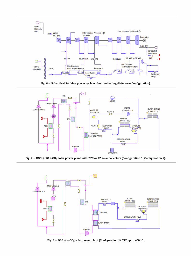
s CO2 Brayton power cycles see Fig 7 For this purpose four
DSG thorn s CO2 power plants configurations are proposed see
Based on the results obtained for the DSG thorn s CO2 solar power
plantswithout ReHeating (Configuration 2) we designed other
solar power plant layout for decreasing SF and HXs total
capital investment cost and increasing net plant efficiency
The target is introducing a Single ReHeating stage in Config
uration 2 another turbine for maximizing the plant effi
ciency as demonstrated by [MIT Dostal 2004] Also we
maintained the main SF with DSG and the additional
ReHeating SFwill be integrated byMS fieldwith PTC or LF solar
collectors The innovative dual loops plant Configuration 4
layout is illustrated in Fig 11
Results
Net plant efficiency at design-point
In the legacy PTC solar power plants like Andasol 1 (Spain)
the HTF was synthetic oil with an operating limit around
390 C to avoid any oil degradation For this reason the live
steam operating parameters were limited to 380 C and
100 bar at turbine inlet With these conditions and a legacy
Rankine power cycle with Reheating and only 3 low pressure
feed water heater a deareator and 1 high pressure feed water
heater the net plant efficiency was around 35 With latest
Rankine power cycle configurations with same TIT 380 Cand 100 bar with Reheating 4 low pressure feed water
heaters a deareator 3 high pressure feed water heaters the
net plant efficiency is ~375
The state of the art DSG thorn Rankine power cycle with DRH
[24253940] also could provide net plant efficiency up to ~41
for TIT 550 C and two reheating stages at same tempera
ture see Table 10 This configuration could play an important
role in the next generation solar power plants because despite
the higher Brayton s CO2 solar power plants net efficiency the
material and equipment cost in the innovative s CO2 power
cycles should be optimized for being competitive with the
steam Rankine power plants with equipments made of car
bon steel
In this paper we considered as the reference plant the
DSG thorn Rankine technology without reheating as illustrated in
Figs 5 and 6 delivering live steam at 400 C 90 bar to the BOP
This configuration net plant efficiency is ~35 detailed results
are listed in Tables 6 and 7
With the innovative DSG thorn s CO2 (Configuration 1) pro
posed in this paper a net plant efficiency ~3665 is obtained
with same TIT 400 C and also BOP equipments size and
volume is reduced in comparison with legacy steam Rankine
turbines detailed results in Tables 6 and 7
If we increase TIT up to 550 C in DSG thorn Rankine solar
plants the net plant efficiency is increased up to 384 see
detailed results in Tables 8 and 9 If we substitute the Rankine
cycle with an s CO2 Brayton power cycle as in Configuration 2
the net plant efficiency is increased up to ~436 see detailed
results in Tables 8 and 9 The RC s CO2 cycle configuration is
the optimum one providing higher net plant efficiency If we
consider theMSthorn sCO2 solar plant configuration the net plant
efficiency is improved up to ~449 The difference between
MS and DSG sCO2 solar power plants is due to the steam
compressor electrical consumption The target is to optimize
the steam compressors industrial design in order to reduce as
much as possible the parasitic energy losses in the solar power
plant
It is very important to highlight the Configuration 1 and
Configuration 2 not include any Reheating stage after main
HP turbine constituting this issue a handicap in the final plant
performance Configuration 3 integrates a Single Reheating
stage and the plant performance at 550 C TIT is ~397 For
more details about the Configuration 3 performance see
Table 10
As explained in this paper the Configuration 4 was defined
for integrating a Single ReHeating stage in the Configuration
2 This plant design maximum net plant efficiency is for the
RC s CO2 power cycle ~457 much higher than the
maximum DSG thorn s CO2 (RC) solar plant with maximum effi
ciency 4368 see Configuration 4 performance results in
Tables 11 and 12
Solar field effective aperture area
The net plant efficiency is translated in this chapter into SF
aperture area savings For a comparison between different
solar plant configuration we define a parameter called Net
Unitary Power and calculated with the following mathemat
ical expression
[21] Kruger D Kruger J Sukchai S Breitzke P Rahbani MSchenk H et al Solar cogeneration with parabolic troughcollectors in TRESERT In 18th SolarPaces ConferenceMarrakech Morocco 2012
[22] Kruger D Kruger J Pandian Y OConnell B Feldhoff JFKarthikeyan R et al Experience with direct steam generationat the Kanchanaburi Solar Thermal Power Plant In 18thSolarPACES Conference Marrakech Morocco 2012
[23] Khenissi A Return of experience on transient behaviour atthe DSG Solar Thermal Power Plant in KanchanaburiThailand Beijing China SolarPaces 2014
[24] Hirsch T Khenissi A A systematic comparison on powerblock efficiencies for CSP plants with direct steamgeneration Las Vegas US SolarPaces 2013
[25] Coco Enrıquez L Mu~noz Anton J Martınez Val JMInnovations on direct steam generation in linear Fresnelcollectors Las Vegas US SolarPaces 2013
[26] Schoot PTR 70 4th Generation httpwwwschottcomcspenglishschott solar receivershtmlsofrac14ibericaamplangfrac14spanish [accessed on 201214]
[27] Maccari A Archimede Solar Energy Performance of directsteam generation solar receiver laboratory vs real plantBeijing China SolarPaces 2014 httpssolarpaces2014psedeprogram [accessed 200515]
[28] Turchi CS Ma Z Neises TW Wagner MJ Thermodynamicstudy of advanced supercritical carbon dioxide power cyclesfor concentrating solar power systems J Sol Energy EngNovember 2013135041007 1 ASME
[29] Neises T Turchi C A comparison of supercritical carbondioxide power cycle configurations with an emphasis on CSPapplications Las Vegas US SolarPaces 2013
[30] Iverson Brian D Conboy Thomas M Pasch James JKruizenga Alan M Supercritical CO2 Brayton cycles for solarthermal energy J Appl Energy 2013111957 70
[31] Turchi C Bing C Lausten M 10 MW supercritical CO2 turbinetest National Renewable energy Laboratory NREL DEEE0001589 01272014 USA
[32] Halimi Burhanuddin Suh Kune Y Computational analysis ofsupercritical CO2 Brayton cycle power conversion system forfusion reactor Energy Convers Manag 20126338 43Elsevier
[33] Span R Wagner W A new equation of state for carbonedioxide covering temperature to 1100 K at pressure up to 800MPa J Phys Chem Ref Data 199625(No 6)1509 96
[34] Burkholder F Kutscher C Heat loss testing of Schotts 2008PTR70 parabolic trough receiver report NRELTP 550 45633May 2009
[35] Solar Novatec SAM linear Fresnel solar boiler model SAMWebinar In NREL SAM Conference 2013
[36] Wright Steven A Conboy Thomas M Rochau Gary EOverview of supercritical CO2 power cycle development atSandia National Laboratories Columbus Ohio SandiaNational Lab October 25 27 2011
[37] Carlson MD Kruizenga AK Schalansky C Fleming DFSandia progress on advance heat exchangers for sCO2
Brayton cycles In 4th International s CO2 SymposiumPittsburgh Pennsylvania 2014
[38] Dyreby John Klein Sandford Nellis Gregory Reindl DouglasDesign considerations for supercritical carbon dioxidebrayton cycles with recompression J Eng Gas TurbinesPower Jul22 2014136(10)101710
[39] LCoco Enrıquez JMu~noz Anton JM Martınez ValrdquoNewGeneration Line Focusing Solar Power Plants with MoltenSalts and Supercritical Brayton power cyclesrdquo 4thInternational Conference on Nuclear and RenewableResources NURER 214 Turkey
[40] Coco Enrıquez L Mu~noz Anton J Martınez Val JMSupercritical steam power cycle for line focus solar powerplants Turkey NURER 2014
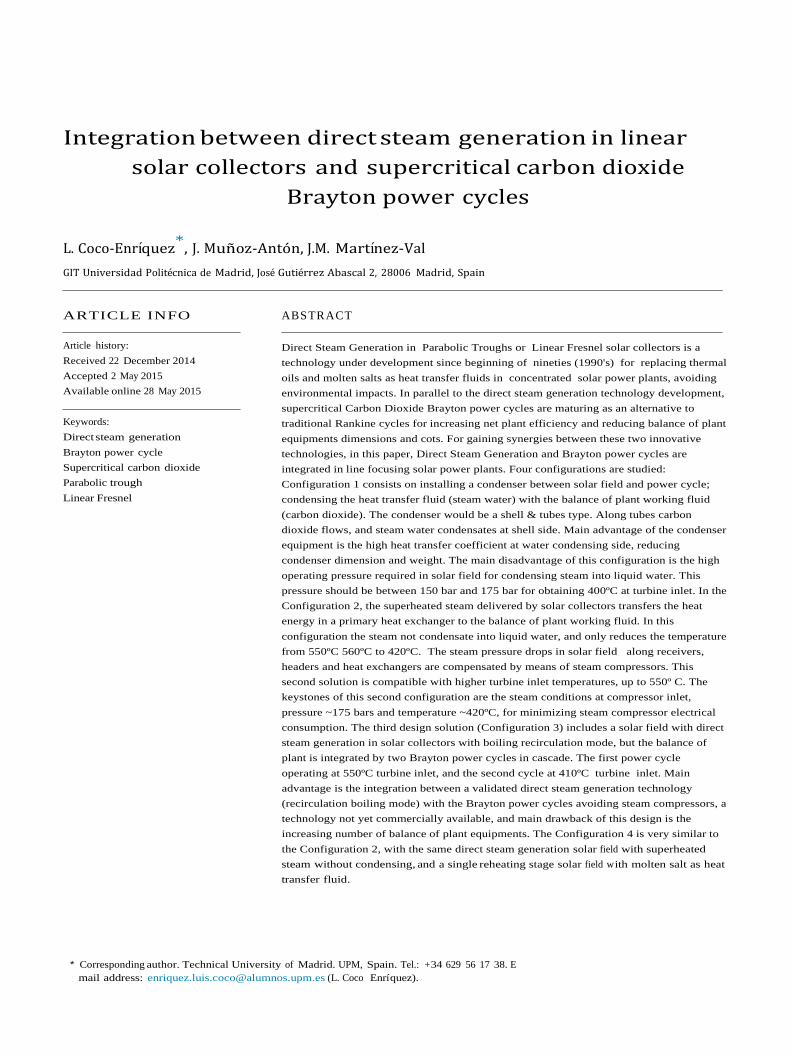
Fig 3 e Partial cooling with recompression Brayton s-CO2
power cycle (PCRC)
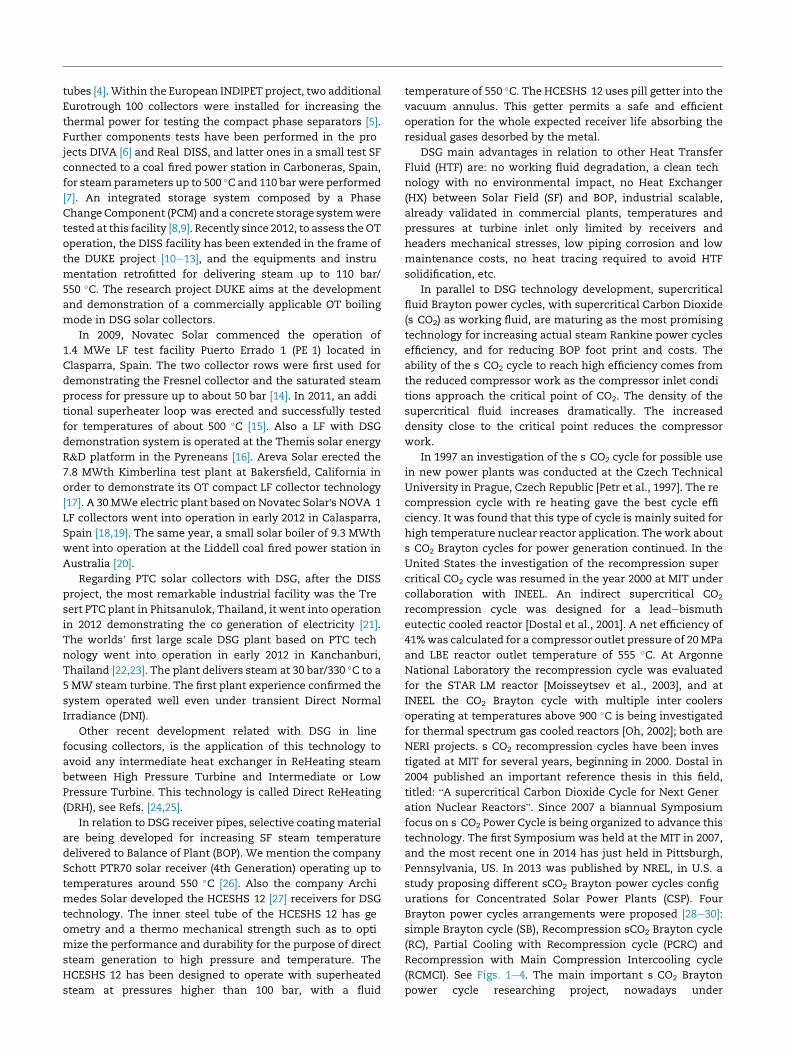
Fig 4 e Recompression with main compression
intercooling s-CO2 Brayton power cycle (RCMCI)
Modelling assumptions
All solar power plants simulated in this study were modelled
considering the performances parameter summarised in the
following Tables 1e5
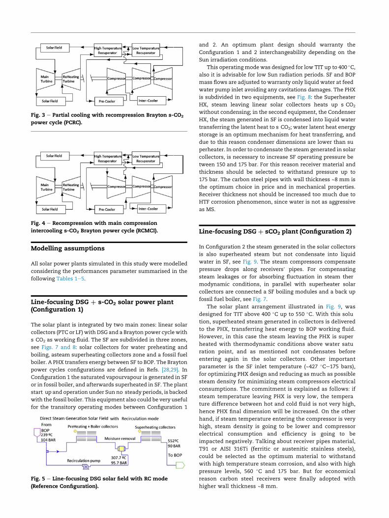
Line-focusing DSG thorn s-CO2 solar power plant(Configuration 1)
The solar plant is integrated by two main zones linear solar
collectors (PTC or LF) with DSG and a Brayton power cycle with
s CO2 as working fluid The SF are subdivided in three zones
see Figs 7 and 8 solar collectors for water preheating and
boiling asteam superheating collectors zone and a fossil fuel
boiler A PHX transfers energy between SF to BOP The Brayton
power cycles configurations are defined in Refs [2829] In
Configuration 1 the saturated vapourvapour is generated in SF
or in fossil boiler and afterwards superheated in SF The plant
start up and operation under Sun no steady periods is backed
with the fossil boiler This equipment also could be very useful
for the transitory operating modes between Configuration 1
Fig 5 e Line-focusing DSG solar field with RC mode
(Reference Configuration)
and 2 An optimum plant design should warranty the
Configuration 1 and 2 interchangeability depending on the
Sun irradiation conditions
This operatingmode was designed for low TIT up to 400 Calso it is advisable for low Sun radiation periods SF and BOP
mass flows are adjusted to warranty only liquid water at feed
water pump inlet avoiding any cavitations damages The PHX
is subdivided in two equipments see Fig 8 the Superheater
HX steam leaving linear solar collectors heats up s CO2
without condensing in the second equipment the Condenser
HX the steam generated in SF is condensed into liquid water
transferring the latent heat to s CO2 water latent heat energy
storage is an optimum mechanism for heat transferring and
due to this reason condenser dimensions are lower than su
perheater In order to condensate the steam generated in solar
collectors is necessary to increase SF operating pressure be
tween 150 and 175 bar For this reason receiver material and
thickness should be selected to withstand pressure up to
175 bar The carbon steel pipes with wall thickness ~8 mm is
the optimum choice in price and in mechanical properties
Receiver thickness not should be increased too much due to
HTF corrosion phenomenon since water is not as aggressive
Based on the results obtained for the DSG thorn s CO2 solar power
plantswithout ReHeating (Configuration 2) we designed other
solar power plant layout for decreasing SF and HXs total
capital investment cost and increasing net plant efficiency
The target is introducing a Single ReHeating stage in Config
uration 2 another turbine for maximizing the plant effi
ciency as demonstrated by [MIT Dostal 2004] Also we
maintained the main SF with DSG and the additional
ReHeating SFwill be integrated byMS fieldwith PTC or LF solar
collectors The innovative dual loops plant Configuration 4
layout is illustrated in Fig 11
Results
Net plant efficiency at design-point
In the legacy PTC solar power plants like Andasol 1 (Spain)
the HTF was synthetic oil with an operating limit around
390 C to avoid any oil degradation For this reason the live
steam operating parameters were limited to 380 C and
100 bar at turbine inlet With these conditions and a legacy
Rankine power cycle with Reheating and only 3 low pressure
feed water heater a deareator and 1 high pressure feed water
heater the net plant efficiency was around 35 With latest
Rankine power cycle configurations with same TIT 380 Cand 100 bar with Reheating 4 low pressure feed water
heaters a deareator 3 high pressure feed water heaters the
net plant efficiency is ~375
The state of the art DSG thorn Rankine power cycle with DRH
[24253940] also could provide net plant efficiency up to ~41
for TIT 550 C and two reheating stages at same tempera
ture see Table 10 This configuration could play an important
role in the next generation solar power plants because despite
the higher Brayton s CO2 solar power plants net efficiency the
material and equipment cost in the innovative s CO2 power
cycles should be optimized for being competitive with the
steam Rankine power plants with equipments made of car
bon steel
In this paper we considered as the reference plant the
DSG thorn Rankine technology without reheating as illustrated in
Figs 5 and 6 delivering live steam at 400 C 90 bar to the BOP
This configuration net plant efficiency is ~35 detailed results
are listed in Tables 6 and 7
With the innovative DSG thorn s CO2 (Configuration 1) pro
posed in this paper a net plant efficiency ~3665 is obtained
with same TIT 400 C and also BOP equipments size and
volume is reduced in comparison with legacy steam Rankine
turbines detailed results in Tables 6 and 7
If we increase TIT up to 550 C in DSG thorn Rankine solar
plants the net plant efficiency is increased up to 384 see
detailed results in Tables 8 and 9 If we substitute the Rankine
cycle with an s CO2 Brayton power cycle as in Configuration 2
the net plant efficiency is increased up to ~436 see detailed
results in Tables 8 and 9 The RC s CO2 cycle configuration is
the optimum one providing higher net plant efficiency If we
consider theMSthorn sCO2 solar plant configuration the net plant
efficiency is improved up to ~449 The difference between
MS and DSG sCO2 solar power plants is due to the steam
compressor electrical consumption The target is to optimize
the steam compressors industrial design in order to reduce as
much as possible the parasitic energy losses in the solar power
plant
It is very important to highlight the Configuration 1 and
Configuration 2 not include any Reheating stage after main
HP turbine constituting this issue a handicap in the final plant
performance Configuration 3 integrates a Single Reheating
stage and the plant performance at 550 C TIT is ~397 For
more details about the Configuration 3 performance see
Table 10
As explained in this paper the Configuration 4 was defined
for integrating a Single ReHeating stage in the Configuration
2 This plant design maximum net plant efficiency is for the
RC s CO2 power cycle ~457 much higher than the
maximum DSG thorn s CO2 (RC) solar plant with maximum effi
ciency 4368 see Configuration 4 performance results in
Tables 11 and 12
Solar field effective aperture area
The net plant efficiency is translated in this chapter into SF
aperture area savings For a comparison between different
solar plant configuration we define a parameter called Net
Unitary Power and calculated with the following mathemat
ical expression
[21] Kruger D Kruger J Sukchai S Breitzke P Rahbani MSchenk H et al Solar cogeneration with parabolic troughcollectors in TRESERT In 18th SolarPaces ConferenceMarrakech Morocco 2012
[22] Kruger D Kruger J Pandian Y OConnell B Feldhoff JFKarthikeyan R et al Experience with direct steam generationat the Kanchanaburi Solar Thermal Power Plant In 18thSolarPACES Conference Marrakech Morocco 2012
[23] Khenissi A Return of experience on transient behaviour atthe DSG Solar Thermal Power Plant in KanchanaburiThailand Beijing China SolarPaces 2014
[24] Hirsch T Khenissi A A systematic comparison on powerblock efficiencies for CSP plants with direct steamgeneration Las Vegas US SolarPaces 2013
[25] Coco Enrıquez L Mu~noz Anton J Martınez Val JMInnovations on direct steam generation in linear Fresnelcollectors Las Vegas US SolarPaces 2013
[26] Schoot PTR 70 4th Generation httpwwwschottcomcspenglishschott solar receivershtmlsofrac14ibericaamplangfrac14spanish [accessed on 201214]
[27] Maccari A Archimede Solar Energy Performance of directsteam generation solar receiver laboratory vs real plantBeijing China SolarPaces 2014 httpssolarpaces2014psedeprogram [accessed 200515]
[28] Turchi CS Ma Z Neises TW Wagner MJ Thermodynamicstudy of advanced supercritical carbon dioxide power cyclesfor concentrating solar power systems J Sol Energy EngNovember 2013135041007 1 ASME
[29] Neises T Turchi C A comparison of supercritical carbondioxide power cycle configurations with an emphasis on CSPapplications Las Vegas US SolarPaces 2013
[30] Iverson Brian D Conboy Thomas M Pasch James JKruizenga Alan M Supercritical CO2 Brayton cycles for solarthermal energy J Appl Energy 2013111957 70
[31] Turchi C Bing C Lausten M 10 MW supercritical CO2 turbinetest National Renewable energy Laboratory NREL DEEE0001589 01272014 USA
[32] Halimi Burhanuddin Suh Kune Y Computational analysis ofsupercritical CO2 Brayton cycle power conversion system forfusion reactor Energy Convers Manag 20126338 43Elsevier
[33] Span R Wagner W A new equation of state for carbonedioxide covering temperature to 1100 K at pressure up to 800MPa J Phys Chem Ref Data 199625(No 6)1509 96
[34] Burkholder F Kutscher C Heat loss testing of Schotts 2008PTR70 parabolic trough receiver report NRELTP 550 45633May 2009
[35] Solar Novatec SAM linear Fresnel solar boiler model SAMWebinar In NREL SAM Conference 2013
[36] Wright Steven A Conboy Thomas M Rochau Gary EOverview of supercritical CO2 power cycle development atSandia National Laboratories Columbus Ohio SandiaNational Lab October 25 27 2011
[37] Carlson MD Kruizenga AK Schalansky C Fleming DFSandia progress on advance heat exchangers for sCO2
Brayton cycles In 4th International s CO2 SymposiumPittsburgh Pennsylvania 2014
[38] Dyreby John Klein Sandford Nellis Gregory Reindl DouglasDesign considerations for supercritical carbon dioxidebrayton cycles with recompression J Eng Gas TurbinesPower Jul22 2014136(10)101710
[39] LCoco Enrıquez JMu~noz Anton JM Martınez ValrdquoNewGeneration Line Focusing Solar Power Plants with MoltenSalts and Supercritical Brayton power cyclesrdquo 4thInternational Conference on Nuclear and RenewableResources NURER 214 Turkey
[40] Coco Enrıquez L Mu~noz Anton J Martınez Val JMSupercritical steam power cycle for line focus solar powerplants Turkey NURER 2014
Fig 6 e Subcritical Rankine power cycle without reheating (Reference Configuration)
Fig 7 e DSG thorn RC s-CO2 solar power plant with PTC or LF solar collectors (Configuration 1 Configuration 2)
Fig 8 e DSG thorn s-CO2 solar power plant (Configuration 1) TIT up to 400 C
Fig 9 e DSG thorn s-CO2 solar power plant (Configuration 2) TIT from 400 C up to 550 C
As mentioned in Configuration 2 steam compressor
electrical consumption should be optimized to avoid a great
impact in net plant efficiency In this sense another key
parameter is the maximum mass flux in receivers This
parameter was limited to 1000 kgm2s in LF collectors and
up to 850 kgm2s in PTC collectors Limiting mass flux
warranties maximum pressure drop in SF and hence pro
vides an optimum SF arrangement design Also steam
compressor electrical consumption depends on the SF
Fig 10 e DSG thorn s-CO2 solar power plant
operating pressure The higher pressure values in SF in
crease steam density and reduces compressor work How
ever increasing SF operating pressure requires high cost
material in receivers pipes and higher pipe wall thickness
and adequate movable joint design An economical study is
necessary to conclude the optimum SF operating pressure in
relation with material cost Higher pressure is most suitable
for LF collectors without any movable joint and stiffer
piping design
(Configuration 3) TIT up to 550 C
primary heat exchanger in the first power cycle is in the range
of 550 C and 410 C This first cycle also integrates a single
reheating stage for heating the working fluid up to 550 C after
the High Pressure turbine (HP) The steam vapor leaving the
primary heat exchanger in the first cycle will go into the sec
ond power cycle at a temperature around 410 C In this sec
ond power cycle the water steam will be condensate into
saturated liquid water at 350 C for this purpose the SF
operating pressure is 175 bar (water saturation temperature
35463 C) Main advantage of Configuration 3 is the plant
performance very similar than the DSG thorn Rankine solar
power plants with Reheating ~40
There are some design parameters and ratios to respect in
this Configuration 3 for obtaining the optimum plant perfor
mance The first one is the relation between s CO2 the mass
flow in the cycle 1 and the s CO2 mass flow in the cycle 2 this
relation should be ~62 in order for obtaining saturated liquid
water at SF inlet Another two important parameters should
be fixed the temperatures in the PHX1 (410 C steam outlet
and 550 C s CO2 outlet) see Fig 10 The steamwater splitting
fraction to the RHX in the first power cycle is 55 of the total
superheated steam flow delivered by the DSG SF And finally
the flow fraction before compressing in both cycles was fixed
to 60e40
Also the Configuration 3 performance could be optimized
fixing the recuperators conductance (LTR and HTR) in both
cascade cycles This is a practice proposed in Ref [38] and
increases the net plant efficiency ~1 for this particular case
Based on the results obtained for the DSG thorn s CO2 solar power
plantswithout ReHeating (Configuration 2) we designed other
solar power plant layout for decreasing SF and HXs total
capital investment cost and increasing net plant efficiency
The target is introducing a Single ReHeating stage in Config
uration 2 another turbine for maximizing the plant effi
ciency as demonstrated by [MIT Dostal 2004] Also we
maintained the main SF with DSG and the additional
ReHeating SFwill be integrated byMS fieldwith PTC or LF solar
collectors The innovative dual loops plant Configuration 4
layout is illustrated in Fig 11
Results
Net plant efficiency at design-point
In the legacy PTC solar power plants like Andasol 1 (Spain)
the HTF was synthetic oil with an operating limit around
390 C to avoid any oil degradation For this reason the live
steam operating parameters were limited to 380 C and
100 bar at turbine inlet With these conditions and a legacy
Rankine power cycle with Reheating and only 3 low pressure
feed water heater a deareator and 1 high pressure feed water
heater the net plant efficiency was around 35 With latest
Rankine power cycle configurations with same TIT 380 Cand 100 bar with Reheating 4 low pressure feed water
heaters a deareator 3 high pressure feed water heaters the
net plant efficiency is ~375
The state of the art DSG thorn Rankine power cycle with DRH
[24253940] also could provide net plant efficiency up to ~41
for TIT 550 C and two reheating stages at same tempera
ture see Table 10 This configuration could play an important
role in the next generation solar power plants because despite
the higher Brayton s CO2 solar power plants net efficiency the
material and equipment cost in the innovative s CO2 power
cycles should be optimized for being competitive with the
steam Rankine power plants with equipments made of car
bon steel
In this paper we considered as the reference plant the
DSG thorn Rankine technology without reheating as illustrated in
Figs 5 and 6 delivering live steam at 400 C 90 bar to the BOP
This configuration net plant efficiency is ~35 detailed results
are listed in Tables 6 and 7
With the innovative DSG thorn s CO2 (Configuration 1) pro
posed in this paper a net plant efficiency ~3665 is obtained
with same TIT 400 C and also BOP equipments size and
volume is reduced in comparison with legacy steam Rankine
turbines detailed results in Tables 6 and 7
If we increase TIT up to 550 C in DSG thorn Rankine solar
plants the net plant efficiency is increased up to 384 see
detailed results in Tables 8 and 9 If we substitute the Rankine
cycle with an s CO2 Brayton power cycle as in Configuration 2
the net plant efficiency is increased up to ~436 see detailed
results in Tables 8 and 9 The RC s CO2 cycle configuration is
the optimum one providing higher net plant efficiency If we
consider theMSthorn sCO2 solar plant configuration the net plant
efficiency is improved up to ~449 The difference between
MS and DSG sCO2 solar power plants is due to the steam
compressor electrical consumption The target is to optimize
the steam compressors industrial design in order to reduce as
much as possible the parasitic energy losses in the solar power
plant
It is very important to highlight the Configuration 1 and
Configuration 2 not include any Reheating stage after main
HP turbine constituting this issue a handicap in the final plant
performance Configuration 3 integrates a Single Reheating
stage and the plant performance at 550 C TIT is ~397 For
more details about the Configuration 3 performance see
Table 10
As explained in this paper the Configuration 4 was defined
for integrating a Single ReHeating stage in the Configuration
2 This plant design maximum net plant efficiency is for the
RC s CO2 power cycle ~457 much higher than the
maximum DSG thorn s CO2 (RC) solar plant with maximum effi
ciency 4368 see Configuration 4 performance results in
Tables 11 and 12
Solar field effective aperture area
The net plant efficiency is translated in this chapter into SF
aperture area savings For a comparison between different
solar plant configuration we define a parameter called Net
Unitary Power and calculated with the following mathemat
ical expression
[21] Kruger D Kruger J Sukchai S Breitzke P Rahbani MSchenk H et al Solar cogeneration with parabolic troughcollectors in TRESERT In 18th SolarPaces ConferenceMarrakech Morocco 2012
[22] Kruger D Kruger J Pandian Y OConnell B Feldhoff JFKarthikeyan R et al Experience with direct steam generationat the Kanchanaburi Solar Thermal Power Plant In 18thSolarPACES Conference Marrakech Morocco 2012
[23] Khenissi A Return of experience on transient behaviour atthe DSG Solar Thermal Power Plant in KanchanaburiThailand Beijing China SolarPaces 2014
[24] Hirsch T Khenissi A A systematic comparison on powerblock efficiencies for CSP plants with direct steamgeneration Las Vegas US SolarPaces 2013
[25] Coco Enrıquez L Mu~noz Anton J Martınez Val JMInnovations on direct steam generation in linear Fresnelcollectors Las Vegas US SolarPaces 2013
[26] Schoot PTR 70 4th Generation httpwwwschottcomcspenglishschott solar receivershtmlsofrac14ibericaamplangfrac14spanish [accessed on 201214]
[27] Maccari A Archimede Solar Energy Performance of directsteam generation solar receiver laboratory vs real plantBeijing China SolarPaces 2014 httpssolarpaces2014psedeprogram [accessed 200515]
[28] Turchi CS Ma Z Neises TW Wagner MJ Thermodynamicstudy of advanced supercritical carbon dioxide power cyclesfor concentrating solar power systems J Sol Energy EngNovember 2013135041007 1 ASME
[29] Neises T Turchi C A comparison of supercritical carbondioxide power cycle configurations with an emphasis on CSPapplications Las Vegas US SolarPaces 2013
[30] Iverson Brian D Conboy Thomas M Pasch James JKruizenga Alan M Supercritical CO2 Brayton cycles for solarthermal energy J Appl Energy 2013111957 70
[31] Turchi C Bing C Lausten M 10 MW supercritical CO2 turbinetest National Renewable energy Laboratory NREL DEEE0001589 01272014 USA
[32] Halimi Burhanuddin Suh Kune Y Computational analysis ofsupercritical CO2 Brayton cycle power conversion system forfusion reactor Energy Convers Manag 20126338 43Elsevier
[33] Span R Wagner W A new equation of state for carbonedioxide covering temperature to 1100 K at pressure up to 800MPa J Phys Chem Ref Data 199625(No 6)1509 96
[34] Burkholder F Kutscher C Heat loss testing of Schotts 2008PTR70 parabolic trough receiver report NRELTP 550 45633May 2009
[35] Solar Novatec SAM linear Fresnel solar boiler model SAMWebinar In NREL SAM Conference 2013
[36] Wright Steven A Conboy Thomas M Rochau Gary EOverview of supercritical CO2 power cycle development atSandia National Laboratories Columbus Ohio SandiaNational Lab October 25 27 2011
[37] Carlson MD Kruizenga AK Schalansky C Fleming DFSandia progress on advance heat exchangers for sCO2
Brayton cycles In 4th International s CO2 SymposiumPittsburgh Pennsylvania 2014
[38] Dyreby John Klein Sandford Nellis Gregory Reindl DouglasDesign considerations for supercritical carbon dioxidebrayton cycles with recompression J Eng Gas TurbinesPower Jul22 2014136(10)101710
[39] LCoco Enrıquez JMu~noz Anton JM Martınez ValrdquoNewGeneration Line Focusing Solar Power Plants with MoltenSalts and Supercritical Brayton power cyclesrdquo 4thInternational Conference on Nuclear and RenewableResources NURER 214 Turkey
[40] Coco Enrıquez L Mu~noz Anton J Martınez Val JMSupercritical steam power cycle for line focus solar powerplants Turkey NURER 2014