Interconnection of own generation with an outside supply by means of resonant links (s.l.c.s) C.L. Beevers Indexing terms: Oil refining, Resonant links Abstract: This paper outlines the problems which may be encountered when adding a substantial amount of back-pressure generation to an existing industrial system. The selection of a particular system, including two resonant links, is described, together with factory and site performance tests of the links. 1 Background A very substantial programme of expansion has been taking place at the Shell UK oil refinery at Stanlow in recent years. As a result of the commissioning of various large new process plants, the electrical load of the refinery has grown in this period from about 20 MW to nearly 80 MW. As well as having a large electrical loading, petrochemical process plants also require large quantities of steam, particularly for process and tank heating. The new plants have thus also caused a similar rise in the demand for steam. Prior to the commencement of this expansion programme, a very thorough study was made of the utility supply systems within the refinery and particularly of the steam and electricity systems. At that time all electricity for the refinery was purchased from Manweb, and steam was raised in two medium-pressure (18 bar) boiler plants. It is, perhaps, worthwhile mentioning the main factors impinging on this study, and some of the alternative solutions which were considered. First, both the steam and electrical loads were expected to approximately treble over a ten-year period, in a more or less uniform way. However, there was no guarantee that the expansion plan for the refinery would proceed either exactly in line with, or to the level, forecast. Secondly, although the main intake substations had spare capacity already available, the refinery boiler plant was even then virtually fully loaded. Thirdly, the purchase of an additional 50 MW of elec- trical power would have cost over two million pounds per year at 1965 prices. This is not a complaint, merely a fact of life. With these basic factors in mind, the company, in conjunction with consulting engineers, examined in some detail various alternative solutions. In summary, these can be recorded as follows: (a) Continuing purchase of all electricity from Manweb, with some expansion of the main intake system; con- struction of additional medium-pressure boiler plant. (b) Installation of high-pressure boiler plant and back- pressure generators in a few (2—3) large stages, with high- voltage electrical backup from the grid (132 kV). (c) Installation of high-pressure boiler plant and back- pressure generators phased with the main steps of process plant expansion; interconnection with the grid via the existing intake substations. When reviewing these alternatives, and some variants, they Paper T334P, first received 19th April 1978 and in revised form 14th February 1979 Dr. Beevers was formerly with the Shell Stanlow Refinery, and is now with Shell International Gas, Shell Centre, London SEl 7NA, England ELECTRIC POWER APPLICATIONS, APRIL 1979, Vol. 2, No. 2 were of course considered in relation to one another rather than in isolation, and the main conclusions may in turn be summarised thus: (a) Although this was technically satisfactory, the other alternatives showed a much better return on capital invested, particularly because of the reduced amount of purchased electricity. (b) This solution had a number of drawbacks; in par- ticular a large proportion of the total capital expenditure had to be committed at the outset, instead of being phased, and maintenance and other shutdowns of the boiler and generator units would have a serious impact on process plant operation and imported power costs. (c) The advantages of this approach were essentially the opposite of the drawbacks of (a) and (b), i.e. the phasing of expenditure in line with process plant expansion, low operating costs and minimum effect of boiler/generator shutdowns on process plants and operating costs. However, a novel approach was required for the connection of the generating plant to th*e rest of the electrical system. As a concept, back-pressure power generation in a re- finery has some particular advantages, the main ones being: (i)low incremental capital cost for boiler plant, since medium-pressure boilers are needed anyway for process steam (ii)high overall efficiency (about 80%) since exhaust steam from the generator turbines is condensed in process plant and, hence, little fuel energy is wasted. One scarcely need to say that this last approach is the one which has actually been adopted. The new power station at the Stanlow refinery consists of six 121-926 tonne/h (120ton/h) 100 bar boilers (Fig. 1), each connected to a 10MW backpressure a.c. turbogenerator (Fig. 2). The Fig. 1 Stanlow: The new high-pressure boilers 51 0140-1327/79/020051 + 08 $01-50/0
Transcript
Interconnection of own generation with an outsidesupply by means of resonant links (s.l.c.s)
C.L. Beevers
Indexing terms: Oil refining, Resonant links
Abstract: This paper outlines the problems which may be encountered when adding a substantial amount ofback-pressure generation to an existing industrial system. The selection of a particular system, including tworesonant links, is described, together with factory and site performance tests of the links.
1 Background
A very substantial programme of expansion has been takingplace at the Shell UK oil refinery at Stanlow in recent years.As a result of the commissioning of various large newprocess plants, the electrical load of the refinery has grownin this period from about 20 MW to nearly 80 MW. As wellas having a large electrical loading, petrochemical processplants also require large quantities of steam, particularly forprocess and tank heating. The new plants have thus alsocaused a similar rise in the demand for steam.
Prior to the commencement of this expansion programme,a very thorough study was made of the utility supplysystems within the refinery and particularly of the steamand electricity systems. At that time all electricity for therefinery was purchased from Manweb, and steam was raisedin two medium-pressure (18 bar) boiler plants. It is, perhaps,worthwhile mentioning the main factors impinging on thisstudy, and some of the alternative solutions which wereconsidered.
First, both the steam and electrical loads were expectedto approximately treble over a ten-year period, in a moreor less uniform way. However, there was no guarantee thatthe expansion plan for the refinery would proceed eitherexactly in line with, or to the level, forecast.
Secondly, although the main intake substations hadspare capacity already available, the refinery boiler plantwas even then virtually fully loaded.
Thirdly, the purchase of an additional 50 MW of elec-trical power would have cost over two million pounds peryear at 1965 prices. This is not a complaint, merely a factof life.
With these basic factors in mind, the company, inconjunction with consulting engineers, examined in somedetail various alternative solutions. In summary, these canbe recorded as follows:
(a) Continuing purchase of all electricity from Manweb,with some expansion of the main intake system; con-struction of additional medium-pressure boiler plant.
(b) Installation of high-pressure boiler plant and back-pressure generators in a few (2—3) large stages, with high-voltage electrical backup from the grid (132 kV).
(c) Installation of high-pressure boiler plant and back-pressure generators phased with the main steps of processplant expansion; interconnection with the grid via theexisting intake substations.When reviewing these alternatives, and some variants, they
Paper T334P, first received 19th April 1978 and in revised form14th February 1979Dr. Beevers was formerly with the Shell Stanlow Refinery, and isnow with Shell International Gas, Shell Centre, London SEl 7NA,England
ELECTRIC POWER APPLICATIONS, APRIL 1979, Vol. 2, No. 2
were of course considered in relation to one another ratherthan in isolation, and the main conclusions may in turn besummarised thus:
(a) Although this was technically satisfactory, the otheralternatives showed a much better return on capital invested,particularly because of the reduced amount of purchasedelectricity.
(b) This solution had a number of drawbacks; in par-ticular a large proportion of the total capital expenditurehad to be committed at the outset, instead of being phased,and maintenance and other shutdowns of the boiler andgenerator units would have a serious impact on processplant operation and imported power costs.
(c) The advantages of this approach were essentially theopposite of the drawbacks of (a) and (b), i.e. the phasing ofexpenditure in line with process plant expansion, lowoperating costs and minimum effect of boiler/generatorshutdowns on process plants and operating costs. However,a novel approach was required for the connection of thegenerating plant to th*e rest of the electrical system.
As a concept, back-pressure power generation in a re-finery has some particular advantages, the main ones being:
(i)low incremental capital cost for boiler plant, sincemedium-pressure boilers are needed anyway for processsteam
(ii)high overall efficiency (about 80%) since exhauststeam from the generator turbines is condensed in processplant and, hence, little fuel energy is wasted.
One scarcely need to say that this last approach is the onewhich has actually been adopted. The new power station atthe Stanlow refinery consists of six 121-926 tonne/h(120ton/h) 100 bar boilers (Fig. 1), each connected to a10MW backpressure a.c. turbogenerator (Fig. 2). The
Fig. 1 Stanlow: The new high-pressure boilers
51
0140-1327/79/020051 + 08 $01-50/0
Fig. 2 Stanlow: The turbogenerator hall
turbines exhaust at 18 bar into the existing refinery steamsystem. The boiler/generator units have been commissionedat approximately yearly intervals, the first 10MW stagegoing online in 1968, and the sixth stage commissioned inthe first half of 1973.
It is hoped that the foregoing introduction paints a briefbackground to the development of the Stanlow powersystem.
2 System design criteria
As already mentioned, the adoption of this mode of devel-opment required a novel approach to the interconnectionof the generators and the existing electrical system.
The overall system design must, of course, satisfy certainbasic criteria, as follows:
(a) The back-pressure generators, since they operate asbase load in a system with a variable total load, must beconnected in parallel with the grid. This also providesinstantaneous backup to the generators, which is importantwhen the electrical load consists mainly of drives forcontinuous process plant.
(b) The system must be stable under fault conditions,i.e. the generators must not fall out of synchronism withthe grid, and the system voltage must recover quickly withminimum loss of induction motor drives. This is alsoimportant from the steam system viewpoint, since loss ofload on a generator also reflects a disturbance back into therefinery steam system.
(c) Fault levels, both within the process plant system,and outside, must remain within acceptable limits.
(d)The electrical system must be able to cope withsubstantial load variations (e.g. due to maintenance of adistillation unit) as well as variations in generator outputdue to steam demand and to boiler/generator maintenance.
3 Assessment of alternative system configurations
It will be clear that an electricity supply of very highreliability is required for a continuous process plant such asan oil refinery, both for economic reasons and to ensuresafe operation. The original supply for the Stanlow refinerywas obtained solely from the local area board via two mainintake substations (Fig. 3). The main refinery distributionsystem was at 6-6 kV, and for various historical reasons aconsiderable amount of 6-6 kV switchgear within therefinery was rated at 150MVA. Latterly, however
250 MVA switchgear has been installed for new plants.Thus, even before the advent of own generation, the actualfault levels on a large section of the main 6-6 kV systemwere already close to the design rating, necessitating incertain cases operation with split busbars.
The switchgear on the 33 kV system was rated at750 MVA, and the connected transformer capacity requiredto meet the system demand resulted in an actual fault levelof about 710 MVA, i.e. within 40 MVA of the design rating.
Simple calculations showed that the total faultcontribution from 60 MW of generation would be about500 MVA; and preliminary studies showed that a simpleinterconnection with the existing system would not bepossible due to the fault level limitations of the 6-6 kV and33 kV switchgear. Uprating or replacement of theswitchgear was not deemed practicable in view of the highcost, and more particularly because of the impossibility ofobtaining extended outages for such work.
A considerable number of possible configurations werestudied, including splitting the main generation into threeor more parts with separate connections to different partsof the 6-6kV or 33 kV systems. The implications ofchanging the main distribution voltage to either 11 kV or33 kV were also reviewed, with particular reference to theoptimum generation voltage and the need to establishadditional main substations to meet the increase in refineryload.750MVA 33kV
Ince
number 20 mainintake s/s
plant s/s
plant s/s
number 21 mainintake s/s
•Wervin
Fig. 3 Stanlow: Main distribution system before 1965
The preferred mode of development which emergedclearly from these studies, taking into account bothtechnical and financial considerations, was the establishmentof a second main distribution system at 11 kV centred on anew double busbar 11 kV switchboard (Fig. 4).
Furthermore, the back-pressure generators were to berated at 10MW, 11 kV and would be directly connected tothis 11 kV switchboard.
52 ELECTRIC POWER APPLICATIONS, APRIL 1979, Vol. 2, No. 2
Ultimately, three new main distribution substations wereenvisaged in this system, each with a firm capacity of25MVA and located at appropriate load centres on therefinery site. Connection between the two systems was tobe made at the 6-6 kV level, between one of the existingmain intake substations and a new substation supplied fromthe 11 kV power station switchboard. One of the principalreasons for selecting this point of connection was that itgave a high natural impedance between the back-pressuregeneration and the 33 kV system, thus limiting the faultinfeed to a considerable extent.
To give a high degree of security of supply at reasonablecost it was decided to feed each of the new 6-6 kV sub-stations by means of three 10/12.5MVA transformers inparallel, this giving a firm capacity at the 6-6 kV level of25MVA. By giving these transformers the comparativelyhigh impedance of 15%, it was found possible to restrict thefault level on these substations to 150MVA, including thefault infeed via the fault limiting device. Those existingplant substations nominally rated at 150MVA weretherefore reconnected to these new main substations, thecost of cabling being minimised by judicious siting of thenew main substations (Fig. 5).
33kV
X10/125[MVA
11kV
high design impedance required. The particular merit ofboth fusible and resonant links is that under normaloperating conditions they have a low impedance, revertingto an open circuit or high-impedance state, respectively,under fault conditions.
However, by their very nature, fusible links would in thiscase result in a complete separation between the two partsof the system on the incidence of a fault. Since it isnecessary to operate the overall system with an export ofpower across the links to preserve overall stability in theevent of a grid failure or open circuiting of the linkconnection, the use of fusible links appeared to have two
33kV
6x10MW
10/125,MVA(3)
Fig. 4 Basic proposed system Fig. 5 Ultimate system development
4 Fault level limiting device
However, as already mentioned, further measures werenecessary to restrict the fault levels at both 6-6 kV and33 kV to acceptable values. Firstly, to restrict the faultinfeed from the back-pressure generation to the 33 kVsystem to about 40 MVA, some form of fault limitingdevice was still necessary between the two 6-6 kV switch-boards. This device was required to be capable of acontinuous power transfer in either direction of at least10 MVA to handle the system load flow variations andstandby power requirements, and to have an impedance, atleast under fault conditions, of about 20% on a 10 MVAbase.
The choice of fault limiting device lay between fusiblelinks (i.s. limiters) and resonant links, since the use ofconventional reactors was not possible in this case due tostability and regulation problems associated with the very
main disadvantages. First, the back-pressure generationwould have to revert to speed control automatically onrupture of the links, thus causing an undesirable disturbanceto the steam system. Secondly, the loss of the synchronoustie between the back-pressure generation and the grid dueto rupture of the links would incur an increased maximumdemand on the grid supply, resulting in a substantialincrease in tariff charges. It is noteworthy that the greatmajority of faults on the 6-6 kV, 11 kV and 33 kV systemswould result in rupturing of the fusible links, on average atotal of about two faults per year. Automatic load sheddingto reduce maximum demand penalties was not regarded asattractive technically or financially in view of the nature ofthe load, which consisted of drives for continuous processplant. Finally, no guarantee could then be given by themanufacturers that the i.s. limiters would not be triggeredby the magnetising inrush when switching in the 12-5 MVAtransformers.
ELECTRIC POWER APPLICATIONS, APRIL 1979, Vol. 2, No. 2 53
It is also important to record that the use of fusible linksin parallel with reactors was also not satisfactory because ofthe aforementioned regulation and stability problems underfault conditions.
Preliminary studies indicated, however, that the use ofresonant links (s.l.c.s) to couple the two systems offered apossible solution. As well as providing a firm low-impedancelink capacity of about 10MVA, either import or export,between the two systems the s.l.c.s would provide thenecessary limitation of fault power under fault conditions.In contrast with the fusible links the s.l.c.s maintain a finitepower flow under fault conditions and revert to the lowimpedance state instantaneously and automatically as soonas the fault is cleared by the system protection. Providedthat the latter could be made to operate with sufficientspeed, stability would be maintained between the back-pressure generation and the grid. Thus the undesirableinteraction of electrical faults on the refinery steam systemand the incurring of maximum demand penalties couldboth be prevented.
Following the promising initial investigation, a fullsystem stability study was undertaken by the s.l.c.manufacturer. This was based on two 10MVA short-circuitlimiting couplings in parallel to provide a firm link capacityof 10MVA, and an ultimate back-pressure generationcapacity of six identical 10 MW turbogenerators. Theobjective of this study was to establish the required s.l.c.characteristics in relation to the system load flows and faultlevel limitations, and to determine the maximum allowablefault duration at various parts of the system for whichsystem stability was maintained. The integrated short-timerating for the resonant link under fault conditions wasprovisionally taken to be 3 s, since this adequately coveredeven the worst fault situation, i.e. a long duration fault.However, it was recognised that this value might requirerevision once an analysis of the situation covering thestarting of large motors had been carried out.
Since the s.I.e. is a nonlinear device this study requiredthe use both of a digital computer and a dynamic systemanalyser. The transient stability study demonstrated that3-phase faults on the own generation and grid sides of the6-6 kV systems should be cleared in 015 s and 10 s,respectively. Meeting this requirement posed no greatproblem since all h.v. motors on the refinery were alreadyfitted with instantaneous short-circuit protection, andoutgoing feeder circuits were fitted with differential andback-up overcurrent and with earth fault protection, thispermitting all 6-6 kV faults to be cleared within themaximum time allowable.
3-phase faults on the 11 kV system did, however, create amore serious problem, in that the study showed that theseshould be cleared in not more than 008s. Even withrelatively high-speed oil circuit breakers having a clearancetime of about 007s from trip coil energisation to arcextinction, and instantaneous high set over-current relays ofabout 001 s operating time, this represented a marginalsituation. To minimise the chance of a full 3-phase fault onthe 11 kV system this was phase segregated throughoutusing single core cables, with the neutral point earthed via aresistor. The use of single core cables also happily gave theoptimum economic solution for the main circuits to thegenerators and to the 11/6-6 kV transformers.
Faults on the 33 kV system presented a far less onerousrequirement, with the maximum allowable fault clearancetime of l-2s falling well beyond the nominal protectionsettings.
54
The effect of starting large h.v. motors was alsoinvestigated, in particular to determine the largest motorwhich could be started direct on-line at each voltage levelwhilst still maintaining 85% of full voltage at the busbarand overall stability of the system. In view of the short timerating of the saturable reactor bypass circuit in theresonant link under saturated conditions (about 3 s) theeffect of motor starting, while large reactive currents aredrawn, on the resonant link also had to be taken intoaccount.
The trend towards large electric drives in various typesof process plant, often in place of or duplicating a steamturbine, and usually requiring instantaneous availability andminimum runup time, made the outcome of this particularpart of the study of vital importance. It was found thatwith five out of six generators running a 9-35 MW (12 500h.p.) motor could be started against the 11 kV busbar, and a2-7975 MW (3750 h.p.) motor against the local 6-6 kVbusbar. In view of the lower source impedance a somewhatlarger motor than 2-7975 MW (3750 h.p.) could be startedagainst the 6-6 kV busbar on the Manweb side of the 6-6 kVsystem.
The overall study also confirmed that the continuousrating of the resonant links should be 10MVA, with twoidentical links normally operating in parallel. The normaltotal power flow through the links would lie between 5 and10 MVA, the total link through fault power being limited to40MVA. However, under antiphase conditions the totalthrough power could rise to 80 MVA with the voltage acrossthe links in full phase opposition. This higher through faultpower was judged to be acceptable, since the likelihood ofclosing a faulted feeder against the 6-6 kV busbar during theunlikely circumstance of phase opposition was regarded asbeing very remote.
5 Development of electrical system
As already mentioned, additional distribution substationswere required to meet the increased load within therefinery. Although the initial system study indicated threedistribution substations of 25 MVA firm capacity each, thegeographical • spread of loads and overall economics hasmeant that a total of five substations have actually beeninstalled. In general these substations were located at thenatural load centres (e.g. one serves the new distillationcomplex), but it was found convenient to install one maindistribution substation adjacent to an existing grid intakesubstation. Each of these new substations was fed from thepower station 11 kV switchboard via 11 kV single-corealuminium cables, and ultimately can comprise three11 kV/6-6kV transformers, together with a 6-6 kV switch-board. In some cases only two transformers have beeninstalled initially, the third transformer being installedwhen the load exceeded the firm capacity of the substation.
The reasons for installing a power-station-fed distributionsubstation adjacent to the main intake substations were:
(a) to permit the economic reconnection of certain loadsto the power station system
(b) to allow the switching of certain loads between thetwo systems
(c) to allow simple and economic connection of theresonant links.
Regulations require each h.p. boiler, and hence its turbo-generator, to be shut down for several weeks every twoyears for statutory inspection. Since it was not alwayspossible to programme process plant shutdowns to coincide
ELECTRIC POWER APPLICATIONS, APRIL 1979, Vol. 2, No. 2
with the boiler inspection periods, it was felt desirable forsome means to be provided for switching some processloads from the generation system to the grid system. Thiswould enable the export condition across the resonant linksto be maintained and thus eliminate any risk of generationoverload instability. This was achieved by providingalternative twin feeders to certain process plant switch-boards from both local and Manweb main switchboards.Under normal conditions only the feeders from the mainswitchboard would be closed, thus maintaining the resonantlinks as the sole tie between the two systems. However, byclosing the second pair of feeders and opening the first pairon each of these switchboards, a total load of about20 MVA could be transferred from one system to the other.
It was generally found possible to provide the alternativefeeders by using existing cabling made redundant by theoverall system development.
Fig. 6 Resonant link schematic (1 phase)
6 Theory of operation of resonant link
Up to this point, the resonant link has been treated ratheras a 'black box'. This has been done deliberately toconcentrate on the background to the overall system designand development, and also because details of the theory ofoperation of resonant links have been fairly widely writtenup in the technical press. It is thus hoped that the followingbrief description will suffice here.
Each resonant link actually consists of three single-phaseunits, and essentially comprises a reactor and a capacitor inseries (Fig. 6). The reactor is a simple air-cored type, andthe capacitor is adjusted in tune with the reactor, i.e.XL — Xc. In practice, the tuning is kept slightly 'off onthe inductive side, to make the link comparativelyinsensitive to changes in capacitance, e.g. due to tempera-ture, and to ensure satisfactory load sharing.
The overall impedance of the tuned pair is thus normallyvery low, but the voltage across each part is, of course,proportional to the through current. Under fault conditionsin the networks between which the link is connected, highvoltages will be developed across the capacitor and reactor.However, the voltage across the capacitor is limited bymeans of a saturable reactor Xs, and this effectively detunesthe link and restricts the fault current. Furthermore, acertain amount of parallel tuning also occurs between thecapacitor and the bypass circuit, which adds to the seriesreactor and increases the fault impedance still further.
The function of the damping resistor RD is to preventselfexcited oscillations and to ensure rapid recovery to theresonant mode after a short circuit. The auxiliary saturablereactor XAS acts as a bypass to the resistor during heavyshort circuits, to reduce the losses, and hence the tempera-ture rise,in the resistor. The harmonic filter circuit (RF etc.)is designed to damp out any subsynchronous oscillations oflarge machines on the system, particularly in respect ofstarting of large induction motors.
Each 3-phase link was installed in a walled enclosurelocated between the two switchrooms containing mainswitchboards (local and Manweb) (Fig. 7). Connection tothe associated circuit breakers on each side of the linkwas by means of three single-core 64516mm2 (1 in2)aluminium conductor cables per phase, this being designedto be capable of carrying the short time link overload ratingof 16 MVA. Connections within the resonant link weremade by means of outdoor-type copper busbars.
Resonant link installed in its enclosure
A safety interlock was provided on the access door toeach compound, which required the circuit breakers at eachend of the link to be closed in the circuit earth positionbefore the door key was released.
In view of the high magnetic field around the air-coredseries reactors under full load and fault conditions, thesewere located well away from other metal structures. Carewas also taken to avoid closed current loops in thefoundation reinforcing steel by means of insulating plasticsleeves at the reinforcing bar intersections.
7 Resonant link protection
In view of its nonlinear characteristics and single-phaseconstruction, and the need to make full use of the inherentcapabilities of the resonant link without overstressing itscomponents, each resonant link was fitted with acomprehensive protective system (Fig. 8).
To protect the overall link against internal faults,differential pilot wire protection was fitted, together withbackup overcurrent and earth-fault protection. The latterwas graded in with the rest of the system protection andalso served to protect the series reactor against persistentthrough faults.
The short-term thermal rating of the resonant link islimited by the heating of the damping resistor in thecapacitor bypass circuit. To match the characteristics ofthis oil-immersed resistor under all necessary conditions,
ELECTRIC POWER APPLICATIONS, APRIL 1979, Vol. 2, No. 2 55
2-stage protection was provided in the form of a thermalrelay to cover operation in the overload zone between fullload and saturation, and an extremely inverse induction-type overcurrent relay to give protection under saturatedconditions. As a backup to these relays, the tank containingthe resistor and saturable reactors was fitted with a windingtemperature indicator carrying alarm and trip contacts.
1000
500
100
50
I)
i 1 0
s.lc operation at175 p.u. currentj
PBOJ2(resistor)
changeover to'resonant mode
limitation *-series reactor
w.ti. resistor shortheating
175xnormal
PB02 backup
overcurrent relay
term capacitorovervoltage
0 6 08 K) 1-2 M 1-6 1-8 20 2-2 24 2-6 28 SO 32 34 3638current, p.u.—•base 10MVA
66kV
Fig. 8 Resonant link protection: Co-ordination curve
Following experience gained in commissioning tests onanother installation, the Stanlow resonant links were fittedwith an auxiliary selective damping circuit to eliminate anytendency to subsynchronous selfexcitation for any largemachine on the system. To protect the resistor in this filtercircuit a thermal relay was again fitted.
The capacitor in each phase of the resonant linkconsisted of 28h.v. capacitors connected in parallel, eachcapacitor being fitted with an individual h.r.c. fuse.Although the fuses were fitted with striker pin indication, itwas deemed desirable to have some remote indication ofcapacitor can failure. In view of the vulnerability ofmechanical detection derived from the fuse striker pins,particularly the effects of corrosion, a static detectionmethod was adopted. This consisted of dividing eachcapacitor bank into two halves, and fitting a differentialcurrent relay between the two halves.
Finally, a link operation counter was fitted to provide arecord of the number of times the resonant link was calledup to limit system fault currents. This consisted of anattracted armature type relay connected in the bypasscircuit of one phase of each link, the contacts of this relayoperating an electromechanical counter.
The above protective arrangements provided a protectioncurve as close as possible to the actual limiting character-istic of the resonant link. The overall system study alsoallowed the resonant links to be fully integrated into theoverall system protection. Thus, under steady state, andeven pulsating, fault current conditions, failure of theresonant link to return to the unsaturated state shouldresult in that link being tripped. This clearly defineddiscrimination is essential if optimum security of supply isto be obtained for the process plants.
56
8 Factory tests
To prove the performance of the resonant link, and todemonstrate its fault limiting capability, one completephase was comprehensively tested at the switchgear testingstation at Trafford Park (Fig. 9).
resonant link.
Fig. 9 Fault limiting test: Schematic
In the test circuit, the reactance Xs is adjusted to a valuewhich is equivalent to the actual system reactance at therefinery 6-6 kV busbars. Initial tests were performed withthe s.l.c. effectively short-circuited to prove the source faultlevel, and to provide a visual demonstration of the power ina short-circuit fault. The latter demonstration can be simplyand effectively provided by shorting across an insulatorwith fuse wire, and subsequently closing the main circuitbreaker S2. This test was carried out with the s.l.c. shortedout and then in circuit, the reduction in the visible andaudible effects of the short circuit being very marked.
Tests were then carried out with the link at noload, theshort circuit being applied by means of circuit breaker S3 atvoltage zero, this demonstrating the fully asymmetricalfault condition. Further tests were carried out undersimulated full-load conditions, with^2 brought into circuitby closing S4. Typical results of this latter test are shown(Fig. 10), and the instantaneous limitation of fault powerand the rapid recovery of load voltage post fault clearancecan be clearly seen.
50Hz
Fig. 10 Fault limiting test: Waveforms
ELECTRIC POWER APPLICATIONS, APRIL 1979, Vol. 2, No. 2
The above tests fully confirmed the theoreticalperformance figures of the s.l.c. relating to limitation ofthrough fault power, and the rapid response of the linkboth on fault application and on fault clearance.
33kV
IBT1
11kV
Fig. 11 Onsite load test: Schematic
swi tching ( ii)
Fig. 12 Load switching test
9 Commissioning tests
The site commissioning tests, following wiring checks,pressure testing of main and secondary circuits andinjection testing of relays, fell into three main Sections, asfollows:
9.1 Preliminary tests
The link impedances were directly measured using aprimary current injection method to check that the phaseswere balanced and the actual impedance correct. The sub-
harmonic filters were tuned using the taps on the reactor,the object being to balance the currents in the threeindividual phases, and to reduce the normal fundamentalthrough current to a minimum. During these tests a faultwas discovered in one of the filters, this consisting of alow-frequency oscillation detectable in the filter resistor.This filter was subsequently replaced with a new unit, thecause of the oscillation being somewhat obscure.
9.2 Load tests
Once the preliminary tests had been completed, theresonant links were energised by closing the circuit breakerat one end of each link. It was felt that the load-carryingability of the resonant links should be demonstrated beforebeing put into service as the sole connection between thetwo parts of the refinery system.
To facilitate this load test, the reconnection of thetransformers GT 1, GT 2 and GT 3, which were originallyconnected to the Manweb switchboard A, was deferreduntil the resonant links had been installed.
The arrangement for the load test is shown schematicallyin Fig. 11. The new 6-6 kV main switchboard B was used asan idler busbar to connect the two resonant links in series.The busbar-section circuit breaker in switchboard A wasopened, and a circulating current was caused to flowthrough the resonant links by raising the tap changers ontransformers GT 1, GT 2 and IBT 1, and lowering the tapchangers on transformers GT 2 and IBT 2. By this means, acurrent of about 750 A, or 80% of full load current, wasmade to flow in the resonant links for some while, whichthus satisfactorily proved their load carrying ability.
Before this test was carried out careful checks werecarried out to ensure that tripping on one of the systemelements, e.g. the resonant links or one of the transformers,during the course of the test would not lead to a loss ofsupply to any of the refinery plant. As it so happened,inclement weather immediately prior to the test preventedthe subharmonic filters on s.l.c. number 1 from beingtuned. This resulted in this s.l.c. being tripped by the filterthermal relay, however, without any noticeable effect onthe refinery system except for slightly high and lowvoltages on the two sectors of busbar A. The importance ofproperly tuning the filters was, however, emphasised andthe validity of the pretest load flow checks was confirmed.
9.3 Load switching tests
After the resonant links had been put into service, somefinal commissioning tests and checks were carried out, themain purpose of these being to obtain detailed informationon the link performance for comparison with theoreticalprediction.
The link through current, main damping resistor current,subharmonic filter current and link terminal voltage wererecorded using an ultraviolet recorder. The load through thetwo links in parallel was adjusted by transferring variousplant loads between the two systems. Sudden load changeswere then made by the simple expedient of switching theresonant links in and out alternatively.
The most severe case which could safely be tested waswith both links at 50% load, the load in one link rising tofull load on switching out the other link (Fig. 12).
The theoretically expected beat frequency of 5 Hz canbe seen, the rapid damping of which, within a few cycles,indicates the effectiveness of the filter damping circuit. It
ELECTRIC POWER APPLICATIONS, APRIL 1979, Vol. 2, No. 2 57
can also be seen that even transient currents correspondingto 130% of normal full load current caused no difficultiesand were accepted without initiation of the saturated modeof operation.
up to 31st December 1978, a total of 20 faults causing linksaturations have occurred at various parts of the system,confirmed by the fault incidence counters. All these faultshave been safely cleared by the switchgear protection in
0-5 s timing wave
substation voltage 5100. V/cm
link 2 saturating reactor current A7 7A/cm
^ link 2 filter resistor current 10 9A/cm
\link1 saturating reactor current A5-8A/cm
^link 1 filter resistor current 9 05A/cm
•resonant link 2 current 207A/cm
resonant link 1 current 24AA/cm
V20A substation voltage 5710 V/cm
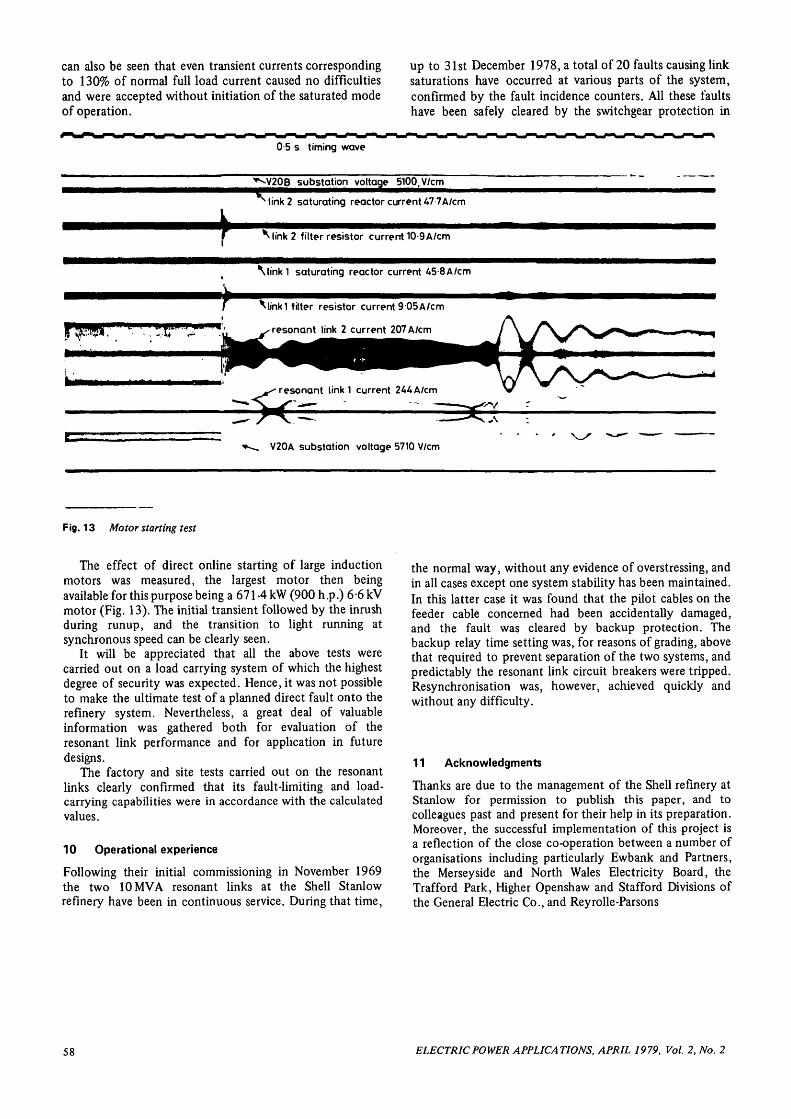
Fig. 13 Motor starting test
The effect of direct online starting of large inductionmotors was measured, the largest motor then beingavailable for this purpose being a 671A kW (900 h .p.) 6 -6 kVmotor (Fig. 13). The initial transient followed by the inrushduring runup, and the transition to light running atsynchronous speed can be clearly seen.
It will be appreciated that all the above tests werecarried out on a load carrying system of which the highestdegree of security was expected. Hence, it was not possibleto make the ultimate test of a planned direct fault onto therefinery system. Nevertheless, a great deal of valuableinformation was gathered both for evaluation of theresonant link performance and for application in futuredesigns.
The factory and site tests carried out on the resonantlinks clearly confirmed that its fault-limiting and load-carrying capabilities were in accordance with the calculatedvalues.
10 Operational experience
Following their initial commissioning in November 1969the two 10MVA resonant links at the Shell Stanlowrefinery have been in continuous service. During that time,
the normal way, without any evidence of overstressing, andin all cases except one system stability has been maintained.In this latter case it was found that the pilot cables on thefeeder cable concerned had been accidentally damaged,and the fault was cleared by backup protection. Thebackup relay time setting was, for reasons of grading, abovethat required to prevent separation of the two systems, andpredictably the resonant link circuit breakers were tripped.Resynchronisation was, however, achieved quickly andwithout any difficulty.
11 Acknowledgments
Thanks are due to the management of the Shell refinery atStanlow for permission to publish this paper, and tocolleagues past and present for their help in its preparation.Moreover, the successful implementation of this project isa reflection of the close co-operation between a number oforganisations including particularly Ewbank and Partners,the Mersey side and North Wales Electricity Board, theTrafford Park, Higher Openshaw and Stafford Divisions ofthe General Electric Co., and Reyrolle-Parsons
58 ELECTRIC POWER APPLICATIONS, APRIL 1979, Vol. 2, No. 2